an axisymmetric infinite cylinder with two cracks and a
TRANSCRIPT

Turkish J. Eng. Env. Sci.31 (2007) , 29 – 52.c© TUBITAK
An Axisymmetric Infinite Cylinder with Two Cracks and a RigidInclusion
Mete Onur KAMAN and Mehmet Rusen GECITMiddle East Technical University, Department of Engineering Sciences, Ankara-TURKEY
e-mail: [email protected]
Received 10.08.2006
Abstract
This work considers the analysis of a cracked infinite cylinder with a rigid inclusion. The material of thecylinder is assumed to be linearly elastic and isotropic. The ends of the infinite cylinders are subjected toaxial tension. Solution of this problem can be obtained by superposition of solutions for an infinite cylindersubjected to uniformly distributed tensile loads at infinity (I), and an infinite cylinder having a penny-shapedrigid inclusion at z =0 and 2 penny-shaped cracks at z = ± L (II). General expressions for the perturbationproblem (II) are obtained by solving Navier equations using Fourier and Hankel transforms. Formulation ofthe problem is reduced to a system of 3 singular integral equations. By using the Gauss-Lobatto integrationformula, these 3 singular integral equations are converted to a system of linear algebraic equations, whichare solved numerically.
Key words: Axisymmetric, Infinite cylinder, Penny-shaped crack, Rigid inclusion, Stress intensity factor.
Introduction
Cylinders, like shafts, pins, bolts, screws, pipes, etc.,are the most widely used machine elements withaxisymmetric geometries, and, due to singularities,they have particular importance in fracture mechan-ics. They may have discontinuities in the form ofholes, notches, cracks, or inclusions, which are veryimportant factors influencing stress distributions inloaded elements. Stresses around these discontinu-ities may reach very large values in small regions,a phenomenon known as stress concentration. Fur-thermore, stresses become infinite at the corners ofelements or the edges of cracks and inclusions. Insuch cases, stress concentration cannot be definedas a strength parameter, and it is necessary to con-sider the stress distributions from a fracture mechan-ics point of view. Fracture toughness, which is awidely accepted fracture parameter, can be easilycalculated in terms of stress intensity factors. Forcracked semi-infinite or infinite cylinder configura-tions subjected to external forces, it is possible to de-
rive closed-form expressions for stresses in the body,assuming isotropic linear elastic material behavior.For linear elastic materials, individual components ofstress, strain, and displacement are additive (super-position). In many instances of analytical solutions,the principle of superposition allows stress intensitysolutions for complex configurations to be built fromsimple cases for which the solutions are well estab-lished. In this context, the problem of a crackedinfinite cylinder with a rigid penny-shaped inclusionhas not been solved by the analytical method usedin this study.
Sneddon and Welch (1963) analyzed the distri-bution of the stress in a long circular cylinder ofelastic material when it is deformed by the appli-cation of pressure to the inner surfaces of a penny-shaped crack situated symmetrically at the cen-ter of the cylinder. The equations of the classicaltheory of elasticity have been reduced to a Fred-holm integral equation of the second kind. Ben-them and Minderhoud (1972) solved the problem of asolid cylinder compressed axially between rough rigid
29

KAMAN, GECIT
stamps. Gupta (1973) considered a semi-infinitecylinder problem with a fixed short end. An ex-act formulation of the problem in terms of a sin-gular integral equation has been provided. Usingtransform methods, the axisymmetric end-problemfor a semi-infinite elastic circular cylinder has beenreduced to a system of singular integral equations byAgarwal (1978). As an application, an axisymmet-ric solution for joined dissimilar elastic semi-infinitecylinders under uniform tension has been given. Er-dol and Erdogan (1978) studied an elastostatic ax-isymmetric problem for a long thick-walled cylindercontaining a ring-shaped internal crack, or an edgecrack, using the transform technique. Nied and Er-dogan (1983) analyzed a long hollow cylinder con-taining an axisymmetric circumferential crack sub-jected to general non-axisymmetric external loads.The problem has been formulated in terms of a sys-tem of singular integral equations, with the Fouriercoefficients of the derivative of the crack surface dis-placement as density functions for a cylinder underuniform tension, bending by end couples, or self-equilibrating residual stresses. Isida et al. (1985)made an analysis of an infinite solid containing 2parallel elliptical cracks located in staggered posi-tions. Xiao et al. (1996) investigated the stress in-tensity factors of 2 penny-shaped cracks with differ-ent sizes in a three-dimensional elastic solid underuniaxial tension. A closed-form analytical solutionfor the stress intensity factors on the boundaries ofthe cracks was obtained when the center distancebetween the 2 cracks is much larger than the cracks.Leung and Su (1998) extended the two-level finiteelement method (2LFEM) to the accurate analysisof axisymmetric cracks, where both the crack geom-etry and applied loads were symmetrical about theaxis of rotation. Chen (2000) evaluated stress inten-sity factors in a cylinder with a circumferential crackwith an indirect method, the computing compliancemethod. Lee (2001, 2002) made analyses of the stressdistribution in long circular cylinders of elastic ma-terial, one containing a penny-shaped crack and theother a circumferential edge crack, when each wassubjected to a uniform shearing stress. Meshii andWatanabe (2001) presented the development of apractical method, using prepared tabulated data, tocalculate the Mode I stress intensity factor for aninner surface circumferential crack in a finite lengthcylinder. The method was derived by applying theauthor’s weight function for the crack based on thethin shell theory. Selvadurai (2002) examined the
axial tensile loading of a rigid circular disc, whichwas bonded to the surface of a half-space weakenedby a penny-shaped crack. Tsang et al. (2003) inves-tigated the stress intensity factors of multiple penny-shaped cracks in an elastic solid cylinder under ax-ial tensile loading. The fractal-like finite elementmethod is employed to study the interaction of mul-tiple cracks. An Eigen function expansion methodwas presented to obtain three-dimensional asymp-totic stress fields in the vicinity of the front of apenny-shaped discontinuity, e.g., crack and anticrack(infinitely rigid lamella), subjected to far-field tor-sion (Mode III), extension/bending (Mode I), andsliding shear/twisting (Mode II) loading (Chaudhuri,2003).
This study considers the axisymmetric elasticityproblem for an infinite cylinder containing 2 concen-tric penny-shaped cracks at z = ± L and a penny-shaped rigid inclusion with virtually zero thicknessat z = 0. The ends of the infinite cylinder of radius Aat z = ±∞ are under the action of axial tensile loadsof uniform intensity p0. The material of the cylinderis assumed to be linearly elastic and isotropic. Thesurface of the cylinder is free of stresses. General ex-pressions are obtained by using Hankel and Fouriertransforms on Navier equations. First, the bound-ary conditions at the surface of the infinite cylinderare satisfied. By using the boundary conditions ofthe cracks and the rigid inclusion, formulation of theproblem is reduced to a system of 3 singular integralequations. By using the Gauss-Lobatto integrationformula (Krenk, 1978), these singular integral equa-tions are converted to a system of linear algebraicequations, which are solved numerically. Variationsin Mode I and Mode II stress intensity factors atthe edges of the cracks, and the inclusion, probablepropagation angle, and the energy release rate forthe cracks are presented in graphical form.
Formulation of the problem
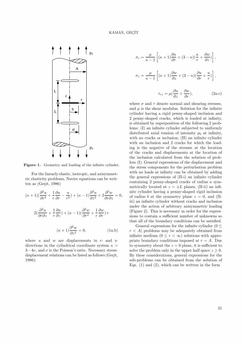
An axisymmetric, linearly elastic, isotropic, and in-finite cylinder of radius A, containing 2 concentricpenny-shaped cracks of radius a symmetrically lo-cated at z = ±L planes and a concentric penny-shaped rigid inclusion of radius b with negligiblethickness at the symmetry plane z = 0 is considered.Both ends of this infinite cylinder are subjected toaxial tensile loads of uniform intensity p0 at infinity(Figure 1).
30
KAMAN, GECIT
A
rz
b
a
p0
p0
L
L
Figure 1. Geometry and loading of the infinite cylinder.
For the linearly elastic, isotropic, and axisymmet-ric elasticity problems, Navier equations can be writ-ten as (Gecit, 1986)
(κ + 1)(∂2u
∂r2+
1r
∂u
∂r− u
r2) + (κ − 1)
∂2u
∂z2+ 2
∂2w
∂r∂z= 0,
2(∂2u
∂r∂z+
1r
∂u
∂z) + (κ − 1)(
∂2w
∂r2+
1r
∂w
∂r)+
(κ + 1)∂2w
∂z2= 0, (1a,b)
where u and w are displacements in r- and z-directions in the cylindrical coordinate system κ =3−4ν , and ν is the Poisson’s ratio. Necessary stress-displacement relations can be listed as follows (Gecit,1986):
σr =µ
κ − 1
[(κ + 1)
∂u
∂r+ (3− κ)(
u
r+
∂w
∂z)],
σz =µ
κ − 1
[(κ + 1)
∂w
∂z+ (3− κ)(
∂u
∂r+
u
r)],
τrz = µ(∂u
∂z+
∂w
∂r), (2a-c)
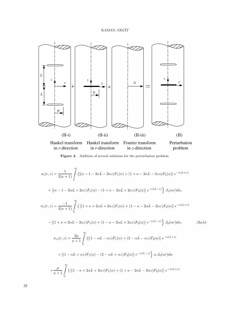
where σ and τ denote normal and shearing stresses,and µ is the shear modulus. Solution for the infinitecylinder having a rigid penny-shaped inclusion and2 penny-shaped cracks, which is loaded at infinity,is obtained by superposition of the following 2 prob-lems: (I) an infinite cylinder subjected to uniformlydistributed axial tension of intensity p0 at infinity,with no cracks or inclusion; (II) an infinite cylinderwith an inclusion and 2 cracks for which the load-ing is the negative of the stresses at the locationof the cracks and displacements at the location ofthe inclusion calculated from the solution of prob-lem (I). General expressions of the displacement andthe stress components for the perturbation problemwith no loads at infinity can be obtained by addingthe general expressions of (II-i) an infinite cylindercontaining 2 penny-shaped cracks of radius a sym-metrically located at z = ±L planes, (II-ii) an infi-nite cylinder having a penny-shaped rigid inclusionof radius b at the symmetry plane z = 0, and (II-iii) an infinite cylinder without cracks and inclusionunder the action of arbitrary axisymmetric loading(Figure 2). This is necessary in order for the expres-sions to contain a sufficient number of unknowns sothat all of the boundary conditions can be satisfied.
General expressions for the infinite cylinder (0 ≤r < A) problems may be adequately obtained frominfinite medium (0 ≤ r < ∞) solutions with appro-priate boundary conditions imposed at r = A. Dueto symmetry about the z = 0 plane, it is sufficient tosolve the problem only in the upper half space z ≥ 0.By these considerations, general expressions for thesub-problems can be obtained from the solution ofEqs. (1) and (2), which can be written in the form
31
KAMAN, GECIT
(II-i) (II-ii) (II-iii) (II)
Hankel transform Hankel transform Fourier transform Perturbation in r-direction in r-direction in z-direction problem
rz
a
L
L
rz
b
A rz
Figure 2. Addition of several solutions for the perturbation problem.
ui(r, z) =1
2(κ + 1)
∞∫0
{[(κ − 1− 2αL− 2αz)F1(α) + (1 + κ − 2αL− 2zα)F2(α)] e−α(L+z)
+ [(κ − 1− 2αL+ 2αz)F1(α)− (1 + κ − 2αL+ 2αz)F2(α)] e−α(L−z)}
J1(αr)dα,
wi(r, z) =−1
2(κ + 1)
∞∫0
{ [(1 + κ + 2αL+ 2αz)F1(α) + (1− κ − 2αL− 2αz)F2(α)] e−α(L+z)
− [(1 + κ + 2αL− 2αz)F1(α) + (1− κ − 2αL+ 2αz)F2(α)] e−α(L−z)}
J0(αr)dα, (3a,b)
σri(r, z) =2µ
κ + 1
∞∫0
{[(1− αL− αz)F1(α) + (2− αL− αz)F2(α)] e−α(L+z)
+ [(1− αL + αz)F1(α) − (2− αL+ αz)F2(α)] e−α(L−z)}
α J0(αr)dα
+µ
κ + 1
∞∫0
{ [(1− κ + 2αL+ 2αz)F1(α) + (1 + κ − 2αL− 2αz)F2(α)] e−α(L+z)
32

KAMAN, GECIT
+ [(1− κ + 2αL− 2αz)F1(α) + (1 + κ − 2αL+ 2αz)F2(α)] e−α(L−z)} J1(αr)
rdα,
σzi(r, z) =2µ
κ + 1
∞∫0
{[(1 + αL+ αz)F1(α)− α(L + z)F2(α)] e−α(L+z)
+ [(1 + αL− αz)F (α)− α(L− z)G(α)] e−α(L−z)}
α J0(αr)dα,
τrzi(r, z) =2µ
κ + 1
∞∫0
{ [α(L + z) F1(α) + (1 − αL− αz)F2(α)] e−α(L+z)
+ [−α(L+ z) F1(α)− (1− αL+ αz)F2(α)] e−α(L−z)}
α J1(αr)dα, (4a-c)
where J0 and J1 are the Bessel functions of the first kind of order zero and one, respectively,
F1(α) =
∞∫0
f1(r)rJ1(αr)dr, F2(α) =
∞∫0
f2(r)rJ0(αr)dr, (5a,b)
∂
∂r
[wi−2(r, L+)
]− ∂
∂r
[wi−1(r, L−)
]= f1(r), (0 ≤ r < ∞)
1r
∂
∂r
[rui−2(r, L+)
]− 1
r
∂
∂r
[rui−1(r, L−)
]= f2(r), (0 ≤ r < ∞) (6a,b)
such that fi(r) = 0 , (i = 1, 2) when (a < r < ∞), in (0 ≤ z ≤ L) for II-i,
uii(r, z) =1
2µ(κ + 1)
∞∫0
(−κ + αz)F3(α) e−α zJ1(αr)dα,
wii(r, z) =1
2µ(κ + 1)
∞∫0
αz F3(α) e−αzJ0(αr) dα , (7a,b)
σrii(r, z) =1
κ + 1
∞∫0
(κ − αz)F3(α) e−αz [J1(αr)/r] dα
− 12(κ + 1)
∞∫0
(3 + κ − 2αz)F3(α) e−α zα J0(αr)dα,
σz ii(r, z) =1
2(κ + 1)
∞∫0
(κ − 1− 2αz)F3 (α)e−α zα J0(αr)dα,
33

KAMAN, GECIT
τrz ii(r, z) =1
2(κ + 1)
∞∫0
(1 + κ − 2αz)F3(α)e−α zαJ1(αr)dα, (8a-c)
where
F3(α) =
∞∫0
f3(r)rJ1(αr)dr, (9)
τrz ii(r, 0+) − τrz ii(r, 0−) = f3(r), (0 ≤ r < ∞) (10)
f3(r) is the jump in the shearing stress τrz through the rigid inclusion and it is such that f3(r) = 0 when(b < r < ∞), in (0 ≤ z < ∞) for II-ii, and
uiii(r, z) =1π
∞∫0
[−c1I1(αr) + 2c2αrI0(αr)] cos(αz)dα,
wiii(r, z) =1π
∞∫0
{c1I0(αr)− 2c2 [(κ + 1)I0(αr) + αrI1(αr)]} sin(αz)dz , (11a,b)
σr iii(r, z) =2µπ
∞∫0
{c1 [I1(αr)/r − αI0(αr)] +c2
[(κ − 1)αI0(αr) + 2α2rI1(αr)
] }cos(αz)dα ,
σz iii(r, z) =2µπ
∞∫0
{c1αI0(αr) −c2
[(κ + 5)αI0(αr) + 2α2rI1(αr)
] }cos(αz)dα,
τrz iii(r, z) =2µπ
∞∫0
{c1αI1(αr) − c2
[(κ + 1)αI1(αr) + 2α2rI0(αr)
] }sin(αz)dα, (12a-c)
where I0 and I1 are the modified Bessel functions of the first kind of order zero and one, respectively, and c1
and c2 are arbitrary constants in (0 ≤ z < ∞) for II-iii.Now, the general expressions for the infinite medium containing 2 penny-shaped cracks and a penny-shaped
inclusion that is subjected to arbitrary axisymmetric loads (not at infinity) may be obtained when the individualexpressions are added:
uII = ui + uii + uiii,
wII = wi + wii + wiii, (13a,b)
σrII = σri + σrii + σriii,
σzII = σzi + σzii + σziii,
34

KAMAN, GECIT
τrzII = τrzi + τrzil + τrziii. (14a-c)
These expressions may give those for the perturbation problem for an infinite cylinder with a stress-free surfaceif they are forced to satisfy the homogeneous boundary conditions
σrII(A, z) = 0, (0 ≤ z < ∞)
τrzII (A, z) = 0, (0 ≤ z < ∞) (15a,b)
which give
c1 = Aα {[(κ − 1)I0(αA) + 2AαI1(αA)]αE1 + [(κ + 1)I1(αA) + 2AαI0(αA)]E2} /d0 ,
c2 = −{[AαI0(αA) − I1(αA)]αE1 +AαI1(αA)E2} /d0 , (16a,b)
in which one may show that
E1 = 4
a∫0
[d1 cos(αL)f1(t) + d2 sin(αL)f2(t)] tdt − (1/µ)
b∫0
d3f3(t)tdt ,
E2 = 4
a∫0
{d4 cos(αL)f1(t) +
[d5α + d6/A− (κ + 1)/2α2A2
]sin(αL)f2(t)
}tdt
−(1/µ)
b∫0
{d4 + (κ + 1) [K0(αA) + K1(αA)/αA] I1(αt)/2}f3(t)tdt , (17a,b)
d0 = (κ + 1) [2 A2α2I20 (Aα)− (1 + κ + 2A2α2)I2
1 (Aα )] ,
d1 = AK0(αA)I1(αt)− tK1(αA)I0(αt) ,
d2 = AK0(αA)I0(αt)− tK1(αA)I1(αt) ,
d3 = d1 + (κ + 1)K1(αA)I1(αt)/2α ,
d4 = αAK1(αA)I1(αt)− αtK0(αA)I0(αt) + d3/A ,
d5 = AK1(αA)I0(αt)− tK0(αA)I1(αt) ,
d6 = d2 + (κ + 1)K1(αA)I0(αt)/2α , (18a-g)
K0 and K1 are the modified Bessel functions of the second kind of order zero and one, respectively. Then,with the addition of the uniform solution (Artem and Gecit, 2002; Kaman, 2006; Toygar and Gecit, 2006),general expressions for the problem of an infinite cylinder with 2 cracks (0 ≤ r < a , z = ±L), an inclusion
35

KAMAN, GECIT
(0 ≤ r < b , z = 0), and a stress-free lateral surface (r = A) that is subjected to uniaxial tension of intensityp0 at z = ±∞ become
ucyl(r, z) =3− κ
κ − 7p0
2µr +
1κ + 1
a∫0
[d11(r, z, t)f1(t) + d12(r, z, t)f2(t)] tdt
+1
µ(κ + 1)
b∫0
d13(r, z, t)f3(t)tdt ,
wcyl(r, z) = − 4κ − 7
p0
2µz +
1κ + 1
a∫0
[d21(r, z, t)f1(t) + d22(r, z, t)f2(t)] tdt
+1
µ(κ + 1)
b∫0
d23(r, z, t)f3(t)tdt , (19a,b)
σrcyl(r, z) =µ
κ + 1
a∫0
[d31(r, z, t)f1(t) + d32(r, z, t)f2(t)] tdt
+1
κ + 1
b∫0
d33(r, z, t)f3(t)tdt ,
σzcyl(r, z) = p0 +µ
κ + 1
a∫0
[d41(r, z, t)f1(t) + d42(r, z, t)f2(t)] tdt
+1
κ + 1
b∫0
d43(r, z, t)f3(t)tdt,
τrzcyl(r, z) =µ
κ + 1
a∫0
[d51(r, z, t)f1(t) + d52(r, z, t)f2(t)] tdt +1
κ + 1
b∫0
d53(r, z, t)f3(t)tdt , (20a-c)
where dij(r, z, t), (i = 1−5, j = 1−3) have long expressions in the form of infinite integrals containing Besselfunctions, etc. and are given in Kaman (2006).
Integral equations
The expressions for the stresses and the displacements, Eqs. (19) and (20), contain 3 unknown functions,fi(t) , ( i =1 − 3). Since crack surfaces are free of stress and the rigid inclusion is assumed to be perfectly bonded to thecylinder, the stress and the displacement expressions must satisfy the following conditions
σz(r, L) = 0, (0 ≤ r < a)
36

KAMAN, GECIT
τrz(r, L) = 0, (0 ≤ r < a) (21a,b)
on the crack and
u(r, 0) = 0, (0 ≤ r < b) (21c)
on the rigid inclusion. Eqs. (21a) and (21b) are stress type boundary conditions, while Eq. (21c) is a displace-ment type, which is satisfied if
1r
∂
∂r[ru(r, 0)] = 0 (0 ≤ r < b) (21d)
is satisfied instead. Now, Eqs. (21a), (21b), and (21d) all are of the same (stress) type conditions.Substituting Eqs. (19) and (20) in Eqs. (21a), (21b), and (21d), and noting that f1(t) and f3(t) are odd,
and f2(t) is even, the following singular integral equations may be obtaineda∫
−a
{f1(t) [1/(t − r) +M2(r, t) + |t|N11(r, t) + |t|S1(r, t)] +f2(t) [N12(r, t) + S2(r, t)] |t|} dt
+(1/2µ)
b∫−b
f3(t) [N13(r, t) + S3(r, t)] |t|dt = −(κ + 1)π p0 /2µ, (−a < r < a)
a∫−a
{f1(t) [N21(r, t) + S4(r, t)] |t| + f2(t) [1(t − r) + M1(r, t) + |t|N22(r, t) + |t|S5(r, t)]} dt
+(1/8µ)
b∫−b
f3(t) [2N23(r, t) + S6(r, t)] |t|dt = 0, (−a < r < a)
a∫−a
{f1(t) [N31(r, t) + S7(r, t)] + f2(t) [N32(r, t) + S8(r, t)]} |t| dt
+(1/2µ)
b∫−b
f3(t) [−κ/(t − r)− κM2(r, t) + |t|N33(r, t)]dt
= (κ − 3)(κ + 1)π p0 /2µ(κ − 7), (−b < r < b) (22a-c)
where
Mi(r, t) = [mi(r, t) − 1] /(t − r) , (i = 1 , 2) , (23a,b)
m1(r, t) =
|t/r|E(|t/r|), |t| < |r|
E(|r/t|)t2/r2 − K(|r/t|)(t2 − r2)/r2, |t| > |r|,
m2(r, t) =
|r/t|E(|t/r|) + K(|t/r|)(t2 − r2)/ |tr| |t| < |r|
E(|r/t|), |t| > |r|(24a,b)
37

KAMAN, GECIT
in which Kand E are the complete elliptic integralsof the first and the second kinds, respectively. Thekernels Nij(r, t) (i, j = 1 − 3) are in the form ofimproper integrals,
Nij(r, t) =
∞∫0
Kij(r, t, α)dα, (i, j = 1− 3) (25)
where the integrands Kij(r, t, α), (i, j = 1 − 3) to-gether with Si(r, t), (i = 1− 8) containing completeelliptic integrals are given in the Appendix. The 3singular integral equations, Eqs. (22a), (22b), and(22c) must be solved in such a way that the single-valuedness conditions for the cracks and the equilib-rium equation for the rigid inclusion
a∫−a
fi(t)tdt = 0 , (i = 1, 2),
b∫−b
f3(t)tdt = 0
(26a-c)
are also satisfied. In Eqs. (22a), (22b), and (22c),the simple Cauchy kernel, 1/(t − r), becomes un-bounded when t = r. The unknown functions,fi(t) , ( i = 1 − 3), are expected to have integrablesingularities at the respective edges of cracks and theinclusion. The singular behavior of these unknownfunctions can be determined by writing
fi(t) = f∗i (t) (a
2 − t2)−β , (i = 1, 2) , (0 < Re(β) < 1)
f3(t) = f∗3 (t) (b
2 − t2)−γ , (0 < Re(γ) < 1)(27a-c)
where f∗i (t) , (i = 1−3) , are Holder-continuous func-
tions (Muskhelisvili, 1953) in the respective inter-vals (−a, a) and (−b, b). β and γ are unknown con-stants, which can be calculated by examining the
integral equations, Eqs. (22a) and (22b) near theends r = ∓a, and Eq. (22c) near the ends r = ∓b.By substituting Eq. (27) in Eqs. (22a), (22b), and(22c), calculating the integrals near r = ∓a andr = ∓b with the help of the complex function tech-nique given in Muskhelishvili (1953), following a pro-cedure similar to that given in Cook and Erdogan(1972), one can obtain the following characteristicequations:
cot(πβ) = 0, (0 ≤ Re(β) < 1) (a < A) (28a)
at the edge r = a , z = L of the penny-shapedcrack,
cot(πγ) = 0, (0 ≤ Re(γ) < 1) (b < A) (28b)
at the edge r = b , z = 0 of the penny-shaped in-clusion. The acceptable numerical value for β is 1/2from Eq. (28a). This is the very well known re-sult for an embedded crack tip in a homogeneousmedium (Cook and Erdogan, 1972; Erdol and Erdo-gan, 1978; Artem and Gecit, 2002; Toygar and Gecit,2006). Similarly, Eq. (28b) gives γ = 1/2, which isin agreement with previous results (Erdogan et al.,197n; Gupta, 1974; Nied and Erdogan, 1983; Artemand Gecit, 2002; Yetmez and Gecit, 2005; Toygarand Gecit, 2006).
Solution of integral equations
The integral equations will be expressed in termsof non-dimensional quantities. Defining non-dimensional variables φ and ψ on the crack by
r = aψ, t = aφ, (−a < (r, t) < a , −1 < (ψ, φ) < 1) (29a,b)
and η and ε on the inclusion by
r = bε, t = bη, (−b < (r, t) < b, −1 < (ε, η) < 1) (30a,b)
the system of singular integral equations, Eqs. (22) and (26), take the following form
1∫−1
{F1(φ) (1− φ2)−1/2
[1/(φ− ψ) +M2(ψ, φ) + |φ|N11(ψ, φ) + |φ|S1(ψ, φ)
]
+F2(φ) (1− φ2)−1/2[N
12(ψ, φ) + S2(ψ, φ)
]|φ|} dφ
38

KAMAN, GECIT
−1∫
−1
F3(η) (1− η2)−1/2[N13(ψ, η) + S3(ψ, η)
]( |η| /κ)dη = π(κ + 1)/ κ, (−1 < ψ < 1)
1∫−1
{F1(φ) (1− φ2)−1/2
[N21(ψ, φ) + S4(ψ, φ)
]|φ|
+ F2(φ) (1− φ2)−1/2[1/(φ − ψ) + M1 (ψ, φ) + |φ|N22(ψ, φ) + |φ|S5(ψ, φ )]
}dφ
−1∫
−1
F3(η) (1− η2)−1/2[N23(ψ, η) + S6(ψ, η)
](|η| /κ)dη = 0, (−1 < ψ < 1)
1∫−1
{F1(φ) (1 − φ2)−1/2
[N31(ε, φ) + S7(ε, φ)
]+ F2(φ) (1− φ2)−1/2
[N32(ε, φ) + S8(ε, φ)
]}|φ| dφ
+
1∫−1
F3(η) (1 − η2)−1/2[1/(η − ε) +M2(ε, η)− (|η| /κ)N33(ε, η)
]dη
= 2π(κ − 3) (κ + 1)/(7− κ)κ, (−1 < ε < 1) (31a-c)
1∫−1
Fi(φ) (1− φ2)−1/2φ dφ = 0 , (i = 1− 3), (32a-c)
where
Fi(φ) = −2µ (1− φ2)1/2fi(aφ)/κ p0 , (i = 1, 2), F3(η) = (1− η2)1/2f3(bη)/p0, (33a-c)
M i (i = 1, 2) , N ij (i, j = 1− 3), Si (i = 1− 8) are dimensionless kernels, as defined by Kaman (2006). Theintegrals in Eqs. (31) and (32) may be calculated by the use of the Gauss-Lobatto integration formula (Krenk,1978; Artem and Gecit, 2002). Then, Eqs. (31) and (32) may be put into the form
n/2∑i=1
Ci
{F 1(φi)
[m4(ψj , φi) + φiN11(ψj , φi) + φiS1(ψj, φi)
]
+F2(φi)[N12(ψj , φi) + S2(ψj , φi)
]φi −F3(ηi)
[N13(ψj , ηi) + S3(ψj, ηi)
](ηi/κ)
}
= (κ + 1)/κ, (j = 1, ..., n/2)
n/2∑i=1
Ci
{F1(φi)
[N21(ψj , φi) + S4(ψj , φi)
]φi
39

KAMAN, GECIT
+F2(φi)[m3(ψj , φi) + φiN22(ψj , φi) + φiS5(ψj, φi)
]
− F3(ηi)[N23(ξj , ηi) + S6(ξj , ηi)
](η2
i /κ)}= 0, (j = 1, ..., n/2)
n/2∑i=1
Ci
{F 1(φi)
[2N31(εj , φi) + 2S7(εj , φi)
]φi + F2(φi)
[2N32(εj , φi) + 2S8(εj , φi)
]φi
+F3(ηi)[m4(εj , ηi) − (2ηi/κ)N33(εj , ηi)
]}= 2(κ − 3) (κ + 1)/(7− κ)κ,
(j = 1, ..., n/2) (34a-c)
where
m3(ψj, φi) ={ [
2φi/(φ2i − ψ2
j )]E(φi/ψj) φi < ψj[
2φ2i /(φ
2i − ψ2
j )ψj
]E(ψj/φi)− (2/ψj) K(ψj/φi) φi > ψj
,
m4(εj , ηi) ={
(2/εj)K(ηi/εj) +[2εj/(η2
i − ε2j )
]E(ηi/εj) ηi < εj[
2ηi/(η2i − ε2
j )]
E(εj/ηi) ηi > εj, (35a,b)
φi, ηi = cos [(i − 1)π/(n − 1)] , (i = 1, ..., n)
ψj, εj = cos [(2j − 1)π/(2n − 2)] , (j = 1, ..., n− 1) (36a,b)
C1 = Cn = 1/(2n− 2), Ci = 1/(n− 1). (i = 2, ..., n− 1) (37)
Note here that Eqs. (32a) and (32c) are automati-cally satisfied since F 1(φ) and F3(η) are even func-tions. The system of equations, Eq. (34), contains3n/2 equations for 3n/2 unknowns, Fj(φi) , (i =1, ..., n/2; j = 1 − 3). However, if n is chosen tobe an even integer, it can be shown that Eq. (34b),corresponding to ψn/2 = 0, is satisfied automaticallysince
τrz(0, L) = 0. (38)
The missing equation, Eq. (34b), for j = n/2, iscomplemented by Eq. (32b), which can be convertedto
n/2∑i=1
CiφiF3(φi) = 0. (39)
It must be noted here that calculation of the coef-ficients for j = n/2, which corresponds to r = 0 in
Eqs. (34a) and (34c) requires special attention. In-finite integrals for kernels Nij(r, t), (i, j = 1− 3) arecalculated numerically by using the Laguerre inte-gration formula (Abramowitz and Stegun, 1965).
Numerical Results
The system of linear algebraic equations for theparticular problems defined in the previous sec-tion is solved and the values of unknown functionsFj(φi) , (i = 1, ..., n/2 ; j = 1− 3) can be calculatedat discrete collocation points. Then, stress distri-butions, stress intensity factors at the edges of thecrack, and the inclusion for an infinite cylinder canbe calculated numerically. From the viewpoint offracture, of particular importance are the stress in-tensity factors. Stresses become infinitely large atthe edges of the crack and the inclusion. In this case,
40

KAMAN, GECIT
stress states around those edges can be expressed interms of the power of stress singularity and stress in-tensity factors. The normal (Mode I) and the shear(Mode II) components of the stress intensity factors,k1a and k2a, at the edge of the crack may be definedas
k1a = limr→a
[2(r − a)] 1/2σz(r, L),
k2a = limr→a
[2(r − a)] 1/2τrz(r, L). (40a,b)
From Eqs. (20b) and (20c), one may write the ex-pressions for the stress components appearing in Eq.(40), separate the singular parts, calculate the inte-grals by the method given in Muskhelishvili (1953),substitute in Eq. (40), and obtain
k1a =κ
(κ + 1)p0
√a F 1(1) (42)
from which
k1a =k1a
p0√
a=
κ
(κ + 1)F 1(1) (43)
is obtained for the normalized Mode I stress intensityfactor at the edge of the penny-shaped crack. Onecan similarly write
k2a =κ
(κ + 1)F2(1) (44)
for the normalized Mode II stress intensity factor atthe edge of the penny-shaped crack.
Mode II stress intensity factor k2b at the edge ofthe rigid inclusion may be defined as
k2b = limr→b
[2(b − r)] 1/2τrz(r, 0), (45)
and can be calculated in the form
k2b =√
b
2p0F3 (1). (46)
Then, the normalized stress intensity factor becomes
k2b =k2b
p0
√b=
F3(1)2
. (47)
For the sake of generalizing the use of the numericalresults, dimensionless geometrical parameters a/A,b/A, and L/A normalized by the radius of the cylin-der are used. Since the normalized stress intensity
factors are calculated, particular numerical valuesare not selected for µ and p0, and ν is used to de-scribe the material. Some of the calculated resultsfor the following 5 cases are shown in Figures 3-15.
1. Two parallel penny-shaped cracks in an infi-nite solid:
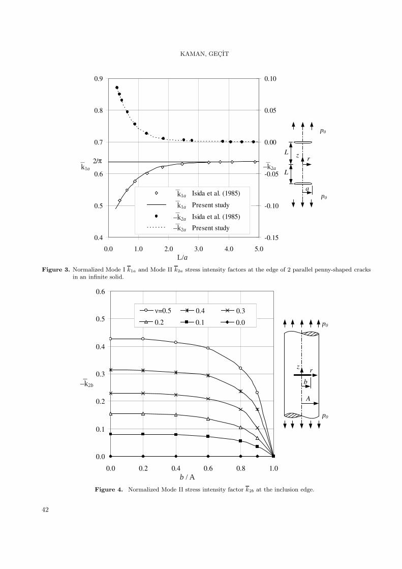
Figure 3 shows the normalized Mode I and ModeII stress intensity factors k1a and k2a at the edgesof 2 parallel penny-shaped cracks in an infinite soliddefined by Eqs. (42) and (43). These figures areproduced for the purpose of comparison with the re-sults given by Isida et al. (1985). k1a increases andk2a decreases with increasing L/a ratio, and remainsunchanged after L/a ∼= 4. As L/a goes to infinity,k1a goes to 2/π and k2a goes to zero, which are thevalues for a single penny-shaped crack. The resultsseem to be in very good agreement with those givenby Isida et al. (1985).
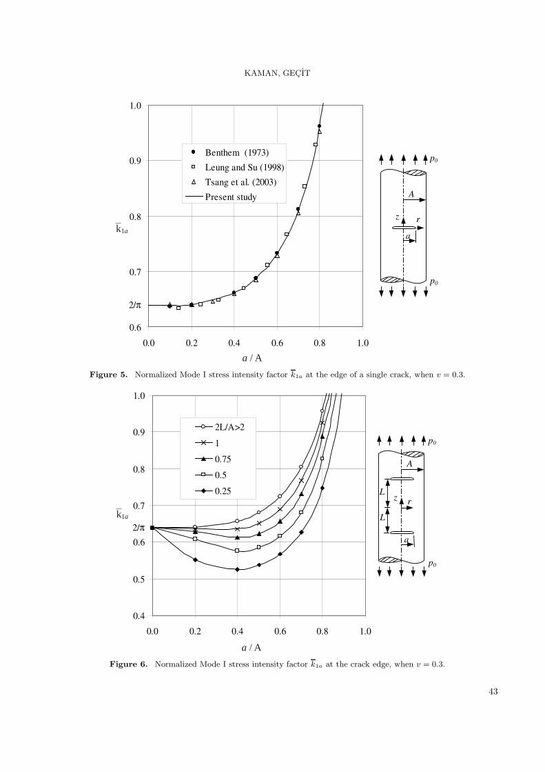
2. Infinite cylinder with a central rigid inclusion:Figure 4 shows the normalized Mode II stress in-
tensity factor k2b at the edge of the rigid inclusiondefined by Eq. (46). As can be seen from this figure,k2b is negative and it increases with increasing ν , butdecreases with increasing b/A ratio. Note that k2b iszero when ν = 0. For this situation, there is no Pois-son’s effect. Consequently, the constraint due to therigid inclusion disappears and the shearing stressesinduced by the inclusion vanish. For b/A= 1, theproblem reduces to that of a semi-infinite cylinderwith a fixed end at z = 0 (Gupta, 1974; Kamanand Gecit, 2006). In this special case, the power ofsingularity γ is < 0.5 and the stress intensity fac-tor calculated on the basis of γ = 0.5 must tend tozero as b/A→1. On the other hand, when b/A→0,the problem reduces to that of a finite rigid penny-shaped inclusion in an infinite medium.
3. Infinite cylinder with a single crack:Figure 5 shows the normalized Mode I stress in-
tensity factor k1a at the edge of a single transversepenny-shaped crack in an infinite cylinder, togetherwith the results given in Benthem and Koiter (1973),Leung and Su (1998), and Tsang et al. (2003) forcomparison. The results seem to agree with the pre-vious ones, the best agreement being with Benthemand Koiter (1973). The limiting value of k1a fora/A→0 is 2/π, which is the value for an infinitemedium, and it increases with increasing crack ra-dius.
41
KAMAN, GECIT
0.4
0.5
0.6
0.7
0.8
0.9
0.0 1.0 2.0 3.0 4.0 5.0
-0.15
-0.10
-0.05
0.00
0.05
0.10
Isida et al. (1985)
Present study
Isida et al. (1985)
Present study
2/π rz
a
p0
p0
L
L
L/a
–k2ak1a
k1a
k1a
–k2a
–k2a
Figure 3. Normalized Mode I k1a and Mode II k2a stress intensity factors at the edge of 2 parallel penny-shaped cracksin an infinite solid.
b / A
–k2b
0.0
0.1
0.2
0.3
0.4
0.5
0.6
0.0 0.2 0.4 0.6 0.8 1.0
�=0.5 0.4 0.3
0.2 0.1 0.0
A
rz
b
p0
p0
Figure 4. Normalized Mode II stress intensity factor k2b at the inclusion edge.
42
KAMAN, GECIT
0.6
0.7
0.8
0.9
1.0
0.0 0.2 0.4 0.6 0.8 1.0
Benthem (1973)
Leung and Su (1998)
Tsang et al. (2003)
Present study
2/π
A
rz
a
p0
p0
a / A
k1a
Figure 5. Normalized Mode I stress intensity factor k1a at the edge of a single crack, when v = 0.3.
a / A
k1a
0.4
0.5
0.6
0.7
0.8
0.9
1.0
0.0 0.2 0.4 0.6 0.8 1.0
2L/A>2
1
0.75
0.5
0.25
2/π
A
rz
a
p0
p0
L
L
Figure 6. Normalized Mode I stress intensity factor k1a at the crack edge, when v = 0.3.
43

KAMAN, GECIT
4. Infinite cylinder with 2 parallel cracks:Figure 6 shows k1a at the edges of 2 parallel
penny-shaped cracks in an infinite cylinder. k1a
is almost insensitive to ν . In most cases, k1a in-creases with increasing a/A and/or L/A ratios. AsL/A → ∞, the infinite cylinder problem with 2penny-shaped cracks becomes similar to that of aninfinite cylinder with a central crack at the z = 0plane. Note that k1a converges to 2/π as a/A→0for fixed values of L/A.
Figure 7 shows variation in k2a at the edges of2 parallel penny-shaped cracks in an infinite cylin-der for ν = 0.3. From this figure, one may concludethat k2a increases with increasing crack radius. k2a
decreases as the cracks move away from each other.Note also that k2a converges to zero as a/A→0 forfixed values of L/A.
In most fracture analyses, approaches based onenergy considerations are used with some variation(Gecit, 1988). A crack is claimed to propagate if therate of release of the stored energy per unit growthof the crack exceeds the rate of change of the surface
energy required by the new surfaces. The energy re-lease rate for the crack may be calculated in the form(Erdogan and Sih, 1963; Gecit, 1988),
∂U
∂a=
π2a
µ( k2
1a + k22a ) (48)
where U is the strain energy. Figure 8 shows thedimensionless energy release rate
w =µ
π2a2p20
∂U
∂a(49)
for one crack when ν = 0.3. Note that w is largerfor larger L/A ratios, i.e. when interaction betweenthe 2 cracks is less. w starts with the value 4/π2,which is the value for a single penny-shaped crack inan infinite medium:
k1a =2π
p0
√a , k2a = 0 ; w =
4π2
(50)
for a/A→0 and increases significantly with increas-ing a/A ratio.
a / A
k2a
-0.05
0.00
0.05
0.10
0.15
0.20
0.25
0.30
0.0 0.2 0.4 0.6 0.8 1.0
0.5
1
1.5
2L/A>2
A
rz
a
p0
p0
L
L
–
Figure 7. Normalized Mode II stress intensity factor k2a at the crack edge, when v = 0.3.
44

KAMAN, GECIT
a / A
w
0.2
0.3
0.4
0.5
0.6
0.7
0.8
0.9
1.0
0.0 0.2 0.4 0.6 0.8 1.0
L/A>2
0.75
0.5
0.25
0.125
4/π 2
A
rz
a
p0
p0
L
L
Figure 8. Normalized energy release rate w, when ν = 0.3.
If the material of the cylinder is brittle, crackpropagation may be expected to take place, as sug-gested by Erdogan and Sih (1963), in a direction per-pendicular to the maximum cleavage stress, which isdefined by
k2a [1− 3 cos(θ)] − k1a sin(θ) = 0,
3k2a sin(θ) − k1a cos(θ) < 0. (51a,b)
Figure 9 shows the variation in the probablecleavage angle θ at the edge of the penny- shapedcrack at the z = L plane, when v = 0.3. As canbe seen in this figure, the 2 cracks propagate awayfrom each other, a tendency that is more pronouncedwhen the cracks are closer to each other. As a/A→0,θ → 0 for all fixed values of L/A since very smallcracks may be thought of as if they are far from allsurrounding effects and proceed within their planes.
5. Infinite cylinder with a central rigid inclusionand 2 parallel cracks:
Variation in the normalized Mode I stress inten-sity factor k1a at the edges of penny-shaped crackswith a/A is shown in Figure 10, when b = 0.5A. It
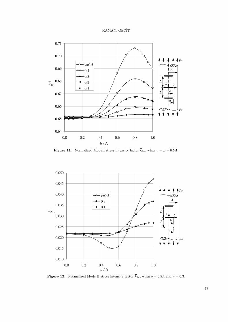
seems that k1a assumes its minimum value arounda = 0.5A. This effect is most pronounced for largervalues of ν and smaller values of L/A. Relativelyhigh stresses around the edge of the rigid inclusionare responsible for this behavior. It is obvious thatthe interaction between the rigid inclusion and thecracks is greater when the cracks are closer to theinclusion. The effect of the inclusion is greater forlarger ν . In addition to the interaction, k1a increasesas the crack radius increases. Figure 11 shows varia-tion in k1a with b/A, when a = 0.5A. Maximum val-ues of k1a are realized at b ∼= 0.8A for a = L = 0.5A.
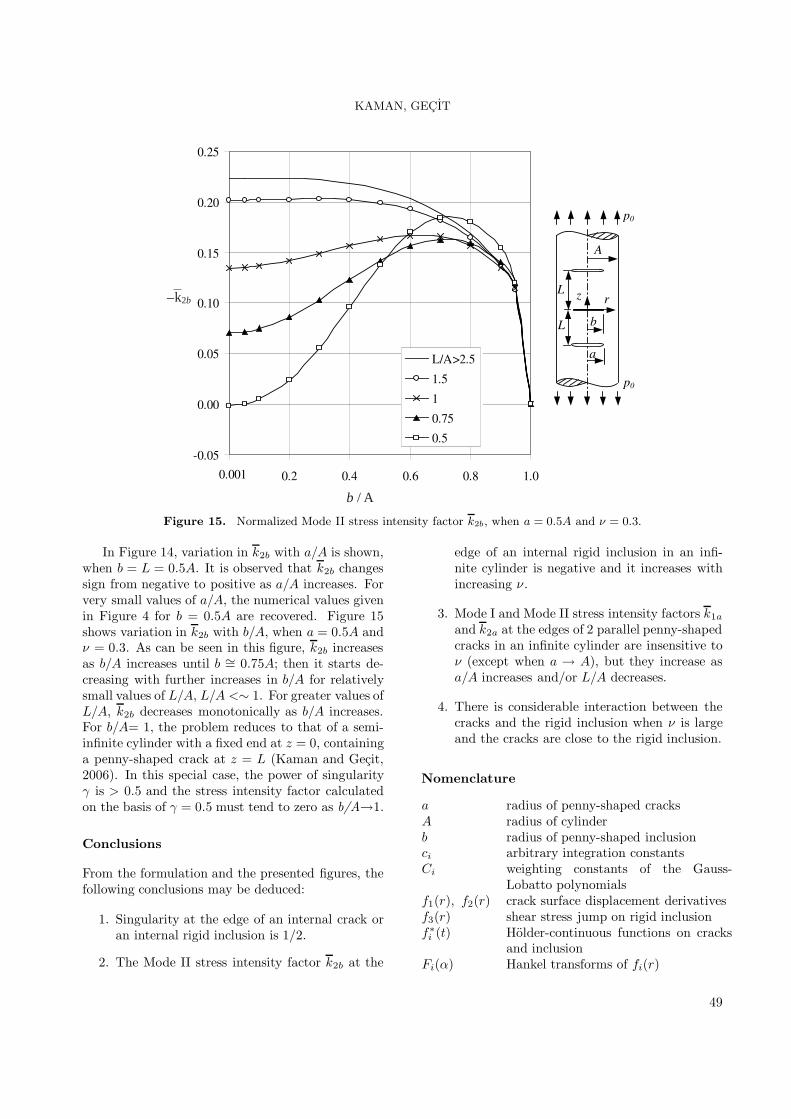
Figures 12 and 13 show variation in the normal-ized Mode II stress intensity factor k2a at the edgesof the cracks. In Figure 12, variation in k2a witha/A, when b = 0.5A is given. k2a converges tozero as a/A→0 for fixed values of L/A is negative,and its magnitude increases as the crack radius aand/or crack distance L increase(s) for b = 0.5Aand ν = 0.3. In Figure 13, variation in k2a withb/A is shown for a constant crack radius a = 0.5Aand L = 0.5A for several values of ν . As can beseen in Figure13, k2a is always negative. Relativelysmall variation for smaller values of ν and consider-able variation for larger values of ν are observed.
45

KAMAN, GECIT
a / A
0
5
10
15
20
25
0.0 0.2 0.4 0.6 0.8 1.0
L/A=0.125 0.25 0.5 0.75 1
A
rz
a
p0
p0
L
L
θ(°)
Figure 9. Probable crack propagation angle θ, when ν = 0.3.
0.60
0.65
0.70
0.75
0.80
0.85
0.90
0.0 0.2 0.4 0.6 0.8 1.0
�=0.5
0.4
0.3
0.2
0.1
0.001
A
rz
b
a
p0
p0
L
L
a / A
k1a
Figure 10. Normalized Mode I stress intensity factor k1a, when b = L = 0.5A.
46
KAMAN, GECIT
0.64
0.65
0.66
0.67
0.68
0.69
0.70
0.71
0.0 0.2 0.4 0.6 0.8 1.0
�=0.5
0.4
0.3
0.2
0.1
A
rz
b
a
p0
p0
L
L
b / A
k1a
Figure 11. Normalized Mode I stress intensity factor k1a, when a = L = 0.5A.
0.010
0.015
0.020
0.025
0.030
0.035
0.040
0.045
0.050
0.0 0.2 0.4 0.6 0.8 1.0
�=0.5
0.3
0.1
A
rz
b
a
p0
p0
L
L
a / A
k1a–
Figure 12. Normalized Mode II stress intensity factor k2a, when b = 0.5A and ν = 0.3.
47

KAMAN, GECIT
0.010
0.015
0.020
0.025
0.030
0.035
0.040
0.045
0.050
0.0 0.2 0.4 0.6 0.8 1.0
�=0.5
0.3
0.1
A
rz
b
a
p0
p0
L
L
b / A
k2a–
Figure 13. Normalized Mode II stress intensity factor k2a, when a = L = 0.5A.
-0.3
-0.2
-0.1
0.0
0.1
0.2
0.3
0.4
0.5
0.0 0.2 0.4 0.6 0.8 1.0
�=0.5
0.4
0.3
0.2
0.1 A
rz
b
a
p0
p0
L
L
a / A
k2b–
Figure 14. Normalized Mode II stress intensity factor k2b, when b = L = 0.5A.
48
KAMAN, GECIT
b / A
k2b–
-0.05
0.00
0.05
0.10
0.15
0.20
0.25
0.0 0.2 0.4 0.6 0.8 1.0
L/A>2.5
1.5
1
0.75
0.5
0.001
A
rz
b
a
p0
p0
L
L
Figure 15. Normalized Mode II stress intensity factor k2b, when a = 0.5A and ν = 0.3.
In Figure 14, variation in k2b with a/A is shown,when b = L = 0.5A. It is observed that k2b changessign from negative to positive as a/A increases. Forvery small values of a/A, the numerical values givenin Figure 4 for b = 0.5A are recovered. Figure 15shows variation in k2b with b/A, when a = 0.5A andν = 0.3. As can be seen in this figure, k2b increasesas b/A increases until b ∼= 0.75A; then it starts de-creasing with further increases in b/A for relativelysmall values of L/A, L/A <∼ 1. For greater values ofL/A, k2b decreases monotonically as b/A increases.For b/A= 1, the problem reduces to that of a semi-infinite cylinder with a fixed end at z = 0, containinga penny-shaped crack at z = L (Kaman and Gecit,2006). In this special case, the power of singularityγ is > 0.5 and the stress intensity factor calculatedon the basis of γ = 0.5 must tend to zero as b/A→1.
Conclusions
From the formulation and the presented figures, thefollowing conclusions may be deduced:
1. Singularity at the edge of an internal crack oran internal rigid inclusion is 1/2.
2. The Mode II stress intensity factor k2b at the
edge of an internal rigid inclusion in an infi-nite cylinder is negative and it increases withincreasing ν .
3. Mode I and Mode II stress intensity factors k1a
and k2a at the edges of 2 parallel penny-shapedcracks in an infinite cylinder are insensitive toν (except when a → A), but they increase asa/A increases and/or L/A decreases.
4. There is considerable interaction between thecracks and the rigid inclusion when ν is largeand the cracks are close to the rigid inclusion.
Nomenclature
a radius of penny-shaped cracksA radius of cylinderb radius of penny-shaped inclusionci arbitrary integration constantsCi weighting constants of the Gauss-
Lobatto polynomialsf1(r), f2(r) crack surface displacement derivativesf3(r) shear stress jump on rigid inclusionf∗
i (t) Holder-continuous functions on cracksand inclusion
Fi(α) Hankel transforms of fi(r)
49

KAMAN, GECIT
Fi normalized Holder-continuousfunctions on cracks and inclusion
Fi normalized bounded functionson cracks and inclusion
I0, I1; K0 , K1 modified Bessel functions of thefirst and second kinds of orderzero and one
J0, J1 Bessel functions of the first kindof order zero and one
k1a, k2a Mode I and II stress intensityfactors at the edge of crack
k1b, k2b Mode I and II stress intensityfactors at the edge of inclusion
k1a, k2a normalized Mode I and II stressintensity factors at the edge ofcrack
k1b, k2b normalized Mode I and II stressintensity factors at the edge of in-clusion
K, E complete elliptic integrals of thefirst and the second kinds
Kij integrands of the kernels Nij
L distance between cracks and in-clusion
m(r, t), m∗(r, t) kernels
mi, Mi, Ri, Si kernelsNij kernels of the integral equa-
tionsp0 intensity of the axial tensile
loadr, z radial and axial cylindrical
coordinatest integration variableu, w displacement components in
r- and z-directionsU strain energyw normalized energy release
rateα Fourier and Hankel transform
variableβ, γ powers of singularity at the
edge of cracks and inclusionη, ε ; φ, ψ normalized variables on inclu-
sion and cracksθ probable crack propagation
angleκ 3− 4νµ shear modulus of elasticityν Poisson’s ratioσ, τ normal and shearing stresses
References
Abramowitz, M. and Stegun, I.A., Handbook ofMathematical Functions, Dover Publications, NewYork, 1965.
Agarwal, Y.K., “Axisymmetric Solution of the EndProblem for a Semi-Infinite Elastic Circular Cylin-der and Its Application to Joined Dissimilar Cylin-ders under Uniform Tension”, International Journalof Engineering Science, 16, 985-998, 1978.
Artem, H.S.A. and Gecit, M.R., “An Elastic HollowCylinder under Axial Tension Containing a Crackand Two Rigid Inclusions of Ring Shape”, Comput-ers and Structures, 80, 2277-2287, 2002.
Benthem, J.P. and Minderhoud, P., “The Problemof the Solid Cylinder Compressed between RoughRigid Stamps”, International Journal of Solids andStructures, 8, 1027-1042, 1972.
Benthem, J.P. and Koiter, W.T., “Asymptotic Ap-proximations to Crack Problems”, Mechanics ofFracture 1, Methods of Analysis and Solutions ofCrack Problems, (ed. Sih, G.C.), Noordhoff Interna-tional Publishing, Leyden, The Netherlands, 1973.
Chaudhuri, R.A., “Three Dimensional AsymptoticStress Field in the Vicinity of the Circumference ofa Penny Shaped Discontinuity”, International Jour-nal of Solids and Structures, 40, 3787-3805, 2003.
Chen, Y.Z., “Stress Intensity Factors in a FiniteLength Cylinder with a Circumferential Crack”, In-ternational Journal of Pressure Vessels and Piping,77, 439-444, 2000.
Cook, T.S. and Erdogan, F., “Stresses in BondedMaterials with a Crack Perpendicular to the Inter-face”, International Journal of Engineering Science,10, 677-697, 1972.
Erdogan, F. and Sih, G.C., “On the Crack Exten-sion in Plates under Plane Loading and TransverseShear”, Journal of Basic Engineering-Transactionsof the ASME, 85, 519-527, 1963.
Erdol, R. and Erdogan, F., “Thick-Walled Cylin-der with an Axisymmetric Internal or Edge Crack”,Journal of Applied Mechanics-Transactions of theASME, 45, 281-286, 1978.
Gecit, M.R., “Axisymmetric Contact Problem fora Semi-Infinite Cylinder and a Half Space”, Inter-national Journal of Engineering Science, 24, 1245-1256, 1986.
Gecit, M.R., “Axisymmetric Pull-off Test for aCracked Adhesive Layer”, Journal of Adhesion Sci-ence and Technology, 2, 349-362, 1988.
50

KAMAN, GECIT
Gupta, G.D., “An Integral Approach to the Semi-Infinite Strip Problem”, Journal of Applied Mechan-ics, Transactions of the ASME, 40, 948-954, 1973.
Gupta, G.D., “The Analysis of Semi-Infinite Cylin-der Problem”, International Journal of Solids andStructures, 10, 137-148, 1974.
Isida, M., Hirota, K., Noguchi, H. and Yoshida,T., “Two Parallel Elliptical Cracks in an InfiniteSolid Subjected to Tension”, International Journalof Fracture, 27, 31-48, 1985.
Kaman, M.O., Cracked Semi-Infinite Cylinderand Finite Cylinder Problems, PhD Dissertation,Ankara, Turkey: Department of Engineering Sci-ences, Middle East Technical University, 2006.
Kaman, M.O. and Gecit, M.R., “Cracked Semi-Infinite Cylinder and Finite Cylinder Problems”,International Journal of Engineering Science, 44,1534-1555, 2006.
Krenk, S., “Quadrature Formulae of Closed Type forSolution of Singular Integral Equations”, Journal ofthe Institute of Mathematics and Its Applications,22, 99-107, 1978.
Lee, D.S., “Penny-Shaped Crack in a Long CircularCylinder Subjected to a Uniform Shearing Stress”,European Journal of Mechanics A-Solids, 20, 227-239, 2001.
Lee, D.S., “A Long Circular Cylinder with a Cir-cumferential Edge Crack Subjected to a UniformShearing Stress”, International Journal of Solids andStructures, 39, 2613-2628, 2002.
Leung, A.Y.T. and Su, R.K.L., “Two Level FiniteElement Study of Axisymmetric Cracks”, Interna-tional Journal of Fracture, 89, 193-203, 1998.
Meshii, T. and Watanabe, K., “Stress Intensity Fac-tor for a Circumferential Crack in a Finite-LengthThin to Thick-Walled Cylinder under an Arbitrary
Biquadratic Stress Distribution on the Crack Sur-face”, Engineering Fracture Mechanics, 68, 975-986,2001.
Muskhelishvili, N.I., Singular Integral Equations, P.Noordhoff, Groningen, Holland, 1953.
Nied, H.F. and Erdogan, F., “The Elasticity Prob-lem for a Thick-Walled Cylinder Containing a Cir-cumferential Crack”, International Journal of Frac-ture, 22, 277-301, 1983.
Selvadurai, A.P.S., “Mechanics of a Rigid Circu-lar Disk Bonded to a Cracked Elastic Half-Space”,International Journal of Solids and Structures, 39,6035-6053, 2002.
Sneddon, I.N. and Welch, J.T., “A Note on theDistribution of Stress in a Cylinder Containing aPenny-Shaped Crack”, International Journal of En-gineering Science, 1, 411-419, 1963.
Toygar, E.M. and Gecit, M.R., “Cracked InfiniteCylinder with Two Rigid Inclusions under Axisym-metric Tension”, International Journal of Solids andStructures, 43, 4777-4794, 2006.
Tsang, D.K.L., Oyadiji, S.O. and Leung, A.Y.T.,“Multiple Penny-Shaped Cracks Interaction in aFinite Body and Their Effect on Stress IntensityFactor”, Engineering Fracture Mechanics, 70, 2199-2214, 2003.
Xiao, Z.M., Lim, M.K. and Liew, K.M., “Determi-nation of Stress Field in an Elastic Solid Weakenedby Parallel Penny-Shaped Cracks”, Acta Mechanica,114, 83-94, 1996.
Yetmez, M. and Gecit, M.R., “Finite Strip with aCentral Crack under Tension”, International Jour-nal of Engineering Science, 43, 472-493, 2005.
Williams, M.L., “Stress Singularities Resulting fromVarious Boundary Conditions in Angular Corners ofPlates in Extension”, Journal of Applied Mechanics,19, 526-528, 1952.
Appendix
The expressions for the integrands Kij(r, t, α)(i, j = 1− 3) appearing in Eq. (25) are as follows
K11(r, t, α) =2αd0
[tαg7H00 + (2g5 − g1)H01 − 2trα2H10 + rαg5H11
]c2L , (A.1)
K12(r, t, α) =2
Ad0
[Aαg1(2g4 − 1)H00 + Atα2g7H01 + Arα2g5H10 − 2Atrα3H11
+(κ1 + 2g3)AαR0 −κ1A1(rαR1 + 2R0)] cLsL , (A.2)
51
KAMAN, GECIT
K13(r, t, α) = − α
2d0[2tαg7H00 + g9H01 −4trα2H10 + 2rαg6H11
]cL , (A.3)
K21(r, t, α) =2αd0
[−2trα2H00 + rαg5H01 + tαg5H10 − g1H11
]clsL , (A.4)
K22(r, t, α) =2αAd0
[Arαg5H00 − 2Atrα2H01 − Ag1H10 + Atαg5H11 + κ1(AA0R1 −rA1R0)] s2
L , (A.5)
K23(r, t, α) =α
2d0
[4trα2H00 − 2rαg6H01 − 2tαg5H10 + g8H11
]sL , (A.6)
K31(r, t, α) =1d0
[−2tα2g6H00 + αg8H01 + 2tαg2T0 − g2g5T1
]cL , (A.7)
K32(r, t, α) = − 1Aαd0
[−Aα2g1(2 + κ1 g4) H00 + 2Atα3(g1 + g3 + κ1g4)H01+
Aαg2g5T0 − 2Atα2g2T1 − κ1g2A1 + κ21αR0A1 +Aα2(2κ1 − g3)R0A0
]sL , (A.8)
K33(r, t, α) =12d0
{2tα2g6H00 − [g1 + 2κ1(κ + g3 + g5)]H01 − 2tαg2T0 + g2g6T1
}, (A.9)
where
κ1 = κ + 1 , κ2 = (κ − 1)2 , κ3 = κ − 3 , cL = cos(αL) , sL = sin(αL) , (A.10)
g1 = κ1 + 2A2α2, g2 = 4αR0 + 2rα2R1, g3 = 2A2α2A0K0, g4 = A1K1, g5 = g3 + g1g4 ,
g6 = g5 + κ1 , g7 = g5 − 4 , g8 = 2 g1 + κ1g5 , g9 = 2g1 − κ3g3 + κ2g1g4, (A.11)
Hij = RiTj , (j = 0, 1), Ri = Ii(rα) , Ti = Ii(tα) , Ai = Ii(Aα) , Ki = Ki(Aα) , (i = 0, 1) (A.12)
52