an efficient modal control strategy for the active vibration control of a truss...
TRANSCRIPT
Shock and Vibration 14 (2007) 393–406 393IOS Press
An efficient modal control strategy for theactive vibration control of a truss structure
Ricardo Carvalhala, Vicente Lopes Juniora,∗ and Michael J. BrennanbaMechanical Engineering Department, Universidade Estadual Paulista, UNESP/Ilha Solteira, 15385-000 IlhaSolteira, SP, BrazilbInstitute of Sound and Vibration Research, University of Southampton, Southampton, SO17 1BJ, UK
Received 29 September 2005
Revised 30 August 2006
Abstract. In this paper an efficient modal control strategy is described for the active vibration control of a truss structure. Inthis approach, a feedback force is applied to each mode to be controlled according to a weighting factor that is determined byassessing how much each mode is excited by the primary source. The strategy is effective provided that the primary source is ata fixed position on the structure, and that the source is stationary in the statistical sense. To test the effectiveness of the controlstrategy it is compared with an alternative, established approach namely, Independent Modal Space Control (IMSC). Numericalsimulations show that with the new strategy it is possible to significantly reduce the control effort required, with a minimalreduction in control performance.
Keywords: Intelligent truss structures, independent modal space control, piezoelectric stack actuator
1. Introduction
A truss structure is one of the most commonly used structures in aerospace and civil engineering [1]. Because it isdesirable to use the minimum amount of material for construction, the trusses are becoming lighter and more flexiblewhich means they are more susceptible to vibration. Passive damping is not a preferred vibration control solutionbecause it adds weight to the system, so it is of interest to study the active control of such a structure. A convenientway of controlling a truss structure is to incorporate a piezoelectric stack actuator into one of the truss members [2].A key issue is how many actuators to use [3], and where to place them [1]. Another issue is the dynamics of theactuators and whether these are important in terms of how they affect the vibration of the structure, and of coursethe control system [4,5]. Preumont et al. [6] used a local control strategy to suppress the low frequency vibrations ofa truss structure using two actuators. Their strategy involved the application of integrated force feedback using twoforce gauges each co-located with the two piezoelectric actuators, which were fitted into different beam elements inthe structure. In the work presented here, a single actuator is used and its position is determined using the methoddescribed by Carvalhal et al. [7]. The approach taken by Lammering et al. [5] is adopted to account for the actuatordynamics.
In many structures the lower modes of vibration have the most energy and are hence more critical. For this reason,these modes are often targeted for active control so that energy is not wasted in controlling the higher modes ofvibration [8]. A sensible control strategy, therefore, is to model the system in terms of modal parameters and tocontrol individual modes using modal space control strategies, such as IndependentModal Space Control (IMSC) [9].One of the problems with this approach, however, is that large control forces can be required as identified by Singh
∗Corresponding author. E-mail: [email protected].
ISSN 1070-9622/07/$17.00 2007 – IOS Press and the authors. All rights reserved
394 R. Carvalhal et al. / An efficient modal control strategy for the active vibration control of a truss structure
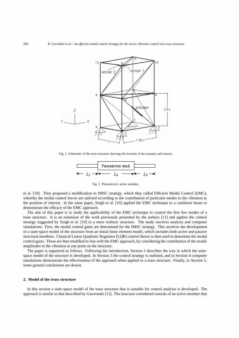
Fig. 1. Schematic of the truss structure showing the location of the actuator and sensors.
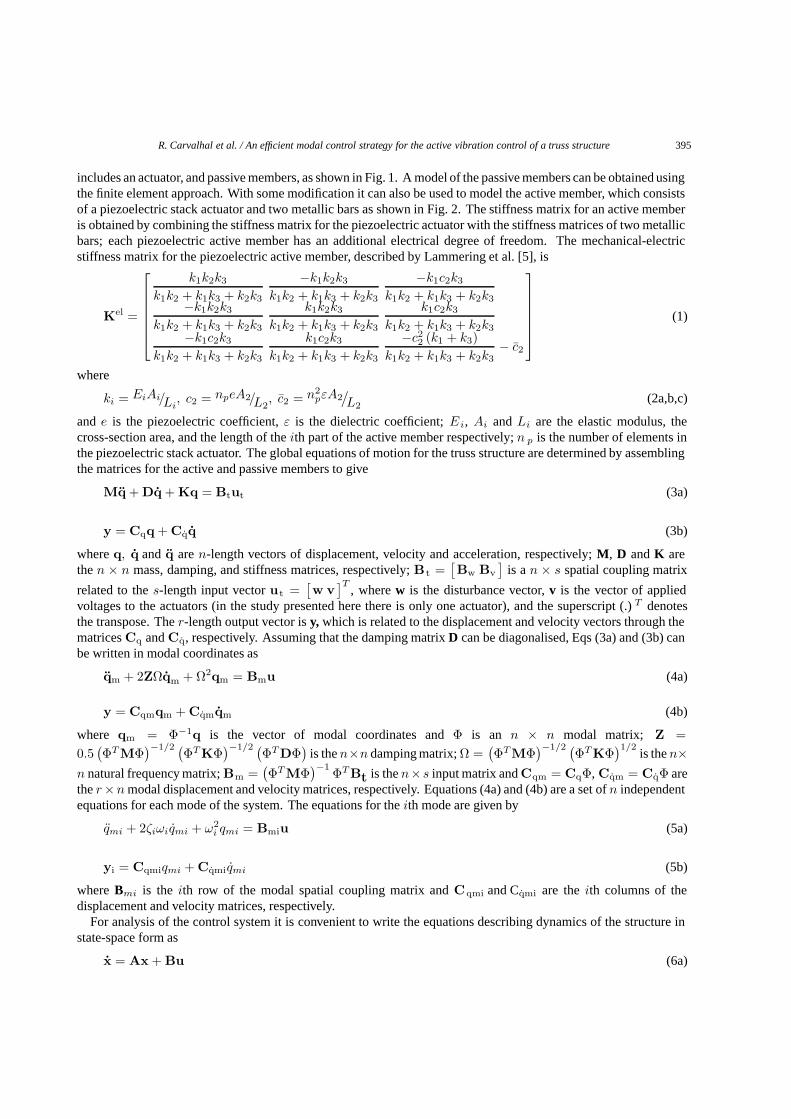
Fig. 2. Piezoelectric active member.
et al. [10]. They proposed a modification to IMSC strategy, which they called Efficient Modal Control (EMC),whereby the modal control forces are tailored according to the contribution of particular modes to the vibration atthe position of interest. In the same paper, Singh et al. [10] applied the EMC technique to a cantilever beam todemonstrate the efficacy of the EMC approach.
The aim of this paper is to study the applicability of the EMC technique to control the first few modes of atruss structure. It is an extension of the work previously presented by the authors [11] and applies the controlstrategy suggested by Singh et al. [10] to a more realistic structure. The study involves analysis and computersimulations. First, the modal control gains are determined for the IMSC strategy. This involves the developmentof a state-space model of the structure from an initial finite element model, which includes both active and passivestructural members. Classical Linear Quadratic Regulator (LQR) control theory is then used to determine the modalcontrol gains. These are then modified in-line with the EMC approach, by considering the contribution of the modalamplitudes to the vibration at one point on the structure.
The paper is organized as follows. Following the introduction, Section 2 describes the way in which the state-space model of the structure is developed. In Section 3 the control strategy is outlined, and in Section 4 computersimulations demonstrate the effectiveness of the approach when applied to a truss structure. Finally, in Section 5,some general conclusions are drawn.
2. Model of the truss structure
In this section a state-space model of the truss structure that is suitable for control analysis is developed. Theapproach is similar to that described by Gawronski [12]. The structure considered consists of an active member that
R. Carvalhal et al. / An efficient modal control strategy for the active vibration control of a truss structure 395
includes an actuator, and passive members, as shown in Fig. 1. A model of the passive members can be obtained usingthe finite element approach. With some modification it can also be used to model the active member, which consistsof a piezoelectric stack actuator and two metallic bars as shown in Fig. 2. The stiffness matrix for an active memberis obtained by combining the stiffness matrix for the piezoelectric actuator with the stiffness matrices of two metallicbars; each piezoelectric active member has an additional electrical degree of freedom. The mechanical-electricstiffness matrix for the piezoelectric active member, described by Lammering et al. [5], is
Kel =
k1k2k3
k1k2 + k1k3 + k2k3
−k1k2k3
k1k2 + k1k3 + k2k3
−k1c2k3
k1k2 + k1k3 + k2k3−k1k2k3
k1k2 + k1k3 + k2k3
k1k2k3
k1k2 + k1k3 + k2k3
k1c2k3
k1k2 + k1k3 + k2k3−k1c2k3
k1k2 + k1k3 + k2k3
k1c2k3
k1k2 + k1k3 + k2k3
−c22 (k1 + k3)
k1k2 + k1k3 + k2k3− c2
(1)
where
ki = EiAi/Li, c2 = npeA2/L2
, c2 = n2pεA2
/L2
(2a,b,c)
ande is the piezoelectric coefficient,ε is the dielectric coefficient;E i, Ai andLi are the elastic modulus, thecross-section area, and the length of theith part of the active member respectively;n p is the number of elements inthe piezoelectric stack actuator. The global equations of motion for the truss structure are determined by assemblingthe matrices for the active and passive members to give
Mq + Dq + Kq = Btut (3a)
y = Cqq + Cqq (3b)
whereq, q and q aren-length vectors of displacement, velocity and acceleration, respectively;M, D andK arethen × n mass, damping, and stiffness matrices, respectively;Bt =
[Bw Bv
]is an × s spatial coupling matrix
related to thes-length input vectorut =[w v
]T, wherew is the disturbance vector,v is the vector of applied
voltages to the actuators (in the study presented here there is only one actuator), and the superscript (.)T denotesthe transpose. Ther-length output vector isy, which is related to the displacement and velocity vectors through thematricesCq andCq, respectively. Assuming that the damping matrixD can be diagonalised, Eqs (3a) and (3b) canbe written in modal coordinates as
qm + 2ZΩqm + Ω2qm = Bmu (4a)
y = Cqmqm + Cqmqm (4b)
where qm = Φ−1q is the vector of modal coordinates andΦ is an n × n modal matrix; Z =0.5
(ΦTMΦ
)−1/2 (ΦTKΦ
)−1/2 (ΦTDΦ
)is then×n damping matrix;Ω =
(ΦTMΦ
)−1/2 (ΦTKΦ
)1/2is then×
n natural frequency matrix;Bm =(ΦTMΦ
)−1 ΦTBt is then×s input matrix andCqm = CqΦ, Cqm = CqΦ arether×n modal displacement and velocity matrices, respectively. Equations (4a) and (4b) are a set ofn independentequations for each mode of the system. The equations for theith mode are given by
qmi + 2ζiωiqmi + ω2i qmi = Bmiu (5a)
yi = Cqmiqmi + Cqmiqmi (5b)
whereBmi is the ith row of the modal spatial coupling matrix andCqmi and Cqmi are theith columns of thedisplacement and velocity matrices, respectively.
For analysis of the control system it is convenient to write the equations describing dynamics of the structure instate-space form as
x = Ax + Bu (6a)

396 R. Carvalhal et al. / An efficient modal control strategy for the active vibration control of a truss structure
Table 1Material properties and dimensions of the smart truss structure
Structure Active member
Elastic modulus (GPa) 210 52.6Mass density (kg/m3) 7800 7600Cross-section area (m2) 2.83× 10⁻⁵ 5.65× 10⁻⁵
L(m) 0.5 0.25Piezoelectric coefficient (N/V.m) — 44Dielectric coefficient (F/m) — 2.12× 10⁻⁸
Table 2Optimal feedback gains for the controlled modes
Mode number (i) Gdi(103) Gvi(103)
1 1.00 0.442 5.02 0.453 2.98 0.434 −1.05 −0.38
y = Cx (6b)
whereA is the 2n× 2n dynamic matrix,B is the 2n × s input matrix andC is ther× 2n output matrix. The statevectorx of modal displacements and velocities consists of 2n independent components,x i, that represent the state
of each mode and are given byx i =
qmi
qmi
, whereqmi is theith modal displacement andqmi is theith modal
velocity. The modal state-space realization is characterized by the block-diagonal dynamic matrix and the relatedinput and output matrices given by
A = blockdiag(Ami), B =
...Bmi
...
, C =
[ · · · Cmi · · ·]
(7)
where Ami =[0 1−ω2
i −2ζiωi
], andBmi andCmi are 2×s, andr× 2 blocks respectively,ζ i is the ith modal
damping ratio,ωi is theith natural frequency, and the subscript (.)mi relates to theith mode.The order of the state-space modal is large. However, a low order model is essential for the successful implemen-
tation of a controller. This can be obtained by partitioning the modes into those that will be controlled and those thatwill not be controlled. Thus, Eqs (6a) and (6b) can be written as.
xcxr
=
[Ac 00 Ar
] xcxr
+
[BcBr
]u (8a)
y =[Cc Cr
]xcxr
(8b)
where the subscripts (.)c and (.)r are for the controlled and residual modes, respectively.
3. Efficient modal control (EMC)
This control strategy is a simple modification of the IMSC, developed by Meirovitch and Baruh [9], and adescription of it is given in this section. As mentioned in the introduction, this method has been applied to a cantileverbeam [10], and here it is applied to a truss structure.
In IMSC the control force vector in physical space is given by (Jia [13])
ut = Lcu, whereLc =(LT L
)−1LT (9)

R. Carvalhal et al. / An efficient modal control strategy for the active vibration control of a truss structure 397
(a)
(b)
Fig. 3. Uncontrolled response for the reduced model with an impulsive force at (a) sensor 1 and (b) sensor 2.
whereL =(ΦT MΦ
)−1 ΦT Bt. An independent controller can be designed for each mode, hence the modalfeedback force in each modeu i is dependent onqmi andqmi alone, so that
ui = −Gdiqmi − Gviqmi (10)
whereGdi andGvi are the displacement and velocity modal gains, respectively. This ensures that the modal equations

398 R. Carvalhal et al. / An efficient modal control strategy for the active vibration control of a truss structure
(a)
(b)
Fig. 4. Spectra of the uncontrolled response for (a) sensor 1 and (b) sensor 2.
are not coupled through feedback. The modal control forcesu i are determined using optimal control theory [14],which determines feedback control gains by minimizing a quadratic performance indexJ i given by
Ji = 12
∞∫0
(xT
i Qixi + Riu2i
)dt = 1
2
∞∫0
(ω2
i q2mi + q2
mi + Riu2i
)dt (11)

R. Carvalhal et al. / An efficient modal control strategy for the active vibration control of a truss structure 399
(a)
(b)
Fig. 5. Uncontrolled and controlled response for the structure at (a) sensor 1 and (b) sensor 2, when the IMSC strategy is implemented.
where the diagonal matrixQi is the weighting matrix for theith modal state vector;R i is the weighting factor for the
ith modal control force, which trades control performance with control effort. WhenQ i =[ω2
i 00 1
], the performance
index is related to the sum of the potential energyω 2i q2
mi and the kinetic energyq2mi of the vibrating system as well
as the required input control effortu2i . Theith modal control force can be determined by
400 R. Carvalhal et al. / An efficient modal control strategy for the active vibration control of a truss structure
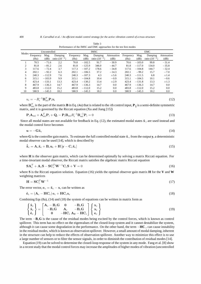
Table 3Performance of the IMSC and EMC approaches for the ten first modes
ModesUncontrolled IMSC EMC
Frequency Mag. Damping Frequency Mag. Damping Attenuation Frequency Mag. Damping Attenuation(Hz) (dB) ratio (10−4) (Hz) (dB) ratio (10−4) (dB) (Hz) (dB) ratio (10−4) (dB)
1 70.5 −71.6 2.2 70.8 −102.5 91.7 −30.9 70.6 −103.0 99.8 −31.42 81.8 −81.2 2.6 81.8 −125.9 346.0 −44.7 81.8 −117.0 134.0 −35.83 117.6 −72.4 3.7 117.3 −107.2 178.6 −34.8 117.6 −104.8 144.7 −32.44 202.1 −92.2 6.3 202.1 −106.5 37.2 −14.3 202.1 −99.2 15.7 −7.05 240.3 −112.9 7.6 240.3 −107.3 4.3 +5.6 240.3 −111.5 6.8 +1.46 315.1 −103.9 9.9 315.1 −104.8 10.4 −0.9 315.1 −104.5 10.1 −0.67 423.4 −133.1 13.3 423.4 −130.2 13.4 +2.9 423.4 −131.8 13.3 +1.38 467.9 −136.3 14.7 467.9 −136.3 14.7 0.0 467.9 −136.3 14.7 0.09 483.8 −112.0 15.2 483.8 −112.0 15.2 0.0 483.8 −112.0 15.2 0.0
10 580.9 −145.3 18.2 580.9 −145.3 18.2 0.0 580.9 −145.3 18.2 0.0
ui = −R−1i BT
miPixi (12)
whereBTmi is the part of the matrixB in Eq. (4a) that is related to theith control input,P i is a semi-definite symmetric
matrix, and it is governed by the Riccati equation (Xu and Jiang [15])
PiAmi + ATmiPi + Qi − PiBmiR
−1i B−1
mi Pi = 0 (13)
Since all modal states are not available for feedback in Eq. (12), the estimated modal statesx i are used instead andthe modal control force becomes
u = −Gxc (14)
whereG is the controller gain matrix. To estimate the full controlled modal statex c from the outputy, a deterministicmodal observer can be used [14], which is described by
ˆxc = Acxc + Bcuc + H [y − Ccxc] (15)
whereH is the observer gain matrix, which can be determined optimally by solving a matrix Riccati equation. Fora time-invariant modal observer, the Riccati matrix satisfies the algebraic matrix Riccati equation
SATc + AcS− SCT
c W−1CcS + V = 0 (16)
whereS is the Riccati equation solution. Equation (16) yields the optimal observer gain matrixH for theV andWweighting matrices
H = SCTc W−1 (17)
The error vector,ec = xc − x, can be written as
ec = (Ac − HCc) ec + HCrxr (18)
Combining Eqs (8a), (14) and (18) the system of equations can be written in matrix form as
xc
xr
ec
=
Ac − BcG 0 −BcG
−BrG Ar −BrG0 −HCr Ac − HCc
xc
xr
ec
(19)
The term−BrG is the cause of the residual modes being excited by the control forces, which is known as controlspillover. This term has no effect on the eigenvalues of the closed-loop system and it cannot destabilize the system,although it can cause some degradation in the performance. On the other hand, the term−HC r can cause instabilityin the residual modes, which is known as observation spillover. However, a small amount of modal damping, inherentin the structure can help to reduce the effects of observation spillover. Another way to minimize this effect is to usea large number of sensors or to filter the sensor signals, in order to diminish the contribution of residual modes [14].
Equation (19) can be solved to determine the closed-loop response of the system in any mode. Fang et al. [8] showin a recent study that the modal control forces may increase the amplitudes of higher modes of vibration (uncontrolled

R. Carvalhal et al. / An efficient modal control strategy for the active vibration control of a truss structure 401
(a)
(b)
Fig. 6. Spectra of the uncontrolled and controlled system at (a) sensor 1 and (b) sensor 2 when the IMSC strategy is implemented.
modes) if the IMSC algorithm is used to design a control system for a multi-degree-of-freedom structural system.Thus, the effects of control forces on higher modes must be considered in the response analysis.
The analysis above relates to IMSC. As mentioned previously, one of the problems with this control strategy is thatif a number of modes are excited, the voltages supplied to the control actuator(s) can be very large [10]. A significantreduction in the control force can be achieved with only a small reduction in performance, if the primary excitation
402 R. Carvalhal et al. / An efficient modal control strategy for the active vibration control of a truss structure
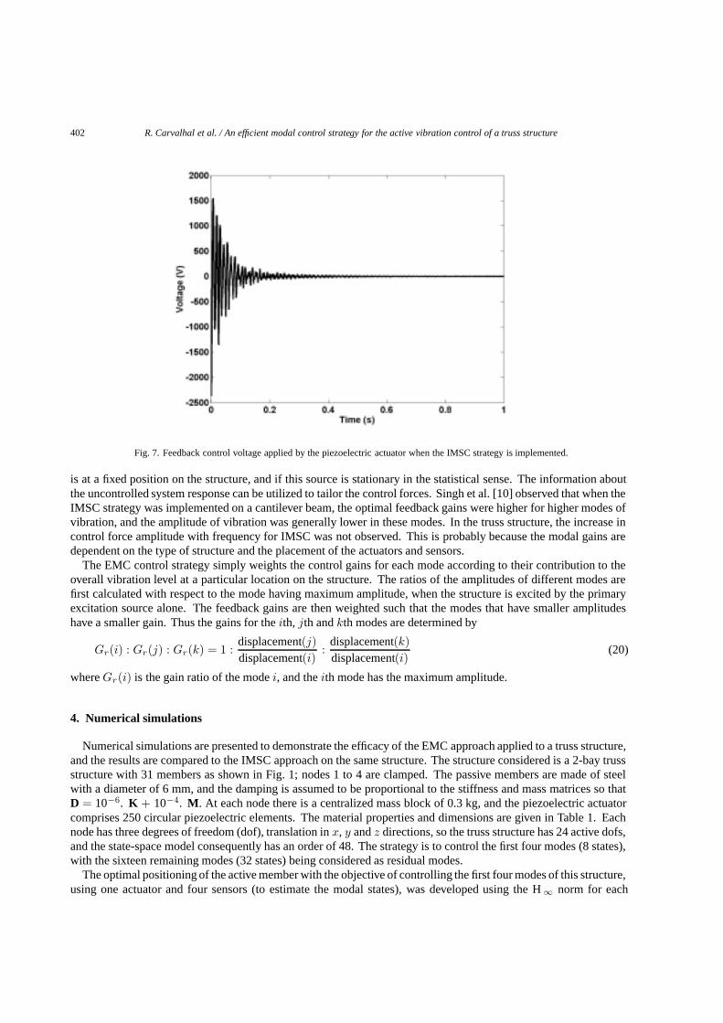
Fig. 7. Feedback control voltage applied by the piezoelectric actuator when the IMSC strategy is implemented.
is at a fixed position on the structure, and if this source is stationary in the statistical sense. The information aboutthe uncontrolled system response can be utilized to tailor the control forces. Singh et al. [10] observed that when theIMSC strategy was implemented on a cantilever beam, the optimal feedback gains were higher for higher modes ofvibration, and the amplitude of vibration was generally lower in these modes. In the truss structure, the increase incontrol force amplitude with frequency for IMSC was not observed. This is probably because the modal gains aredependent on the type of structure and the placement of the actuators and sensors.
The EMC control strategy simply weights the control gains for each mode according to their contribution to theoverall vibration level at a particular location on the structure. The ratios of the amplitudes of different modes arefirst calculated with respect to the mode having maximum amplitude, when the structure is excited by the primaryexcitation source alone. The feedback gains are then weighted such that the modes that have smaller amplitudeshave a smaller gain. Thus the gains for theith, jth andkth modes are determined by
Gr(i) : Gr(j) : Gr(k) = 1 :displacement(j)displacement(i)
:displacement(k)displacement(i)
(20)
whereGr(i) is the gain ratio of the modei, and theith mode has the maximum amplitude.
4. Numerical simulations
Numerical simulations are presented to demonstrate the efficacy of the EMC approach applied to a truss structure,and the results are compared to the IMSC approach on the same structure. The structure considered is a 2-bay trussstructure with 31 members as shown in Fig. 1; nodes 1 to 4 are clamped. The passive members are made of steelwith a diameter of 6 mm, and the damping is assumed to be proportional to the stiffness and mass matrices so thatD = 10−6. K + 10−4. M. At each node there is a centralized mass block of 0.3 kg, and the piezoelectric actuatorcomprises 250 circular piezoelectric elements. The material properties and dimensions are given in Table 1. Eachnode has three degrees of freedom (dof), translation inx, y andz directions, so the truss structure has 24 active dofs,and the state-space model consequently has an order of 48. The strategy is to control the first four modes (8 states),with the sixteen remaining modes (32 states) being considered as residual modes.
The optimal positioning of the active member with the objective of controlling the first four modes of this structure,using one actuator and four sensors (to estimate the modal states), was developed using the H∞ norm for each
R. Carvalhal et al. / An efficient modal control strategy for the active vibration control of a truss structure 403
(a)
(b)
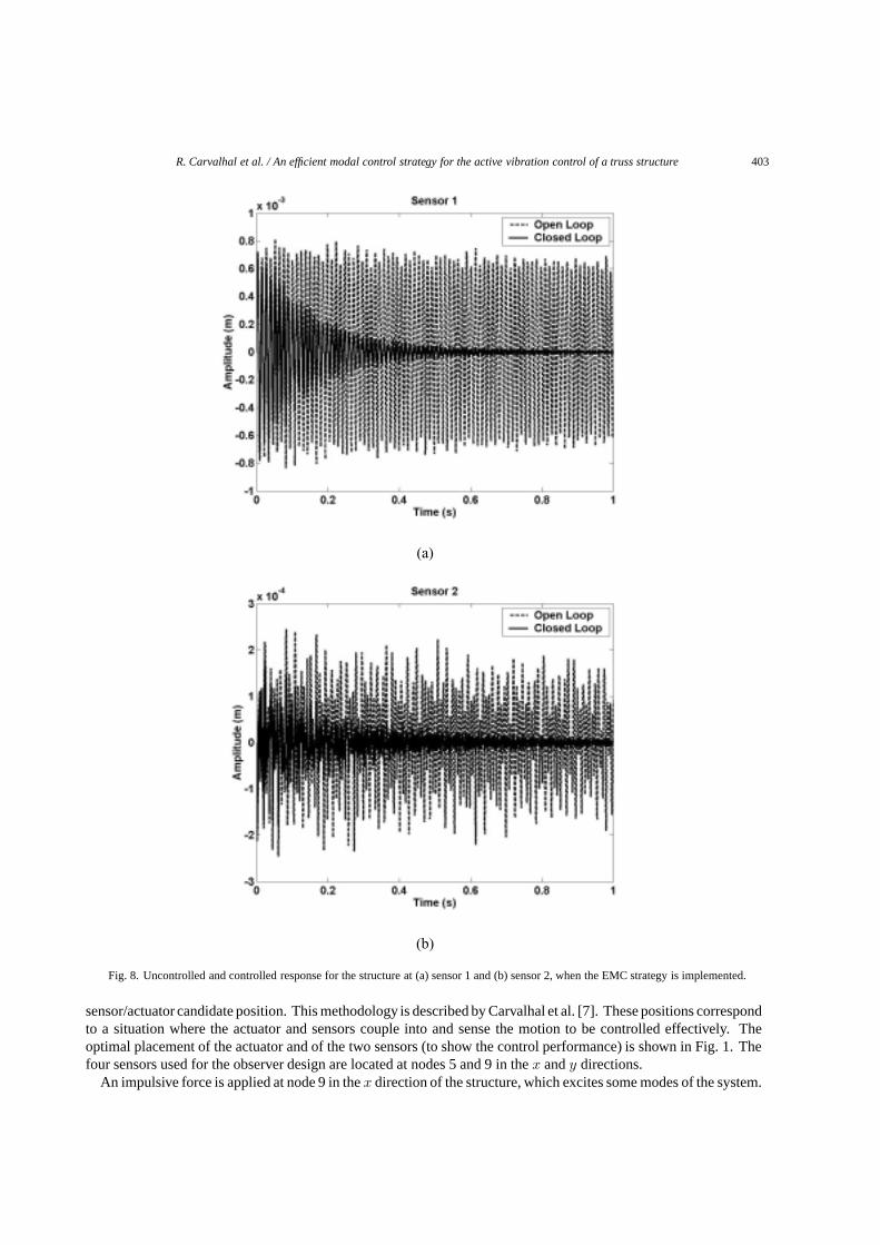
Fig. 8. Uncontrolled and controlled response for the structure at (a) sensor 1 and (b) sensor 2, when the EMC strategy is implemented.
sensor/actuator candidate position. This methodology is described by Carvalhal et al. [7]. These positions correspondto a situation where the actuator and sensors couple into and sense the motion to be controlled effectively. Theoptimal placement of the actuator and of the two sensors (to show the control performance) is shown in Fig. 1. Thefour sensors used for the observer design are located at nodes 5 and 9 in thex andy directions.
An impulsive force is applied at node 9 in thex direction of the structure, which excites some modes of the system.

404 R. Carvalhal et al. / An efficient modal control strategy for the active vibration control of a truss structure
(a)
(b)
Fig. 9. Spectra of the uncontrolled and controlled system at (a) sensor 1 and (b) sensor 2 when the EMC strategy is implemented.
This type of force is used as it will excite many modes of vibration and hence will be a difficult test for the controlsystem. The uncontrolled responses of the truss structure in the time domain at sensors 1 and 2 are shown in Fig. 3.The spectra of the uncontrolled responses are shown in Fig. 4. It should be noted that the response at sensor 1 ismuch larger than that at sensor 2. Using Eq. (12) withR = 10−5 IMSC feedback gains for the four controlled modesof the structure can be calculated and are given in Table 2. The actuator forces for different modes are summed to

R. Carvalhal et al. / An efficient modal control strategy for the active vibration control of a truss structure 405
Fig. 10. Feedback control voltage applied by the piezoelectric actuator when the EMC strategy is implemented.
give the resultant force required and hence the total voltage applied can be calculated. Figure 5 shows the controlledresponse of the truss structure measured by both sensors. With this configuration and weighting factor, the overallamplitude decreases from the initial value of about 0.8× 10⁻³ (m) to 0.5× 10⁻⁴ (m) in about 0.3 s measured bysensor 1 and from 2.5× 10⁻⁴ (m) to 0.4× 10⁻⁴ (m) in about 0.3 s measured by sensor 2. Figure 6 compares thespectra of uncontrolled and controlled responses at sensors 1 and 2. Figure 7 shows the feedback voltage suppliedto the actuator. The maximum control voltage required is 2350 V.
From the response spectra at sensor 2 shown in Fig. 4(b), the displacement amplitudes in the first four modes arefound to be [32.2, 9.1, 24.5, 2.8]× 10−5 m/N, respectively. Thus, optimal gains in these modes for the EMC controlstrategy were reduced by the ratios given in Eq. (20). Figure 8 shows the response of the structure when these gainsare applied. For EMC, the amplitude at sensor 1 decreases from the initial value of about 0.8× 10⁻³ (m) to 1.2×10⁻⁴ (m) in about 0.3 s and from 2.5× 10⁻⁴ (m) to 0.6× 10⁻⁴ (m) in about 0.3 s at sensor 2. Figure 9 comparesthe spectra of the uncontrolled and controlled system at sensors 1 and 2. The maximum control voltage supplied tothe actuator with the EMC approach is 900 V, and is shown in Fig. 10.
Table 3 lists the vibration attenuation in the first ten modes for the IMSC and EMC approaches, compared withthe uncontrolled system. It can be seen that in both approaches the control systems are effective. The amplitude ofthe first mode is attenuated by about 31 dB in each case. With the EMC strategy, the second, third and fourth modesare attenuated less than for the IMSC strategy as expected, but the performance is still very good. Furthermore, thecontroller does not influence the amplitude of mode 6, which is not explicitly included in the controller. Some peaksincrease, however, for example the amplitudes of modes 5 and 7 increase by 5.6 dB and 2.9 dB, respectively, forthe IMSC strategy, and by 1.4 dB and 1.3 dB respectively for the EMC strategy. This occurs, because of controlspillover.
A single quantity can be used as an overall judge of the control performance. It is the area under the curve ofthe absolute value of the displacement response. For the responses in Fig. 3 this is 17.5× 10⁻⁵ m.s and 3.75×10⁻⁵ m.s for sensor 1 and sensor 2, respectively. For the IMSC strategy (Fig. 5), these values are 3.10× 10⁻⁵ m.sfor sensor 1 and 1.28× 10⁻⁵ m.s for sensor 2, giving a reduction of 82.3% and 65.9%, respectively. For the EMCstrategy (Fig. 8), the values are 7.15× 10⁻⁵ m.s for sensor 1 and 1.91× 10⁻⁵ m.s for sensor 2, giving a reductionof 59.1% and 49.1%, respectively. Figures 5 and 8 shows that EMC and IMSC have comparable settling times,0.58 s for EMC and 0.44 s for IMSC. The difference lies in the vibration attenuation of the second, third and fourthmodal amplitudes, for which there is much reduced control effort with the EMC approach. Figures 7 and 10 clearly

406 R. Carvalhal et al. / An efficient modal control strategy for the active vibration control of a truss structure
show that the maximum feedback voltage supplied to the actuator for the EMC strategy is reduced by a factor of 2.6compared with the IMSC strategy. Also, the voltage amplitudes at the settling times are 35.7 V and 21.4 V for theIMSC and EMC strategy respectively, i.e., it is reduced by a factor of 1.6.
5. Conclusions
In this paper, an efficient modal control strategy has been applied to a truss structure, and its effectiveness has beencompared to that of the IMSC strategy. Optimal modal feedback gains are independent of the applied force for theIMSC algorithm, but by tailoring the gains according to the modal amplitudes at the location of interest, which aredependent on the applied force, significant reductions in the control force can be achieved, without a commensurateloss in performance. Simulations on a truss structure have demonstrated that, provided the nature of the primaryexcitation is known and is stationary, the simple modification of the IMSC strategy is very worthwhile.
Acknowledgements
The first two authors would like to acknowledge the financial support from Research Foundation of the State of SaoPaulo (FAPESP-Brazil). Prof. Brennan acknowledges the support from FAPESP (process number 04/133242-3 –Visiting Professor) and the Leverhulme Trust, UK.
References
[1] Y.J. Yan and L.H. Yam, A synthetic analysis on design of optimum control for an optimized intelligent structure,Journal of Sound andVibration 249 (2002), 775–784.
[2] D.K. Anthony and S.J. Elliott, On reducing vibration transmission in a two-dimensional cantilever truss structure using geometricoptimization and active vibration control techniques,Journal of the Acoustical Society of America 110 (2005), 1191–1194.
[3] W. Gao, J.J. Chen, H.B. Ma and X.S. Ma, Optimal placement of active bars in active vibration control for piezoelectric intelligent trussstructures with random parameters,Journal of Computers and Structures 81 (2003), 53–60.
[4] F. Liu and L. Zhang, Modal-Space control of flexible intelligent truss structures via modal filters,Proc. 18th International Modal AnalysisConference (IMAC) 1 (2000), 187–193.
[5] R. Lammering, J. Jia and C.A. Rogers, Optimal placement of piezoelectric actuators in adaptive truss structures,Journal of Sound andVibration 171 (1994), 67–85.
[6] A. Preumont, J.P. Dufour and C. Malekian, Active damping by a local force feedback with piezoelectric actuators,Journal of Guidance,Control and Dynamics 15 (1992), 390–395.
[7] R. Carvalhal, S. Silva and V. Lopes, Jr.,Robust Control Application for Smart Truss Structure, Proc. 23rd International Modal AnalysisConference (IMAC), in CD-ROM, ISBN 0912053895, 2005.
[8] J.Q. Fang, Q.S. Li and A.P. Jeary, Modified independent modal space control of m.d.o.f. system,Journal of Sound and Vibration 261(2003), 421–441.
[9] L. Meirovitch and H. Baruh, Optimal control of damped flexible gyroscopic systems,Journal of Guidance and Control 4 (1981), 157–163.[10] S.P. Singh, H.S. Pruthi and V.P. Agarwal, Efficient modal control strategies for active control of vibrations,Journal of Sound and Vibration
262 (2003), 563–575.[11] R. Carvalhal, V. Lopes, Jr. and M.J. Brennan,A Comparison of Two Modal Control Strategies for the Active Vibration Control of a Truss
Structure, (Vol. 1), Proc. 18th International Congress of Mechanical Engineering (COBEM), 2005, 304–310.[12] W. Gawronski,Dynamics and Control of Structures: A Modal Approach, Springer Verlag, New York, 1998.[13] J. Jia,Optimization of Piezoelectric Actuator Systems for Vibration Control of Flexible Structures, Ph.D. Dissertation, Virginia Polytechnic
Institute and State University, 1990.[14] L. Meirovitch, Dynamics and Control of Structures, John Wiley & Sons, New York, 1990.[15] B. Xu and J.S. Jiang, Integrated optimization of structure and control for piezoelectric intelligent trusses with uncertain placement of
actuators and sensors,Computational Mechanics 33 (2004), 406–412.

International Journal of
AerospaceEngineeringHindawi Publishing Corporationhttp://www.hindawi.com Volume 2010
RoboticsJournal of
Hindawi Publishing Corporationhttp://www.hindawi.com Volume 2014
Hindawi Publishing Corporationhttp://www.hindawi.com Volume 2014
Active and Passive Electronic Components
Control Scienceand Engineering
Journal of
Hindawi Publishing Corporationhttp://www.hindawi.com Volume 2014
International Journal of
RotatingMachinery
Hindawi Publishing Corporationhttp://www.hindawi.com Volume 2014
Hindawi Publishing Corporation http://www.hindawi.com
Journal ofEngineeringVolume 2014
Submit your manuscripts athttp://www.hindawi.com
VLSI Design
Hindawi Publishing Corporationhttp://www.hindawi.com Volume 2014
Hindawi Publishing Corporationhttp://www.hindawi.com Volume 2014
Shock and Vibration
Hindawi Publishing Corporationhttp://www.hindawi.com Volume 2014
Civil EngineeringAdvances in
Acoustics and VibrationAdvances in
Hindawi Publishing Corporationhttp://www.hindawi.com Volume 2014
Hindawi Publishing Corporationhttp://www.hindawi.com Volume 2014
Electrical and Computer Engineering
Journal of
Advances inOptoElectronics
Hindawi Publishing Corporation http://www.hindawi.com
Volume 2014
The Scientific World JournalHindawi Publishing Corporation http://www.hindawi.com Volume 2014
SensorsJournal of
Hindawi Publishing Corporationhttp://www.hindawi.com Volume 2014
Modelling & Simulation in EngineeringHindawi Publishing Corporation http://www.hindawi.com Volume 2014
Hindawi Publishing Corporationhttp://www.hindawi.com Volume 2014
Chemical EngineeringInternational Journal of Antennas and
Propagation
International Journal of
Hindawi Publishing Corporationhttp://www.hindawi.com Volume 2014
Hindawi Publishing Corporationhttp://www.hindawi.com Volume 2014
Navigation and Observation
International Journal of
Hindawi Publishing Corporationhttp://www.hindawi.com Volume 2014
DistributedSensor Networks
International Journal of