an efficient mac protocol for provisioning fairness in
TRANSCRIPT

AN EFFICIENT MAC PROTOCOL FOR
PROVISIONING FAIRNESS IN VEHICLE TO
ROADSIDE COMMUNICATIONS
By
Md. Abubakar Siddik
MASTER OF SCIENCE
IN
INFORMATION AND COMMUNICATION TECHNOLOGY
INSTITUTE OF INFORMATION AND COMMUNICATION TECHNOLOGY
BANGLADESH UNIVERSITY OF ENGINEERING AND TECHNOLOGY


Dedication
THIS THESIS IS DEDICATED
TO
MY PARENTS AND FRIENDS
iii

Contents
Declaration ii
Dedication iii
List of Tables vii
List of Figures ix
List of Abbreviations xii
List of symbols xiv
Acknowledgment xv
Abstract xvi
1 Introduction 1
1.1 Vehicle Ad Hoc Network (VANET) . . . . . . . . . . . . . . . . . . . 1
1.2 Applications of VANET . . . . . . . . . . . . . . . . . . . . . . . . . 2
1.3 Medium Access Control (MAC) Protocols for VANET . . . . . . . . 4
1.4 Motivation and Objectives . . . . . . . . . . . . . . . . . . . . . . . . 5
1.5 Related Work . . . . . . . . . . . . . . . . . . . . . . . . . . . . . . . 7
1.6 Organization of Thesis . . . . . . . . . . . . . . . . . . . . . . . . . . 9
1.7 Summary . . . . . . . . . . . . . . . . . . . . . . . . . . . . . . . . . 10
2 Overview of Vehicular Communications 11
2.1 Introduction . . . . . . . . . . . . . . . . . . . . . . . . . . . . . . . . 11
2.2 Standardization on Vehicular Communications . . . . . . . . . . . . . 11
2.3 Wireless Access in Vehicular Environment (WAVE): An Overview . . 14
2.3.1 WAVE protocol Stack . . . . . . . . . . . . . . . . . . . . . . 14
iv

2.3.2 IEEE 1609 Standards suite for WAVE . . . . . . . . . . . . . 15
2.3.3 IEEE 802 Standards for WAVE . . . . . . . . . . . . . . . . . 15
2.3.4 SAE Standards for WAVE . . . . . . . . . . . . . . . . . . . . 15
2.3.5 WAVE System Components and Connectivity . . . . . . . . . 16
2.3.6 WAVE Communication Modes . . . . . . . . . . . . . . . . . . 17
2.3.7 WAVE Channel Coordination and Time Synchronization . . . 19
2.3.8 Spectrum Allocation for WAVE . . . . . . . . . . . . . . . . . 20
2.3.9 Modulation Method of WAVE . . . . . . . . . . . . . . . . . . 21
2.4 Medium Access Control (MAC) Protocol . . . . . . . . . . . . . . . . 22
2.4.1 IEEE 802.11 DCF Scheme . . . . . . . . . . . . . . . . . . . . 22
2.4.1.1 Basic Access Mechanism of DCF Scheme . . . . . . 23
2.4.1.2 Hidden Terminal Problem . . . . . . . . . . . . . . . 23
2.4.1.3 RTS/CTS Access Mechanism of DCF Scheme . . . . 25
2.4.1.4 Exposed Terminal Problem . . . . . . . . . . . . . . 27
2.4.2 IEEE 802.11p EDCF Scheme . . . . . . . . . . . . . . . . . . 28
2.5 Fairness in Resource Allocation . . . . . . . . . . . . . . . . . . . . . 30
2.5.1 Different forms of fairness definition . . . . . . . . . . . . . . . 31
2.5.1.1 Targeted and Resultant Fairness . . . . . . . . . . . 31
2.5.1.2 Short-term and Long-term Fairness . . . . . . . . . . 31
2.5.1.3 System and Individual Fairness . . . . . . . . . . . . 32
2.5.2 Different Forms of Fairness Measurement . . . . . . . . . . . . 32
2.5.2.1 Quantitative/Absolute Fairness Measure and Quali-
tative/Relative Fairness Measure . . . . . . . . . . . 32
2.5.2.2 Utility Fairness Measure and Cost Fairness Measure 32
2.5.3 Fairness Measurement Schemes . . . . . . . . . . . . . . . . . 33
2.5.3.1 Jain’s Fairness Index . . . . . . . . . . . . . . . . . . 33
2.5.3.2 Entropy . . . . . . . . . . . . . . . . . . . . . . . . . 34
2.5.3.3 Max-min Fairness . . . . . . . . . . . . . . . . . . . . 34
2.5.3.4 Proportional Fairness . . . . . . . . . . . . . . . . . 35
2.6 Summary . . . . . . . . . . . . . . . . . . . . . . . . . . . . . . . . . 35
v

3 Proposed MAC Protocol for Provisioning Fairness in Vehicle to
Infrastructure Communications 36
3.1 Introduction . . . . . . . . . . . . . . . . . . . . . . . . . . . . . . . . 36
3.2 System Model . . . . . . . . . . . . . . . . . . . . . . . . . . . . . . . 37
3.3 Proposed MAC Protocol . . . . . . . . . . . . . . . . . . . . . . . . . 39
3.4 Modeling of the Proposed MAC Protocol . . . . . . . . . . . . . . . . 41
3.4.1 Batch Selection . . . . . . . . . . . . . . . . . . . . . . . . . . 41
3.4.2 Markov Chain Analysis . . . . . . . . . . . . . . . . . . . . . . 43
3.4.3 Throughput Analysis . . . . . . . . . . . . . . . . . . . . . . . 47
3.5 Summary . . . . . . . . . . . . . . . . . . . . . . . . . . . . . . . . . 48
4 Results and Performance Evaluation 49
4.1 Introduction . . . . . . . . . . . . . . . . . . . . . . . . . . . . . . . . 49
4.2 Analytical Results . . . . . . . . . . . . . . . . . . . . . . . . . . . . . 49
4.2.1 Selection of Minimum Contention Window Size . . . . . . . . 50
4.2.2 Comparison of Different Probabilities of Different Batches . . 51
4.2.2.1 Channel Idle Probability . . . . . . . . . . . . . . . . 51
4.2.2.2 Collision Probability . . . . . . . . . . . . . . . . . . 52
4.2.2.3 Successful Transmission Probability . . . . . . . . . . 53
4.2.2.4 Packet Drop Probability . . . . . . . . . . . . . . . . 54
4.2.2.5 Transmission Probability . . . . . . . . . . . . . . . . 55
4.2.3 Non-saturated Normalized Throughput Evaluation . . . . . . 56
4.2.3.1 Throughput of Different Batches . . . . . . . . . . . 56
4.2.3.2 Total Throughput of Vehicle . . . . . . . . . . . . . . 57
4.2.4 Maximum Transmitted Data of Different Protocols . . . . . . 58
4.2.5 Effect of Velocity on Packet Transmission . . . . . . . . . . . . 59
4.3 Summary . . . . . . . . . . . . . . . . . . . . . . . . . . . . . . . . . 59
5 Conclusion and Future Work 60
5.1 Conclusion . . . . . . . . . . . . . . . . . . . . . . . . . . . . . . . . . 60
5.2 Future Work . . . . . . . . . . . . . . . . . . . . . . . . . . . . . . . . 61
vi

List of Tables
1.1 Different types of VANET applications . . . . . . . . . . . . . . . . . 3
2.1 Example of Jain’s index . . . . . . . . . . . . . . . . . . . . . . . . . 33
2.2 Example of entropy . . . . . . . . . . . . . . . . . . . . . . . . . . . . 34
3.1 Batch selection and update . . . . . . . . . . . . . . . . . . . . . . . . 42
4.1 System parameters . . . . . . . . . . . . . . . . . . . . . . . . . . . . 49
4.2 Parameters used in numerical calculations . . . . . . . . . . . . . . . 50
4.3 Batch selection . . . . . . . . . . . . . . . . . . . . . . . . . . . . . . 57
vii

List of Figures
2.1 WAVE protocol stack containing both safety and non-safety applica-
tion part . . . . . . . . . . . . . . . . . . . . . . . . . . . . . . . . . 14
2.2 WAVE network architecture . . . . . . . . . . . . . . . . . . . . . . . 16
2.3 Unicast communication for both V2I and V2V network environment 17
2.4 Multicast/geocast communication for both V2I and V2V network en-
vironment . . . . . . . . . . . . . . . . . . . . . . . . . . . . . . . . . 18
2.5 Broadcast communication for both V2I and V2V network environ-
ment . . . . . . . . . . . . . . . . . . . . . . . . . . . . . . . . . . . 18
2.6 Channel interval of multichannel operation of WAVE . . . . . . . . . 19
2.7 Channel access options (a) continuous (b) alternating (c) immediate
and (d) extended . . . . . . . . . . . . . . . . . . . . . . . . . . . . . 20
2.8 Channel allocation of WAVE . . . . . . . . . . . . . . . . . . . . . . 21
2.9 OFDM sub-carriers assignment as defined by IEEE 802.11p standard 22
2.10 Flow chart of IEEE 802.11 DCF scheme for broadcast transmission . 24
2.11 Basic access mechanism of IEEE 802.11 DCF scheme . . . . . . . . . 25
2.12 Hidden terminal problem in V2V network environment . . . . . . . . 25
2.13 Hidden terminal problem in V2I network environment . . . . . . . . 26
2.14 RTS/CTS access mechanism of IEEE 802.11 DCF scheme . . . . . . 27
2.15 Exposed terminal problem for V2V network environment . . . . . . . 28
2.16 Architecture of IEEE 802.11p MAC channel coordination for multi-
channel operation . . . . . . . . . . . . . . . . . . . . . . . . . . . . 28
2.17 A simple illustration of a V2I environment of VANET . . . . . . . . 30
3.1 A V2I based VANET model . . . . . . . . . . . . . . . . . . . . . . . 37
3.2 Proposed architecture of IEEE 802.11 DCF MAC channel coordina-
tion for multi-channel operation . . . . . . . . . . . . . . . . . . . . . 38
3.3 Channel access mechanism of proposed MAC protocol . . . . . . . . . 39
viii

3.4 Markov chain model for the backoff procedure of a vehicle with both
saturated and non-saturated state . . . . . . . . . . . . . . . . . . . . 44
4.1 Selection of minimum contention window size based on transmission
probability . . . . . . . . . . . . . . . . . . . . . . . . . . . . . . . . 50
4.2 Probability of channel idle vs number of vehicle . . . . . . . . . . . . 51
4.3 Probability of collision vs number of vehicle . . . . . . . . . . . . . . 52
4.4 Probability of successful transmission vs number of vehicle . . . . . . 53
4.5 Probability of packet drop vs number of vehicle . . . . . . . . . . . . 54
4.6 Probability of transmission vs number of vehicle . . . . . . . . . . . 55
4.7 Throughput vs number of vehicle . . . . . . . . . . . . . . . . . . . . 56
4.8 Total throughput vs number of vehicle . . . . . . . . . . . . . . . . . 57
4.9 Number of transmitted packets vs residence time . . . . . . . . . . . 58
4.10 Maximum number of packet transmission vs different proposed pro-
tocols with considering different velocities . . . . . . . . . . . . . . . 59
ix

List of Abbreviations
2D Two Dimensional
2G 2nd Generation
3G 3rd Generation
3GPP 3rd Generation Partnership Project
AC Access Category
ACI Adjacent Channel Interference
ACK Acknowledgement
AIFS Arbitration Inter Frame Space
AIFSN Arbitration Inter Frame Space Number
ASTM American Society for Testing and Materials
C2C-CC Car2Car Communication Consortium
CALM Communications Access For Land Mobile
CCH Control Channel
CCHI Control Channel Interval
CEN European Committee for Standardization
CSMA/CA Carrier Sense Multiple Access with Collision Avoidance
CTS Clear to Send
CW Contention Window.
DCF Distributed Coordination Function
DIFS DCF Inter Frame Space
DSRC Dedicated Short Range Communications
EC European Commission
EDCA Enhanced Distributed Channel Access
EDCAF Enhanced Distributed Channel Access Function
EDGA Enhanced Data rates for GSM Evolution
ETSI European Telecommunications Standards Institute
FCC Federal Communication Commission
x

GI Guard Interval
GPRS General Packet Radio Service
GPS Global Positioning System.
IEEE Institute of Electrical and Electronics Engineering
IFS Inter Frame Space
IP Internet Protocol
IPv6 Internet Protocol version 6
ISO International Standards Organization
ITS Intelligent Transportation System.
LLC Logical Link Control
LTE Long Term Evolution
MAC Medium Access Control
MANET Mobile Ad Hoc Network
MSM Mixed Service Mobility
NAV Network Allocation Vector
OBU On Board Unit.
OFDM Orthogonal Frequency Division Multiplexing
OSI Open Systems Interconnection
PCF Point Coordination Function
PHY Physical
QoS Quality of Service
RFID Radio Frequency Identification
RSU Road Side Unit
RTS Request to Send
SAE Society for Automotive Engineers
SCH Service Channel
SCHI Service Channel Interval
SDO Standards Development Organization
SIFS Short Inter Frame Space
TC Technical Committee
TDMA Time Division Multiple Access
TXOP Transmission Opportunity
UTC Coordinated Universal Time
xi

V2D Vehicle to hand-held Device
V2I Vehicle to Infrastructure
V2V Vehicle to Vehicle
V2X Vehicle to Anything
VANET Vehicular Ad Hoc Network
WAVE Wireless Access in Vehicular Environment
WBSS WAVE Basic Service Set
WIBSS WAVE Independent Basic Service Set
WFQ Weighted Fair Queuing
WG Working Group
WiFi Wireless Fidelity
WiMAX Worldwide Interoperability of Microwave Access
WLAN Wireless Local Area Network
WSA WAVE Service Advertisement
WSM WAVE Short Message
WSMP WAVE Short Message Protocol
xii

List of symbols
Pi,j,k Probability of a vehicle of batch i is in backoff stage k with backoff
counter value k
Pcoll(i) Collision probability of batch i
Pidle(i) Channel idle probability when batch i has a packet to transmit
Psucc(i) Probability of successful transmission of batch i
Pdrop(i) Packet drop probability of batch i
Peqat(i) Probability that an vehicle of batch i has empty queue after
successful transmission or packet drop
Peq(i) Probability that an vehicle of batch i has empty queue
PB(i) Probability of a vehicle is in batch i
Wi,j Contention window size of batch i at backoff stage j
CWmin(i) Minimum contention window size of batch i
CWmax(i) Maximum contention window size of batch i
mi Maximum stage of batch i beyond which the contention window
will not be increased
mi + xi Retransmission limit of batch i
Pt(i) Transmission probability of batch i
ni Average number of vehicle of batch i
Tsucc Average time of a successful transmission
Tcoll Average time of a collision
σ Duration of a empty slot
Tp Average packet length in time
Ti Average residence time of batch i
Si Saturation throughput of batch i
Ri Packet transmission rate of batch i
H Normalized throughput of the network
Rbit Bit rate over the channel
xiii

Nbit Average number of bit in a packet
Np Average number of packet will be transmitted by the vehicle of batch 1
Tr Instantaneous residence time
R Radious of the coverage range of RSU
r Instantaneous distance of a vehicle from RSU
v Instantaneous velocity of a vehicle
vmax Maximum velocity in area of coverage range of RSU
vmin Minimum velocity in area of coverage range of RSU
Tr(min) Minimum residence time of vehicle
Tr(max) Maximum residence time of vehicle
xiv

Acknowledgment
All praises are for the almighty Allah for giving me the strength, without which I
could not afford to attempt this research work.
I would like to express my sincere and heartiest gratitude to my honorable thesis
supervisor Dr. Mohammad Shah Alam, Associate Professor, Institute of Informa-
tion and Communication Technology (IICT), Bangladesh University of Engineering
and Technology (BUET), Dhaka for his continuous motivation, guidance and keen
encouragement which helped me throughout the time of my research work. Nothing
is comparable to his keen advice and the freedom he provided for me in research. I
am grateful to him for his cooperation throughout my thesis work. I would like to
thank all honorable faculty members of IICT as well as other staffs. Additionally,
I would also like to thank my under graduate batch mates (CSE and TEE 2008
batch) of HSTU and lab mates (IICT, BUET) for their continuous support during
the long journey until my graduation.
I would like to thank all the members of the board of examiners for their precious
time in understanding my work and their insightful comments. I would like to thank
to all of my friends and colleagues for their cooperation. Last but not least, I am
grateful to my parents for their continuous supports and cooperation.
xv

Abstract
Vehicular ad hoc network (VANET) is an important component of intelligent trans-
ports system (ITS) that facilitates variety of safety and non-safety applications. It
has some unique characteristics, such as high geographically dynamic topology, pre-
dictable two direction mobility, varying vehicle density etc. Medium access control
(MAC) protocol plays a vital role to share the common wireless channel efficiently
among the vehicles in VANET. However, ensuring fairness is a challenging issue
to design MAC protocols of VANET. Due to small residence time, existing IEEE
802.11 DCF protocol provides less opportunity for the vehicles with high velocity
to communicate with road side unit (RSU), consequently allowing less amount of
data be transferred compared to the vehicles low velocity. Existing MAC protocols
take into account only velocities and can not ensure the data transmission rate to be
proportional to residence time while providing minimum amount of data transmis-
sion for all vehicles irrespective of velocity. Therefore, an efficient MAC protocol,
which takes position, direction and velocity of vehicles into consideration for ensur-
ing minimum opportunity for all the vehicles, is yet to be proposed. In this research
work, an efficient MAC protocol based on IEEE 802.11 DCF is developed which
minimizes the unfairness problem of VANET. Unfairness problem has two aspects:
higher velocity vehicles cannot transmit a minimum number of packets and lower
velocity vehicles cannot transmit above a maximum number of packets. To address
the above mentioned issues, the proposed MAC protocol adjusts the transmission
probability for each vehicle according to its residence time by changing the value
of MAC parameters (minimum contention window size, maximum backoff stage, re-
transmission limit, etc ) dynamically. An analytical model is developed to analyze
the performance of the proposed protocol. Analytical results show that the proposed
scheme overcomes the limitations of existing MAC protocols by ensuring that packet
transmission rate remains proportional to the residence time of the vehicles.
xvi

1
Chapter 1
Introduction
1.1 Vehicle Ad Hoc Network (VANET)
Vehicular ad hoc network (VANET) is a special type of mobile ad hoc network which
consists of moving vehicles, stationary road side units (RSU) and hand-held devices.
VANET is introduced as an important component of intelligent transport system
(ITS) to support variety of safety and non-safety applications. VANET use either a
single radio channel or multi-radio channel for communication in different networked
environment such as vehicle to vehicle (V2V), vehicle to infrastructure (V2I) and
vehicle to hand-held devices (V2D). VANET has some unique characteristics which
constitute VANET as a distinct research field in MANET [1–6].
• Geographically Highly Dynamic Topology: Due to high node mobility,
the network topology in a VANET changes very frequently.
• Predictable Network Topology: The movement of nodes in a VANET
is somewhat predictable because node movement is constrained by the road
topology.
• Predictable Two Direction Random Mobility: Nodes in a VANET can
move at very high speeds (160 km/h), which might lead to frequent discon-
nection among nodes.
• Unpredictable Radio Conditions: Due to high node mobility, distance
between transmitter and receiver varies with a short time so that transmitter
cannot predict the actual distance from receiver.
• Enough Battery Power: Unlike MANET nodes, nodes in VANET have no
energy limit.

2
• Significant Storage Capacity: VANET can provide sufficient storage due
to high configure WAVE devices.
• High Processing Power: VANET can provide enough power from the power
source of vehicles.
• Strict Delay Constrains: For safety application, it is guaranteed that the
end-to-end delay of course not cross the bounded time and a minimum delay
can tolerate by the non-safety application.
• Varying Node Density: The node density of a VANET may vary. The main
challenge in rural areas is network disconnection, while scalability is the main
challenge in high-density areas.
• Faster Joining and Leaving Rate: Due to high node mobility, joining and
leaving rate of the vehicles in a particular RSU or a cluster is very high.
• Infrastructure Support: Unlike most MANETs, VANETs can take advan-
tage of infrastructure on the roads. This could enhance the performance of
VANET MAC protocols.
• Availability of Location Information: Location information can be pro-
vided by having a global positioning system (GPS) receiver on board.
• Different QoS requirements: IEEE 802.11p MAC protocol provides quality
of service (QoS) for different types of safety and non-safety applications.
1.2 Applications of VANET
VANET is introduced for variety of safety and non-safety applications to provide
traffic safety, traffic efficiency and infotainment services to the commuting passen-
gers. The primary requirement of the safety applications is low latency and higher
throughput for non-safety applications. Different forms of safety and non-safety
applications are summarized in table 1.1.

3
Table 1.1: Different types of VANET applications
Safety
applications
Event-driven
safety
applications
Traveler
assistance
Post-crash notification
Predestrains crossing
Parking spot locate
Public
service
Stolen vehicles tracking
Traffic flow control
Approaching emergency vehicle warning
Driving
alert
Curve speed alart tracking
Lane change alert
Lane marging alert
Emergency break alert
Road
condition
alert
Vehicle-based alert
Infrastructure-based alert
Blind spot alert
Collision
alert
Wrong way driver alert
Intersection collision alert
Forward/rear collision alert
Traffic signal violation alert
Periodic safety
applications
Safety warning
Cooperative collision warning
Periodic vehicle-status reporting
Non-safety
applications
Passenger
infotainment
In-vehicle internet access
Mobile office
Media streaming
Driving assistance
Online navigation
Smart parking
Remote vehicle diagnostics
Traffic efficiency
and management
Toll payment services
Real-time traffic notification
Speed management

4
1.3 Medium Access Control (MAC) Protocols for VANET
Medium access control (MAC) Protocol is responsible to share common medium
among the participating nodes of the network. In VANET, a single radio channel is
used by different nodes of the networks. Different unique characteristics of VANET
impose several challenges to design MAC protocol [3].
• Unfairness: Due to relative motion between nodes, different priority of data,
worse link between nodes, collision of data, unfairness problem is occurred in
VANET.
• Reliability: One of the major challenges in the designing of the MAC protocol
for VANET is to achieve reliable delivery of message.
• Time-bounded Delivery : An important requirement for MAC protocol in
a vehicular environment is that it must be able to ensure delivery of safety
messages with an upper bound time delay.
• Efficiency: The MAC layer plays a crucial role in regulating the access to the
shared wireless medium so that multiple stations can share it efficiently.
• Robustness: The MAC protocol designed to elevate channel access mecha-
nism must be robust enough to handle hidden terminal and exposed terminal
problems.
• Distributive : It should pose minimal dependency on the RSU, that too with
an efficient handoff protocol from one RSU to another.
• Scalability: The MAC protocols should be designed to support under differ-
ent traffic load conditions.
• Packet Reception Probability : The MAC protocol should ensure that
messages are actually received (no lost packets) and delivered only once (no
duplicate packets), and are received in the proper order.
• Priority: Priority in managing access and communication time, the technique
should be able to give priority to some stations over other stations to facilitate
different type of services needed.

5
• Transmission Collision Recovery : If collision occurs, the protocol should
be able to recover from the collision.
• On Demand Channel Access : The MAC protocol should ensure that the
vehicle can access the channel on demand.
• Effective Delivery of Packet : The MAC protocol should ensure that
the vehicles can transmit or/and receive packet effectively with number of
retransmission as little as possible.
• Time synchronization: In order to be able to implement time-slotted MAC
protocols, clock synchronization between vehicles in VANETs is an important
issue.
• Multichannel operation: To ensure maximum connectivity and reduce col-
lision, vehicles use different channels simultaneously.
• Adjacent Channel Interference: Adjacent channel interference (ACI) is
occurred due to the parallel usage of the control channel (CCH) and the service
channels (SCHs).
1.4 Motivation and Objectives
Transportation and automobile industry has been long anticipating the deployment
of a complete autonomous vehicular network that will prevent accidents, facili-
tate eco-friendly driving, provide accurate real-time traffic information and offer
entertainment services to the commuting passengers. Vehicular ad hoc networks
(VANETs) is a special type of mobile ad hoc network which offers a promising pas-
sage to achieve this goal. In fact, the ability of vehicles to behave as mobile sensors
and to relay data qualifies them to be indispensable in the process of inaugurat-
ing an intelligent transportation system (ITS). VANET is introduced in the form of
vehicle to vehicle (V2V), vehicle to infrastructure (V2I) and vehicle to hand held de-
vice (V2D) communications, which are collectively referred to as vehicle to anything
(V2X) communications [7].
Different nodes of the VANET share a common medium for data transmission.
The medium access control (MAC) protocol is needed to share the common medium

6
among the nodes.The primary goal of an efficient MAC protocol in a VANET is to
maximize the throughput for non-safety application while minimizing the access
delay for safety applications. Due to the different velocity of the vehicles in the
coverage area of RSU, the residence time variation between vehicles is occurred.
Vehicles of less residence time do not get minimum chance to communicate with
RSU and consequently transmit less amount of data as compared to the vehicle of
high residence time. To support variety of safety and non-safety application, high
velocity vehicles will be needed a minimum chance to communicate with RSU to
fulfill at least safety application and other vehicles will be needed a certain chance
for communication with RSU which is proportional to their residence time. It is en-
sured by a relative fairness called proportional fairness. IEEE 802.11p standard [8]
defines MAC and PHY layer specifications for V2V communication of VANET. This
standard does not consider V2I communication. IEEE 802.11 standard [9] used for
V2I communication. This standard defines a MAC sublayer called distributed coor-
dination function (DCF). IEEE 802.11 DCF protocol is a random access mechanism
based on carrier sense multiple access with collision avoidance (CSMA/CA). IEEE
802.11 standard MAC protocol does not provide a minimum chance to high velocity
vehicles for communication with RSU because same MAC parameters (minimum
contention window, maximum backoff stage and retransmission limit) is used by all
vehicles. This protocol is not suitable for safety applications. The protocol provides
a certain chance to the vehicles which is proportional to their residence time and
is more applicable for non-safety application. A modified IEEE 802.11 DCF based
fair access MAC scheme is proposed in [10], which ensures the absolute fairness by
providing equal chance to all vehicles for communication with RSU. This protocol
consider that vehicle transmit only safety related message. Absolute fairness do not
ensure fair access channel for both safety and non-safety applications of VANET.
To resolve this problem an efficient IEEE 802.11 DCF based MAC protocol for ve-
hicle to infrastructure/roadside (V2I) communication of VANET is proposed in this
thesis work.
The goal of the research work is to overcome unfairness problem occurs due to veloc-
ity variation between different vehicles in vehicle to infrastructure (V2I) of VANET.
To meet the goal, the following objectives have been identified:

7
• To develop an efficient MAC protocol for VANET to ensure fairness.
• To develop an analytical model for the proposed protocol.
• To compare the results of proposed protocol with existing protocols.
1.5 Related Work
Performance analysis of the IEEE 802.11 DCF mechanism in either saturated or
non-saturated state has been recently studied in the literature [11–16]. In [11], P. E.
Engelstad et al. proposed a Markov chain model for the IEEE 802.11e EDCA mech-
anism to describe the normalized throughput, packet dropping probability and delay
when the network is in a non-saturated state. In [12], D. Malone et al. proposed
a Markov chain model for the IEEE 802.11 DCF mechanism to analyze the perfor-
mance of the network when the network is in a non-saturated state and nodes have
heterogeneous traffic. In [13], K. Duffy et al. proposed a Markov chain model for
the IEEE 802.11 DCF mechanism to analyze the performance of the network when
the network is in a non-saturated state and nodes have homogeneous traffic. In [14],
T. H. Luan et al. presented a Markov chain based analytical model for IEEE 802.11
DCF based MAC protocol for V2I communications in saturated sate and shows the
impacts of mobile nodes on the system throughput. In [15], T. O. Kim et al. present
Markov chain model for both IEEE 802.11 DCF and IEEE 802.11e EDCA scheme
to find the normalized channel throughput, average packet HoL (head of line) de-
lay, expected time to complete transmission of a flow and packet loss probability in
non-saturated condition. However, none of the above work considers the unfairness
problem for V2I communication in VANETs. Various TDMA based MAC proto-
cols have been discussed in [17–28] which assign one-time slot to each active vehicle
in different methods. Although several TDMA based MAC protocols [17–21] pro-
vide efficient packet delivery and fair channel access for fixed number of vehicles,
they cannot handle both sparse and dense mobility scenarios. Moreover, majority
of TDMA based MAC protocols [22–28] fail to achieve fairness for vehicles having
high variance in relative motion. Moreover, these approaches need strict synchro-
nization and can transmit only fixed length packets. In distributed TDMA based
MAC, access collision and merging collision problems can occur between vehicles.

8
In centralized TDMA based MAC, one-hop neighboring collision and hidden node
collision can arise between vehicles [29].
Proposal of MAC protocols based on IEEE 802.11 DCF to ensure fairness for V2I
communications in VANET has been studied in [10, 30–34]. In [30], W. Alasmary
et al. proposed two dynamic CW based mechanisms to alleviate the performance
degradation caused by different velocity of vehicles. However, they do not describe
the exact procedure for the selection of optimal contention window size to avoid
unfairness problem. In [10], to address unfairness problem, E. Karamad et al. pro-
posed a modified IEEE 802.11 DCF based MAC protocol which dynamically assigns
minimum contention window to each vehicle batch at the beginning of accessing the
network for the whole residence time by adjusting transmission probability with its
speed. They ensure absolute fairness considering the network is in a saturated state.
Moreover, they derived some relations between average velocity and the minimum
contention window of each batch through analytical approximations. Performance
analysis of this model, which is based on Bianchi model [35] has the following as-
sumptions:
1. Every node of the network always has at least one packet to transmit.
2. There are no hidden terminals and exposed terminals in the network and no
capture effect.
3. Each packet collides with constant and independent probability regardless of
current state of the node.
4. Transmission channel is ideal and transmission errors occur due to packet
collision only.
In [31], Q. Wu et al. presented a MAC protocol proposed by E. Karamad et al.
[10] and analyzed the performance by considering the network is in a non-saturated
state. Moreover, they derived the relationship between the transmission probability
and the minimum contention window size of a vehicle and the relationship between
the average velocity and the minimum contention window size of a vehicle in a
non-saturated state. Both authors [10, 31] consider a network model with following
assumptions:

9
1. The vehicles arrive in the network in batches according to Poisson process with
constant rate.
2. The vehicles in each batch have same average velocity and velocity remains
constant for whole residence time of a particular RSU.
3. Moving direction of each vehicle does not change and batch no of a vehicle
remains same for whole residence time.
Both authors [10,31] ensure the absolute fairness of the network which is appropriate
for safety applications only. They do not ensure the proportional fairness of the
network which is needed for both safety and non-safety applications.
In [32], V. P. Harigovindan et al. derived the analytical expression for optimum
CW required to ensure fairness, in the sense of equal opportunity to communicate
with RSU among the vehicles of different average velocity in the network. However,
they do not analyze the network performance of the network in both saturated
and non-saturated state. Although, this protocol can achieve the absolute fairness
but do not consider the proportional fairness which is required for both safety and
non-safety applications.
To address unfairness problem of V2I communications, Hoeft et al. [33] proposed
a RSU selection algorithm to obtain even attachment of OBUs to RSUs and to
minimize the variation of OBUs connected to each RSU. However, they do not
solve the unfairness problem among vehicles with different velocities for a particular
RSU. In [34], Zhang et al. build a Mixed-Service-Mobility (MSM) model for IEEE
802.11p scheme to analyze the interaction between delay-tolerant services and real-
time services under high speed mobility condition instead of four different access
categories (AC) defined by IEEE 802.11p standard. Although they ensure longtime
fairness for delay-tolerant services but do not achieve fairness for real time services.
1.6 Organization of Thesis
The subsequent parts of the thesis are organized as follows:
Chapter 2 of this thesis work covers a detail overview of the vehicular commu-
nications which includes standardization of vehicular communication, overview of

10
WAVE. Medium access control (MAC) protocol and fairness in resource allocation
is also discussed in this chapter.
Chapter 3 presents an efficient IEEE 802.11 DCF based MAC protocol to en-
sure the fairness for V2I communication of VANET. A Markov chain model for the
proposed protocol is analyzed in this chapter.
Chapter 4 investigates the performance between proposed techniques and exist-
ing methods in terms of performance parameters in terms of number of transmitted
packets. Transmission probability, channel idle probability, packet drop probabil-
ity are also investigated for different batch vehicles. Individual throughput of each
batch and overall throughput of vehicles are investigated to show the achievement
of proportional fairness.
Chapter 5 concludes the thesis and recommendations for future work is also
available in this chapter.
1.7 Summary
This chapter introduces a brief introduction of VANET with its background. An
analysis of some related coexistence issues of VANET are included here. Motivations
for carrying out this research work are also outlined here. consequently and research
objectives are presented. Finally, organization of the thesis is briefly described.

11
Chapter 2
Overview of Vehicular Communications
2.1 Introduction
In this chapter an ultimate overview is given to WAVE standards of VANET. This
chapter gives the detailed overview about IEEE 802.11 standard, IEEE 802.11p
standard MAC protocol and as well as the overview of fairness scheme of wireless
network.
2.2 Standardization on Vehicular Communications
Much has happened during the last two decade within all major Standards De-
velopment Organizations (SDO) and industry organizations dealing with vehicular
communications. In this section, the recent standardization efforts and related ac-
tivities in the field of VANETs is presented.
• DSRC
Dedicated Short-Range Communication (DSRC) [36] initially coined in USA
by the FCC (Federal Communication Commission) [37]. DSRC is a suite
of standards at the heart of the communication of vehicular safety messages.
The fast exchanging of safety messages, combined with knowledge about other
moving vehicles that may not be visible to drivers in a timely manner extend
the safety concepts beyond the dreams of most of the public [38].
The history leading to the development of current DSRC goes back almost two
decade and a half. In the early 1990s, it became clear that road toll collection
can be simplified by means of RFID transponders. The group of electronic
toll suppliers along with other stake holders formed a consortium focused on

12
DSRC development [39]. The DSRC community then attempted to standard-
ize the 915MHz using the ASTM framework but quickly thought of the IEEE
802.11 approach and the 5.9GHz as a direct way to benefit from its ad hoc
mode. The ad hoc mode of IEEE 802.11 resembles the situation of vehicle to
vehicle communications and hence, simplifies the development of DSRC.
• ASTM
The American Society for Testing and Materials (ASTM) was commissioned
to bring forward a standard and they did so by emanating from the WLAN
standard IEEE 802.11 and made some minor changes to fit it to the high-speed
vehicular environment. It was approved in 2003. The ASTM standard [40]
made use of a simple mailbox application layer [41] and the resulting protocol
stack contained three layers: application, data link and physical.
• SAE
The Society for Automotive Engineers (SAE) is developing a message set dic-
tionary [42] to be used by road traffic safety applications. The SAE is also de-
veloping a minimum performance requirements document J2945.1 [43], which
will be the basis for road traffic safety applications.
• IEEE WAVE
In 2003, IEEE took over the work from ASTM and they have extended the
protocol stack with more layers for supporting Internet access and so forth.
This more holistic view has been given the name wireless access in vehicular
environment (WAVE) and it includes the physical layer up to the transport
layer. The WAVE approach will be discussed in detail in Section 2.3.
• TC204/WG16-CALM
The International Organization for Standardization (ISO) is developing a frame-
work called communications access for land mobiles (CALM) [44]. The idea
with CALM is to use all types of already existing wireless access technologies

13
such as 2G, 3G, EDGE, GPRS, LTE, WiMAX, Wi-Fi, DSRC to provide broad-
cast, unicast, and multicast communications between mobile nodes, between
mobile nodes and the infrastructure, and between fixed infrastructures. For
supporting vehicular ad hoc networking, CALM M5 [45] has been developed,
which is based on IEEE 802.11p. CALM M5 is intended for real-time road
safety applications requiring bounded access channel delays and low commu-
nication overhead. The low overhead network and transport layer protocol has
been developed called CALM – Non-IP networking [46].
• ETSI TC ITS
In 2007, ETSI has established a Technical Committee TC ITS (Intelligent
Transportation System) in order to develop standards and specifications for
the use of communication technologies in transport systems. In 2009, the Euro-
pean Commission (EC) issued mandate M/453 [47]. ETSI and CEN responded
to the mandate, which is legally binding. ETSI is responsible for developing
the whole protocol stack including vehicle-centric road traffic safety applica-
tions, whereas applications orienting towards road traffic efficiency utilizing
road infrastructure are under the responsibility of CEN. In Europe, 30 MHz
has been set aside for vehicular communications at 5.875-5.905 GHz, solely
intended for road traffic safety applications. Non-safety related applications
are directed to a 20 MHz band at 5.855-5.875 GHz. The dedicated frequency
bands have been divided into 10 MHz frequency channels. Due to the proxim-
ity of these bands to the frequency band used for ETC in Europe (5.795-5.805
GHz) ETSI TC ITS must also develop mitigation techniques to avoid to in-
terfere with the ETC systems [48]. There is no cost associated with using this
frequency 10 band (it is license free). However, the usage of it is regulated
in EN 302 571 [49] specifying requirements on output power limits, spectrum
masks etc.
• C2C CC
Car2Car Communication Consortium (C2C-CC) is a nonprofit organization
supported by industry, launched in the summer of 2002 by European vehicle
manufacturers. C2C-CC aims to establish an open European industry stan-

14
dard, focused on development of active safety applications. The C2C-CC is
backed by European automobile industry. C2C-CC is designing C2Cnet pro-
tocol that differs from IP. The protocol is destined to be used for both safety
and non-safety applications. Also, a single protocol is being considered for
use with both the infrastructure based and infrastructure less communication
modes [50].
2.3 Wireless Access in Vehicular Environment (WAVE): An
Overview
2.3.1 WAVE protocol Stack
The overall architecture of WAVE [51] is defined by IEEE 1609 family, IEEE 802.2
standard, IEEE 802.11p standard and the Society of Automotive Engineering (SAE)
J2735 standard, as shown in figure 2.15.
Figure 2.1: WAVE protocol stack containing both safety and non-safety application
part

15
2.3.2 IEEE 1609 Standards suite for WAVE
IEEE 1609 suite of Standards define the different layers and sublayers of WAVE
protocol stack which are shown in below.
• IEEE P1609.0 specifies the architecture of WAVE.
• IEEE 1609.1 specifies the resource manager of WAVE.
• IEEE 1609.2 specifies the security services for applications and management
messages of WAVE.
• IEEE 1609.3 specifies the networking services of WAVE.
• IEEE 1609.4 specifies multi-channel operations of WAVE.
• IEEE 1609.5 specifies communication manager of WAVE.
• IEEE 1609.6 specifies remote management services of WAVE.
• IEEE P1609.11 specifies over the air data exchange protocol of WAVE.
• IEEE P1609.12 specifies identifier allocations of WAVE.
2.3.3 IEEE 802 Standards for WAVE
• IEEE 802.2 specifies Logical Link Control (LLC) sublayer of WAVE.
• IEEE 802.11p specifies medium access control (MAC) sublayer and physical
layers (PHY) of WAVE.
2.3.4 SAE Standards for WAVE
• SAE J2735 specifies a message set for safety application of WAVE [42].
• SAE J2945.1 specifies the minimum performance requirements and the stan-
dard features used on the interface required to establish interoperability be-
tween on-board units for V2V safety systems [43].

16
2.3.5 WAVE System Components and Connectivity
A WAVE system provides connectivity in support of stationary and mobile (e.g.,
pedestrian and in-vehicle) applications offering safety and convenience to their users.
IEEE 1609 standards specifies different types of WAVE devices, such as (a) mov-
ing on board units (OBU) with Global Positioning System (GPS) receiver located
inside the vehicles (b) stationary roadside units (RSU) placed on the roadside (c)
hand-held devices carried by pedestrian, cyclist, roadside workers, driver or passen-
ger. RSUs are usually mounted in an elevated position on existing transportation
infrastructure, such as traffic lights, street lights and road signs. WAVE devices, such
as RSU, hand-held device and OBU, are expected to be implemented using two types
of radio devices. First is a single channel WAVE device which transmits data and/or
receives to only one RF channel at a time (commonly called single-channel device).
Second is a multi-channel WAVE device that transmits data and/or receives to at
least two channels at a time (commonly called multi-channel device).
Figure 2.2: WAVE network architecture

17
WAVE standards are intended to support a networked environment with low
latency transactions for vehicle to vehicle (V2V), vehicle to infrastructure (V2I), and
vehicle to hand-held device (V2D) communications, which are collectively referred
to as vehicle to anything (V2X) communications, as recently defined by the Third
Generation Partnership Project (3GPP) group [7].
WAVE uses two available service sets for network topology handling. Wave
basic service set (WBSS) is defined for communication between RSUs and OBUs.
The second service set is called WAVE independent basic service set (WIBSS).
This service set supports the communication between two nodes in a mesh network
i.e. V2V communication without the involvement of an RSU. Figure 2.2 represent
the RSU communication zones. The OBUs move between communication zones
and exchange information with RSU. To define different WAVE communication
zones, each WAVE Basic Service Set (WBSS) use a unique identifier. Vehicles must
associate with only one WBSS at a time.
2.3.6 WAVE Communication Modes
In the network layer, the routing protocol has to implement strategies that provide a
reliable communication and do not disrupt the communication. Vehicular networks
support different communication paradigms. These can be categorized as follows:
• Unicast Communication: the main goal is to perform data communication
Figure 2.3: Unicast communication for both V2I and V2V network environment

18
Figure 2.4: Multicast/geocast communication for both V2I and V2V network envi-
ronment
from a source node to a target node in the network via multi-hop wireless
communication. Generally, Unicast communication mode is used in WAVE
for non-safety application.
• Multicast/Geocast communication: the main goal is to perform data
communication from a source node to a group of target nodes. Geocast is
a specialized form of multicast addressing, in which a message is sent to a
group of target nodes in a particular geographic position. Generally, geocast
Figure 2.5: Broadcast communication for both V2I and V2V network environment

19
communication mode is used in WAVE for safety application.
• Broadcast communication: the main feature is to have a source node send-
ing information to all neighbor’s nodes at once. Generally, broadcast commu-
nication mode is used in WAVE for safety application.
2.3.7 WAVE Channel Coordination and Time Synchronization
Channel coordination is specified in IEEE 1609.4. In WAVE communications, time
and frequency resources are segmented to provide a variety of safety and non-safety
applications. WAVE devices have the ability to access one or more channels on an
alternating basis. Alternating radio channel access is coordinated based on intervals
that are synchronized relative to a common time base. The channel access time
is divided into synchronization interval (SI) of 100 ms. Each SI consists of two
alternating fixed length (50 ms including 4 ms guard interval) intervals, called the
CCH interval (CCHI) and the SCH interval (SCHI), as shown in figure 2.6. A guard
interval begins each CCH interval and SCH interval, during a guard interval a device
that is switching channels is assumed to be unable to receive packets. During the
CCHI, each node in a vehicular network tune to the CCH for WAVE short message
(WSM), WSA messages and others control messages. A vehicle monitors the CCH,
coordinates with the RSU or neighboring vehicles and then simply switches to a
SCH. During the SCHI, some vehicles tune to a SCH based on WSA messages and
receive safety and non-safety messages, and some nodes tune to a SCH base on their
commitment on WSA message.
In addition to continuous (CCH or SCH) and alternating (CCH and SCH) channel
Figure 2.6: Channel interval of multichannel operation of WAVE

20
Figure 2.7: Channel access options (a) continuous (b) alternating (c) immediate and
(d) extended
access, WAVE standards allow immediate and extended access, as shown in figure
2.7. The WAVE device providing the service would be expected to have a radio in
SCH continuous access to support the extended transaction. The provider indicates
in the WSA channel information whether it supports continuous or alternating access
on the SCH, or this information is known a priori by the user.
A single-radio device using alternating channel access synchronizes to a standard
time base. Channel timing is defined such that a synchronization (SI) interval
begins at the start of a second in Coordinated Universal Time (UTC). UTC or an
equivalent is commonly provided by GPS. The timing advertisement frame specified
in IEEE Std 802.11-2012 is also used to convey an estimate of absolute time from
one device to another for the purpose of synchronization.
2.3.8 Spectrum Allocation for WAVE
The Federal Communications Commission (FCC) has allocated 75 MHz of spectrum
in the 5.9 GHz (5.850-5.925 GHz) band for dedicated short-range communication
(DSRC). Number of channels, transmitted power and application of channels are
shown in figure 2.8. WAVE systems use these channel of DSRC, or a subset thereof.
The DSRC spectrum is divided into seven independent (one control channel and
21
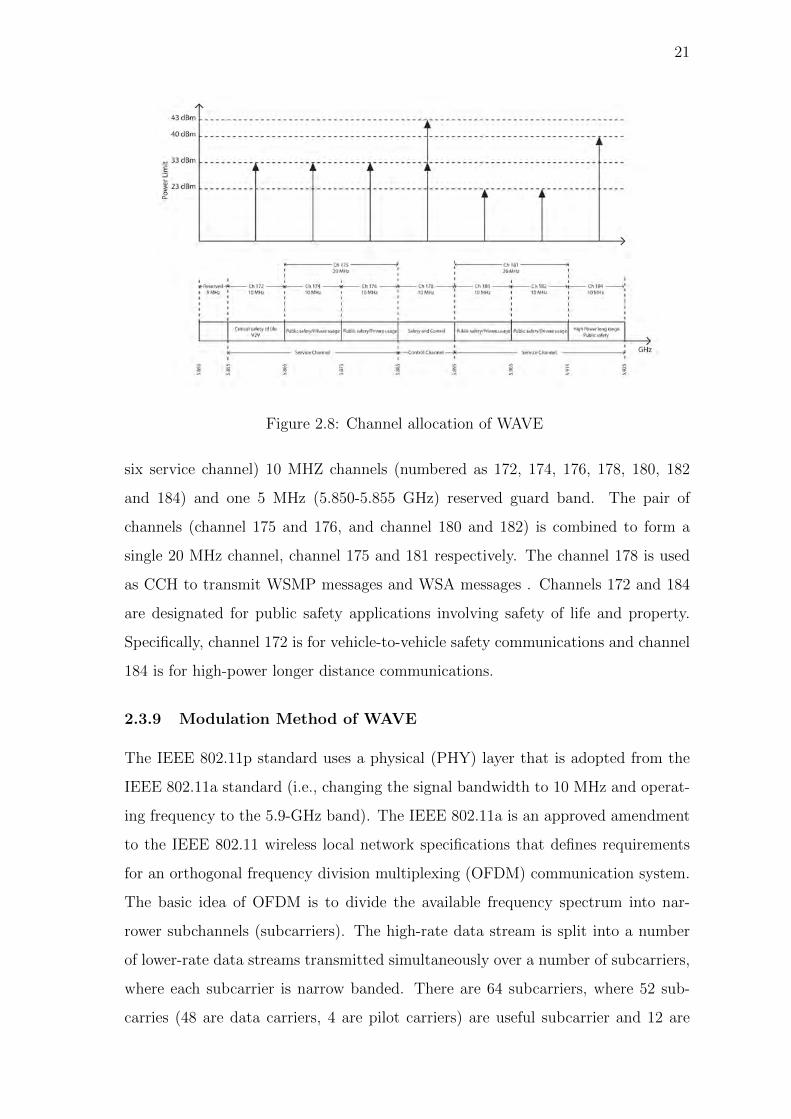
Figure 2.8: Channel allocation of WAVE
six service channel) 10 MHZ channels (numbered as 172, 174, 176, 178, 180, 182
and 184) and one 5 MHz (5.850-5.855 GHz) reserved guard band. The pair of
channels (channel 175 and 176, and channel 180 and 182) is combined to form a
single 20 MHz channel, channel 175 and 181 respectively. The channel 178 is used
as CCH to transmit WSMP messages and WSA messages . Channels 172 and 184
are designated for public safety applications involving safety of life and property.
Specifically, channel 172 is for vehicle-to-vehicle safety communications and channel
184 is for high-power longer distance communications.
2.3.9 Modulation Method of WAVE
The IEEE 802.11p standard uses a physical (PHY) layer that is adopted from the
IEEE 802.11a standard (i.e., changing the signal bandwidth to 10 MHz and operat-
ing frequency to the 5.9-GHz band). The IEEE 802.11a is an approved amendment
to the IEEE 802.11 wireless local network specifications that defines requirements
for an orthogonal frequency division multiplexing (OFDM) communication system.
The basic idea of OFDM is to divide the available frequency spectrum into nar-
rower subchannels (subcarriers). The high-rate data stream is split into a number
of lower-rate data streams transmitted simultaneously over a number of subcarriers,
where each subcarrier is narrow banded. There are 64 subcarriers, where 52 sub-
carries (48 are data carriers, 4 are pilot carriers) are useful subcarrier and 12 are

22
Figure 2.9: OFDM sub-carriers assignment as defined by IEEE 802.11p standard
null subcarriers. The null subcarries are allocated in the beginning (0) and middle
(27 to 37) of the band to eliminate the effect of null carriers in the data subcarriers.
The useful subcarriers are assigned numbers from -26 to 26. The pilot signals are
embedded into the subcarriers of -21, -7, 7 and 21 as shown in figure 2.9 .
2.4 Medium Access Control (MAC) Protocol
2.4.1 IEEE 802.11 DCF Scheme
The IEEE 802.11 standard [9] species two MAC schemes: a mandatory Distributed
Coordination Function (DCF) and an optional Point Coordination Function (PCF).
The latter is a centralized MAC protocol that provides collision free and time
bounded service. The former scheme, DCF is most widely implemented in WLAN
technologies because it is simple and offers an efficient best-effort service. The DCF
is the basic access method of the IEEE 802.11 MAC, and it is derived from carrier
sense multiple access with collision avoidance (CSMA/CA). CSMA/CA is designed
to reduce the probability of collision. The IEEE 802.11 standard specifies two ac-
cess mechanisms for DCF: basic access mechanism and RTS/CTS access mechanism.
Two-way handshaking technique is used as the basic access mechanism and four-
way handshaking technique is used as the RTS/CTS access mechanism for packet
transmission to protect hidden terminal problem.

23
2.4.1.1 Basic Access Mechanism of DCF Scheme
In the IEEE 802.11 DCF standard, the wireless nodes contend to access the shar-
ing medium using a CSMA mechanism with collision avoidance. The basic access
mechanism is described using the flow chat shown in figure 2.10. When a node
has a packet to transmit, the backoff instant enters the backoff procedure and first
selects a random backoff time from [0,W − 1], where W is the contention window
size of the node. After the channel is sensed idle for a guard time called distributed
inter-frame space (DIFS), the backoff time counter is decremented by one at the end
of each idle time slot and frozen if a packet transmission is detected by the node on
the channel. It is resumed again after the channel is sensed idle for DIFS period.
When the backoff counter reaches zero, the node transmits the packet immediately.
If ACK message returns after a short inter-frame space (SIFS), the transmission is
considered successful and the backoff instant enters the new backoff procedure with
minimum contention window size if the node already has a packet to transmit. After
each successful transmission, the backoff instant enters the post backoff procedure
if the node has no packet to transmit. The unsuccessful transmission or collision
occurs when the backoff counter of two or more nodes reach zero in the same time
slot. After every unsuccessful transmission, the backoff instant enters a new back
off procedure and doubles its contention window size. Then backoff instant selects a
random backoff time from [0, 2jW − 1], where j is the number of collision for a spe-
cific packet. The process of doubling the contention window size keeps on after each
failure until reaching a maximum, CWmax . At this stage, if the transmission failure
occurs again, the contention window is not doubled anymore. The node repeats the
last stage of backoff process at most for a predefined retry limit and drops the packet
if it has not been transmitted yet. At last, the contention window size is reset to
its minimum value for the next packet to transmit. Figure 2.11 demonstrates the
timing diagram of IEEE 802.11 DCF basic access mechanism.
2.4.1.2 Hidden Terminal Problem
Single-channel V2V and V2I networks suffer from the hidden terminal problem and
only V2V networks suffer from the exposed terminal problem. Hence, VANETs
require effective mechanisms for collision avoidance and fair contention resolution.

24
Figure 2.10: Flow chart of IEEE 802.11 DCF scheme for broadcast transmission
An example is shown in figure 2.12 to illustrate the hidden terminal problem.
vehicle Vs and Vh are the senders. Vehicle Vh is in the range of the Vehicle Vr
but cannot hear Vehicle Vs. When both, vehicle Vs and vehicle Vh want to send
packets to their common neighbor vehicle Vd, collisions occur at Vd and it hears only
garbled frames. In addition, it is generally seen that even the provision of ”sensing
the common channel before an attempt to access the channel” does not eliminate
collisions. Thus, there is degradation in the performance of the network due to a

25
Figure 2.11: Basic access mechanism of IEEE 802.11 DCF scheme
reduction in the network capacity for transmission of useful data. This scenario
is referred to as the hidden terminal problem. It is said that vehicle Vh a hidden
terminal from vehicle Vs. The hidden node problem causes unfairness in wireless
networks.
2.4.1.3 RTS/CTS Access Mechanism of DCF Scheme
DCF defines an optional RTS/CTS mechanism which can reduce the probability
of collisions caused by the hidden node problem. Figure 2.14 illustrates the timing
diagram of RTS/CTS exchange scheme. The RTS/CTS mechanism is a four-way
handshaking mechanism. A node needs to follow the medium access rules explained
in 802.11 MAC layer when it has a packet to transmit. However, before sending a
Figure 2.12: Hidden terminal problem in V2V network environment

26
Figure 2.13: Hidden terminal problem in V2I network environment
data packet, this node needs to send a special short frame which is called a Request
to Send (RTS). When the destination node receives this RTS frame, it will send
back a Clear to Send (CTS) frame after a short period of time (SIFS – Short Inter
Frame Space). The sending node can only transmit this data packet after it receives
the CTS frame correctly. The NAV (Network Allocation Vector) is the duration
of time that predicts how long the medium will be occupied for the transmission.
NAV is contained in the MAC header of the RTS/CTS frame. All nodes (except
the sender and the receiver) should update their NAV after receiving the RTS/CTS
frames. These nodes are not allowed to sense the medium status until their NAVs
are expired.
The following example explains the procedure of the RTS/CTS mechanism and
presents how the RTS/CTS mechanism to solve the hidden node problem: Vs will
send a RTS frame before starting a transmission to Vr. Even though Vh cannot hear
this RTS frame, Vr.still can hear a CTS frame from Vs. This CTS frame contains the
duration of the transmission from Vs to Vr. Vh knows the medium will be occupied
by other nodes, and Vh will defer its transmission until the duration is over [9].
The RTS/CTS mechanism can effectively ameliorate the hidden node problem,
but the RTS/CTS mechanism is not used for every data frame transmission be-
cause the RTS/CTS frame exchange will cause additional transmission overhead.
To mitigate the effect of the transmission overhead of RTS/CTS, IEEE 802.11 MAC
protocol defines the RTS/CTS exchange as an optional mechanism. The use of the
RTS/CTS mechanism is configured by the RTS threshold. If the length of the data

27
Figure 2.14: RTS/CTS access mechanism of IEEE 802.11 DCF scheme
frame is longer than the RTS threshold, the RTS/CTS mechanism will be turned
on; otherwise, the RTS/CTS mechanism will be turned off. In most IEEE 802.11
WLANs, a large value is set as the RTS threshold (e.g., 3000 octets) to disable the
RTS/CTS mechanism.
2.4.1.4 Exposed Terminal Problem
To understand the exposed terminal problem, consider Vehicle Ve which is in the
range of the transmitter Vehicle Vs, but not that of receiver Vehicle Vd1. This is
shown in Figure. With the regular carrier sensing mechanism, Vehicle Ve will defer
from accessing the shared channel when Vs attempts to transmit to Vd1. Thus Vehicle
Ve is prevented from transmitting. Vehicle Ve is the exposed terminal whose trans-
mission to Vd2 is deferred. Collision is an important design challenge for VANET.
At the time of collision, considerable amount of radio resources are wasted. This
is because the source vehicle still continues to transmit the packet completely. The
performance degradation due to these collisions tends to become more severe as the
frame size increases, since the bandwidth wasted by collisions becomes relatively
large. Hence, the amount of resources wasted in an ad-hoc network depends upon
the size of the packet. Moreover, collisions cause retransmissions. This consumes a
significant amount of energy, thus reducing the lifetime of battery-powered wireless
devices. The problem of collision is worse in a multi-hop environment than in a
single-hop environment. Collision Avoidance is implemented in the medium access
control (MAC) layers.

28
Figure 2.15: Exposed terminal problem for V2V network environment
2.4.2 IEEE 802.11p EDCF Scheme
The IEEE 802.11p standard uses a medium access control (MAC) layer that is
adopted from the IEEE 802.11e EDCA standard. The IEEE 802.11e EDCA [8] is
an extension to IEEE 802.11 DCF that provides service differentiation and quality
of services (QoS). In EDCA, the node separates its arrival traffic into four cate-
gories, each one called an Access Category (AC). Each AC, numbered from 0 to 3,
Figure 2.16: Architecture of IEEE 802.11p MAC channel coordination for multi-
channel operation

29
has its own EDCA parameters, that is, inter-frame space duration, minimum con-
tention window size, maximum contention window size, maximum backoff stages,
retransmission limit, etc. The AC0 is the lowest priority class of service and AC3
is the highest priority class of services. AC3 is served before the others and AC0 is
served after the others. Each AC queue works as an independent DCF node with
enhanced distributed channel access function (EDCAF) to contend for Transmission
Opportunities (TXOP) using its own EDCA parameters. Prioritization of transmis-
sion in EDCA is implemented by a new inter-frame space (IFS) called Arbitration
Inter-Frame Space (AIFS) used in place of DIFS. AIFS is a function of the AC i.e.,
AIFS(AC)=SIFS+AIFSN(AC)× Tslot ,where AIFSN(AC) is an integer denoting the
AIFS number of the corresponding AC, Tslot denotes the duration of a time slot and
SIFS is the short inter-frame space. Each node has four AC queues acting as four
independent nodes. At first node separates its arrival traffic into four ACs and then
place into corresponding AC queue. If the channel is sensed idle for the duration of
AIFS[x] and if the ACx queue has no data for transmission, the backoff instant does
not enter the backoff procedure. Otherwise, the backoff instant enters the back-
off procedure and first selects a random backoff time from [0,W [ACx] − 1], where
W [ACx] is the contention window size of the access category x (ACx). After AIFS[x]
time, the backoff time counter is decremented by one at the end of each idle time
slot and frozen if a packet transmission is detected by the node on the channel. It is
resumed again after the channel is sensed idle for AIFS[x] period. When the backoff
counter reaches zero and no other packet from a higher priority category is ready to
be transmitted, the node transmits the packet immediately. If the transmission is
successful and the backoff instant enters the new backoff procedure with minimum
contention window size if the AC already has a packet to transmit. If there is such
a coincidence, the packet with higher priority is transmitted while the lower priority
packet (s) experience a virtual/internal collision, that is, the packets in lower prior-
ity queues act as if a collision occurs. A scheduler inside nodes will avoid this kind
of internal/virtual collision by granting the EDCF-TXOP to the highest priority
AC. At the same time, the other colliding ACs will invoke the backoff procedure
due to the internal collision and behave as if there were an external collision on the
wireless medium. An external collision occurs when more than one AC is granted

30
Figure 2.17: A simple illustration of a V2I environment of VANET
TXOPs by different nodes. After every unsuccessful transmission, the backoff in-
stant of each ACs enters a new back off procedure and selects a random backoff time
from [0, 2jW [ACx]− 1], where j is the number of collision for a specific packet and
repeats the above procedure until it reaches the maximum retransmission limit.
2.5 Fairness in Resource Allocation
Fairness is a broad concept of communication systems. Ideally, every node of the
network would get the desired service at desired time what they want without dis-
turbing others. However, the real world is not ideal and network congestion does
occur, particularly in wireless networks where network capacity has a strict upper
limit. When congestion occurs, different nodes might not get what they want, in
terms of throughput or delay. The consequence of an unfair resource allocation
among different individuals may lead to resource starvation, resource wastage or
redundant allocation. The reasons of unfairness problem are unfair allocation of
bandwidth, unfair allocation of channel access time, link quality variation, collision
of data and different priority of data.

31
2.5.1 Different forms of fairness definition
Equal opportunity provided to the individuals in resource sharing may not mean
equal allocation of resources. On the other hand, a fair allocation may be an outcome
of a process where individuals do not have equal opportunity. Therefore, targeted
and resultant fairness may not be the same. Fairness can also be considered from the
point of view of both, system and individuals. Moreover, individuals of a system may
have to carry out various tasks in which case fairness can be defined per task [52].
Thus in this section, we dwell on these concerns and classify the fairness definitions
by providing simple but illustrative examples based on the scenario shown in figure
2.17.
2.5.1.1 Targeted and Resultant Fairness
From the point of view of resource allocation and utilization, fairness can be divided
into two types: targeted fairness and resultant fairness. Targeted fairness try to
achieve fair sharing of resources but resultant fairness aims at fair utilization. Taking
figure 2.17 as an example, all vehicles are of the same priority. When each vehicle is
assigned the same bandwidth, targeted fairness is achieved. However, if the quality
of Link L2 is worse than that of L1 , it takes longer time for V2 than V1 to access
the Internet, which means that V1 and V2 do not gain the fair access in the view of
resultant fairness.
2.5.1.2 Short-term and Long-term Fairness
Considering the time period, fairness can be categorized into short-term and long-
term. Short-term fairness focuses on resource allocation in a very short time period.
In contrast, long-term fairness measures the resource allocation over a longer time
period or at the end of the life cycle. For example in figure 2.17, all vehicles are
assumed to have the same priority. Let us say that at 12:00 each node gets 20%
of the network capacity, then they reach the short-term fairness at this moment.
However, during the previous hour, average capacity of allocation were 10%, 20%,
30%, 5% and 35%, implying that long-term fairness has not been achieved in this
period.

32
2.5.1.3 System and Individual Fairness
Fairness can be considered both on the system and individual level. The system
fairness addresses the overall fairness amongst all individuals in the system, and
individual fairness indicates whether a certain individual is treated fairly by the
system. For example in figure 2.17, the system fairness of network capacity can be
defined as equal allocation (every vehicle gets 20%). However, vehicle V1 can be
considered to achieve individual fairness when it gets 20% of the network capacity
without the concerns of other vehicles.
2.5.2 Different Forms of Fairness Measurement
Definition of fairness might be different depending on circumstances and preferences.
In wireless communication, it is important to know what is perceived as fair in
congestion situation varies. It is also important to distinguish what kind of fairness
is looked at and how it is measured [53]. Fairness measures are tools to measure
fairness level. In section 2.5.3, the most used quantitative/absolute (Jain’s index
and entropy) and qualitative/relative (max-min and proportional fairness) fairness
measures are described.
2.5.2.1 Quantitative/Absolute Fairness Measure and Qualitative/Relative
Fairness Measure
Fairness can be absolute or relative. Absolute fairness means that each node gets the
exact same amount of time, throughput or any other desired measure of resources.
However, this is often not a very useful measure, since different traffic types have
different requirements. Relative fairness is a better way of measuring fairness. Rela-
tive fairness takes into account how much of your individual requirements are being
fulfilled. The overall relative fairness can be calculated by comparing how much of
individual requirements are being fulfilled. Fairness that uses time as a measurement
unit is called temporal fairness.
2.5.2.2 Utility Fairness Measure and Cost Fairness Measure
Utility based fairness criteria defines a utility function that describes the utility a
node gets from the network with a certain capacity share. It aims to maximize the

33
total utility of all nodes. Max-min fairness, proportional fairness are special case of
utility fairness.
Utility fairness are mostly focused on node rate fairness. In [54], author criticizes
this view and says that it is myopic. It is claimed that since schemes based on node
rate do not take into account how many nodes create or how long nodes last it would
be better to focus on cost fairness. By cost fairness author means sharing out the
cost of one node’s actions on others.
2.5.3 Fairness Measurement Schemes
Some notion of fairness is incorporated in many network mechanisms used today.
This section presents some well known fairness schemes that are used to measure
fairness of the network from different point of view.
2.5.3.1 Jain’s Fairness Index
A well-known index of fairness was proposed by Jain et al. [55]. If the amount
of contending nodes is n and ith node receives an allocation xi then Jain’s fairness
index f(x) is
f(x) =[∑n
i=1 xi]2
n∑n
i=1 x2i
(2.1)
The result is the measure of equality of the allocation of values. The index gets
values between 0 and 1. When all the nodes receive an equal share i.e. the system
is completely fair, the index gets value 1. Four cases based on the scenario in figure
2.17 are given in table 2.1. As fairness decreases the index value decreases until it
reaches 0.
Table 2.1: Example of Jain’s index
Case 1 Case 2 Case 3 Case 4
V1 0% 5% 10% 20%
V2 5% 40% 30% 20%
V3 30% 50% 30% 20%
V4 0% 5% 10% 20%
V5 65% 0% 20% 20%
f(x) 0.3883 0.4819 0.8333 1

34
2.5.3.2 Entropy
Entropy function introduced by Shannon is used as a absolute fairness measure
[56]. It is assumed that the proportions of resource are allocated to n vehicles
P = (p1, p2, p3, . . . . . . . . . , pn) and
pi =xi∑ni=1 xi
(2.2)
where, 0 ≤ pi ≤ 1 (i = 1, 2, 3, . . . . . . . . . . . . , n) and∑n
i=1 pi = 1. The uncertainty of
the distribution p is called the entropy of the distribution P and is usually measured
by H (p) = H (p1, p2, p3, . . . . . . . . . . . . , pn) as given below. When H (p) used as
a fairness measure, is similar to f(x) . Only the absolute resource values of x are
replaced by resource proportions p.
H (p) =n∑
i=1
(pilog2
1
pi) (2.3)
Four cases based on the scenario in figure 2.17 are given in table 2.2. Here, it
turns out that entropy is larger when the allocations are fairer.
Table 2.2: Example of entropy
Case 1 Case 2 Case 3 Case 4
V1 1% 5% 10% 20%
V2 4% 40% 30% 20%
V3 30% 50% 30% 20%
V4 1% 4% 10% 20%
V5 64% 1% 20% 20%
H(p) 1.2518 1.4971 2.1710 2.3219
2.5.3.3 Max-min Fairness
A famous fairness scheme in networking is max-min fairness. It means that nodes
having small number of packets can fulfill all they demand while nodes having large
number of packets have to share the remainder of the capacity equally. Starting
from the node having small number of packets, the bandwidth is distributed so that

35
all nodes receive what they need until bandwidth is exhausted. In the case the nodes
that are not receiving all they require, they have to divide the capacity [57].
2.5.3.4 Proportional Fairness
Proportional fairness tries to maintain a balance between maximizing the network
throughput and allowing nodes to have at least a minimal level of service. This
criterion also favors nodes having small number of packets, but not as much as
max-min fairness. A case of proportionally fair scheduling is weighted fair queuing
(WFQ) that was introduced by Demers et al. [58]. It aims to ensure that a router’s
capacity is fully utilized. Low volume traffic is scheduled first and high volume
traffic shares the remaining bandwidth according to weights assigned [59]. In this
thesis work, proportional fairness is considered to ensure fair transmission of packet
by different velocity vehicles to support both safety and non-safety applications.
2.6 Summary
This chapter gives an overview of WAVE, application of VANET, IEEE 802.11
channel access mechanism and different types of measurement scale of fairness.

36
Chapter 3
Proposed MAC Protocol for Provisioning Fairness
in Vehicle to Infrastructure Communications
3.1 Introduction
VANET is used for both safety and non-safety applications. It contains primarily
two types of data: safety applications data and non-safety applications data. Abso-
lute fairness is applicable to the network where same type and same priority data to
be transmitted. If all the individual nodes can transmit same amount of data, then
absolute fairness is ensured. Relative fairness is applicable to the network where
some special conditions would be satisfied. If individual requirements of the nodes
are being fulfilled, then relative fairness is ensured. There are two popular rela-
tive fairness is: Max-min fairness and proportional fairness. In this research work,
proportional fairness is considered. Since VANET has two types of data, absolute
fairness is not applicable for VANET. The requirements of the proportional fairness
is high velocity vehicles can be transmitted a minimum number of packets to fulfill
safety application and other (medium and low velocity) vehicles can be transmitted
a certain amount of data which is proportional to the individual residence time.
To ensure proportional fairness, dynamic allocation of batch number and dynamic
allocation of MAC parameters to the vehicles is performed based on their residence
time. Minimum packets transmission of the high velocity vehicles is ensured by set-
ting low minimum contention window size compare with medium and low velocity
vehicles. Number of packets transmission is proportional to residence time is en-
sured by updating batch number dynamically based on residence time. Low velocity
vehicles can transmit packet under three batches and medium velocity vehicles can
transmit packet under two batches. In this way, number of packets transmission is

37
proportional to the residence time is achieved by the proposed protocol.
IEEE 802.11p standard [8] is an approved amendment of IEEE 802.11 standard
and completely decentralized MAC protocol which is only design to support broad-
cast in short distance V2V communication [60]. This approach is vulnerable to the
hidden terminal problem because it cannot use the request to send (RTS)/clear to
send (CTS) for packet broadcasting. Due to absence of acknowledge (ACK), reliable
and guaranteed transmission is not properly ensured. Exponential bachoff scheme
that extends the CW size for decreasing the probability of collision is not used in this
protocol [4, 5, 30,61,62]. Due to lack of centralized control in V2V, synchronization
among vehicles with SI is a difficult task. It is not feasible to select one vehicle as
a central access point using a head selection algorithm when vehicles may join or
leave the network at a fast rate [63]. In a typical VANET, RSU may offer directly
various forms of ITS services to the vehicles using V2I communication [64,65].
3.2 System Model
In this research work a simple traffic model is considered for vehicles moving along
a straight road with both directions covered by one AP or RSU at a fixed position
on the road divider, as shown in figure 3.1.
The research work assumes that the vehicles arrive in the network according to a
Figure 3.1: A V2I based VANET model

38
Poisson process and no transmission error due to defective channel. Each vehicle has
two queues: one for safety applications and other for non-safety applications. Two
queues are contending independently to access physical medium. The architecture
of MAC channel coordination for multichannel operation is shown in figure 3.2.
The links between vehicle and RSU both are symmetric and the effect of hidden
terminals, exposed terminals and channel capture are ignored. In the coverage area,
the vehicles may change the moving direction and velocity. Each vehicle must have
capacity to measure its position, moving direction and velocity. The network has
three classes of vehicles which are grouped according to residence time.
Figure 3.2: Proposed architecture of IEEE 802.11 DCF MAC channel coordination
for multi-channel operation

39
3.3 Proposed MAC Protocol
The proposed IEEE 802.11 DCF based MAC protocol is a channel access mechanism
designed for avoiding unfairness problem at the MAC layer. It defines three class
of vehicles in whole network covered by a RSU and denoted by Batch 1, Batch
2 and Batch 3. Each batch vehicles has a queue independently contending for
transmission with its own MAC parameters, including minimum contention window
(CWmin(i)), maximum contention window (CWmax(i)), maximum backoff stage(mi)
and the retransmission limit value (mi + xi), where i denote the batch number of
the vehicle. In the proposed mechanism, after entering to the network, vehicles will
continue the following steps to communicate with RSU.
1. At first every vehicles will associate with the RSU after entering into a partic-
ular coverage range of a RSU.
2. Vehicle will compute their velocity, moving direction and position in the net-
work using GPS receiver. After that, vehicles will calculate their residence
time in the network. Based on their residence time, vehicles will be associated
as a member of Batch i.
3. Every vehicle will sense the channel and if the channel is sensed idle until
more than or equal to DIFS time then it will enter to the backoff procedure
Figure 3.3: Channel access mechanism of proposed MAC protocol
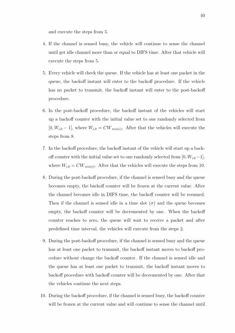
40
and execute the steps from 5.
4. If the channel is sensed busy, the vehicle will continue to sense the channel
until get idle channel more than or equal to DIFS time. After that vehicle will
execute the steps from 5.
5. Every vehicle will check the queue. If the vehicle has at least one packet in the
queue, the backoff instant will enter to the backoff procedure. If the vehicle
has no packet to transmit, the backoff instant will enter to the post-backoff
procedure.
6. In the post-backoff procedure, the backoff instant of the vehicles will start
up a backoff counter with the initial value set to one randomly selected from
[0,Wi,0 − 1], where Wi,0 = CWmin(i). After that the vehicles will execute the
steps from 8.
7. In the backoff procedure, the backoff instant of the vehicle will start up a back-
off counter with the initial value set to one randomly selected from [0,Wi,0−1],
where Wi,0 = CWmin(i). After that the vehicles will execute the steps from 10.
8. During the post-backoff procedure, if the channel is sensed busy and the queue
becomes empty, the backoff counter will be frozen at the current value. After
the channel becomes idle in DIFS time, the backoff counter will be resumed.
Then if the channel is sensed idle in a time slot (σ) and the queue becomes
empty, the backoff counter will be decremented by one. When the backoff
counter reaches to zero, the queue will wait to receive a packet and after
predefined time interval, the vehicles will execute from the steps 2.
9. During the post-backoff procedure, if the channel is sensed busy and the queue
has at least one packet to transmit, the backoff instant moves to backoff pro-
cedure without change the backoff counter. If the channel is sensed idle and
the queue has at least one packet to transmit, the backoff instant moves to
backoff procedure with backoff counter will be decremented by one. After that
the vehicles continue the next steps.
10. During the backoff procedure, if the channel is sensed busy, the backoff counter
will be frozen at the current value and will continue to sense the channel until

41
get idle channel more than or equal to DIFS time. After the channel becomes
idle in DIFS time, the backoff counter will be resumed. Then if the channel is
sensed idle in a time slot (σ), the backoff counter will be decremented by one.
When the backoff counter reaches to zero, the packet will be transmitted.
11. If the transmission is successful i.e. transmitting vehicle will receive acknowl-
edgment (ACK) successfully, the vehicle execute the steps from 2.
12. If the vehicle does not receive an ACK packet in a given time, the packet will
be retransmitted. At each retransmission, the backoff instant of the vehicle
will start up a new backoff counter with the initial value set to one randomly
selected from [0,Wi,j − 1], where Wi,j = 2j × CWmin(i) and j is the number of
retransmission. After the vehicle execute from the steps 2.
13. If the value ofWi,j reaches to CWmax(i) , the backoff instant keep the contention
window size CWmax(i). Then the vehicle will try to retransmission up to
retransmission limit (mi+xi) without change the contention window size using
step 10. After the (mi + xi + 1) times unsuccessful transmission, the packet
will be dropped and vehicle will execute the steps from 2.
14. When the residence time of the vehicle becomes zero, the vehicle will exit
from the network and continue the above procedures under the next RSU. The
channel access mechanism with batch update procedure is shown in figure 3.3.
3.4 Modeling of the Proposed MAC Protocol
3.4.1 Batch Selection
The network model described in figure 3.1 is considered in this research work and at
first the batch selection procedure of each vehicles is observed in this section. The
instantaneous residence time, Tr of a vehicle can be expressed as
Tr =R± rv
(3.1)
where, R is the radius of the coverage range of RSU, r is the instantaneous
distance of a vehicle from RSU, v is the instantaneous velocity of a vehicle, ‘+’

42
indicates the moving direction of vehicle toward to RSU and ‘-’ indicates the moving
direction of vehicle backward from RSU.
Let, the velocity of the vehicles is uniformly distributed in [vmin, vmax]ms−1.
Different residence time of the vehicles are computed as
Tr(min) =2R
vmax
(3.2)
Tr(max) =2R
vmin
(3.3)
Tr(in) =Tr(min) + Tr(max)
2(3.4)
where, Tr(min), Tr(in) and Tr(max) are minimum residence time, intermediate residence
time and maximum residence time respectively. Selection of batch of the vehicles
can be occurred by the table 3.1 after passing certain time interval.
Table 3.1: Batch selection and update
Instantaneous Residence
Time (Tr)Batch No (Bi)
Maximum Residence
Time(Tr(i))Priority
0 <Tr ≤ Tr(min) B1 Tr(min) High
Tr(min) <Tr ≤ Tr(in) B2 Tr(in) Medium
Tr(in) <Tr ≤ Tr(max) B3 Tr(max) Low
According to E. Karamad et al. [10], the packet transmission rate, Ri of a vehicle
in batch i (i = 1, 2 , 3) can be expressed as
Ri = HRbit
Nbit
Pt(i)∑3k=1 Pt(k)
(3.5)
where, H is the normalized throughput of the network, Nbit is the average number
of bits in the packet, Rbit is the bit rate over the channel and Pt(i) is the transmission
probability of the vehicle in batch i.
To avoid unfairness by ensuring minimum access, the total number of packets trans-
mitted within the average residence time of vehicle of each batch in the network is
equal to NP . Thus NP can be written as
RiTr(i) = NP (3.6)
Where, NP is the minimum number of packet transmitted by every vehicle to
ensure proportional fairness.

43
3.4.2 Markov Chain Analysis
At first a 2-D Markov chain is constructed to describe the post-backoff procedure and
backoff procedure of vehicle queue for non-saturated and saturated state respectively,
which is shown in figure 3.4. In this Markov chain, the state of each vehicle queue
is denoted by (i, j, k) , where i is just an index standing for the batch number, j is
the backoff stage number and k is the value of backoff counter. The backoff stage, j,
starts at 0 at the first attempt to transmit a packet and is increased by one every time
a transmission attempts results in a collision, up to a maximum value mi +xi . It is
reset to either 0 or e after a successful transmission or a packet drop for representing
the queue is non-empty or empty respectively. The value of k is initially set to one
that is uniformly selected from [0,Wi,j−1] once a state reaches stage j and is either
decremented by one if the channel is sensed idle in a slot or frozen if a transmission
is detected on the channel, and reactivated when the channel is sensed idle again
more than a DIFS time. Transmission is attempted when channel is sensed idle for
DIFS time after backoff counter reached to zero.
The contention window of a vehicle of batch i at the stage j is defined by
Wi,j =
CWmin(i) ; j = 0 or e
2jCWmin(i) ; 1 = j ≤ mi
CWmax(i) ; mi ≤ j ≤ mi + xi
(3.7)
At the time of backoff procedure, if the channel is sensed busy, the backoff counter
is frozen to the present backoff value and if the channel is sensed idle, the backoff
counter is decremented by one. For 0 < k = Wi,j − 1, these one-step transition
probabilities are given by
Pi,j,k | i,j,k = 1− Pidle(i) ; 0 ≤ j ≤ mi + xi (3.8)
Pi,j,k−1 | i,j,k = Pidle(i) ; 0 ≤ j ≤ mi + xi (3.9)
During the backoff procedure, after each unsuccessful transmission attempt, the
backoff instance moves down to below row at probability Pcoll(i) until reaches to
maximum retransmission limit mi + xi and chose a random backoff time at proba-
bility 1/Wi,j. For 0 <k ≤ Wi,j−1 and 0 ≤ j ≤ mi +xi−1, this one-step transition

44
Figure 3.4: Markov chain model for the backoff procedure of a vehicle with both
saturated and non-saturated state

45
probability is given by
Pi,j+1,k | i,j,0 =Pcoll(i)
Wi,j
(3.10)
After exceeding the retransmission limit, the packet is dropped at probabilityPdrop(i).
Pdrop(i) = Pmi+xi+1coll(i) (3.11)
During the backoff procedure, after each successful transmission or packet drop,
the backoff instance moves to second row at probability Psucc(i) or Pdrop(i) respectively
if there is a packet waiting in the transmission queue represented by probability
1−Peqat(i) or moves of first row if there is no packet waiting in the transmission queue
represented by the probability Peqat(i) and backoff instance enters to the post-backoff
procedure. When backoff instance reaches to the state (i, j, 0) of Markov chain, the
channel idle probability is zero. So that the probability of successful transmission is
1− Pcoll(i). For 0 ≤ k ≤ Wi,0 − 1, these one-step transition probabilities are given
by
Pi,e,k| i,j,0 =
(1− Pcoll(i)
)Peqat(i)
Wi,0
; 0 ≤ j ≤ mi + xi − 1 (3.12)
Pi,0,k| i,j,0 =
(1− Pcoll(i)
) (1− Peqat(i)
)Wi,0
; 0 ≤ j ≤ mi + xi − 1 (3.13)
Pi,e,k| i,mi+xi,0 =Peqat(i)
Wi,0
(3.14)
Pi,0,k| i,mi+xi,0 =
(1− Peqat(i)
)Wi,0
(3.15)
During the post-backoff procedure, if the channel is sensed idle and the queue is
empty, the backoff counter is decremented by one, if the channel is sensed idle and
the queue has at least one packet to transmit, the backoff counter is decrement by
one and backoff instance jump to next backoff stage, if the channel is sensed busy
and the queue is empty, the backoff counter is frozen, or if the channel is sensed busy
and the queue has at least one packet to transmit, the backoff counter is frozen and
backoff instance jump to next backoff stage. For 0<k ≤ Wi,0 − 1, these one-step
transition probabilities are given by
Pi,e,k| i,e,k = Peq(i)
(1− Pidle(i)
)(3.16)
Pi,e,k−1 | i,e,k = Peq(i)Pidle(i) (3.17)
Pi,0,k−1 | i,e,k =(1− Peq(i)
)Pidle(i) (3.18)

46
Pi,0,k| i,e,k =(1− Peq(i)
) (1− Pidle(i)
)(3.19)
When back-off instance complete the post back-off procedure then it is wait-
ing for a packet at probability Peq(i). If it receives a packet and channel is busy,
the back-off instance shift down to next back-off stage but when channel is sensed
idle and received a packet, the backoff instance moves to state (i, 0, 0) to attempt
transmission.
Pi,e,0 | i,e,0 = Peq(i) (3.20)
Pi,0,0 | i,e,0 =(1− Peq(i)
)Pidle(i) (3.21)
Pi,0,k| i,e,0 =
(1− Peq(i)
) (1− Pidle(i)
)Wi,0
; 0 ≤ k ≤ Wi,0 − 1 (3.22)
Let, a =∑mi+xi−1
j=0 Psucc(i)bi,j,0 + bi,mi+xi,0 and
b = a(1− Peqat(i)
)+(1− Pidle(i)
)(1− Peq(i))bi,e,0
According to the 2-D Markov chain in figure 3.4, all birth-death equations write
recursively through the chain from upper row to lower row and from right to left,
then the following stationary probabilities are given as follows:
bi,e,0 =aPeqat(i)
Wi,0(1− Peq(i))
1− PWi,0
eq(i)
1− Peq(i)
(3.23)
bi,0,k =b(Wi,0 − k)
Wi,0Pidle(i)
+ (1− Peq(i))Pidle(i)bi,e,k+1
+ (1− Peq(i))(1− Pidle(i))bi,e,k ; 0<k ≤ Wi,0 − 1
(3.24)
bi,j,k =Wi,j − kWi,jPidle(i)
P jcoll(i)bi,0,0 ; 0<j ≤ mi + xi (3.25)
bi,j,o = P jcoll(i)bi,0,0 ; 0 ≤ j ≤ mi + xi and 0<k ≤ Wi,0 − 1 (3.26)
Using the above equations, all stationary probabilities bi,j,k are expressed by bi,0,0
and which is finally determined by imposing the normalization condition, as follows:
Wi,0−1∑k=0
bi,e,k +
mi+xi∑j=0
Wi,j−1∑k=0
bi,j,k = 1 (3.27)
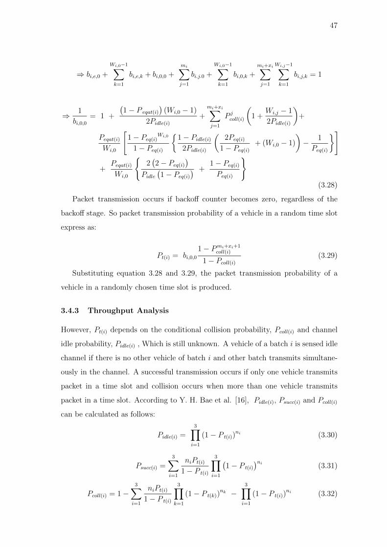
47
⇒ bi,e,0 +
Wi,0−1∑k=1
bi,e,k + bi,0,0 +
mi∑j=1
bi.j.0 +
Wi,0−1∑k=1
bi,0,k +
mi+xi∑j=1
Wi,j−1∑k=1
bi,j,k = 1
⇒ 1
bi,0,0= 1 +
(1− P eqat(i)
)(Wi,0 − 1)
2Pidle(i)
+
mi+xi∑j=1
P jcoll(i)
(1 +
Wi,j − 1
2Pidle(i)
)+
Peqat(i)
Wi,0
[1− Peq(i)
Wi,0
1− Peq(i)
{1− Pidle(i)
2Pidle(i)
(2Peq(i)
1− Peq(i)
+ (Wi,0 − 1)
)− 1
Peq(i)
}]
+Peqat(i)
Wi,0
{2(2− Peq(i)
)Pidle
(1− Peq(i)
) +1− Peq(i)
Peq(i)
}(3.28)
Packet transmission occurs if backoff counter becomes zero, regardless of the
backoff stage. So packet transmission probability of a vehicle in a random time slot
express as:
Pt(i) = bi,0,01− Pmi+xi+1
coll(i)
1− Pcoll(i)
(3.29)
Substituting equation 3.28 and 3.29, the packet transmission probability of a
vehicle in a randomly chosen time slot is produced.
3.4.3 Throughput Analysis
However, Pt(i) depends on the conditional collision probability, Pcoll(i) and channel
idle probability, Pidle(i) , Which is still unknown. A vehicle of a batch i is sensed idle
channel if there is no other vehicle of batch i and other batch transmits simultane-
ously in the channel. A successful transmission occurs if only one vehicle transmits
packet in a time slot and collision occurs when more than one vehicle transmits
packet in a time slot. According to Y. H. Bae et al. [16], Pidle(i), Psucc(i) and Pcoll(i)
can be calculated as follows:
Pidle(i) =3∏
i=1
(1− P t(i))ni (3.30)
Psucc(i) =3∑
i=1
niPt(i)
1− P t(i)
3∏i=1
(1− P t(i)
)ni (3.31)
Pcoll(i) = 1−3∑
i=1
niPt(i)
1− P t(i)
3∏k=1
(1− P t(k))nk −
3∏i=1
(1− P t(i))ni (3.32)

48
According to Bianchi model [35], the throughput of batch i of the network can
be calculated as:
Si =TpP succ(i)
TsuccPsucc(i) + TcollPcoll(i) + σPidle(i)
(3.33)
Where, Tp is the average packet length in time, σ is the time duration of an
empty slot, Tcoll is the average time containing two or more colliding packet and
Tsucc is the average time containing a successfully transmitted packet.
Time intervals Tsucc and Tcoll depend on the access method used. In the case of
the basic access method they are as follows.
Tsucc = TDIFS + TH + TDATA + TSIFS + TACK + 2δ (3.34)
Tcoll = TDIFS + TH + TDATA + TACK(timeout) + δ (3.35)
where,TACK(timeout) is assumed to be TEIFS − TDIFS.
In the case of RTS/CTS access mechanism they are as follows.
Tsucc = TDIFS+TRTS+TSIFS+TCTS+TSIFS+TH+TDATA+TSIFS+TACK+4δ (3.36)
Tcoll = TDIFS + TRTS + TCTS(timeout) + δ (3.37)
Where δ denotes the propagation delay and TH is the time required to send the
PHY and MAC headers. The TCTS(timeout) is assumed to be TEIFS − TDIFS.
3.5 Summary
This chapter presents an efficient MAC protocol to ensure the proportional fairness
of V2I network environment of VANET. The proposed protocol introduces a novel
scheme to search a minimum contention window size for provisioning proportional
fairness and a dynamic batch selection method based on the residence time.
Also a Markov Model is developed to mathematically analyze the proposed proto-
col for validation of the network performances in terms of throughput of the network.

49
Chapter 4
Results and Performance Evaluation
4.1 Introduction
In order to validate the proposal and verify its mathematical model MATLAB sim-
ulation tool is used. The MATLAB tool is very popular and efficient to verify
mathematical models. The proposed protocol is analyzed through a mathematical
model and by using MATLAB the developed equations are solved using this tool.
All the equations from the Markov Model are used in the MATLAB editor and
solved them to plot different results for the proposed protocol.
Table 4.1: System parameters
Parameter Value Parameter Value
Tp(µs) 8184 H 0.8
Tsucc(µs) 8972 Rbit(Mbps) 1
Tcoll(µs) 8713 Nbit(byte) 216
σ(µs) 50 D(m) 500
SIFS(µs) 28 NP 4000
DIFS(µs) 128 vmax(ms−1) 45
ACK(µs) 240 vmin(ms−1) 5
4.2 Analytical Results
The performance analysis of the proposed MAC protocol based on the analytical
model is carried out in this section. For simplicity, the research work assumes that
all types of vehicles transmit packets of equal lengths (216 bytes) and probabilities
(0.01) that a queue has packets waiting for transmission are equal and use basic

50
Minimum contention window size
0 5 10 15 20 25 30 35 40 45 50
Tra
nsm
issio
n p
rob
ab
ilit
y
0
0.1
0.2
0.3
0.4
0.5
0.6
0.7
Figure 4.1: Selection of minimum contention window size based on transmission
probability
access mechanism. The parameters used in the analytical experiments are listed in
table 4.1.
4.2.1 Selection of Minimum Contention Window Size
Figure 4.1 shows the relationship between the transmission probability of the vehicle
and the minimum contention window size. It is seen that minimum contention
window size increases as the transmission probability decreases. To ensure fairness,
the transmission probability of each batch is calculated by using equation 3.5 and
Table 4.2: Parameters used in numerical calculations
Parameters Batch 1 Batch 2 Batch 3
CWmin 3 9 30
CWmax 12 112 1280
mi 2 4 7
xi 4 2 0

51
3.6. The calculated transmission probability is used to determine the minimum
contention window size of each batch for further analysis and the output from the
figure 4.1 describes it as well. The maximum backoff stage and retransmission
limit of each batch is set a fixed value for simplicity. The minimum and maximum
contention window size and retransmission limit of each batch is summarized in
table 4.2.
4.2.2 Comparison of Different Probabilities of Different Batches
4.2.2.1 Channel Idle Probability
The channel idle probability of each batch under the increasing number of vehicles
in the network is shown in figure 4.2. The channel idle probability is decreases as
the number of vehicles increases for each batches. This is because as the number of
vehicles increases, more vehicles would contend for transmission in the same time
slot, resulting decrement of channel idle probability. Due to low contention window
size of high priority batch (Batch 1) compared to other batches (Batch 2 and Batch
3), the density of vehicles in a backoff stage is high for same number of vehicles,
Number of vehicles
0 10 20 30 40 50 60
Pro
bab
ilit
y o
f ch
an
nel
idle
0.3
0.4
0.5
0.6
0.7
0.8
0.9
1
Batch 1
Batch 2
Batch 3
Figure 4.2: Probability of channel idle vs number of vehicle

52
resulting in low probability of channel being idle. For Batch 1 when the number of
vehicles is less than 2, then the channel idle probability is maximum and is above
90%. This is because less vehicles tends to less contention and as a result the
network remains idle for long time. But when the number of vehicles increases,
for example 20 vehicles in the network causes channel idleness less than 45%. And
this percentage becomes more less for increasing number of vehicles. For other two
batches Batch 2 and Batch 3 this probability starts from less than 80% and 75%
respectively. For Batch 2 and Batch 3 this probability remains almost same under
varying number of nodes because of high contention window size.
4.2.2.2 Collision Probability
Figure 4.3 shows the probability of collision of each batch under different number
of vehicles in the network. From the figure 4.3 it can be seen that the probability
of collision of Batch 1 increases as the number of vehicles in the network increases.
When there are less number of vehicles the collision probability is less than 10%
for Batch 1 and the probability increases up to 22% as the number of vehicles
increases. Because more number of vehicles results more attempt to contention and
Number of vehicles
0 10 20 30 40 50 60
Pro
bab
ilit
y o
f co
llis
ion
0.05
0.1
0.15
0.2
0.25
0.3
0.35
Batch 1Batch 2Batch 3
Figure 4.3: Probability of collision vs number of vehicle

53
occurs more collision for Batch 1 as the contention window of Batch 1 vehicles is
minimum as compared to the other batches. Due to low contention window size
of high priority batch compared to other batches, high priority batch will get more
chance to transmit packet and thus will suffer less collision for low density vehicles.
For high density network, high priority batch would got more collision compared to
other batches. The collision probability for Batch 2 and Batch 3 is 22% and 27%
respectively at the initial state of the network.
4.2.2.3 Successful Transmission Probability
The probability of successful transmission of each batch under different number
of vehicles in the network is shown in figure 4.4. The probability of successful
transmission increases proportionally with the increasing number of vehicles. The
successful transmission probability of Batch 1 is much greater than other two batches
Batch 2 and Batch 3. For Batch 1 this probability is up to 35% or more under
varying number of nodes. For Batch 2 the successful transmission probability is less
compared to Batch 1, because the contention window (CW) for Batch 1 is selected
minimum to give high priority to this batch vehicle than the other batches. For
Number of vehicles
0 10 20 30 40 50 60
Pro
bab
ilit
y o
f su
ccessfu
l tr
an
sm
issio
n
0
0.05
0.1
0.15
0.2
0.25
0.3
0.35
Batch 1Batch 2Batch 3
Figure 4.4: Probability of successful transmission vs number of vehicle

54
Batch 3 vehicle the CW is maximum compared to Batch 1 and Batch 2, that’s why
the successful transmission probability of Batch 3 is minimum and is less than 5%.
This is because Batch 3 vehicles get more time to access the network and when these
vehicles enters to the high priority batches the successful transmission probability
increases also.
4.2.2.4 Packet Drop Probability
Figure 4.5 shows the probability of packet drop of each batch under different number
of vehicles in the network. This probability increases for each batch with the number
of increasing vehicles. The packet drop probability is very low for Batch 1 vehicles
and is almost zero percent when the network has minimum number of vehicles. The
probability increases when the network is populated with vehicles and the contention
increases among vehicles greatly. The packet drop probability of Batch 2 and Batch
3 is higher compared to Batch 1 at the initial state of the network. When the network
is densely populated the packet drop probability of all batch vehicles performance
is almost same.
Number of vehicles
0 10 20 30 40 50 60
Pro
bab
ilit
y o
f p
ack
et
dro
p
×10-4
0
1
2
3
4
5
6
Batch 1Batch 2Batch 3
Figure 4.5: Probability of packet drop vs number of vehicle

55
Number of vehicles
0 10 20 30 40 50 60
Pro
bab
ilit
y o
f tr
an
sm
issio
n
0
0.01
0.02
0.03
0.04
0.05
0.06
0.07
0.08
Batch 1
Batch 2
Batch 3
Figure 4.6: Probability of transmission vs number of vehicle
4.2.2.5 Transmission Probability
Transmission probability is the probability that the vehicles get the opportunity to
transmit its packets. The transmission probability of Batch 1 vehicles is better than
other batches Batch 2 and Batch 3. It is also seen from the figure 4.6 that the
transmission probability of Batch 1 is greater than other batches. This is because
Batch 1 vehicles have the high priority to access the network first and this is done
by giving them minimum CW for contention. Batch 2 and Batch 3 vehicles have
greater CW compared to Batch. Batch 2 vehicles occupied the channel for long
period of times than Batch 1 and less than batch 3 vehicles. Batch 1 vehicles get
short period of time to access the network that’s why the transmission probability
of these batch vehicles are maximum than other batches and Figure 4.6 shows the
same.

56
4.2.3 Non-saturated Normalized Throughput Evaluation
4.2.3.1 Throughput of Different Batches
Figure 4.7 shows the throughput of each batch vehicles with respect to the increasing
number of vehicles in the network. Throughput of each batch reaches a maximum
value with the increasing number of varying vehicles. The throughput for Batch 1
is close to 60% as compared to the other batches; this is because the small number
of vehicles leads to a low throughput for each vehicle. With the number of vehicles
increasing within a certain range, it may not cause many collisions, resulting in an
increase of the throughput for each batch vehicles. With the further increase in
the number of vehicles, however, more vehicles will arrive in the network and will
contend for transmission simultaneously, which would result in more collisions and
thus a reduction in the throughput for each batch vehicle. For Batch 2 and Batch
3 the throughput is close to 30% and 10% respectively.
Number of vehicles
0 10 20 30 40 50 60
No
rmali
zed
th
rou
gh
pu
t
0
0.1
0.2
0.3
0.4
0.5
0.6
Batch 1
Batch 2
Batch 3
Figure 4.7: Throughput vs number of vehicle

57
Table 4.3: Batch selection
Instantaneous Residence Time (sec) (Tr) Batch No (Bi)
0 <Tr ≤ 11.11 B1
11.11 <Tr ≤ 55.55 B2
55.55 <Tr ≤ 100 B3
4.2.3.2 Total Throughput of Vehicle
Figure 4.8 shows the total normalized throughput of vehicles with respect to the
increasing number of vehicles in the network. It is assumed that initially three types
of vehicles enter in the network with having velocities 5 ms−1, 9 ms−1 and 45 ms−1
and this is unchanged to the whole residence time. According to the batch selection
table 4.3, first type vehicles enter to the network as a member of Batch 3, second
type vehicles as a member of Batch 2 and last type vehicle as a member of Batch
1. It is observed that in figure 4.8, the vehicles which are entered to the network
as a member of Batch 3, achieve highest throughput because this vehicles get three
times (as a member of Batch 3, Batch 2 and Batch 1) chance to transmit data. The
Number of vehicles
0 10 20 30 40 50 60
No
rmali
zed
th
rou
gh
pu
t
0
0.1
0.2
0.3
0.4
0.5
0.6
0.7
0.8
0.9
1
Enter as batch 1 (low residence time)Enter as batch 2 (medium residence time)Enter as batch 3 (high residence time)
Figure 4.8: Total throughput vs number of vehicle

58
Residence time (second)
0 11.11 20 30 40 50 55.55 60 70 80 90 100
Nu
mb
er
of
tran
sm
itte
d p
ack
ets
0
2000
4000
6000
8000
10000
12000
14000
16000
Proposed MAC protocolE. Karamad and F. Ashtiani proposed MAC protocolIEEE 802.11 DCF MAC protocol
Tr(max)Tr(min)
Batch 3Batch 2Batch 1
Tr(in)
Figure 4.9: Number of transmitted packets vs residence time
vehicles which are entered to the network as a member of Batch 2, achieve second
highest throughput because this vehicles get two times (as a member of Batch 2 and
Batch 1) chance to transmit data. The vehicles which are entered to the network as
a member of Batch 1, achieve lowest throughput because it have no chance to enter
other batches. It is clear that throughput is proportional to the residence time of
the vehicles.
4.2.4 Maximum Transmitted Data of Different Protocols
Figure 4.9 shows the comparison of maximum number of transmitted packets of
different MAC protocols with various velocities under residence time. It is observed
that in IEEE 802.11 DCF MAC, variation in data transmission amount between
high and low velocity vehicles increases with velocity increment without ensuring a
minimum access for high velocity vehicles. For karamad protocol [66], the amount
of packet transmission is constant regardless of velocity variation. However, in this
research work the proposed protocol clearly demonstrates that the number of packets
transmission remain proportional to the residence time as well as a minimum channel
access for high velocity vehicles is ensured. The proposed protocol also ensures that

59
Figure 4.10: Maximum number of packet transmission vs different proposed proto-
cols with considering different velocities
the fairness for all kind of vehicles under different batches.
4.2.5 Effect of Velocity on Packet Transmission
Figure 4.10 shows the amount of maximum transmitted data (packet) under different
MAC protocols. It is seen that IEEE 802.11 DCF MAC protocol offers a maximum
transmitted data which is proportional to the residence time of the vehicles because
a common MAC parameter is used by all the vehicles. Moreover, Karamad pro-
posed MAC protocol [66] offers an equal maximum transmitted data regardless of
residence time because each batch vehicles use different MAC parameters which are
determined by considering total number of packets transmitted within the residence
time of each batch in the network should be equal.
4.3 Summary
This chapter presents the graphical representation of the proposed protocol and
compare with different protocols. The proposed protocol ensure the proportional
fairness i.e. all vehicles must transmit a minimum number of packets and amount
of maximum transmitted data is proportional to their residence time. The proposed
protocol ensures better fairness than IEEE 802.11 DCF and Karamad’s protocol
compared with number of maximum transmitted data.

60
Chapter 5
Conclusion and Future Work
5.1 Conclusion
In vehicular ad-hoc networks, unfairness problem arises due to the varying resi-
dence time of the vehicles. In this thesis work considering this problem, an efficient
MAC protocol based on 802.11 DCF is proposed which adapts the MAC parame-
ters of each vehicle according to its residence time and updates the MAC param-
eters after certain time interval. Every vehicle has the chance to adapt at least
higher priority MAC parameters. As a result, fairness in the sense of minimum
chance of communicating with RSU for the vehicles having minimum residence time
and time proportional chance of communicating with RSU for the other vehicles is
achieved. Furthermore, An analytical models is developed to analyze the perfor-
mance of the proposed MAC protocol in a non-saturated state taking into account
all major factors that could affect the access performance of the proposed MAC
protocol, including the saturation condition, backoff counter freezing, channel idle,
collision, successful transmission, packet drop and retransmission limit . Based on
the analytical model, relation between the transmission probability and minimum
contention window size, and the relationship between number of vehicles and some
other important parameters including probability of collision, probability of packet
drop, probability of channel idle, probability of successful transmission, probability
of transmission and throughput is derived. Moreover, it is shown that the value
of MAC parameters can be determined for a given velocity in order to achieve fair
access. Finally, the relationship between maximum transmitted data and residence
time of the vehicles to compare the performance of the proposed MAC protocol with
basic access mechanism IEEE 802.11 DCF MAC and E. Karamad MAC protocol is

61
explored. Accordingly, the proposed MAC protocol overcomes the unfairness prob-
lem by ensuring minimum access of all the vehicles for both safety and non-safety
applications.
5.2 Future Work
The proposed protocol ensures the proportional fairness of V2I communication with-
out QoS. In future the research work will be proposed a MAC protocol to ensuring
proportional fairness for V2V and V2I communication with QoS and the perfor-
mance is analyzed by both analytical model and simulation environment.

62
Bibliography
[1] L. Zheng, Y. Wu, Z. Xu, and X. Lin, “A Novel MAC Protocol for VANET based
on Improved Generalized Prime Sequence,” in Advanced Infocomm Technology
(ICAIT), 2014 IEEE 7th International Conference on, pp. 1–7, Nov. 2014.
[2] A. N. Dharsandiya and R. M. Patel, “A review on MAC Protocols of Vehic-
ular Ad Hoc Networks,” in Wireless Communications, Signal Processing and
Networking (WiSPNET), International Conference on, pp. 1040–1045, Mar.
2016.
[3] “Medium access control protocols for safety applications in vehicular ad hoc
network: A classification and comprehensive survey,”
[4] X. Jiang and D. H. Du, “PTMAC: A Prediction-Based TDMA MAC Protocol
for Reducing Packet Collisions in VANET,” IEEE Transactions on Vehicular
Technology, vol. 65, no. 11, pp. 9209–9223, Nov. 2016.
[5] “A reliable token-based mac protocol for v2v communication in urban vanet,”
[6] “Vehicular ad hoc networks: An information-centric perspective,”
[7] 3rd Generation Partnership Project (3GPP), Technical Report (TR): Study on
LTE-based V2X services (Release 14) – Technical Specification Group Service
and System Aspects (TSG SA). 2016.
[8] I. C. S. L. S. Committee et al., “IEEE Standard for Information Technology
Telecommunications and Information Exchange between Systems-Local and
Metropolitan Area Networks-Specific Requirements Part 11: Wireless LAN
Medium-Access Control (MAC) and Physical Layer (PHY) Specifications,”
IEEE Std 802.11p, 2002.

63
[9] “IEEE Standard for Information Technology — Telecommunications and Infor-
mation Exchange between Systems Local and Metropolitan Area Networks —
Specific Requirements - Part 11: Wireless LAN Medium Access Control (MAC)
and Physical Layer (PHY) Specifications,” in IEEE Std 802.11, 2016.
[10] E. Karamad and F. Ashtiani, “A modified 802.11-based MAC Scheme to Assure
Fair Access for Vehicle to Roadside Communications,” Computer communica-
tions, vol. 31, no. 12, pp. 2898–2906, Jul. 2008.
[11] P. E. Engelstad and O. N. Østerbø, “Non-saturation and Saturation Analysis
of IEEE 802.11e EDCA with Starvation Prediction,” in Proceedings of the 8th
ACM international symposium on Modeling, analysis and simulation of wireless
and mobile systems, pp. 224–233, Oct. 2005.
[12] D. Malone, K. Duffy, and D. Leith, “Modeling the 802.11 Distributed Coor-
dination Function in Non-saturated Heterogeneous Conditions,” IEEE/ACM
Transactions on networking, vol. 15, no. 1, pp. 159–172, Feb. 2007.
[13] K. Duffy, D. Malone, and D. J. Leith, “Modeling the 802.11 Distributed Coor-
dination Function in Non-saturated Conditions,” IEEE communications letters,
vol. 9, no. 8, pp. 715–717, Aug. 2005.
[14] T. H. Luan, X. Ling, and X. Shen, “MAC Performance Analysis for Vehicle to
Infrastructure Communication,” in Wireless Communications and Networking
Conference (WCNC), 2010 IEEE, pp. 1–6, Apr. 2010.
[15] T. O. Kim, K. J. Kim, and B. D. Choi, “Performance Analysis of IEEE 802.11
DCF and IEEE 802.11e EDCA in Non-saturation Condition,” IEICE transac-
tions on communications, vol. 91, no. 4, pp. 1122–1131, Apr. 2008.
[16] Y. H. Bae, K. J. Kim, M.-N. Moon, and B. D. Choi, “Analysis of IEEE 802.11
Non-saturated DCF by Matrix Analytic Methods,” Annals of Operations Re-
search, vol. 162, no. 1, pp. 3–18, Sep. 2008.
[17] “A near collision free reservation based mac protocol for vanets,”

64
[18] R. Zou, Z. Liu, L. Zhang, and M. Kamil, “A Near Collision Free Reservation
Based MAC Protocol for VANETs,” in Wireless Communications and Network-
ing Conference (WCNC), 2014 IEEE, pp. 1538–1543, 2014.
[19] W.-d. YANG, L. Pan, H.-s. ZHU, et al., “Adaptive TDMA Slot Assignment
Protocol for Vehicular Ad Hoc Networks,” The Journal of China Universities
of Posts and Telecommunications, vol. 20, no. 1, pp. 1125–18, Feb. 2013.
[20] R. Zhang, X. Cheng, L. Yang, X. Shen, and B. Jiao, “A Novel Centralized
TDMA-based Scheduling Protocol for Vehicular Networks,” IEEE Transactions
on Intelligent Transportation Systems, vol. 16, no. 1, pp. 411–416, Feb. 2015.
[21] J. Liu, F. Ren, L. Miao, and C. Lin, “A-ADHOC: An Adaptive Real-time
Distributed MAC Protocol for Vehicular Ad Hoc Networks,” Mobile Networks
and Applications, vol. 16, no. 5, pp. 576–585, Oct. 2011.
[22] H. Yu, Z. He, and K. Niu, “STDMA for Vehicle to Vehicle Communication
in a Highway Scenario,” in Microwave, Antenna, Propagation and EMC Tech-
nologies for Wireless Communications (MAPE), 2013 IEEE 5th International
Symposium on, pp. 133–138, Oct. 2013.
[23] T.-L. Sheu and Y.-H. Lin, “A Cluster-based TDMA System for Inter-Vehicle
Communications,” J. Inf. Sci. Eng., vol. 30, no. 1, pp. 213–231, Jan. 2014.
[24] M. S. Almalag, S. Olariu, and M. C. Weigle, “TDMA Cluster-based MAC for
VANETs (TC-MAC),” in World of Wireless, Mobile and Multimedia Networks
(WoWMoM), 2012 IEEE International Symposium on a, pp. 1–6, Jan. 2012.
[25] S. Bharati and W. Zhuang, “CAH-MAC: Cooperative ADHOC MAC for Vehic-
ular Networks,” IEEE Journal on Selected Areas in Communications, vol. 31,
no. 9, pp. 470–479, Sep. 2013.
[26] F. Yu and S. Biswas, “A Self Reorganizing MAC Protocol for Inter-vehicle
Data Transfer Applications in Vehicular Ad Hoc Networks,” in Information
Technology,(ICIT 2007). 10th International Conference on, pp. 110–115, Dec.
2007.

65
[27] F. Borgonovo, A. Capone, M. Cesana, and L. Fratta, “ADHOC MAC: New
MAC Architecture for Ad Hoc Networks Providing Efficient and Reliable Point-
to-point and Broadcast Services,” Wireless Networks, vol. 10, no. 4, pp. 359–
366, Jul. 2004.
[28] Y. Gunter, B. Wiegel, and H. P. Grossmann, “Cluster-based Medium Access
Scheme for VANETs,” in Intelligent Transportation Systems Conference, 2007.
ITSC 2007. IEEE, pp. 343–348, Sep. 2007.
[29] M. Hadded, P. Muhlethaler, A. Laouiti, R. Zagrouba, and L. A. Saidane,
“TDMA-based MAC Protocols for Vehicular Ad Hoc Networks: A Survey,
Qualitative Analysis, and Open Research Issues,” IEEE Communications Sur-
veys & Tutorials, vol. 17, no. 4, pp. 2461–2492, Jun. 2015.
[30] W. Alasmary and W. Zhuang, “Mobility Impact in IEEE 802.11p Infrastruc-
tureless Vehicular Networks,” Ad Hoc Networks, vol. 10, no. 2, pp. 222–230,
Mar. 2012.
[31] Q. Wu and J. Zheng, “Performance Modeling of IEEE 802.11 DCF Based Fair
Channel Access for Vehicular to Roadside Communication in a Non-saturated
State,” in Communications (ICC), 2014 IEEE International Conference on,
pp. 2575–2580, Jun. 2014.
[32] V. P. Harigovindan, A. V. Babu, and L. Jacob, “Ensuring Fair Access in
IEEE 802.11p-Based Vehicle to Infrastructure Networks,” EURASIP Journal
on Wireless Communications and Networking, vol. 2012, no. 1, pp. 168–185,
Dec. 2012.
[33] M. Hoeft and J. Rak, “How to Provide fair Service for V2I Communications in
VANETs?,” Ad Hoc Networks, vol. 37, pp. 283–294, Feb. 2016.
[34] L. Zhang, Y. Liu, Z. Wang, J. Guo, and Y. Huo, “Mobility and QoS Ori-
ented 802.11 p MAC Scheme for Vehicle to Infrastructure Communications,”
Telecommunication Systems, vol. 60, no. 1, pp. 107–117, Sep. 2015.

66
[35] G. Bianchi, “Performance Analysis of the IEEE 802.11 Distributed Coordina-
tion Function,” IEEE Journal on selected areas in communications, vol. 18,
no. 3, pp. 535–547, Mar. 2000.
[36] D. Jiang, V. Taliwal, A. Meier, W. Holfelder, and R. Herrtwich, “Design of 5.9
GHz DSRC-based Vehicular Safety Communication,” IEEE Wireless Commu-
nications, vol. 13, no. 5, Oct. 2006.
[37] F. C. Commission et al., “FCC 99-305,” FCC Report and Order, Oct. 1999.
[38] C. V. S. C. Consortium et al., “Vehicle Safety Communications Project: Task
3 Final Report: Identify Intelligent Vehicle Safety Applications Enabled by
DSRC,” National Highway Traffic Safety Administration, US Department of
Transportation, Washington DC, Mar. 2005.
[39] U. S. D. of Transportation, Report to Congress on the National Highway Traffic
Safety Administration ITS Program: Program Progress During 1992-1996 and
Strategic Plan for 1997-2002. 1997.
[40] ASTM, “ASTM E2213-03, Standard specification for telecommunications and
information exchange between roadside and vehicle systems – 5 GHz band ded-
icated short range communications (DSRC) medium access control (MAC) and
physical layer (PHY) specifications ASTM E2213-03,” 2010.
[41] IEEE, “IEEE std. 1455-1999 - IEEE Standard for Message Sets for Vehi-
cle/Roadside Communications,” 2006.
[42] D. SAE, “J2735 Dedicated Short Range Communications (DSRC) Message Set
Dictionary,” Society of Automotive Engineers, DSRC Committee, Apr. 2009.
[43] D. SAE, “Draft DSRC Message Communication Minimum Performance Re-
quirements - Basic Safety Message for Vehicle Safety Applications,” Society of
Automotive Engineers, DSRC Committee, Apr. 2011.
[44] ISO, “ISO 21217:2014 Intelligent Transport Systems – Communications Access
for Land Mobiles (CALM) – Architecture,” Apr. 2014.

67
[45] ISO, “ISO 21215:2010 Intelligent Transport Systems – Communications Access
for Land Mobiles (CALM) – M5,” 2010.
[46] ISO, “ISO 29281-1:2013 Intelligent Transport Systems – Communication Access
for Land Mobiles (CALM) – Non-IP Networking – Part 1: Fast Networking &
Transport Layer Protocol (FNTP),” Apr. 2013.
[47] E. Commission, “M/453 Standardisation Mandate Addressed to CEN, CEN-
ELEC,and ETSI in the Field of Information and Communication Technologies
to Support the Interoperability of Cooperative Systems for Intelligent Transport
in the European Community,” Jun. 2009.
[48] ETSI, “ETSI TS 102 792 V1.2.1, Intelligent Transport Systems (ITS); Mitiga-
tion Techniques to Avoid Interference between the European CEN Dedicated
Short Range Communication (CEN DSRC) and Intelligent Transport Systems
(ITS) Operating in the 5 GHz Frequency Range,” Jun. 2015.
[49] ETSI, “Draft ETSI EN 302 571 V2.0.0, Intelligent Transport Systems
(ITS);Radio Communications Equipment Operating in the 5855 MHz to 5925
MHz Frequency Band; Harmonised Standard Covering the Essential Require-
ments of Article 3.2 of Directive 2014/53/EU ,” Mar. 2016.
[50] S. A. Mohammad, A. Rasheed, and A. Qayyum, “VANET Architectures and
Protocol Stacks: A Survey,” in International Workshop on Communication
Technologies for Vehicles, pp. 95–105, Mar. 2011.
[51] I. V. T. Society, 1609.0-2013 - IEEE Guide for Wireless Access in Vehicular
Environments (WAVE) - Architecture. Mar. 2014.
[52] H. Shi, R. V. Prasad, E. Onur, and I. Niemegeers, “Fairness in Wireless Net-
works: Issues, Measures and Challenges,” IEEE Communications Surveys &
Tutorials, vol. 16, no. 1, pp. 5–24, Jan 2014.
[53] A. Matinlauri, “Fairness and Transmission Opportunity Limit in IEEE 802.11e
Enhanced Distributed Channel Access,” Msc., Faculty of Electronics, Commu-
nications and Automation Networking Laboratory HELSINKI UNIVERSITY
OF TECHNOLOGY, 2008.

68
[54] B. Briscoe, “Flow Rate Fairness: Dismantling a Religion,” ACM SIGCOMM
Computer Communication Review, vol. 37, no. 2, pp. 63–74, Mar. 2007.
[55] R. Jain, D.-M. Chiu, and W. R. Hawe, A Quantitative Measure of Fairness and
Discrimination for Resource Allocation in Shared Computer System, vol. 38.
Sep. 1984.
[56] C. E. Shannon and W. Weaver, “The Mathematical Theory of Communication,”
2002.
[57] B. Radunovic and J.-Y. L. Boudec, “A Unified Framework for Max-min and
Min-max Fairness with Applications,” IEEE/ACM Transactions on Networking
(TON), vol. 15, no. 5, pp. 1073–1083, Oct. 2007.
[58] A. Demers, S. Keshav, and S. Shenker, “Analysis and Simulation of a Fair
Queueing Algorithm,” in ACM SIGCOMM Computer Communication Review,
vol. 19, pp. 1–12, Aug. 1989.
[59] F. Kelly, “Charging and Rate Control for Elastic Traffic,” European transactions
on Telecommunications, vol. 8, no. 1, pp. 33–37, Jan 1997.
[60] I. . W. Group et al., “IEEE Standard for Information Technology-
Telecommunications and Information Exchange between Systems-Local and
Metropolitan Area Networks-Specific Requirements Part 11: Wireless LAN
Medium Access Control (MAC) and Physical Layer (PHY) Specifications,”
IEEE Std, vol. 802, no. 11, Jul. 2010.
[61] F. Han, D. Miyamoto, and Y. Wakahara, “RTOB: A TDMA-based MAC proto-
col to Achieve High Reliability of One-hop Broadcast in VANET,” in Pervasive
Computing and Communication Workshops (PerCom Workshops), 2015 IEEE
International Conference on, pp. 87–92, Mar. 2015.
[62] X. Zhuo, S. Hua, L. Miao, and Y. Dai, “Direction Matters: A Decentralized
Direction-based TDMA Scheduling Strategy for VANET,” in Communication
Technology (ICCT), 2011 IEEE 13th International Conference on, pp. 566–571,
Sep. 2011.

69
[63] L. Zheng, Y. Wu, Z. Xu, and X. Lin, “A Novel MAC Protocol for VANET Based
on Improved Generalized Prime Sequence,” in Advanced Infocomm Technology
(ICAIT), 2014 IEEE 7th International Conference on, pp. 1–7, 2014.
[64] R. Atallah, M. Khabbaz, and C. Assi, “Modelling of Multi-hop Inter-vehicular
Path formation for Connecting far Vehicles to RSUs,” in Wireless Communi-
cations and Networking Conference (WCNC), pp. 1954–1959, Mar. 2015.
[65] R. Atallah, M. Khabbaz, and C. Assi, “Multihop V2I Communications: A
Feasibility Study, Modeling, and Performance Analysis,” IEEE Transactions
on Vehicular Technology, vol. 66, no. 3, pp. 2801–2810, Mar. 2017.
[66] K. Abboud, H. A. Omar, and W. Zhuang, “Interworking of DSRC and Cellular
Network Technologies for V2X Communications: A Survey,” IEEE Transac-
tions on Vehicular Technology, vol. 65, no. 12, pp. 9457–9470, Dec. 2016.