an efficient technique for locating multiple narrow-band
TRANSCRIPT

IEEE JOURNAL ON SELECTED AREAS IN COMMUNICATIONS, VOL. 33, NO. 11, NOVEMBER 2015 2343
An Efficient Technique for Locating MultipleNarrow-Band Ultrasound Targets in Chorus Mode
Yongcai Wang, Member, IEEE, Lei Song, Member, IEEE, and S. S. Iyengar, Fellow, IEEE
Abstract—A basic problem in time of arrival (TOA)-based lo-cating systems using narrow-band ultrasound (NBU) is how toimprove the location update rate for tracking multiple targets. It ischallenging because each ongoing ultrasound (US) signal occupiesthe channel for a rather long time because the slow propagationspeed in air and it is hard to encode information in the nar-row-band US. In this paper, we investigate to allow multiple NBUtargets to transmit signals concurrently and to determine theirlocations by signal processing, which is called locating in chorusmode. The key observation is the signal interference characteristicsof the concurrently chorusing targets. Based on it, the necessaryand sufficient conditions for the receivers to determine the TOAsfrom multiple concurrently transmitting targets are investigated.However, because NBU cannot encode the target’s ID, the detectedTOAs are lacking labels of the target ID, causing ambiguitiesin location estimation. We exploited both historical consistenceand self-consistence methods to narrow down the possible IDsof the TOAs and proposed probabilistic particle filter algorithmto disambiguate the motion trajectories of targets based on thetargets’ motion pattern consistency. A prototype of chorus-modeNBU locating system was developed. Extensive evaluations of bothsimulations and prototype experiments showed the effectiveness ofthe proposed theories and algorithms. In the testbed experiment,chorus locating provided 300% refreshing rate improvementscompared with exclusive locating method, while the accuracy isstill kept.
Index Terms—Ultrasound locating, chorus mode, time of ar-rival, refreshing rate, multiple targets.
I. INTRODUCTION
LOCATING by measuring time-of-arrival (TOA) of narrow-band ultrasound (NBU) has been widely used for accurately
locating indoor targets. Its advantages include not only goodpositioning accuracy (in centimeter level), but also using verylow cost hardware and simple system architecture. Therefore, ithas attracted great research attentions and wide applications inthe last two decades. e.g., ActiveBat [22], Cricket [14].
Manuscript received August 15, 2014; revised December 7, 2014; acceptedJanuary 11, 2015. Date of publication June 3, 2015; date of current versionOctober 19, 2015. This work was supported in part by the National NaturalScience Foundation of China under Grants 61202360, 61073174, 61033001,and 61061130540; by the Hi-Tech Research and Development Program ofChina under Grant 2006AA10Z216; by the National Basic Research Programof China under Grants 2011CBA00300 and 2011C-BA00302; and by NSFunder Award 1158701.
Y. Wang and L. Song are with the Institute for Interdisciplinary Informa-tion Sciences, Tsinghua University, Beijing 100084, China (e-mail: [email protected]; [email protected]).
S. S. Iyengar is with the School of Computing and Information Sciences,Florida International University, Miami, FL 33174 USA (e-mail: [email protected]).
Color versions of one or more of the figures in this paper are available onlineat http://ieeexplore.ieee.org.
Digital Object Identifier 10.1109/JSAC.2015.2441379
However, a long-standing challenge in using NBU-TOA-based indoor locating systems is the low location refreshingrate for locating multiple targets. This is because to avoid colli-sion of NBU signals in the ultrasound channel, each transmitter(we consider targets are active to transmit signal) needs anexclusive time slot to transmit its signal. Because the ultrasoundsignal propagates slowly in air (around 340 m/s), each ongoingultrasound (US) signal need to occupy the channel for nearlyt ≈ 50 ms. When there are multiple targets competing thechannel, the location update rate for individual target is low,which also affects the tracking fidelity.
Previous studies investigated the multi-access locating prob-lem by using broad-band ultrasound (BBU). It is becausethe broadband ultrasound signal can support Direct SequenceSpread Spectrum (DSSS) [8], [9] or Frequency Hoping SpreadSpectrum (FHSS) [4], [5]. By modulating carrier signal withbinary sequence, the broadband ultrasound can also encodethe target ID information. But using broadband transducerswill inevitably require higher hardware cost. Meanwhile, thebroadband US signal is more sensitive to Doppler effects, whichdegrades the accuracy for locating quickly moving targets.
The focus of this work is on NBU-based locating system. It ishoped to preserve the advantages of NBU-based locating, i.e.,low cost and robustness to target movement, while improvingits multiple access locating capability as much as possible.Experiments motivated that even multiple NBU targets transmitsimultaneously, only if their pair-wise distances to a receiverare big enough, the receiver can detected TOAs from thesetarget efficiently. This motivates a chorus mode locating, inwhich some spatially distributed targets transmit US signalssimultaneously while their locations are resolved concurrentlyby signal processing. The key is to investigate 1) the conditionfor successfully TOA detection from concurrently transmittedUS signals; 2) the location-based transmission scheduling ofthe targets to satisfy above condition; 3) signal processingtechniques to resolve the ambiguity to locate the targets. Weinvestigated these problems in this paper.
1) At first, experiments and analysis are presented on thecondition for a receiver to reliably separate multipleNBUs concurrently from multiple targets. It leads to thegeometric conditions on concurrently transmitting targetsfor guaranteeing non-conflict, concurrent multiple TOAmeasurement.
2) Secondly, a transmission scheduling method for chorusmode locating is proposed. From initial state when targetlocations are unknown, targets are scheduled in greedymode for multiple access, which improves locating up-dating rate greatly than existing exclusive mode.
0733-8716 © 2015 IEEE. Personal use is permitted, but republication/redistribution requires IEEE permission.See http://www.ieee.org/publications_standards/publications/rights/index.html for more information.

2344 IEEE JOURNAL ON SELECTED AREAS IN COMMUNICATIONS, VOL. 33, NO. 11, NOVEMBER 2015
3) Thirdly, since the measured TOAs are lack of source iden-tity, both historical consistence (in terms of the deviation tothe historical position of the targets) and self-consistence(in terms of the residue of location calculation) are ex-ploited to narrow down the possible target IDs of the TOA.
4) At last, a probabilistic particle filter algorithm is intro-duced to further disambiguate the trajectories of the multi-ple targets by using the consistence of the moving speedsand accelerations of targets as the evaluation metrics.
We conducted both simulations and experimental testbed toverify the proposed theorem and algorithms. The rest of this pa-per is organized as follows. Related work and background are in-troduced in Section II. Problem and system setting is introducedin Section III. Characteristics of chorus locating are investi-gated in Section IV, with location-based transmitter schedulingpresented in Section V. Algorithms for ambiguity resolving arepresented in Section VI. Performance evaluation by simulationsand hardware prototype are presented in Section VII. The paperis concluded with remarks in Section VIII.
II. RELATED WORK AND BACKGROUND
Ultrasound TOA-based locating has attracted many researchand application attentions.
A. TOA-Based NBU Locating Systems and Methods
NBU Locating Array: The seminal work for NBU TOA-based indoor locating system was proposed by Ward et al. [22]in 1997. They presented a Bat system, which tracked mobileNBU transmitters by an array of NBU beacons mounted on theceiling. A RF controller connected to a computer synchronizesthe beacons by periodical RF signal. The beacons detect TOAsfrom the mobile target for calculating target’s location.
Distributed NBU Locating System: Later works presenteddistributed locating system instead of using beacon array. InCricket [14] system presented by Priyantha et al., each beaconis an individual node embedded with RF and US modules.Beacons can be deployed and calibrated as will. The targettransmits RF+US together, in which the RF signal is usedto synchronize the beacons within audible region. Then thesynchronized beacons detect US to estimate TOAs from thetransmitter for position calculation. Another distributed NBUlocating system is Dolphin, developed by Minami et al. [12].
Auto-Calibration: Later, Zhao et al. presented AUITS [26],which addressed the autonomous beacon calibration problem.The presented system is composed by a fixed topology position-ing device, so that the device can be placed anywhere to locatemobile targets without laborious calibration. Another auto-calibration algorithm was presented by Nishitani et al. [13].
TDOA-Based Locating for Navigation: A reversing way fortarget navigation is to let the beacons at fixed locations transmitNBU signals periodically. The targets worked as receivers to de-tect NBU and calculate their own locations by Time-Difference-Of-Arrival method [24]. Since NBU based locating systemscan provide centimeter level positioning accuracy, it enableslocation context based applications, including location-basedaccess control [21], location based advertising delivery [27],robot navigation [24], and sensor network security [17] etc.
Multiple Access: When NBU is used, existing approachesgenerally exploited Time Division Multiple Access (TDMA)method [22] to schedule the transmissions, or exploited the RFsignal to detect concurrent transmission, which enabled CarrierSense Multiple Access (CSMA). In CSMA-based schedulingthe RF signal is used not only for synchronization, but also forcollision avoidance and transmitter identification [14] [26]. Inthese traditional multiple access scheme, each ongoing NBUsignal need to occupy an exclusive time slot during its propaga-tion. Because of the slow speed of ultrasound in air, the locationupdating rate for individual target is low. Woodman et al. [23]proposed multiple radio zones scheduling method in the Batsystem. Its difference to our work is that we address not onlythe multiple access problem but also the ambiguity resolvingand the multiple target tracking problems.
B. Multiple Access in Broadband US Locating Systems
To enable multiple targets transmit concurrently, existingapproaches exploited to use broadband ultrasound. Comparedto the narrowband, broadband ultrasound requires the trans-ducer [8] to have better frequency response performance. Thebroadband ultrasound wave can modulate target ID and if theUS wave is encoded with orthogonal code [1], multiple wavescan be decoded respectively even overlapped.
DSSS Multiple Access: Based on these advantages, Hazaset al. [8], [9] proposed broadband ultrasonic location system.They applied Direct Sequence Spread Spectrum (DSSS) tomodulate transmitter ID by gold code. So that the system hasmultiple access property because the corruption due to signalcollision is minimal. Villadangos et al. [19] used the similarDSSS multiple access technique, but used TDOA technique forlocation calculation, so that there is no need for synchronizationamong transmitters.
FHSS Multiple Access: Gonzalez et al. [5] proposed fre-quency hopped spread spectrum (FHSS) multiple access andused both TOA and AOA (Angle of Arrival) of ultrasoundto estimate the location and orientation of the mobile targets.Saad et al. [16] further improved the robustness of FHSS basedmultiple access ultrasound locating. The presented a minimumvariance search technique to correct the error in the cross-correlation time-of-flight estimation. Gonzalez et al. [4] com-pared the accuracy of FHSS-based and DSSS-based multipleaccess locating, and showed that FHSS-based locating methodgenerally can have better accuracy for better noise tolerance.They also presented [6] piezoelectric bandwidth modificationmethod to produce low cost broadband transmitters.
But using broadband ultrasound for target locating needbroadband transducers, which cause the locating system moreexpensive. The system is also sensitive to the Doppler effects.
C. Chorus Mode Locating and Scheduling
To the best of our knowledge, very few results have beenreported for locating using NBU in chorus mode. The majordifficulty is how to resolve the signal collision and how tolabel the measured TOAs. A conference version of this work[18] reported the experiments results and the characteristics ofthe blind region. The idea of chorus mode locating is to fully
WANG et al.: EFFICIENT TECHNIQUE FOR LOCATING NARROW-BAND ULTRASOUND TARGETS IN CHORUS MODE 2345
reuse the space for concurrent transmissions, which is similar toSpatial Time Division Multiple Access algorithms [2], [7], [25]in ad-hoc sensor networks. It also like spectrum detection prob-lem for multiple channel scheduling [11]. But the difference inchorus locating is that, a transmitter needs to access at leastd + 1 non-collinear beacons for efficient locating, instead ofaccessing only one beacon, and the TOAs don’t have ID labels.
III. PROBLEM AND SYSTEM SETTING
Inspired by existing works and requirement, we investigatedchorus model locating. We firstly introduce the chorus locatingproblem and the system settings.
A. Problem Introduction
We consider M static beacons denoted by B are deployed ina d-diminutional space. The coordinates of these beacons arepreviously calibrated, which are denoted by Z = {z1, · · · , zM},where zi ∈ R
d. Each beacon is integrated with a RF (radiofrequency) and a US receiver. The RF is used for time synchro-nization and US module is for TOA detection. N mobile targets(denoted by T) move in the sensing field of the beacons, whosereal-time coordinates {x1(t), · · · , xN(t)} are the variables to bedetermined.
1) Exclusive Mode Locating: We firstly introduce the locat-ing routine of exclusive mode. The locating routine involvesranging and locating two steps.
Ranging: In exclusive mode, each target emits RF (radiofrequency)+NBU signals simultaneously in an exclusive timeslot without interfering other targets. Consider a target i istransmitting. The beacons detect RF from i to known its targetID and start time counters. The time counters are stopped afterdetecting the rising edge of the successive US wave(if thestrength of the received US wave is higher than a threshold).Then the Time-Of-Arrival (TOA) of US from target i to eachaudible receiver j is measured, which is then multiplied bythe ultrasound speed in air to infer the beacon-target distance,denoted by Di,j.
Locating: When more than d + 1 distances from non-collinear beacons are measured, the location of the targetis calculated by trilateration [26] or least square estimation(LSE) [14].
2) Chorus Mode Locating: In contrast to the exclusivemode, in chorus mode, multiple targets are allowed to broadcastNBUs concurrently. A RF commander is used to broad RF tosynchronize both targets and receivers. A scheduling scheme isapplied to let a set of k spatially well separated targets to broad-cast NBU signals at the same time. Then, each receiver detectsa sequence of rising edges from the received NBU wave, whichconstitute nj anonymous distance measurements at beacon j, de-noted by Dj(t). Note that nj ≤ k is the number of TOA detectedby beacon j. Then the location algorithm takes the anonymousdistance measurements from the beacons [D1(t), · · · , DM(t)] asinput, and utilizes the coordinates of the beacons [z1, · · · , zM]to infer the real-time locations of the k transmitting targets.
Since RF’s communication radius is much larger than US, weassume all beacons can be synchronized by the RF commander.
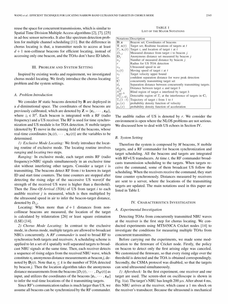
TABLE ILIST OF THE MAJOR NOTATIONS
The audible radius of US is denoted by r. We consider theenvironment is open where the NLOS problems are not serious.We discussed how to deal with US echoes in Section IV.
B. System Setting
Therefore the system is composed by M beacons, N mobiletargets, and a RF commander for beacon synchronization andtarget scheduling. All the beacons and targets are integratedwith RF+US transducers. At time t, the RF commander broad-casts transmission scheduling to the targets. When targets re-ceive the command, some of them broadcast US follow thescheduling. When the receivers receive the command, they starttime counter synchronously. Distances measured by receiversare sent to a server, where the locations of the transmittingtargets are updated. The main notations used in this paper arelisted in Table I.
IV. CHARACTERISTICS INVESTIGATION
A. Experimental Investigation
Detecting TOAs from concurrently transmitted NBU wavesat the receiver is the first step for chorus locating. We con-ducted experiments using MTS450CA Cricket nodes [14] toinvestigate the conditions for measuring multiple TOAs fromconcurrent transmitters.
Before carrying out the experiments, we made some mod-ification to the firmware of Cricket node. Firstly, the policyon beacon to detect only the first arising edge was canceled.We customized the firmware, so that every rising edge over thethreshold is detected and the TOA is obtained correspondingly.Secondly, the CSMA protocol was disabled, so that the targetscan send ultrasound simultaneously.
1) Aftershock: In the first experiment, one receiver and onetarget are used. The screen-shot on oscilloscope is shown inFig. 1(a). The target’s NBU has length 200 μs. After about 4 ms,this NBU arrives at the receiver, which cause a 1 ms shock onthe receiver’s transducer. Because the ultrasound is mechanical

2346 IEEE JOURNAL ON SELECTED AREAS IN COMMUNICATIONS, VOL. 33, NO. 11, NOVEMBER 2015
Fig. 1. Experiments to test how the separation of NBU peaks is affected by the distances between the transmitters. (a) one target, one receiver. (b) two targetshave different distances to the receiver. (c) two targets have the same distance to the receiver.
wave, the shocking on the receiver is much longer than thelength of the wave sent by the target. This phenomenon is calledaftershock. When the sensor in the receiver is experiencingan aftershock, the comparator in the sensor is kept in highstate, which will block the detection of the newly arrived NBUwavefront. From the oscilloscope output, we can also see somesecondary peaks caused by the echoes. These secondary peakscan be filtered out because their powers are lower than thethreshold. After the energy of the aftershock fades below thethreshold, the comparator switches to low state, which is readyfor detecting the next NBU wave.
2) Multiple TOA Detections: Two targets and one receiverare used in the second experiment, in which targets’ distancesto the receiver differs by 0.7 m. When the two targets transmitUS signal simultaneously, the detected waves at the receiver areshown in Fig. 1(b). Two NBU riding edges are detected whichindicate TOAs from two targets. But note that the detectedTOAs are anonymous, i.e., the receiver don’t know the targetID of the TOA.
In the third experiments, the two targets are placed at thesame distance to the receiver. The captured US waves at thereceiver are shown in Fig. 1(c). We can see only one rising edge.This is because the difference of two waves’ arriving times isshorter than the first wave’s aftershock. In this case, only oneTOA can be detected whose source ID cannot be known.
B. Extract the Multiple TOA Detection Condition
The experiments showed that whether two successive NBUwaves arrived at a receiver could be successfully detected wasdetermined by the time separation between the two arrivedUS waves. If the time separation is longer than the lengthof the aftershock generated by the first wave, the rising edgeof the second wave can be detected. Since the length of theaftershock is affected by the received energy of the NBU signaland the character of US sensor, it will be better to chooseultrasound transducer with weak inertia and shorter aftershock.To formulate the impact of the aftershock, let’s denote Lmax bethe longest possible aftershock generated by the first wave atthe receivers. Let vu be the speed of the ultrasound, then
Definition 1 (Confident Separation Distance): We define ω=Lmaxvu as the confident separation distance.
Lmax indicates the time separation for detecting two wavefronts successfully. ω turns this separation requirement to thedistance separation. If two targets’ distances to a receiver(in their sensing range) differ more than ω, the receiver can
Fig. 2. Triangle inequality relationship.
detect two unlabeled TOAs in case the two targets transmitsimultaneously.
From triangle inequality as shown in Fig. 2, if the distancefrom two targets to a receiver differs more than ω, the distancebetween the two targets must be larger than ω. Let’s further takethe audible region of the receiver into consideration. Let audibleradius r be the maximum propagation distance of BNU beforeits strength is lower than the detecting threshold. By combiningthe separation distance with the audible range, we can get thefollowing multiple TOA detection condition:
Theorem 1 (Multiple TOA Detection): We consider twotargets a and b are at location xa and xb respectively, whichsend NBU waves concurrently. One receiver at location zx candetect the TOAs from the two targets if:{
|da,x − db,x| > ω
Da,x � r, Db,x � r(1)
where di,j is the distance between xi and xj; Da,x is the distancefrom target a to beacon x.
For multiple-target transmitting case, we only need to con-sider the targets in the audible region of each receiver. Tocheck whether a receiver can detect TOAs from the concur-rently transmitting targets, we can simply sort their distancesto the receiver in ascending order {d1 ≤ d2 ≤ · · · dn}. If ∀i =1, · · · , n − 1, di+1 − di > ω, then the receiver can successfullydetect the TOAs of signals from all these targets.
C. “Blind Region” Impacted by Concurrent Targets
Let’s consider a more complex problem when there aremultiple receivers want to track multiple transmitters. We firstly

WANG et al.: EFFICIENT TECHNIQUE FOR LOCATING NARROW-BAND ULTRASOUND TARGETS IN CHORUS MODE 2347
Fig. 3. The blind region of a caused by b.
consider in which region can receivers detect TOA from a whenanother target b is transmitting concurrently. We investigate thisproblem in 2-D space, which has the same principle in 3-Dspace.
Definition 2 (Blind Region): Blind region of target a causedby target b is a subregion in the audible region of a, in which thereceivers cannot detect TOA from a when a and b transmit con-currently. The blind region of a caused by b is denoted by SB
a←b.Let (x, y) be an arbitrary coordinate in the 2-D space, rep-
resenting the location of a receiver, for two targets a and bat location (xa, ya) and (xb, yb), the functions |da,x − db,x| =0 |da,x − db,x| = ω partitions the audible region of a in the2-D space into three subregions. The blind region SB
a←b ischaracterized by the mid-perpendicular between (xa, ya) and(xb, yb) and the hyperbola: |da,x − db,x| = ω.
In Fig. 3, the blind region SBa←b is shown in grey color.
Receivers in this region cannot detect TOA from a because theinterference from b. Depending on the distance between a and
b, the area of SBa←b varies from 0 to πr2
2 . Fig. 4 shows how SBa←b
changes with da,b. The area of blind-region can be expressed inclose form as a function of da,b.
SBa←b(da,b) =
⎧⎪⎪⎪⎨⎪⎪⎪⎩
0 da,b > 2r
r2(θ−sin θ cos θ) 2r − ω ≤ da,b ≤ 2r
r2(θ−sin θ cos θ) − Se ω < da,b < 2r − ω
r2(θ−sin θ cos θ) 0 < da,b ≤ ω.
(2)
The detailed expansion of SBa←b(da,b) can be referred in
Appendix A. We should note that the area of SBa←b is a mono-
tone decreasing function of da,b. The smaller is da,b, the largeris the blind region. Now, let’s consider the TOA-detectable re-gion when there are multiple concurrently transmitting targets.
Definition 3 (TOA Detectable Region (TDR)): Let a k tar-gets T1, · · · , Tk transmit concurrently. Let set Ci={T1, · · · ,
Tj, · · · , Tk}(j �= i) be the concurrently transmitting targets ex-cept Ti. Denote the TOA detectable region of target Ti at theinterference of Ci by SD
Ti←Ci. Then SD
Ti←Ci= SA
Ti\ ∪s∈CiS
BTi←s,
which is the audible region of Ti subtract the blind regionscaused by other concurrent transmitting targets.
D. Lower Bound of TOA Detectable Region (TDR)
In d-dimension space, for locating a target, TOA measure-ments from more than d + 1 non-collinear beacons are neededfor trilateration. If Least Square Estimation is used, more num-
ber of TOA are involved in calculation can reduce the locationvariance. Therefore, an intuition for locating target accurately inchorus mode is to make sure the TOA detectable region (TDR)of a target be big enough, so that more non-blind beacons canbe accommodated to contribute enough TOA measurements.
Therefore, in this subsection, we characterize a lower boundof SD
Ti←Ciwhen the pairwise distances among the concur-
rently transmitting targets are larger than a minimum pairwisedistance ds. The minimum pairwise distance exists becausethe fact that in real applications, the concurrently transmit-ting targets are scattered in the monitoring field. We can alsoschedule based on the targets’ locations to make the concurrenttransmitters well serrated (will be introduced soon). Based onit, the lower bound of SD
Ti←Ci, which is a function of k, ds and
r will provide guidelines for target transmission scheduling inthe chorus mode locating.
Theorem 2 (Most Interfering Target Distribution): Whenk − 1 interfering targets with minimum pairwise distance ds arepresenting, the k − 1 targets generate the largest blind region toa when they are located on the circle centered at a, with radiusds, and separated by angle 2π
k−1 , i.e., evenly distributed on thecircle with radius ds around a.
Proof 1: First, since SBa←s is a monotone decreasing
function of the distance between a and s. ∀s = {T1, · · · , Tk, s �=a}, SB
a←s is the largest when da,s is the minimum, i.e., da,s = ds.Secondly, we prove the overlapping area of the blind regionsare largest when other targets are evenly separated on the circlearound Ti with radius ds. We treat the problem as a set coverproblem. The audible region of a can be thought as a wholeset containing infinite points. SB
a←s is a covering subset andthe k − 1 covering subsets are isotropic, i.e., with the same sizeand the same shape. By inclusion-exclusion principle, the unionof the most exclusive subsets will contribute the largest coverto the whole set. The subsets are most exclusive when the k − 1targets are evenly separated on the circle around Ti.
Fig. 5 shows the maximum union area of the blind regions ofa when |T| = 2, 3, 4, 5, 6 respectively. Other targets generatesthe maximum blind region to a when they are symmetricallydistributed on the circle around a with radius ds. The area ofSD
a←Cireaches the lower bound in such case, which affects the
possible number of non-blind beacons in it.More generally, when the number of concurrently transmit-
ting target, i.e., k is unknown and the target distribution isarbitrary, we can also derive a lower bound for SD
a←Cionly if
ds is given.Theorem 3 (General Lower Bound of SD
a←Ci): The lower
bound of SDa←Ci
for given pairwise separation ds is:
SDa←Ci
≥ π
(ds
2
)2
(3)
Proof 2: From (2), the inscribed circle centered at a withradius ds/2 must not be in the blind region generated by anyother target. So the circle area with radius ds/2 must be in theTDR. Its area gives lower bound to SD
a←Cias shown in Fig. 6.
We can see the lower bound is a monotone increasingfunction of ds, which means that the larger is the pair-wise

2348 IEEE JOURNAL ON SELECTED AREAS IN COMMUNICATIONS, VOL. 33, NO. 11, NOVEMBER 2015
Fig. 4. The grey region stands for blind region, where the rest part in audible-circle is audible region. (a) da,b > 2r. (b) 2r − ω ≤ da,b ≤ 2r. (c) ω < da,b <2r − ω. (d) 0 < da,b ≤ ω.
Fig. 5. Blind-region of target a caused by different number of other targets. (a) Blind region by 2 targets. (b) by 3 targets. (c) by 4 targets. (d) by 5 targets.(e) by 6 targets.
Fig. 6. Lower bound of blind-region.
separation among the targets, the larger is the area of TDR fora target.
E. Probability of Having at Least Three Beacons in TDR
Consider in 2D space, TOA measurements from three non-collinear beacons are needed for trilateration. Based on thelower bound of SD
a←Ci, for any given distribution of the beacons,
we can evaluate the probability and the expectation of at leastthree beacons in the TDR region of a target. The probability canguide the transmitter scheduling scheme to choose proper ds forachieving good target tracking performances.
Let’s consider a general case when the receivers are in Pois-
son distribution, i.e. P(nr = k) = λke−λ
k! , where λ is the expectednumber of receivers in a unit area (e.g. 1 m2). By substituting
the lower bound of SDa←T ≥ π
(ds2
)2, the probability of at least
three receivers are in SDa←T can be calculated as:
1 −2∑
i=0
p(nr = i) ≥ 1 − e− λπd2s
2
[1 + λπd2
s
2+ λ2π2d4
s
8
](4)
Theorem 4: When receivers are in Poisson distribution with λ
expected receivers in a unit area, when the pair-wise separationamong targets are larger than ds, the probability of at least
Fig. 7. Probability of three receivers are in TDR.
three receivers are presenting in the TDR of a target is lowerbounded by
1 − e− λπd2s
2
[1 + λπd2
s
2+ λ2π2d4
s
8
]. (5)
Fig. 7 plots the lower bound of P(nr ≥ 3) as a function ofds and λ. We can see that for given λ, the lower bound of atleast three receivers presenting in the TDR of a target increasesexponentially with ds. Note that the figure plots only the lowerbound. Because the real TDR area can be much larger than thelower bound area of TDR, in real case, the probability of threereceivers are in the TDR of a target can be much closer to 1.
The results in Fig. 7 show the strong feasibility of choruslocating. Targets only need to be separated by 2 to 5 meters incase of different beacon deployment densities for obtaining atleast three distance measurements for locating a mobile target.
V. TRANSMISSION SCHEDULING
The characteristics of the TDR area and the requirementof multiple TOA measurements for locating a target inspire alocation-based transmission scheduling scheme. It starts from

WANG et al.: EFFICIENT TECHNIQUE FOR LOCATING NARROW-BAND ULTRASOUND TARGETS IN CHORUS MODE 2349
Fig. 8. An example of LBTA to assign time slots.
the initial state where each target transmits in exclusive timeslot. When the targets’ locations are known, targets are dividedinto several concurrent transmission groups. Targets in the samegroup transmit US concurrently. The schedule is conducted bya controller and is delivered to the targets by a RF messages.
The main idea is to let targets with enough pair-wise separa-tion distances to transmit concurrently. A location based time-slot assignment (LBTA) algorithm was designed. It assignsexclusive time-slots to targets which are close to each other orwith unknown locations, and let targets with known locationtransmit concurrently in a greedy manner.
At first in LBTA, a confident separation distance ds iscalculated by the lower bound of TDR region (5) based onthe given density of the receivers to guarantee the probabilityof P(nr ≥ 3) approaching 1. Then the targets with knownlocations will be separated into a set of ds-separated groups.Each group consists of several ds separated targets. Each groupoccupies an exclusive time slot and targets in the same grouptransmit together. Exclusive slots are assigned to the targetswith unknown locations.
An example of LBTA is shown in Fig. 8, in which, six targetsare presenting. We assume the locations of target {1, . . . , 5} areknown and the locations of targets 6 is still unknown. In thiscase, the targets with known locations are separated into twods-separated groups. Totally three slots are assigned to the sixtargets.
Although finding the minimum number of ds-separatedgroup is NP-hard [3], this problem can be effectively addressedby a greedy approach in practice when the number of targets arelimited. We proposed a greedy DivideClosestTargets algorithmto address it.
Algorithm 1 DivideClosestTargets
Require: {x1, . . . , xN} and ds
Ensure: ds-seperated group partition, G1, . . . ,Gnd
1: nd ← 1, tempg1 ← {x1, . . . , xN}, tempg2 = ∅2: while ∪nd−1
i=1 Gi �= {x1, . . . , xN} do3: while (MinPairWiseDis(tempG1) < ds) do4: [i, j] = select the closest pair in tempg15: tempG1 = tempG1 \ i, tempG2 = tempG2 + i6: end while7: Gnd = tempG1, nd = nd + 18: tempG1 = tempG2, tempG2 = ∅9: end while
DivideClosestTargets always selects the closest pair in thecurrent temp group, and put one of them into a new temp group,until all targets in current temp group have pairwise distancelarger than ds. This temp group will form a ds-separated group.Then the algorithm process the new temp group, until all targetsare assigned into ds-separated groups. The scheduling on onehand improve the location updating rate for individual target,on the other hand helps to provide enough number of TOAsfor locating each target in the chorus mode. When new targetsentered the system, it registers itself to the scheduler by sendingRF signal, so that the scheduler will assign slots to it for get itinitial location and adds it into the later scheduling loops. Whenthe ultrasound from a target has not been received for a longenough time, the scheduler judges the target has left and stopsto assign time slot to it.
Based on the scheduling, beacons detect multiple TOAs fromconcurrently transmitting targets. The next step is how to deter-mine the location of targets based on these anonymous TOAs.
VI. RESOLVING AMBIGUITY
To use these anonymous TOAs for locating mobile targets,we need to label each TOA by possible target IDs, so that todetermine the location of the multiple targets.
What we can rely on is the spatial and temporal consis-tency of each target’s movement, i.e., each target cannot jumpsuddenly. We present a framework to firstly narrow down thepossible IDs of TOAs, and then disambiguate the trajectories ofthe multiple targets by probabilistic particle filter.
A. Algorithm Overview
Let the concurrently transmitting target set by C. The input ofthe problem includes unlabeled TOA measurements at beaconsand the historical locations of the targets in C. Note that thetargets’ historical locations have been available when the targetsturn to the chorus locating mode.
Problem 1 (Chorus Locating Problem): Let’s define a roundas a period in which all targets can finish location updating.Then in round t, the problem inputs include (1) Anonymousdistances measured by the beacons at round t, denoted by[D1(t), · · · , DM(t)]; (2) Coordinates of these beacons, denotedby [z1, · · · , zM], (3) The historical positions of the concurrentlytransmitting targets, denoted by {xi(t − 1), i ∈ C}. The problemoutput is to determine the real-time locations of the targets in Cat a round t.
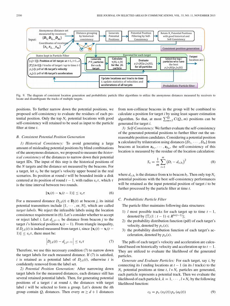
To address this problem, the overview of the proposed tech-niques are shown in Fig. 9, which contain mainly two parts: 1)consistent position generation and 2) probabilistic particle filterfor trajectory disaggregation.
1) Overview of Consistent Position Generation: Every d + 1distances from non-collinear beacons can generate a positioncandidate. Enumerating the combinations of the anonymousdistances will generate a large amount of possible positions.To narrow down the potential positions, we firstly proposed toreject the infeasible distance groups by historical-consistency,i.e., by utilizing the consistency of distance measurements withthe latest location estimations of the targets. After this step,the distance groups are utilized to generate a set of potential
2350 IEEE JOURNAL ON SELECTED AREAS IN COMMUNICATIONS, VOL. 33, NO. 11, NOVEMBER 2015
Fig. 9. The diagram of consistent location generation and probabilistic particle filter algorithms to utilize the anonymous distances measured by receivers tolocate and disambiguate the tracks of multiple targets.
positions. To further narrow down the potential positions, weproposed self-consistency to evaluate the residues of each po-tential position. Only the top Nc potential locations with goodself-consistency will retained to be used as input to the particlefilter at time t.
B. Consistent Potential Position Generation
1) Historical Consistency: To avoid generating a largeamount of misleading potential positions by blind combinationsof the anonymous distances, we proposed to measure the histor-ical consistency of the distances to narrow down their potentialtarget IDs. The input of this step is the historical positions ofthe N targets and the distance set measured by the beacons. Fora target, let ve be the target’s velocity upper bound in the realscenarios. Its position at round t will be bounded inside a diskcentered at its position of round t − 1, with radius veτ , which τ
is the time interval between two rounds.
‖xi(t) − xi(t − 1)‖ ≤ veτ (6)
For a measured distance Dj,k(t) ∈ Dj(t) at beacon j, its initialpotential transmitters include {1, · · · , or, N}, which are calledtarget labels. We reject the infeasible labels using the locationconsistence requirement in (6). Let’s consider whether to acceptor reject label i. Let dj,i(t−1) be distance from beacon j to thetarget i’s historical position xi(t − 1). From triangle inequality,if Dj,k(t) is indeed measured from target i, since ‖xi(t) − xi(t −1)‖ ≤ veτ , there must be:∣∣∣Dj,k(t) − dj,i(t−1)
∣∣∣ ≤ veτ (7)
Therefore, we use this necessary condition (7) to narrow downthe target labels for each measured distance. If (7) is satisfied,i is retained as a potential label of Dj,k(t), otherwise i isconfidently removed from the label set.
2) Potential Position Generation: After narrowing downtarget labels for the measured distances, each distance still hasseveral retained potential labels. Then, for generating potentialpositions of a target i at round t, the distances with targetlabel i will be selected to form a group. Let’s denote the ithgroup contain Qi distances. Then every m ≥ d + 1 distances
from non-collinear beacons in the group will be combined tocalculate a position for target i by using least square estimationalgorithm. So that, at most
∑Qim=3 C(Qi, m) positions can be
generated for target i.3) Self-Consistency: We further evaluate the self-consistency
of the generated potential positions to further filter out the un-reasonable position candidates. Considering a potential positionx calculated by trilateration using distances [D1, · · · , Dm] frombeacons at location zb1, · · · , zbm , the self-consistency of thislocation is measured by the residue of the location calculation:
Sx = 1
m
m∑i=1
(Di − dx,bi
)2 (8)
where dx,bi is the distance from x to beacon bi. Then only top Nc
potential positions with the best self-consistency performanceswill be retained as the input potential position of target i to befurther processed by the particle filter at time t.
C. Probabilistic Particle Filter
The particle filter maintains following data structures:
1) l most possible tracks for each target up to time t − 1,denoted by {Ti(1 : t − 1) ∈ Rl∗(t−1)};
2) the probability distribution function (pdf) of each target’svelocity, denoted by pv(x);
3) the probability distribution function of each target’s ac-celeration, denoted by pa(x).
The pdfs of each target’s velocity and acceleration are calcu-lated based on historically velocity and acceleration up to t − 1.They are utilized to evaluate the likelihood of the generatedparticles.
Generate and Evaluate Particles: For each target, say i, byconnecting its l ending locations at t − 1 (in its l tracks) to theNc potential positions at time t, l ∗ Nc particles are generated,each particle represents a potential track. Then we evaluate thelikelihood of each particle k, k = 1, · · · , l ∗ Nc by the followinglikelihood function:
ck = pv (vk(t)) pa (ak(t)) (9)

WANG et al.: EFFICIENT TECHNIQUE FOR LOCATING NARROW-BAND ULTRASOUND TARGETS IN CHORUS MODE 2351
Fig. 10. Evaluate the cost of each generated particle.
where vk(t) and ak(t) are calculated on the particle k by:
vk(t) = |xk(t) − xk(t − 1)| , ak(t) = vk(t) − vk(t − 1). (10)
The top l particles with best likelihood will be retained for thetarget for the next step, and x(t) in the most possible particlewill be output as the position estimation at time t. The pdfsof velocity and acceleration are updated accordingly. Such aprogress will be applied to all the targets, and the algorithmof the probabilistic particle filter is listed in Algorithm 2.Fig. 10 illustrates the principle of proposed probabilistic par-ticle filter.
Algorithm 2 Probability Particle Filter for a Target i
Require: Ti(1 : t − 1), possible location {x1x2, . . . , xnc}.PDF of velocity pv(·) and PDF of acceleration pa(·).Ensure: Updated Ti(1 : t), pv(·) and pa(·), xi(t).1: {p1, . . . , pl×nc}←Ti(1 : t−1)×{x1, . . . , xnc} // Generate
particles by possible locations of tracks at t − 12: {c1, . . . , cl×nc} ← 03: for i = 1 : l × nc do4: vk(t) = |xk(t) − xk(t − 1)|5: ak(t) = vk(t) − vk(t − 1)
6: ck = pv(vk(t)) · pa(ak(t))7: end for8:{p̂1, . . . , p̂l×nc}←sorting {p1, . . . ,pl×nc} by {c1, . . . ,cl×nc}
in ascending order9:Ti(1 : t) ← {p̂1, . . . , p̂l} // preserve the first l sorted
particle10: pa(·) ← UpdatePDF(pa(·), {v1(t), . . . , vl(t)})11: pv(·) ← UpdatePDF(pv(·), {a1(t), . . . , al(t)})12: xi(t) = p̂1
Complexity of Algorithm 2 can be easily verified.Lemma 1: Complexity of algorithm 2 is O(NNcl log(Ncl))
Proof 3: For each target, the most expensive step is to sortthe l ∗ Nc elements, which takes O(Ncl log(Ncl))), so the overallcomplexity for locating the N targets is O(NNcl log(Ncl))).
The probabilistic particle filter provides good flexibility. 1) Itsupports the trade off between the locating accuracy and the ex-ecuting time by changing the number of the preserved particles.2) The likelihood of each Particle is calculated by consideringboth the velocity and the acceleration, which is online continu-ously updated, so that it can be suitable even when the targetshave variated motion characters.
A potential drawback of this particle filter approach is thata target may be lost when it is too close to other targets.When the location candidates of two targets are almost thesame, all particles may follow one target and none particlefollows the other. But this problem can be prevented in our ap-proach by the location-based transmission scheduling scheme.The location-based transmission scheduling can avoid closetargets transmitting together, which reduces the ambiguity inparticle filter.
VII. EVALUATION
Both simulations and experiments were conducted to eval-uate the performances of multiple target locating in chorusmode. More specifically, the locating accuracy, efficiency ofscheduling and, the robustness of chorus locating against noisewere evaluated and reported in this section. More specifically,aforementioned collision model was implemented in simula-tion part. Simulation was conducted by Matlab 2013. In thesimulation, several independent targets moving in 2D space,several receivers at fixed locations stood for beacons. Distancemeasurements from concurrent transmitting targets to the bea-cons were recorded in the form of matrix [di,j], while di,j
was the range between beacon i to target j. Considering thecharacteristics of the NBU signal, i.e., anonymity, collision,attenuation and NLOS propagation, ToA measurement matrix[di,j] was processed as follows.
1) Anonymity: Each row of [di,j] was sorted in ascendingorder, such that di,j was the jth large range to receiver i.The association between index and identity of target waserased.
2) Collision: di,j was set to invisible if ∃di,k, such that 0 <
di,j − di,k < ω.3) Attenuation: di,j was set to invisible if di,j > R.4) NLOS propagation: A random positive matrix [υi,j]
was added to [di,j], where υ was i.i.d. random vari-able with uniform distribution to simulate the rangingnoise.
The collision distance ω and the length of NLOS noise isimportant in simulation. Primary experiment was performedbefore simulation to learn ω. The value of NLOS noise wasmeasured in our previous work [20], which can be resolved bysensor fusion algorithms [10], [15].
A. Primary Experiment for ω’s Distribution
To measure ω, 4 targets and 1 receiver were used and thelength of ω was measured by Oscilloscope. Oscilloscope wasset to capture the rising-edge and lasting time of the receivedultrasound signal. The width of signal over a threshold wascaptured as ω. In the first experiment, one target was sched-uled to send signal periodically. In the second experiment,four targets were scheduled to work in chorus mode. Thewidth distribution of ω captured by the receiver were shownin Fig. 11.
When one target was transmitting, ω distributed mainlywithin [0, 1]. The distribution is like a normal distribution,

2352 IEEE JOURNAL ON SELECTED AREAS IN COMMUNICATIONS, VOL. 33, NO. 11, NOVEMBER 2015
Fig. 11. Distribution of aftershock. (a) Distribution of aftershock by onetarget. (b) Distribution of aftershock by 4 targets.
Fig. 12. Setting of simulation.
with μ = 0.5 and σ = 1. When 4 targets worked concurrently,omega increased because of the inevitable signal interference.In this case, the major distribution was within [0, 1.5 m]. Weused these parameters in simulation.
B. Simulation
1) Settings of Simulation: Multi-agent simulation was con-ducted in MATLAB. Each target conducted random walk inde-pendently in 2-dimensional space, with parameter settings likehuman being’s. The parameters included velocity, specified bymean value μv = 2 m/s and deviation σv = 1 m/s, the intervalbetween turning, the time between turning, and the turningangle. Receivers were deployed at intersection of grid, whoseunit size was 3 m × 3 m. Simulation proceeded in constantstep, 1 ms. In every step, location of every target was updated.Fig. 12 showed the deployment of receivers and the examplesof the targets’ trajectories. The triangles stood for the startpoints and circle stood for the end points. In simulation, thesetrajectories were used as ground-truth, with which the locatingerror could be calculated.
Fig. 13 shows the ranges obtained in exclusive mode and cho-rus mode in simulation at the receivers part. Upper sub-figureshows the ranges obtained in exclusive mode and the lower sub-figure shows that obtained in chorus mode. The bar clustered ata receiver Ri stands for the range obtained by the receiver i. Wecan see that in chorus mode, fewer ranges were obtained due tothe collision and the identities of ranges were lost, indicated bythe single color of the bars. The codes and simulation settingare hosted in the following public repository for open access.(https://bitbucket.org/thufresh/multipletargetscheduling).
Fig. 13. Range obtained by receivers.
2) Tracking Fidelity: The most significance of chorus locat-ing is that the targets can be located in high refreshing rate,which is useful especially when trajectory of targets containsharp turns. To validate this fact, the same trajectories weretracked in both exclusive and chorus modes. Tracking resultsof two different modes were compared from several aspects.In chorus mode, ω was assigned to 0.5 meter, which is theaveraged value obtained in primary experiment. In both thechorus mode and the exclusive mode, the locating time slot wasset to 100 ms, which was used in Dragon [20] and Cricket [14].
Fig. 14(a)–(c) show the locating results in exclusive andlocating in chorus mode respectively. In general, the ground-truth of each trajectory is a piece-wise linear curve plus slightswings. The tracking results in exclusive mode were smootherthan the ground-truth, which was caused by the low refreshingrate. The slight swings and sharp turns were lost in the exclusivemode. The tracking results obtained in chorus mode were moresharp. The sharp turns could be seen in the tracking results.The side effect is that, some locating errors are presented at thestraight lines. The difference could be seen clearly by zoominginto a specific trajectory, for example, the black one. Let’s focuson two parts in the trajectory, which are denoted by the blueand red circles. In the part denoted by the red circle, sharp turnhappens. Tracking result in chorus mode can follow the ground-truth well due to the higher refreshing rate. In the same area,the exclusive mode fails to follow the sharp turn due to the biginterval between the location update. While in the blue circuitarea, chorus mode has big locating error, which may be causedby the shortage of range because of collision. By comparing thelocating result in chorus mode with the ground-truth point-by-point, the locating error in chorus mode can be counted. Linearinterpolation was performed on the chorus locating result tomake its spatial resolution equal to the ground-truth. Trackingerror in exclusive mode was obtained in the same way. Thecumulated distribution of the locating error of two mode arecontrasted in Fig. 14. Obviously, the tracking accuracy obtainedin chorus mode is slightly better. Not that in the comparison, noranging error is introduced. The robust of chorus locating wastested in the following subjects.
3) Tracking Accuracy Over NLOS Noise and Collision: Inchorus locating, collision may caused by shortage of ranges,which results in location failure. When range measurement isdegenerated by NLOS error, the locating result may get evenworse. How the collision and noise affects the accuracy oflocating is revealed in this subject.

WANG et al.: EFFICIENT TECHNIQUE FOR LOCATING NARROW-BAND ULTRASOUND TARGETS IN CHORUS MODE 2353
Fig. 14. Tracking fidelity contrast between chorus mode and exclusive mode. (a) Ground-truth. (b) In exclusive mode. (c) In chorus mode. (d) Zoom-in for detail.(e) CDF.
Fig. 15. Robustness and efficiency of chorus locating. (a) CDF vs ω. (b) CDF vs. noise. (c) Locating accuracy over both Noise and ω. (d) Timeslot reuse changeswith ω.
The setting of simulation was the same as in the previoussubject. To reveal the effect of collision, the length of ω waschanged from 0.5 m to 5 m, The maximum NLOS noise wasalso increased from 0 to 50cm. For each combination of thesetwo parameters, CDF of locating error was calculated.
CDF of locating error obtained with different ω is shown inFig. 15(a). The locating error obtained in the exclusive modeis denoted by the dashed line, while CDF with chorus modeis denoted by the solid line. The black broken line illustratedthe position of 90% ratio. The 90% line is intersected by everycurve, while the x-coordinate of the intersection spot indicatesthe locating accuracy. In general, the locating accuracy de-creased with ω from centimeter level to about 1 m. In particular,when ω is less than 0.2 meter, the locating accuracy is betterthan the exclusive mode. Referring to Fig. 11(b), the majorityof ω is smaller than 1 meters in practice, such that we can expectthe locating accuracy in less than 1 meter.
When NLOS error in introduced, locating accuracy is de-generated. In practical system, such as Dragon and Cricket,NLOS is introduced by the reflection propagation on the wall,ceiling and facilities nearby, therefore the NLOS error variedin different environment. Experiment in Dragon shows that theranging error is distributed over [0, 0.5 m]. In our simulation,the same range error distribution was applied to the rangingmeasurement. Fig. 15(b) shows that the locating error wasnot sensitive to the change of the NLOS noise. The reasonis because of the Least Square Estimation, which reduce theNLOS effect in certain degree.
The location accuracy distribution over both ω and the NLOSnoise is illustrated in Fig. 15(c). Each vertex (ω,N , z) on thesurface means that the locating accuracy is z under collisionlength ω and noise length N . It is noted that, when ω = 0, weuse exclusive locating other than chorus locating. An remarkof Fig. 15(c) is that the locating accuracy is more sensitive toω other than noise. This remark indicates the importance of
LBTA scheduling protocol, which can reduce the probabilitythat collision happens.
4) Performance of LBTA: Chorus locating allows multipletargets to be located in one time-slot. The number of targetslocated in one time-slot, denoted by nu was referred as time-slot reuse ratio. In exclusive mode, nu = 1 is constant. In choruslocating, nu is a variable, which is determined by the schedulingalgorithm. Experiments in simulation showed how nu changedin the locating process and how nu was affected by ω. When50 targets were deployed in 10 m × 10 m 2D space, choruslocating was performed in every 100ms interval. nu for the first200 locating round was recorded.
As shown in Fig. 15(d), for every ω, nu equals to 1 ini-tially and increased gradually with the locating process. Thisis because the LBTA initialized each un-located target withan exclusive time-slot. As the locating process continued, thenumber of un-located target reduced. As LBTA increased thetransmitting concurrency, the time-slot reuse ratio increased.But if ω increased, less concurrent transmitters can be sched-uled. We can see the time-slot reuse ratio decreased with ω.
C. Testbed Experiment
We developed testbed systems to verify the proposed chorusmode ranging and chorus mode locating methodologies. Ex-periments were conducted in two systems: one is composed bywireless targets and wireless receivers, called wireless system;another is our previously developed Dragon system [20], inwhich the receivers are connected by cables.
The Wireless System: In the wireless system, targets andreceivers were implemented by the Cricket [14] node. Thedifference from the Cricket system is that the targets in oursystem don’t broadcast RF signal for time synchronization. In-stead, an external wireless commander works as synchronizingcommander to broadcast RF to all receivers and targets. Each
2354 IEEE JOURNAL ON SELECTED AREAS IN COMMUNICATIONS, VOL. 33, NO. 11, NOVEMBER 2015
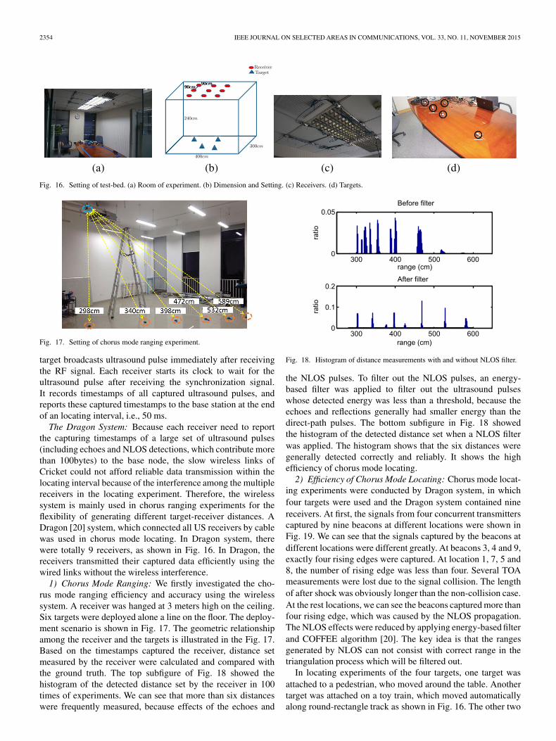
Fig. 16. Setting of test-bed. (a) Room of experiment. (b) Dimension and Setting. (c) Receivers. (d) Targets.
Fig. 17. Setting of chorus mode ranging experiment.
target broadcasts ultrasound pulse immediately after receivingthe RF signal. Each receiver starts its clock to wait for theultrasound pulse after receiving the synchronization signal.It records timestamps of all captured ultrasound pulses, andreports these captured timestamps to the base station at the endof an locating interval, i.e., 50 ms.
The Dragon System: Because each receiver need to reportthe capturing timestamps of a large set of ultrasound pulses(including echoes and NLOS detections, which contribute morethan 100bytes) to the base node, the slow wireless links ofCricket could not afford reliable data transmission within thelocating interval because of the interference among the multiplereceivers in the locating experiment. Therefore, the wirelesssystem is mainly used in chorus ranging experiments for theflexibility of generating different target-receiver distances. ADragon [20] system, which connected all US receivers by cablewas used in chorus mode locating. In Dragon system, therewere totally 9 receivers, as shown in Fig. 16. In Dragon, thereceivers transmitted their captured data efficiently using thewired links without the wireless interference.
1) Chorus Mode Ranging: We firstly investigated the cho-rus mode ranging efficiency and accuracy using the wirelesssystem. A receiver was hanged at 3 meters high on the ceiling.Six targets were deployed alone a line on the floor. The deploy-ment scenario is shown in Fig. 17. The geometric relationshipamong the receiver and the targets is illustrated in the Fig. 17.Based on the timestamps captured the receiver, distance setmeasured by the receiver were calculated and compared withthe ground truth. The top subfigure of Fig. 18 showed thehistogram of the detected distance set by the receiver in 100times of experiments. We can see that more than six distanceswere frequently measured, because effects of the echoes and
Fig. 18. Histogram of distance measurements with and without NLOS filter.
the NLOS pulses. To filter out the NLOS pulses, an energy-based filter was applied to filter out the ultrasound pulseswhose detected energy was less than a threshold, because theechoes and reflections generally had smaller energy than thedirect-path pulses. The bottom subfigure in Fig. 18 showedthe histogram of the detected distance set when a NLOS filterwas applied. The histogram shows that the six distances weregenerally detected correctly and reliably. It shows the highefficiency of chorus mode locating.
2) Efficiency of Chorus Mode Locating: Chorus mode locat-ing experiments were conducted by Dragon system, in whichfour targets were used and the Dragon system contained ninereceivers. At first, the signals from four concurrent transmitterscaptured by nine beacons at different locations were shown inFig. 19. We can see that the signals captured by the beacons atdifferent locations were different greatly. At beacons 3, 4 and 9,exactly four rising edges were captured. At location 1, 7, 5 and8, the number of rising edge was less than four. Several TOAmeasurements were lost due to the signal collision. The lengthof after shock was obviously longer than the non-collision case.At the rest locations, we can see the beacons captured more thanfour rising edge, which was caused by the NLOS propagation.The NLOS effects were reduced by applying energy-based filterand COFFEE algorithm [20]. The key idea is that the rangesgenerated by NLOS can not consist with correct range in thetriangulation process which will be filtered out.
In locating experiments of the four targets, one target wasattached to a pedestrian, who moved around the table. Anothertarget was attached on a toy train, which moved automaticallyalong round-rectangle track as shown in Fig. 16. The other two

WANG et al.: EFFICIENT TECHNIQUE FOR LOCATING NARROW-BAND ULTRASOUND TARGETS IN CHORUS MODE 2355
Fig. 19. Signal captured by 9 receiver.
Fig. 20. Evaluating chorus locating in testbed. (a) Locating 4 targets in chorus mode. (b) Locating 4 targets in exclusive mode. (c) Contrast on timeslot reuse.(d) Contrast on locating accuracy.
targets were placed on table, which were static. The locationtracking results for the four targets in chorus and exclusivemodes were shown in Fig. 20. The traces of four targets wereillustrated by dot-lines of different colors. Each dot stands foran obtained location. The track of the toy train was drawn in thepicture as the ground truth.
According to Fig. 20, the locations obtained by chorus modelocating is much denser than that obtained in exclusive mode.More specifically, we evaluated the time slot reuse ratio. Theresults were compared in Fig. 20(c). In exclusive mode, thetime-slot reuse ratio is always 1. But in chorus mode, the time-slot reuse is 4 in most locating round.
3) Tracking Accuracy: To evaluate the tracking accuracy, thelocating results were compared with the ground-truth. Sincethe ground truth of the pedestrian is hard to obtain, we onlyevaluated the locating error for tracking static targets and thetoy train. In Fig. 20, we can see that the locating results matchedthe ground truth well in both modes. The cumulated distri-bution function of locating error was illustrated in Fig. 20(d).It showed that the tracking accuracy obtained by chorus locat-ing was as good as that obtained in exclusive mode locating. Ingeneral, the testbed experiments verified the fact, that locatingin chorus could provide promising accuracy and much higher
location updating rate than the traditional exclusive mode TOA-based locating.
VIII. CONCLUSION
In this paper, we have investigated how to locate multiplenarrowband ultrasound targets in chorus mode. It is to allowthe targets broadcast ultrasound concurrently to improve theposition updating rate, while disambiguating their locations byalgorithms at the receiver end. We investigated the geometricconditions among the targets for confidently separating theNBU waves at the receivers, and the geometrical conditions forobtaining at least d + 1 distances for each concurrent target.To deal with the anonymous distance measurements, consistentposition generation and probabilistic particle filter algorithmswere presented to label potential sources for anonymous dis-tances and to disambiguate the trajectories of the multipleconcurrent targets. To avoid conflicts of the close by targetsand for reliable initialization, a location based concurrent trans-mission scheduling algorithm was developed. Simulations andexperiments showed the feasibility and efficiency of chorusmode locating. Further work may includes more flexible wave-front detection technique to further shorten the aftershock; anddetection methods to be more robust to echoes and noises.

2356 IEEE JOURNAL ON SELECTED AREAS IN COMMUNICATIONS, VOL. 33, NO. 11, NOVEMBER 2015
APPENDIX
A. Expression of Equation (2)
where
θ = arccosda,b
2r(11)
and
Se =yβ∫
0
(2√
r2 − y2 − ωvu
√1 + y2
d2a,b − 1
4ω2v2u
)dy (12)
where
yβ = bh
ch
√r2 − b2
h − 2ahr (13)
refers to the y coordination of intersection point of hyperbolaand circle.
ah = vuω
2, bh = da,b
2, ch =
√a2
h + b2h (14)
REFERENCES
[1] M. Alloulah and M. Hazas, “An efficient CDMA core for indoor acousticposition sensing,” in Proc. IPIN, 2010, pp. 1–5.
[2] W. Choi, A. Forenza, J. Andrews, and R. Heath, “Opportunistic space-division multiple access with beam selection,” IEEE Trans. Commun.,vol. 55, no. 12, pp. 2371–2380, Dec. 2007.
[3] A. V. Fishkin, “Disk graphs: A short survey,” in Approximation andOnline Algorithms, Berlin, Germany: Springer-Verlag, Jan. 2004, 1–5.
[4] J. Gonzalez Hernandez and C. Bleakley, “Accuracy of spread spectrumtechniques for ultrasonic indoor location,” in Proc. 15th Int. Conf. Digit.Signal Process., Jul. 2007, pp. 284–287.
[5] J. Gonzalez Hernandez and C. Bleakley, “High-precision robust broad-band ultrasonic location and orientation estimation,” IEEE J. Sel. TopicsSignal Process., vol. 3, no. 5, pp. 832–844, Oct. 2009.
[6] J. Gonzalez Hernandez and C. Bleakley, “Low-cost, wideband ultrasonictransmitter and receiver for array signal processing applications,” IEEESensors J., vol. 11, no. 5, pp. 1284–1292, May 2011.
[7] A. Gore, A. Karandikar, and S. Jagabathula, “On high spatial reuselink scheduling in STDMA wireless ad hoc networks,” in Proc. IEEEGLOBECOM, Nov. 2007, pp. 736–741.
[8] M. Hazas and A. Hopper, “Broadband ultrasonic location systems forimproved indoor positioning,” IEEE Trans. Mobile Comput., vol. 55,no. 5, pp. 536–547, May 2006.
[9] M. Hazas and A. Ward, “A novel broadband ultrasonic location sys-tem,” in UbiComp 2002: Ubiquitous Computing, G. Borriello andL. E. Holmquist, Eds., vol. 2498, Lecture Notes in Computer Science,Berlin, Germany: Springer-Verlag, Jan. 2002. 264–280.
[10] S. Iyengar and R. R. Brooks, Distributed Sensor Networks, 2nd ed. ser.Image and Sensor Signal Processing Series, London, U.K., Chapman &Hall, 2012.
[11] L. Lu, H.-C. Wu, and S. S. Iyengar, “A novel robust detection algorithmfor spectrum sensing,” IEEE J. Sel. Areas Commun., vol. 29, no. 2,pp. 305–315, Feb. 2011.
[12] M. Minami et al., “DOLPHIN: A practical approach for implementing afully distributed indoor ultrasonic positioning system,” in UbiComp 2004:Ubiquitous Computing, vol. 3205, N. Davies, E. D. Mynatt, and I. Siio,Eds., Lecture Notes in Computer Science, Berlin, Germany: Springer-Verlag, Jan. 2004, pp. 347–365.
[13] A. Nishitani, Y. Nishida, T. Hori, and H. Mizoguchi, “Portable ultrasonic3d tag system based on a quick calibration method,” in Proc. IEEE Int.Conf. Syst., Man Cybern., Oct. 2004, vol. 2, pp. 1561–1568.
[14] N. B. Priyantha, A. Chakraborty, and H. Balakrishnan, “The Cricketlocation-support system,” in Proc. 6th Annu. Int. Conf. MobiCom Netw.,Aug. 2000, pp. 32–43.
[15] R. R. Brooks and S. S. Iyengar, Multi Sensor Fusion—Theory andPractice. Upper Saddle River, NJ, USA: Prentice-Hall, 1998.
[16] M. M. Saad, C. J. Bleakley, and S. Dobson, “Robust high-accuracy ultra-sonic range measurement system,” IEEE Trans. Instrum. Meas., vol. 60,no. 10, pp. 3334–3341, Oct. 2011.
[17] H. Schweinzer and G. Kaniak, “Ultrasonic device localization and itspotential for wireless sensor network security,” Control Eng. Pract.,vol. 18, no. 8, pp. 852–862, Aug. 2010.
[18] L. Song and Y. Wang, “Locating multiple ultrasound targets in chorus,” inProc. IEEE Int. Conf. SECON, Singapore, Jun. 2014, pp. 99–107.
[19] J. Villadangos et al., “Improvement of ultrasonic beacon-based local posi-tion system using multi-access techniques,” in Proc. IEEE Int. WorkshopIntell. Signal Process., Sep. 2005, pp. 352–357.
[20] Y. Wang and L. Song, “An algorithmic and systematic approach forimproving robustness of TOA-based localization,” in Proc. IEEE 10th Int.Conf. HPCC-EUC, 2013, pp. 2066–2073.
[21] Y. Wang, J. Zhao, and T. Fukushima, “LOCK: A highly accurate, easy-to-use location-based access control system,” in Location and ContextAwareness, vol. 5561, Lecture Notes in Computer Science, Berlin,Germany: Springer-Verlag, 2009, pp. 254–270.
[22] A. Ward, A. Jones, and A. Hopper, “A new location technique for theactive office,” IEEE Pers. Commun., vol. 4, no. 5, pp. 42–47, Oct. 1997.
[23] O. Woodman and R. Harle, “Concurrent scheduling in the active batlocation system,” in Proc. 8th IEEE Int. Conf. PERCOM Workshops,Mar. 2010, pp. 431–437.
[24] U. Yayan, H. Yucel, and A. Yazc, “A low cost ultrasonic based positioningsystem for the indoor navigation of mobile robots,” J. Intell. Robot. Syst.,vol. 78, no. 3/4, pp. 541–552, Jun. 2015.
[25] H. Yin and H. Liu, “Performance of space-division multiple-access(SDMA) with scheduling,” IEEE Trans. Wireless Commun., vol. 1,no. 4, pp. 611–618, Oct. 2002.
[26] J. Zhao and Y. Wang, “Autonomous ultrasonic indoor tracking system,”in Proc. ISPA, 2008, pp. 532–539.
[27] J. Zhao and Y. Wang, “Pospush: A highly accurate location-based infor-mation delivery system,” in Proc. UBICOMM, 2009, pp. 52–58.
Yongcai Wang (M’11) received the B.Sc. and Ph.D.degrees from Tsinghua University, Beijing, China, in2001 and 2006, respectively. From 2007 to 2009, hewas an Associate Researcher with NEC Labs China.From 2009 to 2011, he was a Postdoctoral Fellowwith the Institute for Interdisciplinary InformationSciences, Tsinghua University, where he has beenan Assistant Researcher since 2011. From February2014 to August 2014, he was a Visiting Scholarwith Cornell University. His major research interestslie in the broad area of sensor networks, network
measurement, and wireless locating algorithms and systems. He was a recipientof the best paper awards at Ubicomm2009 and CWSN2011.
Lei Song (S’12–M’14) received the B.Sc. degreefrom Tsinghua University, Beijing, China, in 2007and the M.S. degree from the Institute of ComputingTechnology Chinese Academy of Sciences, Beijing,in 2010. He is currently working toward the Ph.D.degree in the Institute for Interdisciplinary Infor-mation Sciences, Tsinghua University. His researchinterests mainly include wireless sensor network andindoor locating and system.
S. S. Iyengar (F’95) is currently the Ryder Professorof Computer Science and the Director of the Schoolof Computing and Information Sciences at FloridaInternational University, Miami, FL, USA. He hasauthored or coauthored over 400 research papersand eight books and has edited 12 books. He hasbeen involved with research in high-performancealgorithms, data structures, sensor fusion, data min-ing, and intelligent systems. He is a member of theEuropean Academy of Sciences and the Institute ofElectrical and Electronics Engineers (IEEE) Golden
Core and a Fellow of the IEEE, the Association of Computing Machinery, theAmerican Association for the Advancement of Science, and the Society forDesign and Process Science. He was a recipient the Distinguished AlumnusAward of the Indian Institute of Science and the IEEE Computer Society’sTechnical Achievement Award in 1998.