an enpro industries company - aucrom · dcnt 5 micron, 5 ppm csnt, cpnt, cxnt series ... • all...
TRANSCRIPT

QUINCY AIR SYSTEMS
FILTERS
COALESCERS
ABSORBERS
ELEMENTS
an EnPro Industries company

COMPRESSED AIR F I LTERS
STANDARD FILTERS
Particulate — Coalescer — Absorber
Our Standard Filtration lineup consists of thethree most common types of filters used in com-pressed air systems.
THE QUINCY DCN SERIES
Particulate/Coarse Coalescer is designed toremove solids, burnt oil and bulk liquids.
THE CSN, CPN, CXN SERIES
Coalescers remove various levels of liquidaerosols and mist.
THE ACN SERIES
Activated Carbon Absorbers remove vaporsand odors.
• 10 scfm to 16,500 scfm
• 230 psig max. working pressurefor threaded filters
• 150 psig max. working pressurefor flanged filters
• Aluminum housing (1⁄2" to 3" NPT)
• Steel housing (3" to 12" FLG)
MOISTURE SEPARATORS
• 20 to 1500 scfm, 230 psig
• Aluminum housing (1⁄4" to 3" NPT)
OVER & UNDER
COALESCER/ABSORBER
COMBINATION• 10 to 50 scfm/230 psig
• Two-in-one design
PORTABLE AIR SYSTEMS
FOR PAINT OR SANDBLAST
APPLICATIONS(Will not remove certain types of gases, including CO or CO2 )
• 15 cfm two-port manifold
• 30 scfm, four-port manifold
• 230 psig max. working pressure
• Floor stand or wallmounting brackets
• Air pressure regulator
• Air pressure gauge
• Available air heater
HIGH-TEMPERATUREDUST FILTER• +450°F/150 psig• 15 to 1600 scfm
Quincy Filters protect pneumatic equipment and processes from the harmful effects ofcontaminated compressed air by removing dirty water, burnt oil and solid pollutants beforethey can do any damage. Clean compressed air will result in improved production and reducedoperating costs. World class, state-of-the-art material and design make Quincy Compressed AirFilters the standard to which all others must be compared.
QuincyCompressor.com | Made in the U.S.A. | The Science of Compressed Air2

an EnPro Industries company
ELEMENT CONSTRUCTION
Push-to-Fit Design — Aluminum Filters• Easy element replacement
• Fit integrity eliminates leaks,saving energy
Stainless Steel Support Core• Provides strength
• Eliminates corrosion
• Protects element from burstingunder high differential pressure
1st Stage Pre-Filtration Support Layer• Captures larger contaminants
• Protects 2nd Stage filtration media
• Extends service life
Multiwrap 2nd Stage• High void volume minimizespressure drop, saving energy
• Increased surface area ensuresmaximum contaminant retention
• Extended life construction
• Deep bed provides optimumcoalescing efficiency
• Selected media combinationsprovide precise filtration solutions
3rd Stage Interceptor Layer• Provides additional strength
• Optimizes interception process
4th Stage Outer Stainless Steel Support• Ensures total element integrity
Inside to Out Flow• Prolongs element life andimproves drain performance
Polyester Needle Felt Drainage Layer• Optimum oil removal
• High temperature tolerance
• Maximum durability
• Will not disintegrate
• Suitable for use with mineraland synthetic oils
• Tolerant in aggressive environments
Glass-Filled Nylon End Caps• Color-coded for simple elementgrade identification
• Easy element replacement
• Will not corrode
Quincy’s Layered Multiwrap design employs a specially blended borosilicate glassmicrofiber media to produce strong, durable and efficient filter elements. The filtrationmedia combines high flow rates and high dirt-holding capacities without compromisingelement service life. Easy to identify and easy to install, these highly advanced productsoffer the best performance available
ELEMENTS
3

COMPRESSED AIR F I LTERS
STANDARD LINE — PARTICULATE – COALESCER – ABSORBER
Quincy’s Standard Filtration lineup consists of the three most common types of filtersused in compressed air systems. Aluminum housings with threaded NPT connectionsare used for flows up to 1530 cfm and steel housings with flanged connections are usedfor flows up to 16,500 cfm.
• Push-to-fit design used on threaded filters for easyfilter element replacement
• Multiwrap element construction ensures optimumperformance
• Modular design saves energy and allows for easyinstallation of multiple threaded filters
• Aluminum housings feature electrophoretic coatingto prevent corrosion
• 10-year housing guarantee on aluminum housings
• Standard pressure differential indicator onaluminum housings
• Standard automatic condensate drain onaluminum housings
STEEL HOUSINGS,
FLANGED CONNECTIONS 1500 TO 16,000 CFM
SERIES DCNF, CSNF, CPNF, CXNF AND ACNF
DDCCNNTT SSEERRIIEESS
• Designed to remove high concentrations of solids,burnt oil and bulk liquids
DCNT 5 micron, 5 ppm
CCSSNNTT,, CCPPNNTT,, CCXXNNTT SSEERRIIEESS
• Designed to coalesce variouslevels of liquid aerosols. The1 micron CSN is also an idealafterfilter for desiccant dryers.
CSNT 1 micron, 0.1 ppm
CPNT .01 micron, .01 ppm
CXNT .01 micron, .001 ppm
AACCNNTT SSEERRIIEESS
• Activated Carbon Absorberdesigned to remove vaporsand odors. Installed imme-diately downstream ofeither a CPNT or a CXNT coalescer, it will reduce oil carryover to .003 ppm.
• Same filtration grade as aluminum filters
• Identified with an “F” suffix
• U stamped for the USA and CRN approved for Canada
• Housings are freestanding and top loading for easy element replacement
• All grades of filter element end caps are molded, providing strength, durability and long life
ALUMINUM HOUSINGS,
THREADED CONNECTIONS 10 TO 1530 CFM
QuincyCompressor.com | Made in the U.S.A. | The Science of Compressed Air4

an EnPro Industries company
Grade 10 1⁄4 10 17 Grade E 10 1 3 11⁄2 8 3 1.43 0.65 72 35 210 75Grade 20 1⁄4 20 33 Grade E 20 1 3 11⁄2 8 3 1.43 0.65 72 35 210 75Grade 30 3⁄8 30 50 Grade E 30 1 3 11⁄2 8 3 1.43 0.65 72 35 210 75Grade 60 1⁄2 60 100 Grade E 60 1 31⁄2 11⁄4 13 4 2.87 1.30 88 32 315 100Grade 125 3⁄4 125 208 Grade E 125 1 5 11⁄2 15 4 5.95 2.70 125 39 365 100Grade 150 1 150 250 Grade E 150 1 5 11⁄2 15 4 5.95 2.70 125 39 365 100Grade 200 1 200 333 Grade E 200 1 5 11⁄2 21 6 7.72 3.50 125 39 515 150Grade 300 11⁄4 300 500 Grade E 300 1 5 11⁄2 21 6 7.72 3.50 125 39 515 150Grade 425 11⁄2 425 708 Grade E 425 1 51⁄2 2 22 6 9.70 4.40 135 50 545 150Grade 500 2 500 833 Grade E 500 1 51⁄2 2 22 6 9.70 4.40 135 50 545 150Grade 650 2 650 1083 Grade E 650 1 51⁄2 2 30 6 11.00 5.00 135 50 745 150Grade 800 21⁄2 800 1333 Grade E 800 1 8 23⁄4 32 8 25.40 11.50 200 68 805 200Grade 1000 3 1000 1667 Grade E 1000 1 8 23⁄4 32 8 25.40 11.50 200 68 805 200Grade 1300 3 1300 2167 Grade E 1300 1 8 23⁄4 37 8 34.20 15.50 200 68 925 200Grade 1525 3 1525 2542 Grade E 1525 1 9 21⁄2 42 12 41.90 19.00 230 65 1050 300
STANDARD LINE — SPECIFICATIONS & ENGINEERING DATA
MetricElement Number Dimensions Dimensions
Filter Model Pipe Size Flow Rate Model of A B C D Weight A B C D(Grade) NPT scfm Nm3/hr (Grade) Elements In. In. In. In. lb. kg. mm mm mm mm
Complete Filter Assemblies
Grade 1503 3 1500 2550 Grade 1500 1 58 15 48 10 165 74 1472 381 1219 254Grade 1504 4 1500 2550 Grade 1500 1 58 171⁄8 48 61⁄2 175 80 1473 435 1219 165Grade 2004 4 2000 3400 Grade 2000 1 58 213⁄8 481⁄4 13 320 145 1473 543 1226 330Grade 2006 6 2000 3400 Grade 2000 1 591⁄4 251⁄2 48 71⁄2 360 163 1505 648 1219 191Grade 3004 4 3000 5100 Grade 3000 1 72 213⁄8 621⁄4 13 385 175 1829 543 1581 330Grade 3006 6 3000 5100 Grade 3000 1 751⁄4 25.5 64 71⁄2 420 191 1911 648 1626 191Grade 4506 6 4500 7650 Grade 1500 3 831⁄2 251⁄4 681⁄2 231⁄2 580 263 2121 641 1740 597Grade 6008 8 6000 10200 Grade 1500 4 863⁄4 25 68 23 650 295 2203 635 1727 584Grade 10510 10 10500 17850 Grade 1500 7 100 31 80 30 800 363 2540 787 2032 762Grade 16512 12 16500 28050 Grade 1500 11 1133⁄4 441⁄2 87 16 1000 454 2889 1130 2210 406
MetricElement Number Dimensions Dimensions
Filter Model Pipe Size Flow Rate Model of A B C D Weight A B C D(Grade) Flg. scfm Nm3/hr (Grade) Elements In. In. In. In. lb. kg. mm mm mm mm
DCNE 3 4 5 5.0 5.0 248 120 1 40 1 75 6 400 232 16 GreenCSNE 2 2 1 0.1 0.1 248 120 1 75 2 150 6 400 232 16 RedCPNE 1 1 0.01 0.01 0.01 248 120 2 100 4 300 6 400 232 16 BlueCXNE 1 1 0.01 0.001 0.001 248 120 2 140 5 350 6 400 232 16 BlackACNE 1 1 0.01 0.003 0.003 77 25 1 75 — — Min.every 6 months 232 16 Black
Max. Pressure Loss Max. ElementMax. Particle Oil Carryover Max. Change Working End Cap
Filter Max. Particle Size Oil Content Class Removal at 68˚F at 20˚C Temperature Clean & Dry Wet Element Pressure ColorElement to ISO 8573-1:2001 to ISO 8573-1:2001 in Microns ppm mg/m3 ˚F ˚C psi mbar psi mbar psi mbar psig barg Code
Specs
Steel Housings — Flanged
Operating psig 4 9 15 29 44 58 72 87 100 115 130 145 160 174 189 203 218 232Pressure barg 0.3 0.6 1 2 3 4 5 6 7 8 9 10 11 12 13 14 15 16Correction Factor 0.21 0.29 0.38 0.53 0.65 0.76 0.84 0.92 1 1.07 1.13 1.19 1.25 1.31 1.36 1.41 1.46 1.51
For maximum flow rate, multiply model flow rate shown in the above table by the correction factor corresponding to the working pressure.
Correction Factor
Model Grades 10, 20 & 30 Model Grades 60–1525
Model Grades 1503, 1504 & 2004
Model Grades 2006–16512
A
C
D
A
C
B
B
D
5
COMPRESSED A IR F I LTERS
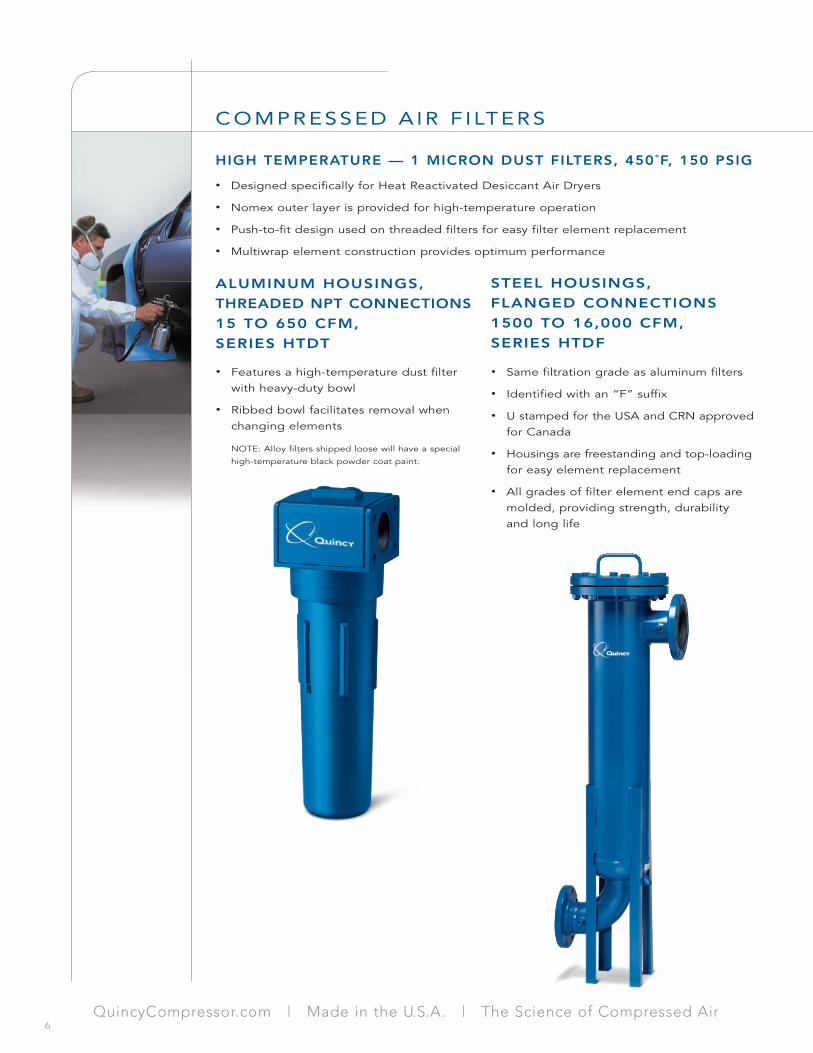
HIGH TEMPERATURE — 1 MICRON DUST FILTERS, 450˚F, 150 PSIG
• Features a high-temperature dust filter with heavy-duty bowl
• Ribbed bowl facilitates removal when changing elements
NOTE: Alloy filters shipped loose will have a special
high-temperature black powder coat paint.
• Designed specifically for Heat Reactivated Desiccant Air Dryers
• Nomex outer layer is provided for high-temperature operation
• Push-to-fit design used on threaded filters for easy filter element replacement
• Multiwrap element construction provides optimum performance
ALUMINUM HOUSINGS,
THREADED NPT CONNECTIONS
15 TO 650 CFM,
SERIES HTDT
• Same filtration grade as aluminum filters
• Identified with an “F” suffix
• U stamped for the USA and CRN approved for Canada
• Housings are freestanding and top-loading for easy element replacement
• All grades of filter element end caps are molded, providing strength, durability and long life
STEEL HOUSINGS,
FLANGED CONNECTIONS
1500 TO 16,000 CFM,
SERIES HTDF
QuincyCompressor.com | Made in the U.S.A. | The Science of Compressed Air6

an EnPro Industries company
HTDT 15 1⁄4 15 25 HTDE 15 1 21⁄2 1⁄2 6 2 0.5 0.25 63 15 150 50HTDT 30 3⁄8 30 50 HTDE 30 1 21⁄2 1⁄2 71⁄2 2 0.6 0.27 63 15 190 50HTDT 65 1⁄2 65 108 HTDE 65 1 41⁄2 11⁄2 12 6 5.7 2.60 114 38 305 150HTDT 75 3⁄4 75 125 HTDE 75 1 41⁄2 11⁄2 12 6 5.7 2.60 114 38 305 150HTDT 150 1 150 250 HTDE 150 1 41⁄2 11⁄2 151⁄2 6 7.3 3.30 114 38 395 150HTDT 300 11⁄2 300 500 HTDE 300 1 53⁄4 2 21 7 16.5 7.50 146 50 435 170HTDT 450 2 450 750 HTDE 450 1 53⁄4 2 21 7 16.5 7.50 146 50 435 170HTDT 650 2 650 1084 HTDE 650 1 53⁄4 2 25 7 22.0 10.00 146 50 635 170
HIGH TEMPERATURE — SPECIFICATIONS & ENGINEERING DATA
MetricElement Number Dimensions Dimensions
Filter Pipe Size Flow Rate Model of A B C D Weight A B C DModel NPT scfm Nm3/hr (Grade) Elements In. In. In. In. lb. kg. mm mm mm mm
Dust Filters — Threaded
HTDF 1503 3 1500 2550 HTDE 1500 1 58 15 48 10 165 74 1473 381 1219 254HTDF 1504 4 1500 2550 HTDE 1500 1 58 171⁄8 48 61⁄2 175 80 1473 435 1219 165HTDF 2004 4 2000 3400 HTDE 2000 1 58 213⁄8 481⁄4 13 320 145 1473 543 1226 330HTDF 2006 6 2000 3400 HTDE 2000 1 591⁄4 25.5 48 71⁄2 360 163 1505 648 1219 191HTDF 3004 4 3000 5100 HTDE 3000 1 72 213⁄8 621⁄4 13 385 175 1829 543 1581 330HTDF 3006 6 3000 5100 HTDE 3000 1 751⁄4 251⁄2 64 71⁄2 420 191 1911 648 1626 191HTDF 4506 6 4500 7650 HTDE 1500 3 831⁄2 251⁄4 681⁄2 231⁄2 580 263 2121 641 1740 597HTDF 6008 8 6000 10200 HTDE 1500 4 863⁄4 25 68 23 650 295 2203 635 1727 584HTDF 10510 10 10500 17850 HTDE 1500 7 100 31 80 30 800 363 2540 787 2032 762HTDF 16512 12 16500 28050 HTDE 1500 11 1133⁄4 441⁄2 87 16 1000 454 2889 1130 2210 406
MetricElement Number Dimensions Dimensions
Filter Pipe Size Flow Rate Model of A B C D Weight A B C DModel Flg. scfm Nm3/hr (Grade) Elements In. In. In. In. lb. kg. mm mm mm mm
Dust Filters — Flanged
High-temperature dust filter element gradeHTDE 1 2 2 450 250 1.1 75 NA NA 6 400 150 10 Brick Red
Max. Pressure Loss Max. ElementParticle Oil Carryover Max. Change Working End Cap
Filter Removal at 68˚F at 20˚C Temperature Clean & Dry Wet Element Pressure ColorElement in Microns ppm mg/m3 ˚F ˚C psi mbar psi mbar psi mbar psig barg Code
Specs
Models HTDT 15 & 30
Models HTDT 65–650
Operating psig 145 290 435 580 725Pressure barg 10 20 30 40 50Correction Factor 0.34 0.57 0.71 0.86 1.0
For maximum flow rate, multiply model flow rate shown in the above table by the correction factor corresponding to the working pressure.
Correction Factor
Models HTDF 1503, 1504 and 2004
Models HTDF 2006–16512
A
C
D
A
C
B
B
D
7

PORTABLE AIR SYSTEMS
15 TO 30 CFM
Quincy Portable Air Packages are completesystems designed to provide, clean, odor-free,taste-free, particle and liquid oil-free compressedair for sand blasting and/or painting hoods. The15-cfm system has two outlet ports and canaccommodate two suits. The 30-cfm packagehas four outlet ports and can accommodate foursuits. The system provides absolute filtrationdown to 0.01 micron and oil removal down to0.003 ppm. Special non-shedding, high-speedcarbon granules increase vapor-holding capacity.
The System Includes:
• Aluminum housings with electrophoreticcoating to prevent corrosion
• WSNT moisture separator
• CSNT 1 micron, 0.1 ppm Coalescer
• QUDT with CPNT 0.01 micron, 0.01 ppmand .003 ppm activated carbon absorber
• Wallmounting or floor-mounting configuration
The System includes:
• Combination Coalescer and Activated Carbon Absorber
• Two functions in one unit
• Space-saving Over & Under configuration
• Push-to-fit design for easy filter element replacement
• Multiwrap element construction ensures optimum performance
• Non-shedding, high-speed carbon granules increase vapor-holding capacity
• Aluminum housings with electrophoretic coating to prevent corrosion.
• Standard pressure differential indicator
• Standard automatic condensate drain
Using a unique two-sided head, Quincy’s Over & Under Duplex filtercombines a CPN Series (0.01-micron, 0.01-ppm) coalescer with anACN Series (.003-ppm) activated carbon absorber. This compact, two-stage, single-piece filtration system saves space, is easy to install anddelivers ISO 8573.1 class 1 compressed air. The Over & Under is idealfor food and beverage, instrumentation and pharmaceutical applications.
OVER & UNDER DUPLEX
10 TO 50 CFM, SERIES OUDT
COMPRESSED A IR F I LTERS
• Push-to-fit design
• PNF drain layer
• Pressure differential indicator
• Multiwrap construction
• Air pressure regulator and gauge
• Activated carbon element impregnatedwith red dye oil indicator
• Color-coded end caps
• Compressed air heater option
QuincyCompressor.com | Made in the U.S.A. | The Science of Compressed Air8

an EnPro Industries company
WARNING: The Portable air systems described in this brochurewill not remove certain types of gases, including Carbon Mon-oxide (CO) and Carbon Dioxide (CO2). These Air Systems aredesigned to offer the user protection in potentially harmful envi-ronments. It is therefore imperative the products be correctly
installed and properly controlled by a competent person. Properlycontrolled means the equipment installed should be fullychecked prior to every use. Should any fault be discovered, itmust be repaired or the failed component replaced to guaranteefull working order before use.
Wallmounted Portable Air PackagesBWST 15 1⁄4 2 15 25 BAEK 15 1 Kit 101⁄4 123⁄4 123⁄4 3 0.50 0.25 280 360 323 77BWHT 15 1⁄4 2 15 25 BAEK 15 1 Kit 153⁄4 18 131⁄4 4 0.60 0.27 418 498 337 100BWST 30 3⁄8 2 15 25 BAEK 30 1 Kit 101⁄4 123⁄4 123⁄4 3 5.70 2.60 280 360 323 77BWHT 30 3⁄8 2 15 25 BAEK 30 1 Kit 153⁄4 18 131⁄4 4 5.70 2.60 418 498 337 100
Frame-Mounted Portable Air PackagesBFST 15 1⁄4 4 30 50 BAEK 15 1 Kit 193⁄4 NA 173⁄4 193⁄4 2.35 1.05 500 NA 450 500BFHT 15 1⁄4 4 30 50 BAEK 15 1 Kit 193⁄4 NA 173⁄4 193⁄4 2.35 1.05 500 NA 450 500BFST 30 3⁄8 4 30 50 BAEK 30 1 Kit 193⁄4 NA 173⁄4 193⁄4 2.35 1.05 500 NA 450 500BFHT 30 3⁄8 4 30 50 BAEK 30 1 Kit 193⁄4 NA 173⁄4 193⁄4 2.35 1.05 500 NA 450 500
MetricPipe Air Element Number Dimensions Dimensions
Filter Size Outlet Flow Rate Model of A B C D Weight A B C DModel NPT Ports scfm Nm3/hr (Grade) Elements In. In. In. In. lb. kg. mm mm mm mm
Portable Air Packages
Operating psig 4 9 15 29 44 58 72 87 100 115 130 145 160 174 189 203 218 232Pressure barg 0.3 0.6 1 2 3 4 5 6 7 8 9 10 11 12 13 14 15 16Correction Factor 0.21 0.29 0.38 0.53 0.65 0.76 0.84 0.92 1.0 1.07 1.13 1.19 1.25 1.31 1.36 1.41 1.46 1.51
For maximum flow rate, multiply model flow rate shown in the above table by the correction factor corresponding to the working pressure.
Correction Factor
Portable Air Package KitBAEK 1 1 >0.01 >0.003 >0.003 77 25 3.7 250 6.6 950 Min.every 6 months 145 10 Red/Blue/Black
Duplex Filter Kit (OUDK)CPNE 1 1 0.01 0.01 0.01 248 120 2.2 150 4.4 300 6 400 232 16 BlueACDE 1 1 0.01 0.003 0.003 77 25 1.1 75 NA NA Min.every 6 months 232 16 Black
Max. Pressure Loss Max. ElementMax. Particle Oil Carryover Max. Change Working End Cap
Filter Max. Particle Size Oil Content Class Removal at 68˚F at 20˚C Temperature Clean & Dry Wet Element Pressure ColorElement to ISO 8573-1:2001 to ISO 8573-1:2001 in Microns ppm mg/m3 ˚F ˚C psi mbar psi mbar psi mbar psig barg Code
Specs
OUDT 10 1⁄4 10 17 OUDK 10 1 Kit 3 6 7 3 1.90 0.85 72 150 173 75OUDT 15 1⁄4 15 25 OUDK 15 1 Kit 3 6 7 3 1.90 0.85 72 150 173 75OUDT 30 3⁄8 30 50 OUDK 30 1 Kit 3 6 7 3 1.90 0.85 72 150 173 75OUDT 50 1⁄2 50 83 OUDK 50 1 Kit 31⁄2 8 9 4 2.75 1.25 90 200 225 100
MetricElement Number Dimensions Dimensions
Filter Pipe Size Flow Rate Model of A B C D Weight A B C DModel NPT scfm Nm3/hr (Grade) Elements In. In. In. In. lb. kg. mm mm mm mm
Over & Under Duplex
Models BWST 15 & 30
Models BFST 15 & 30
Models OUDT 10–50
PORTABLE AIR, OVER & UNDER DUPLEX — SPECIFICATIONS & ENGINEERING DATA
9

COMPRESSED A IR F I LTERS
MECHANICAL MOISTURE SEPARATORS
20 TO 1500 CFM, 230 PSIG, SERIES WSNT
Quincy Mechanical Moisture Separators are designed to remove bulk liquidsand large volumes of water. They are typically installed downstream of after-coolers, air receivers, refrigerated air dryers and at strategic points of usethroughout the compressed air distribution system. The design employs aninternal spinner to create a centrifugal action that effectively removeslarge quantities of water.
• Large sump and quiet zone to prevent moisturere-entrainment
• Modular design allows for easy installation of multiple housings and saves energy
• Annular seal and captive O–ring prevent leaks
• Aluminum housings (1⁄4" to 3 NPT) feature electrophoretic coating to prevent corrosion
• Aluminum housings (1⁄4" to 3" NPT) carry a 10-year housing guarantee
• Standard automatic condensate drain
WSNT 20 1⁄4 20 35 3 11⁄4 81⁄4 3 1.45 0.65 72 35 210 75WSNT 30 3⁄8 30 50 3 11⁄4 81⁄4 3 1.45 0.65 72 35 210 75WSNT 63 1⁄2 63 112 31⁄2 11⁄4 81⁄4 4 2.90 1.30 88 32 210 100WSNT 127 3⁄4 127 216 5 11⁄2 12 4 5.95 2.70 125 39 300 100WSNT 176 1 176 300 5 11⁄2 12 4 5.95 2.70 125 39 300 100WSNT 318 11⁄4 318 540 5 11⁄2 12 4 5.95 2.70 125 39 300 100WSNT 427 11⁄2 427 725 51⁄2 2 19 6 9.70 4.40 135 50 480 150WSNT 675 2 675 1150 51⁄2 2 19 6 9.70 4.40 135 50 480 150WSNT 1000 21⁄2 1000 1700 8 23⁄4 24 8 25.5 11.5 200 68 590 200WSNT 1500 3 1500 2550 8 23⁄4 24 8 25.5 11.5 200 68 590 200
MetricDimensions Dimensions
Filter Pipe Size Flow Rate A B C D Weight A B C DModel NPT scfm Nm3/hr In. In. In. In. lb. kg. mm mm mm mm
Moisture Separators
Operating psig 4 9 15 29 44 58 72 87 100 Pressure barg 0.3 0.6 1 2 3 4 5 6 7Correction Factor 0.21 0.29 0.38 0.53 0.65 0.76 0.84 0.92 1
Operating psig 115 130 145 160 174 189 203 218 232Pressure barg 8 9 10 11 12 13 14 15 16 Correction Factor 1.07 1.13 1.19 1.25 1.31 1.36 1.41 1.46 1.51
For maximum flow rate, multiply model flow rate shown in the above table by the correction factor corresponding to the working pressure.
Correction Factor
WSNT 248 120 35 1.5 0.7 50 232 16
Max. Min. Typical Max.Recommended Recommended Pressure Loss Working
Filter Operating Temp. Operating Temp. At Rated Flow PressureModel ˚F ˚C ˚F ˚C psi mbar psig barg
Specs
SPECIFICATIONS & ENGINEERING DATA
QuincyCompressor.com | Made in the U.S.A. | The Science of Compressed Air10

an EnPro Industries company
QUINCY SYSTEM PRESSURE TRANSMITTERS
Quincy System Pressure Transmitters sense pressure, differential pressure orboth at specific points throughout a compressed air system. Accurate to half of1%, a 4 to 20 mA signal continuously transmits readings to the system’s main control station.
Continuous and accurate pressure tracking facilitates periodic compressed air audits and enables the automation and/or operator to monitor the system and adjust controls for optimum efficiency. • Reduce energy and filtration costs
• Improve air treatment efficiency
• Monitor critical applications
• 24/7 operation
• Simple and cost-effective installation
• Guaranteed for 5 years
• Rugged NEMA 4/IP65 rating
ACCESSORIES
Quincy filtration products come standard with mechanical condensate drains and are available with…
• Optional electronic timer drains
• Optional pneumatic no-loss drains
• Optional electronic no-loss drains
Quincy Filters are equipped standard with top-mounted pressure indicators.
• Pop-up for 10 cfm through 30 cfm ( 1⁄2" NPT & 3/8" NPT)
• Gauge for 50 cfm through 1,525 cfm ( 1⁄2" NPT through 3" NPT)
Multiple filters can be ganged together using the available two- and three-unit connecting kits.
• Eliminates leaks, saving energy
• Easy and space-saving installation
Aluminum Alloy filters can be wallmounted using the available wallmounting brack-ets.
• Provides easy and flexible installation11

an EnPro Industries company
701 North Dobson Avenue | Bay Minette, AL 36507 | Phone 251.937.5900 | Fax 251.937.7182 | Email: [email protected]
©2007 Quincy Compressor an EnPro Industries company All rights reserved. Litho in U.S.A. (QATF-003 07/07)
COMPRESSED AIR SYSTEMS BEST PRACTICE