an evaluation of the mitc shell elementsweb.mit.edu/kjb/www/principal_publications/an... · an...
TRANSCRIPT
An evaluation of the MITC shell elements
Klaus-JuÈ rgen Bathea,*, Alexander Iosilevicha, Dominique Chapelleb
aMassachusetts Institute of Technology, Department of Mechanical Engineering, Cambridge, MA 02139, USAbINRIA-Rocquencourt, BP 105, 78153 Le Chesnay Cedex, France
Accepted 10 August 1999
Abstract
Based on fundamental considerations for the ®nite element analysis of shells, we evaluate in the present paper the
performance of the MITC general shell elements. We give the results obtained in the analysis of judiciously selectedtest problems and conclude that the elements are e�ective for general engineering applications. # 2000 ElsevierScience Ltd. All rights reserved.
Keywords: Shell elements; Mixed interpolation; MITC elements; Benchmark problems
1. Introduction
Shell structures are encountered in many engineering
designs, and the accurate stress analysis of these struc-
tures is frequently required. A major di�culty in such
analyses is that di�erent shell structures can behave
very di�erently depending on the shell geometry and
boundary conditions used [1]. Finite elements for the
analysis of shells must therefore be able to e�ectively
capture di�erent shell behaviors with varied and com-
plex stress conditions. Because of these challenges in
shell analyses, numerous ®nite elements have been pro-
posed as improved analysis procedures. However, only
very few elements can be recommended for general use
in engineering practice.
In an attempt to provide a basis for a deeper study
of the currently available shell ®nite elements, and the
development of improved discretization procedures, we
presented some fundamental considerations for the
®nite element analysis of shell structures in Ref. [1].
We summarized the di�erent characteristic behaviorsof shell structures, discussed the di�culties encoun-
tered in ®nite element analysis of such structures, and®nally presented an evaluation strategy of ®nite el-ement procedures. Our objective in this paper is to
apply this evaluation strategy to the MITC shell el-ements [2±4], and discuss the results obtained.In the following sections of the paper, we ®rst brie¯y
review the di�culties encountered in the analysis ofshell structures and in the development of general shell®nite elements. We then evaluate the MITC shell el-
ements in the light of the general shell analysis require-ments by solving the test problems proposed in Ref.[1]. The results of these analyses show that the MITCelements provide e�ective discretization schemes for
the general analysis of shell structures.
2. The basic shell analysis problem
When studying the shell analysis problem, it is expe-dient to consider ®rst the underlying mathematical
model and then the ®nite element solution of thatmodel [1,2].
Computers and Structures 75 (2000) 1±30
0045-7949/00/$ - see front matter # 2000 Elsevier Science Ltd. All rights reserved.
PII: S0045-7949(99 )00214-X
www.elsevier.com/locate/compstruc
* Corresponding author. Tel.: +1-617-253-6645; fax: +1-
617-253-2275.

2.1. On the mathematical model
The general ®nite element analysis approach for
shell structures is to use shell elements that are formu-
lated based on general three-dimensional continuum
theory and kinematic and stress assumptions [2]. The
shell assumptions are those of Naghdi shell theory,
that the normal stress through the thickness of the
shell vanishes and that straight ®bers originally normal
to the midsurface remain straight during the defor-
mations of the shell [5]. The ``underlying shell math-
ematical model'' of the general continuum-mechanics
based ®nite element discretizations is derived in Ref.
[6], where the di�erences to the Naghdi shell model are
also enumerated.
In practice, the di�culties in shell analysis are most
pronounced when the shell is thin. For this reason, in
theoretical discussions, the case of the shell thickness tbeing small is considered (including the limit case
t40), and in the numerical evaluation of shell el-ements, thin shell analysis is considered. Since theunderlying shell mathematical model of the general
shell ®nite element analysis approach is equivalent tothe Naghdi shell theory when t is small (and indeedthe same limit problems are obtained when t40, see
Ref. [6]), we can use the Naghdi shell theory to ident-ify the analysis di�culties and develop an appropriateevaluation strategy for shell elements.
Using the Naghdi shell theory, the general shellanalysis problem is:
Find Ut 2 U such that
t3A�Ut, V � � tD�Ut, V � � G�V � 8V 2 U �1�
Fig. 1. Cylindrical shell.
K.-J. Bathe et al. / Computers and Structures 75 (2000) 1±302
where
U �n
V � �v, ZZZ�, v 2�H 1�O�
�3, ZZZ 2
�H 1�O�
�2o \BC
�2�and v is the displacement vector of the shell midsur-face, ZZZ lists rotations of the sections (originally normal
to the midsurface), and BC symbolically denotes theessential boundary conditions. The bilinear formsA��, �� and D��, �� capture, respectively, the bending andmembrane/shear strain energies.
As we have discussed in Ref. [1], in the asymptoticanalysis (i.e., when t40), the following subspace, U0
takes on a crucial role:
U0�def�V 2 U j D�V, V � � 0
: �3�
This subspace contains all those displacement patternsfor which the membrane and shear strains are zero,
hence, it is the subspace of pure bending displacements(also referred to as the subspace of inextensional dis-placements).An essential speci®city of shells is that U0 may be
trivial, i.e., U0 � f0g: Such a situation is designated tobe the case of ``inhibited pure bending''. The asympto-tic behavior of a shell structure is highly dependent on
whether or not pure bending is inhibited. Hence, toevaluate shell ®nite elements, test problems for whichpure bending is inhibited �U0 � 0� and is not inhibited
�U0 6� f0g� should be considered. In each case, thebehavior of the ®nite element discretization should bemeasured as the thickness of the shell is decreased.
Considering the case of non-inhibited pure bending,we recognize that for the solution of Eq. (1) to remainboth bounded and non-vanishing, we must assume theright-hand side to be of the form
G�V � � t3Fb�V �, �4�
so that for each value of t the problem to be solved is:
Find Ut 2 U such that
A�Ut, V � � 1
t2D�Ut, V � � Fb�V � 8V 2 U: �5�
When t is very small, the membrane/shear termappears in this problem as a penalty term and for t40the solution of the following problem is approached:
Find Ub0 2 U0 such that
A�
Ub0, V
�� Fb�V � 8V 2 U0: �6�
Furthermore, we have [1]
limt4 0
1
t2D�Ut, Ut � � 0: �7�
The above considerations mean in practice, and in the
evaluation of shell elements, that considering a purebending non-inhibited problem, as the thicknessapproaches zero, the problem remains well-posed and
the shear and membrane strains become negligible.Shell structures that carry loads primarily in bendingare also referred to as bending-dominated shells.
The situation is quite di�erent when a pure bendinginhibited shell structure is analyzed. In this case theproper scaling of the loading is
G�V � � tFm�V �, �8�
because the sti�ness of the shell is proportional to thethickness as t becomes small. The problem sequence to
solve is:
Find Ut 2 U such that
t2A�Ut, V � �D�Ut, V � � Fm�V � 8V 2 U, �9�
and the corresponding limit problem is:
Find Um0 2W such that
DÿUm
0 , V� � Fm�V � 8V 2W, �10�
where W is a space larger than U because strictly we
no longer need continuity in the transverse displace-ments and section rotations. However, we require that
jFm�V �j2RcD�V, V � 8V 2W, �11�
where c is a constant. This relation ensures that theapplied loading can be resisted by membrane stresses
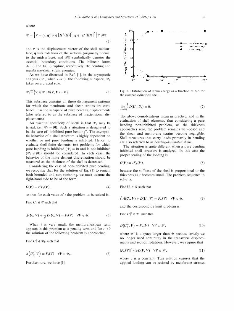
Fig. 2. Distribution of strain energy as a function of t=L for
the clamped cylindrical shell.
K.-J. Bathe et al. / Computers and Structures 75 (2000) 1±30 3
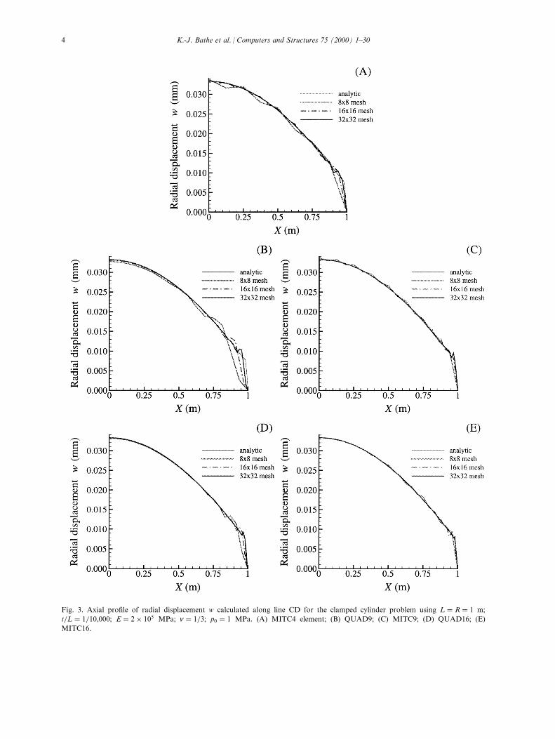
Fig. 3. Axial pro®le of radial displacement w calculated along line CD for the clamped cylinder problem using L � R � 1 m;
t=L � 1=10,000; E � 2� 105 MPa; n � 1=3; p0 � 1 MPa. (A) MITC4 element; (B) QUAD9; (C) MITC9; (D) QUAD16; (E)
MITC16.
K.-J. Bathe et al. / Computers and Structures 75 (2000) 1±304
only. Shell structures that carry loads primarily inmembrane action are also referred to as membrane-
dominated shells.
2.2. The ®nite element formulation
For the ®nite element solution, a natural way toproceed is to use displacement/rotation interpolations.Using conforming interpolations, we select Uh � U,
where Uh signi®es the ®nite element space (h denotingthe characteristic element size), and the ®nite elementproblem corresponding to Eq. (1) is:
Find Uh 2 Uh such that
t3AÿUh, V
�� tD
ÿUh, V
�� G�V � 8V 2 Uh: �12�
To measure the e�ectiveness of the solution scheme,we distinguish whether an inhibited or non-inhibitedproblem is solved. When inhibited problems are con-sidered, the solution using the above approach is e�ec-
tive as proven in [1]. However, when a non-inhibitedproblem is solved, the numerical phenomenon of``locking'' occurs which severely reduces the rate of
convergence. Namely, in this case the discrete vari-ational problem considered is
Find Uht 2 Uh such that
A�
Uht , V
�� 1
t2D�
Uht , V
�� Fb�V � 8V 2 Uh, �13�
and the convergence is highly in¯uenced by how rich
Uh is in U0: In the worst case Uh \U0 � f0g leading tototal loss of convergence
limt4 0
Uht � 0 6� lim
t4 0Ut � Ub
0: �14�
In practice, extremely ®ne meshes are needed for an
accurate solution when t is small, and the displace-ment-based ®nite element procedure becomes unpracti-cal. The remedy is to use an appropriate mixed
formulation. The aim with this approach is to interp-olate displacements and strains (or stresses) in such amanner as to have no locking of the discretization inthe non-inhibited case for any value of thickness t, and
to have, as well, a uniformly good behavior for themembrane-dominated case. Ideally, the rate of conver-gence would be optimal, independent of whether a
bending-dominated or membrane-dominated problemis considered and independent of the shell thickness.The key to reaching this optimal behavior is to use
an appropriate mixed method with the appropriate``well-balanced'' interpolations. The general mixedmethod that provides the basis of the MITC shell el-
ements is
Find Uh �ÿuh, bbbh
�2 Uh �
ÿVh, Bh
�and
Eh �nehijo2 Eh such that
8><>:t3 ~A
ÿEh, eee�V �
�� t ~D
ÿEh, eee�V �
�� G�V �
~AÿEh ÿ eee�Uh �, CCC
�� 0
~DÿEh ÿ eee�Uh �, CCC
�� 0 8V 2 Uh, CCC � �cij
2 Eh,
�15�where
Eh �nCCC � �cij
, cij 2 Eh
ij
o, �16�
and
~Aÿeee�U�, eee�V �
�� A�U, V �
~Dÿeee�U�, eee�V �
�� D�U, V �: �17�
Here Eh is the subspace of assumed strains and includes
assumed bending, membrane and shear strains. The dis-placement and strain interpolations of the elements aresummarized in Appendix A. The formulation can be de-
rived from the Hellinger±Reissner variational principle(and therefore, also from the Hu±Washizu variationalprinciple), see Appendix B. However, a stability andconvergence analysis is necessary to assess whether the
actual discretization is e�ective. This analysis is di�cultto perform analytically for a general setting, thereforewe resort to numerical assessments. For the non-inhib-
ited case, we would like that the inf-sup condition be sat-is®ed for the selected interpolations. The results of ourinf-sup condition study are presented in Ref. [7] and
show that a numerical inf-sup test is satis®ed. Our objec-tive in the following section is to give the resultsobtained in convergence studies.
3. Numerical convergence studies
The test problems we use for the convergence studiesare described in Ref. [1], where the reasons for select-ing these problems are also given. Using these pro-
blems (summarized below), we proceed in each case asfollows.For each of the test problems, we run a sequence of
meshes and depict the convergence of the relative errorin strain energy of the approximation Er versus a meshdensity indicator N, where
K.-J. Bathe et al. / Computers and Structures 75 (2000) 1±30 5
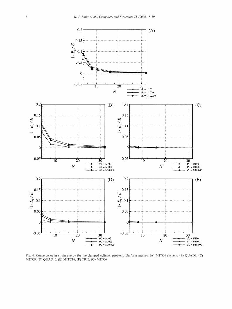
Fig. 4. Convergence in strain energy for the clamped cylinder problem. Uniform meshes. (A) MITC4 element; (B) QUAD9; (C)
MITC9; (D) QUAD16; (E) MITC16; (F) TRI6; (G) MITC6.
K.-J. Bathe et al. / Computers and Structures 75 (2000) 1±306
Er � Eÿ Eh
E, �18�
with Eh being the strain energy of the ®nite element
approximation and E being the strain energy calcu-lated using either the exact solution of the mathemat-ical model, or, when no analytical solution is available,
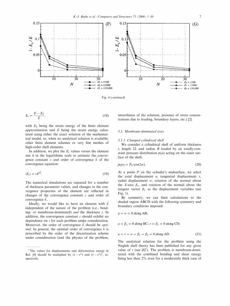
other ®nite element schemes or very ®ne meshes ofhigh-order shell elements.In addition, we plot the Er values versus the element
size h in the logarithmic scale to estimate the conver-gence constant c and order of convergence k̂ of theconvergence equation:
jErj � ch2k̂: �19�
The numerical simulations are repeated for a number
of thickness parameter values, and changes in the con-vergence properties of the element are re¯ected inchanges of the convergence constant c and order of
convergence k̂:Ideally, we would like to have an element with k̂
independent of the nature of the problem (i.e., bend-ing- or membrane-dominated) and the thickness t. In
addition, the convergence constant c should exhibit nodependence on t for each problem under consideration.Moreover, the order of convergence k̂ should be opti-
mal. In general, the optimal order of convergence k isprescribed by the order of the discretization schemeunder consideration (and the physics of the problem,
smoothness of the solution, presence of stress concen-trations due to loading, boundary layers, etc.) [2].
3.1. Membrane-dominated tests
3.1.1. Clamped cylindrical shellWe consider a cylindrical shell of uniform thickness
t, length 2L and radius R loaded by an axially-con-stant pressure distribution p�j� acting on the outer sur-face of the shell,
p�j� � P0 cos�2j�: �20�
At a point P on the cylinder's midsurface, we selectthe axial displacement u, tangential displacement v,radial displacement w, rotation of the normal about
the X-axis b1, and rotation of the normal about thetangent vector b2 as the displacement variables (seeFig. 1).
By symmetry, we can limit calculations to theshaded region ABCD with the following symmetry andboundary conditions imposed:
u � w � 0 along AB;
u � b2 � 0 along BC; v � b1 � 0 along CD;
u � v � w � b1 � b2 � 0 along AD: �21�The analytical solution for the problem using theNaghdi shell theory has been published for any given
value of t (see [8]1). The problem is membrane-domi-nated with the combined bending and shear energybeing less than 2% even for a moderately thick case of
Fig. 4 (continued)
1 The values for displacements and deformation energy in
Ref. [8] should be multiplied by �1ÿ n2� and �1ÿ n2�2, re-
spectively.
K.-J. Bathe et al. / Computers and Structures 75 (2000) 1±30 7
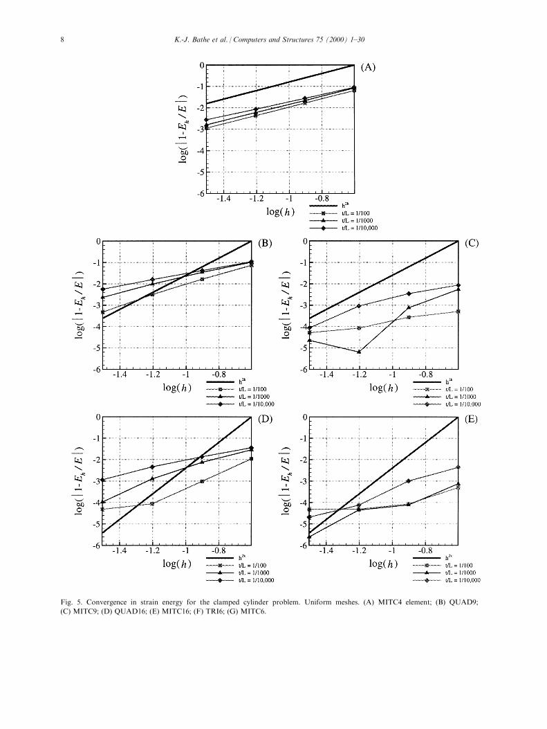
Fig. 5. Convergence in strain energy for the clamped cylinder problem. Uniform meshes. (A) MITC4 element; (B) QUAD9;
(C) MITC9; (D) QUAD16; (E) MITC16; (F) TRI6; (G) MITC6.
K.-J. Bathe et al. / Computers and Structures 75 (2000) 1±308
t=L � 1=100 (see Fig. 2) and hence we scale the applied
loading with thickness t as
P0 � p0t, �22�where p0 is a constant independent of t.First we consider uniform N�N meshes with el-
ement sides aligned with the principal directions ofcurvature, where N is the number of subdivisions per
side of the discretized domain (in our tests N � 4, 8,
16 and 32). This sequence of meshes is repeated for
each tested element for values of dimensionless thick-ness parameter t=L ranging from 1/100 to 1/10,000.Fig. 3 gives a comparison of the ®nite element
results with the analytical solution for the radial dis-placement pro®le calculated using the elements of theMITC family and the 9- and 16-node displacement-
based general shell elements (QUAD9 and QUAD16)for the case of t=L � 1=10,000:
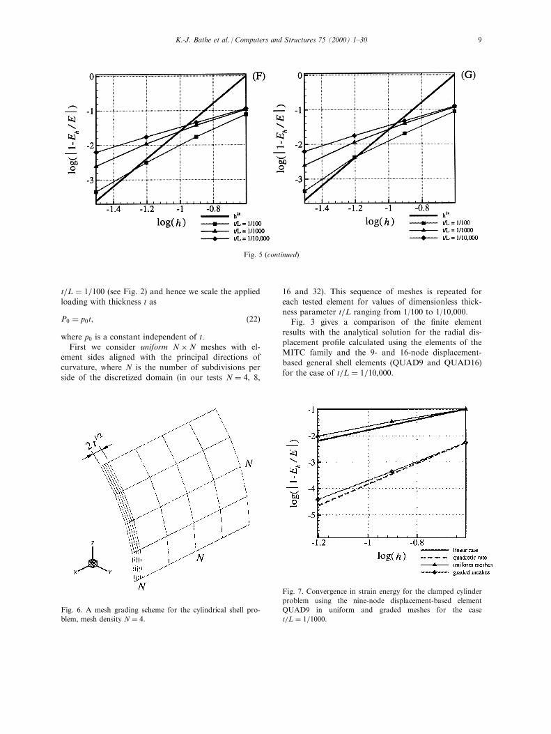
Fig. 7. Convergence in strain energy for the clamped cylinder
problem using the nine-node displacement-based element
QUAD9 in uniform and graded meshes for the case
t=L � 1=1000:Fig. 6. A mesh grading scheme for the cylindrical shell pro-
blem, mesh density N � 4:
Fig. 5 (continued)
K.-J. Bathe et al. / Computers and Structures 75 (2000) 1±30 9
All the elements perform quite well. However, somenumerical instabilities especially pronounced for thedisplacement-based elements can be observed at the
clamped end. These instabilities are due to the presence
of boundary layers and can be eliminated using gradedmeshes (as derived in Ref. [8], boundary layers play a
dominant role in a 02��tp
region at the ®xed end).Figs. 4 and 5 give the convergence in relative error
Er for the problem under consideration for a sequence
of t=L values. The six-node displacement-based el-ement is referred to as the TRI6 element.The convergence curves of the MITC4 element stay
virtually una�ected by changes in thickness t, and theelement's order of convergence k̂ is very close to itstheoretical value of k � 1:The convergence curves for the other MITC el-
ements have noticeably lower convergence constantsc than their displacement-based counterparts andreach the accuracy of 1.0% with the coarsest mesh.
Note that for the case of t=L � 1=100 the elementsdo not converge further after reaching the accuracylevel of 00:01%, which is explained by di�erences
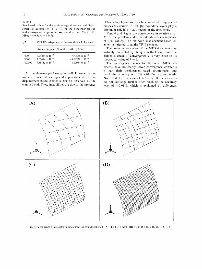
Fig. 8. A sequence of distorted meshes used for cylindrical shell. (A) The 4� 4 mesh; (B) 8� 8; (C) 16� 16; (D) 32� 32:
Table 1
Benchmark values for the strain energy E and vertical displa-
cement w at point x � 0, y � 0 for the hemispherical cap
under axisymmetric pressure. We use R � 1 m; E � 2� 105
MPa; n � 0:3; p0 � 1 MPa
t=R 1024 1D axisymmetric three-node shell elements
Strain energy E (N�mm) w�0, 0� (mm)
1/100 6:79244� 10ÿ5 ÿ7:73688� 10ÿ3
1/1000 7:62474� 10ÿ6 ÿ8:08931� 10ÿ3
1/10,000 7:88885� 10ÿ7 ÿ8:19934� 10ÿ3
K.-J. Bathe et al. / Computers and Structures 75 (2000) 1±3010
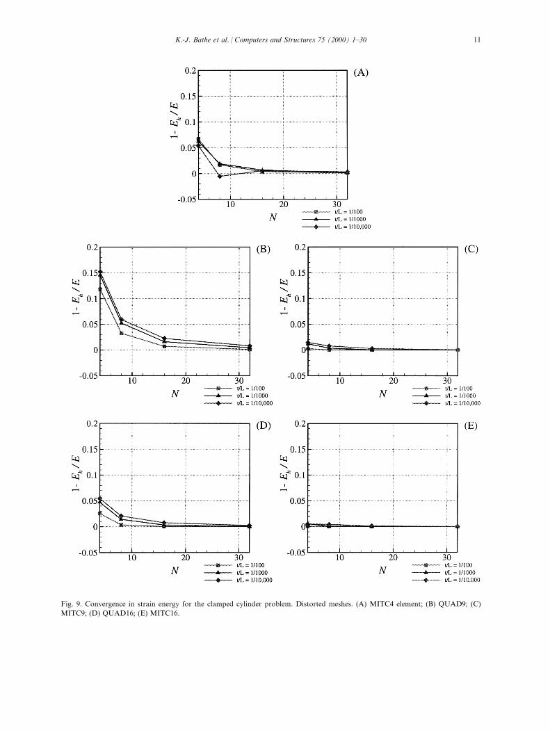
Fig. 9. Convergence in strain energy for the clamped cylinder problem. Distorted meshes. (A) MITC4 element; (B) QUAD9; (C)
MITC9; (D) QUAD16; (E) MITC16.
K.-J. Bathe et al. / Computers and Structures 75 (2000) 1±30 11

Fig. 10. Convergence in strain energy for the clamped cylinder problem. Distorted meshes. (A) MITC4 element; (B) QUAD9; (C)
MITC9; (D) QUAD16; (E) MITC16.
K.-J. Bathe et al. / Computers and Structures 75 (2000) 1±3012
between the reference (Naghdi theory) solution and
the solution to our underlying shell model [6].
As pointed out in [8], the fact that the observed con-
vergence rates are lower than the respective ``optimal''
rates (equal to the order of the polynomial interpola-
tions in the elements) may be due to the presence of
stress concentration in the boundary layer region and
can be improved using mesh grading. To identify the
e�ect of mesh grading, we consider the following mesh
grading scheme: the discretized domain is separated
into two regions Ð the boundary layer region of width
2��tp
in the X-direction, and the smooth solution region
of width equal to 1ÿ 2��tp: Both regions are then
meshed with the equal mesh density N as shown in
Fig. 6.
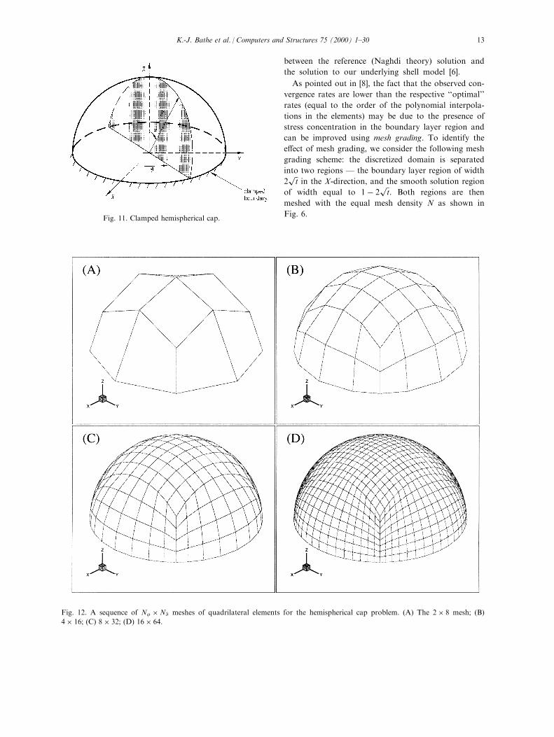
Fig. 12. A sequence of Nj �NW meshes of quadrilateral elements for the hemispherical cap problem. (A) The 2� 8 mesh; (B)
4� 16; (C) 8� 32; (D) 16� 64:
Fig. 11. Clamped hemispherical cap.
K.-J. Bathe et al. / Computers and Structures 75 (2000) 1±30 13
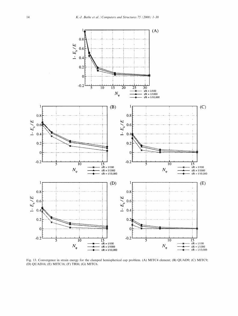
Fig. 13. Convergence in strain energy for the clamped hemispherical cap problem. (A) MITC4 element; (B) QUAD9; (C) MITC9;
(D) QUAD16; (E) MITC16; (F) TRI6; (G) MITC6.
K.-J. Bathe et al. / Computers and Structures 75 (2000) 1±3014
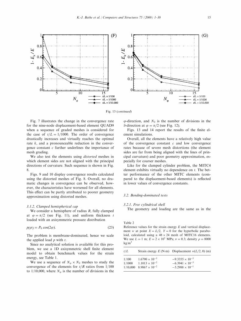
Fig. 7 illustrates the change in the convergence ratefor the nine-node displacement-based element QUAD9when a sequence of graded meshes is considered forthe case of t=L � 1=1000: The order of convergence
drastically increases and virtually reaches the optimalrate k, and a pronounceable reduction in the conver-gence constant c further underlines the importance of
mesh grading.We also test the elements using distorted meshes in
which element sides are not aligned with the principal
directions of curvature. Such sequence is shown in Fig.8.Figs. 9 and 10 display convergence results calculated
using the distorted meshes of Fig. 8. Overall, no dra-matic changes in convergence can be observed, how-ever, the characteristics have worsened for all elements.This e�ect can be partly attributed to poorer geometry
approximation using distorted meshes.
3.1.2. Clamped hemispherical cap
We consider a hemisphere of radius R, fully clampedat j � p=2 (see Fig. 11), and uniform thickness tloaded with an axisymmetric pressure distribution
p�j� � P0 cos�2j�: �23�
The problem is membrane-dominated, hence we scalethe applied load p with t.Since no analytical solution is available for this pro-
blem, we use a 1D axisymmetric shell ®nite elementmodel to obtain benchmark values for the strainenergy, see Table 1.
We use a sequence of Nj �NW meshes to study theconvergence of the elements for t=R ratios from 1/100to 1/10,000, where Nj is the number of divisions in the
j-direction, and NW is the number of divisions in theW-direction at j � p=2 (see Fig. 12).Figs. 13 and 14 report the results of the ®nite el-
ement simulations.
Overall, all the elements have a relatively high valueof the convergence constant c and low convergencerates because of severe mesh distortions (the element
sides are far from being aligned with the lines of prin-cipal curvature) and poor geometry approximation, es-pecially for coarser meshes.
Like for the clamped cylinder problem, the MITC4element exhibits virtually no dependence on t. The bet-ter performance of the other MITC elements (com-
pared to the displacement-based elements) is re¯ectedin lower values of convergence constants.
3.2. Bending-dominated tests
3.2.1. Free cylindrical shellThe geometry and loading are the same as in the
Fig. 13 (continued)
Table 2
Reference values for the strain energy E and vertical displace-
ment w at point X � L=2, Y � 0 for the hyperbolic parabo-
loid, calculated using a 48� 24 mesh of MITC16 elements.
We use L � 1 m; E � 2� 105 MPa; n � 0:3; density r � 8000
kg/m3
t=L Strain energy E (N�m) Displacement w�L=2, 0� (m)
1/100 1:6790� 10ÿ3 ÿ9:3355� 10ÿ5
1/1000 1:1013� 10ÿ2 ÿ6:3941� 10ÿ3
1/10,000 8:9867� 10ÿ2 ÿ5:2988� 10ÿ1
K.-J. Bathe et al. / Computers and Structures 75 (2000) 1±30 15
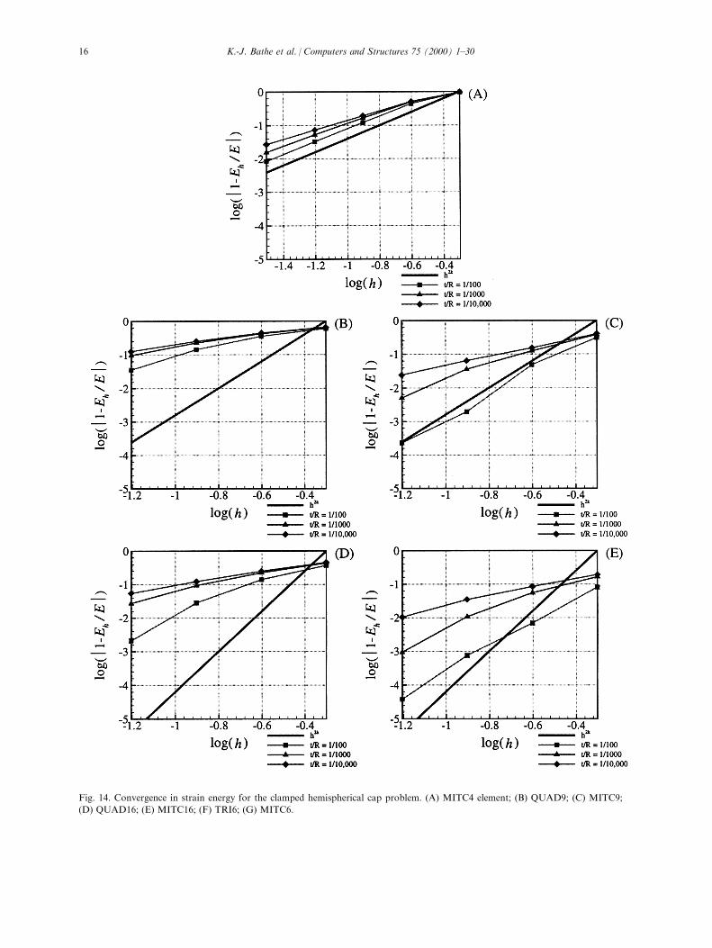
Fig. 14. Convergence in strain energy for the clamped hemispherical cap problem. (A) MITC4 element; (B) QUAD9; (C) MITC9;
(D) QUAD16; (E) MITC16; (F) TRI6; (G) MITC6.
K.-J. Bathe et al. / Computers and Structures 75 (2000) 1±3016
clamped cylinder problem considered above. The sameboundary and symmetry conditions are applicable but
we release all the ®xities along the arc AD.The bending energy prevails even for moderately
large t=L ratios Ð Fig. 15 shows that relative contri-
butions of the shear and membrane terms are essen-tially negligible.In the convergence study we use the Naghdi shell
theory solution given in Ref. [8], where a general meth-
odology of obtaining the exact solution for any given(positive) value of t is demonstrated. Because bendingis dominant in this problem, the load is rescaled as
P0 � p0t3: �24�
Fig. 16 presents a comparison of the analytical sol-ution for the axial pro®le of the radial displacement wwith the ®nite element simulation results for the t=L �1=10,000 case. The nine-node displacement-based el-ement locks and results in zero displacements for coar-ser meshes. The QUAD16 element starts o� quite far
from the analytical solution but reaches decent accu-racy for ®ner meshes. The MITC4 element displaysrobust convergence, and the higher-order MITC el-
ements produce accurate results even for relativelycoarse meshes.The convergence in strain energy using uniform
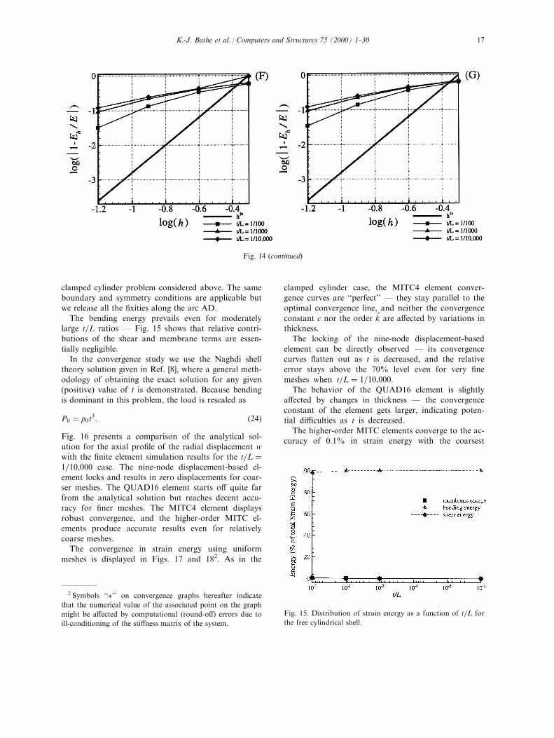
meshes is displayed in Figs. 17 and 182. As in the
clamped cylinder case, the MITC4 element conver-gence curves are ``perfect'' Ð they stay parallel to the
optimal convergence line, and neither the convergenceconstant c nor the order k̂ are a�ected by variations inthickness.
The locking of the nine-node displacement-basedelement can be directly observed Ð its convergencecurves ¯atten out as t is decreased, and the relativeerror stays above the 70% level even for very ®ne
meshes when t=L � 1=10,000:The behavior of the QUAD16 element is slightly
a�ected by changes in thickness Ð the convergence
constant of the element gets larger, indicating poten-tial di�culties as t is decreased.The higher-order MITC elements converge to the ac-
curacy of 0.1% in strain energy with the coarsest
Fig. 14 (continued)
Fig. 15. Distribution of strain energy as a function of t=L for
the free cylindrical shell.
2 Symbols ``�'' on convergence graphs hereafter indicate
that the numerical value of the associated point on the graph
might be a�ected by computational (round-o�) errors due to
ill-conditioning of the sti�ness matrix of the system.
K.-J. Bathe et al. / Computers and Structures 75 (2000) 1±30 17
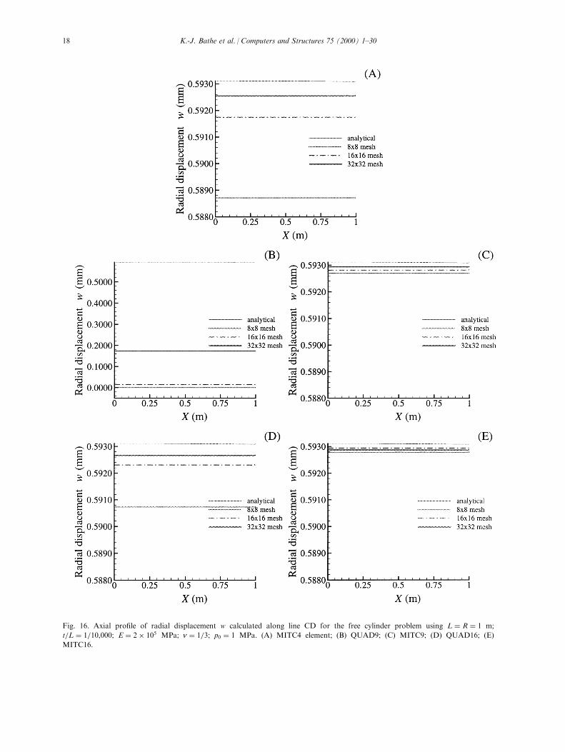
Fig. 16. Axial pro®le of radial displacement w calculated along line CD for the free cylinder problem using L � R � 1 m;
t=L � 1=10,000; E � 2� 105 MPa; n � 1=3; p0 � 1 MPa. (A) MITC4 element; (B) QUAD9; (C) MITC9; (D) QUAD16; (E)
MITC16.
K.-J. Bathe et al. / Computers and Structures 75 (2000) 1±3018
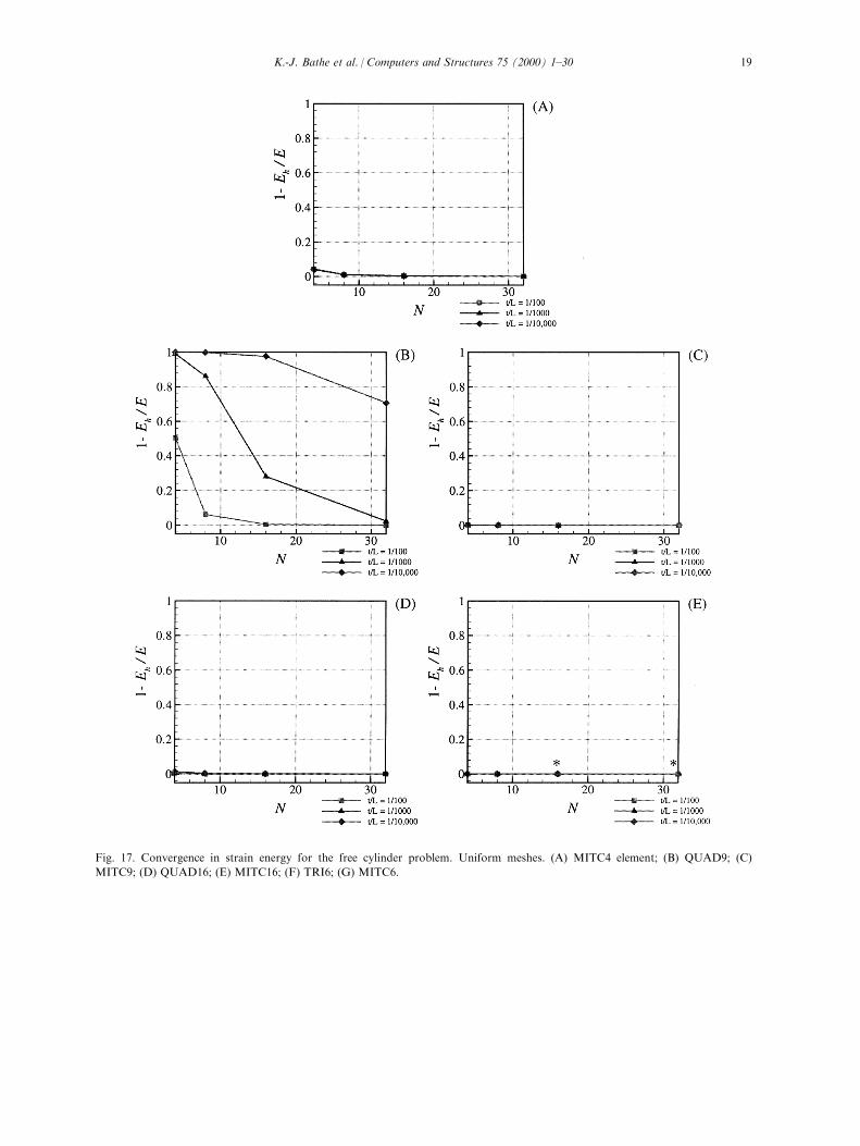
Fig. 17. Convergence in strain energy for the free cylinder problem. Uniform meshes. (A) MITC4 element; (B) QUAD9; (C)
MITC9; (D) QUAD16; (E) MITC16; (F) TRI6; (G) MITC6.
K.-J. Bathe et al. / Computers and Structures 75 (2000) 1±30 19

meshes for all the thickness values. More accurateresults could not be obtained for the case t=L �1=10,000 because of round-o� errors as a result of ill-conditioning. This solution di�culty is more likely toarise in bending-dominated problems. In these ana-
lyses, pure bending and membrane modes are associ-ated with large di�erences in sti�ness values. Note thatthis di�culty is less likely to arise when using displace-
ment-based elements because these elements do notaccurately represent the pure bending modes.As in the clamped cylinder analysis, for the t=L �
1=100 case the convergence curves ¯atten out at the
level of 0.01% because of the discrepancies betweenthe Naghdi theory solution and our three-dimensionalshell model.
Figs. 19 and 20 report the performance of the el-ements when used with the distorted meshes of Fig. 8.Overall, all the discretizations produce worse results
compared to uniform meshes. This e�ect is especiallypronounced for coarse meshes with highest distortions.However, as the meshes are re®ned, the elements reach
the accuracy levels obtained with uniform meshes.
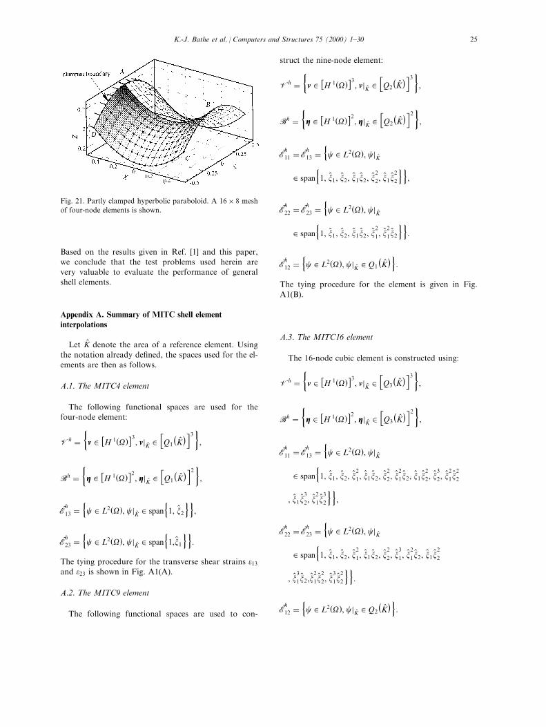
3.2.2. Partly clamped hyperbolic paraboloidThe problem was suggested in [1] as a good test
for locking behavior. The surface is de®ned as
Z � X 2 ÿ Y 2; �X, Y� 2 �� ÿ L=2; L=2��2, �25�
clamped along the side X � ÿL=2 and loaded by
self-weight.By symmetry, only one half of the surface needs
to be considered in the analysis (shaded region
ABCD in Fig. 21), with clamped boundary con-
ditions along AD and symmetry conditions along
AB.
For the ®nite element analysis we use sequences
of N�N=2 meshes, where N is the number of sub-
divisions along the X-axis. A typical 16� 8 mesh of
four-node elements is shown in Fig. 21. These
meshes are aligned with the sides of the discretized
domain, and not with the asymptotic directions [1].
The analytical solution for this problem is not
available, and we have to study the convergence to
reference strain energy values obtained with a very
®ne mesh of shell ®nite elements. Table 2 reports
such results for the strain energy and vertical dis-
placement at point X � L=2, Y � 0, calculated using
a 48� 24 mesh of MITC16 elements. Note that
since the self-weight loading is proportional to
thickness, the strain energy scales as 1=t, while dis-
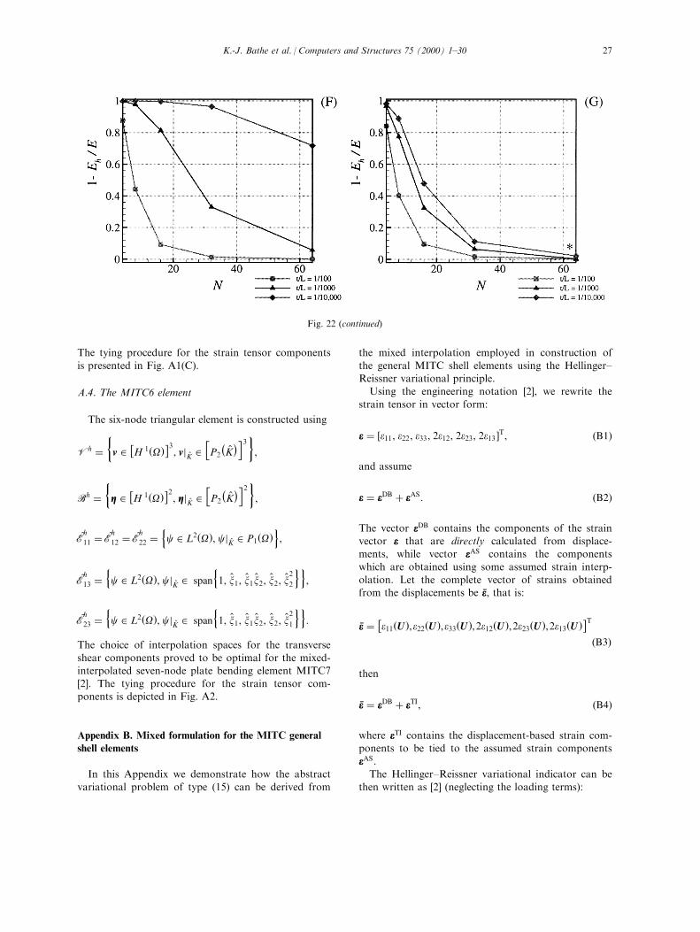
placements scale as 1=t2:Figs. 22 and 23 report the convergence in strain
energy to the values of Table 2. As in the previous
case, the nine-node displacement-based element dis-
plays severe locking Ð for t=L � 1=10,000 the error
in strain energy stays above 90% even for the ®nest
mesh of 32� 16 elements, and its convergence con-
stant c noticeably shifts with variations in thickness.
A milder form of locking can be also observed
for the QUAD16 element Ð its convergence con-
stant increases by an order of magnitude for every
decrease in t.
The MITC4 element produces good results on the
absolute scale, however, the graphs in the logarithmic
scale (Fig. 23(A)) show slow convergence. These di�-
Fig. 17 (continued)
K.-J. Bathe et al. / Computers and Structures 75 (2000) 1±3020
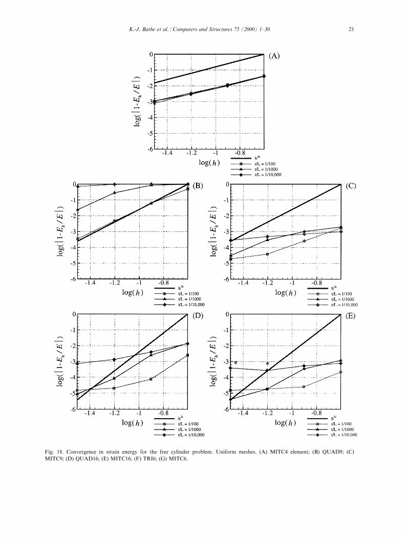
Fig. 18. Convergence in strain energy for the free cylinder problem. Uniform meshes. (A) MITC4 element; (B) QUAD9; (C)
MITC9; (D) QUAD16; (E) MITC16; (F) TRI6; (G) MITC6.
K.-J. Bathe et al. / Computers and Structures 75 (2000) 1±30 21

culties can be explained by poor geometric approxi-mation properties achieved with low-order elements forcomplex surface geometries.
The higher-order MITC elements show good conver-gence with little dependence on changes in the thick-ness of the shell structure.
4. Concluding remarks
In this paper we have presented a study of the con-vergence behavior of the MITC shell elements. Theproblems used in the convergence study were discussedin detail in Ref. [1].
The evaluation of the MITC shell elements showsthat the elements are e�ective in membrane- and bend-ing-dominated shell problems and can thus be
employed in general shell analysis situations.For the membrane-dominated problems, the MITC el-
ements produce results no worse and often signi®cantly
better than the displacement-based elements, and showrobust convergence properties with low dependence onthe thickness parameter t.For the bending-dominated problems, displacement-
based elements, of course, exhibit severe locking, whilethe MITC elements show good performance androbustness.
The optimal convergence rate has not necessarilybeen observed, but this is probably largely due toboundary layers (as shown in the case of the mem-
brane-dominated cylinder problem).Regarding the test problems, we have made the fol-
lowing general observations:
. The clamped cylinder problem has proved to be
an e�ective test for membrane-dominated beha-
vior. However, the presence of boundary layers at
the ®xed edges might induce (localized) instabil-
ities in numerical solutions and makes interpret-
ation of numerical results somewhat di�cult.
To avoid this complication, graded meshes
re®ned in the boundary layer regions can be
employed.
. The clamped hemispherical cap problem can be used
to test the performance of quadrilateral elements but
the elements will be quite distorted if the complete
shell is discretized. Of course, only a section of a
few degrees could be used. The advantage of the
problem is that a doubly-curved shell is considered
and in practice, of course, distorted elements are
commonly used.
. The free cylinder problem should be considered as
the ®rst and basic test for locking in bending-domi-
nated situations. Indeed, the space of pure bending
displacements U0 has a simple functional (poly-
nomial) form, and thus only elements with relatively
poor approximation properties would exhibit lock-
ing.
. From our experience, the partly clamped hyperbolic
paraboloid problem is an excellent test for locking in
bending-dominated situations. The geometry of the
shell is more general than a surface of zero Gaussian
curvature and the problem is more realistic than an
elliptic surface with free boundary. In addition, the
symmetry in the problem allows to use relatively ®ne
meshes, and thus, obtain sound convergence curves.
Fig. 18 (continued)
K.-J. Bathe et al. / Computers and Structures 75 (2000) 1±3022
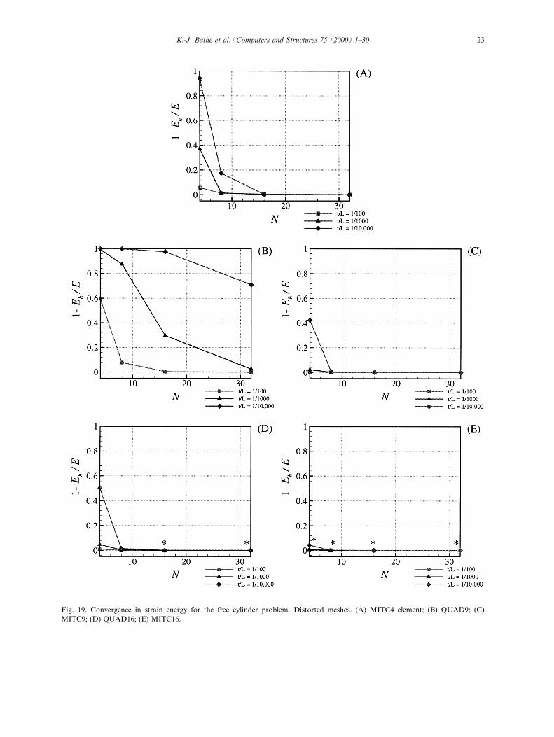
Fig. 19. Convergence in strain energy for the free cylinder problem. Distorted meshes. (A) MITC4 element; (B) QUAD9; (C)
MITC9; (D) QUAD16; (E) MITC16.
K.-J. Bathe et al. / Computers and Structures 75 (2000) 1±30 23
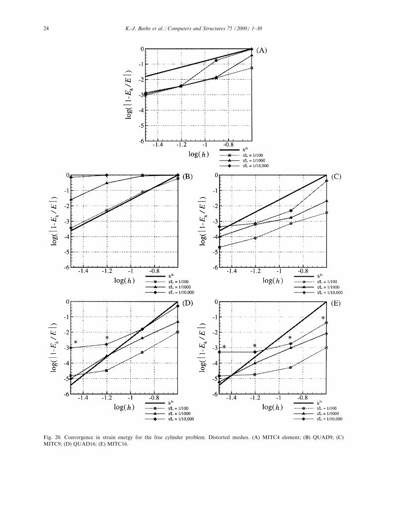
Fig. 20. Convergence in strain energy for the free cylinder problem. Distorted meshes. (A) MITC4 element; (B) QUAD9; (C)
MITC9; (D) QUAD16; (E) MITC16.
K.-J. Bathe et al. / Computers and Structures 75 (2000) 1±3024
Based on the results given in Ref. [1] and this paper,we conclude that the test problems used herein arevery valuable to evaluate the performance of general
shell elements.
Appendix A. Summary of MITC shell element
interpolations
Let K̂ denote the area of a reference element. Using
the notation already de®ned, the spaces used for the el-ements are then as follows.
A.1. The MITC4 element
The following functional spaces are used for thefour-node element:
Vh ��
v 2�H 1�O�
�3, vjK̂ 2
hQ1
ÿK̂�i3�
,
Bh ��ZZZ 2
�H 1�O�
�2, ZZZjK̂ 2
hQ1
ÿK̂�i2�
,
~Eh
13 �nc 2 L2�O�, cjK̂ 2 span
n1, x̂2
oo,
~Eh
23 �nc 2 L2�O�, cjK̂ 2 span
n1,x̂1
oo:
The tying procedure for the transverse shear strains e13and e23 is shown in Fig. A1(A).
A.2. The MITC9 element
The following functional spaces are used to con-
struct the nine-node element:
Vh ��
v 2�H 1�O�
�3, vjK̂ 2
hQ2
ÿK̂�i3�
,
Bh ��ZZZ 2
�H 1�O�
�2, ZZZjK̂ 2
hQ2
ÿK̂�i2�
,
~Eh
11 � ~Eh
13 �nc 2 L2�O�, cjK̂
2 span
n1, x̂1, x̂2, x̂1x̂2, x̂
2
2, x̂1x̂2
2
oo,
~Eh
22 � ~Eh
23 �nc 2 L2�O�, cjK̂
2 span
n1, x̂1, x̂2, x̂1x̂2, x̂
2
1, x̂2
1x̂2
oo:
~Eh
12 �nc 2 L2�O�, cjK̂ 2 Q1
ÿK̂�o:
The tying procedure for the element is given in Fig.
A1(B).
A.3. The MITC16 element
The 16-node cubic element is constructed using:
Vh ��
v 2�H 1�O�
�3, vjK̂ 2
hQ3
ÿK̂�i3�
,
Bh ��ZZZ 2
�H 1�O�
�2, ZZZjK̂ 2
hQ3
ÿK̂�i2�
,
~Eh
11 � ~Eh
13 �nc 2 L2�O�, cjK̂
2 span
n1, x̂1, x̂2, x̂
2
1, x̂1x̂2, x̂2
2, x̂2
1x̂2, x̂1x̂2
2, x̂3
2, x̂2
1x̂2
2
, x̂1x̂3
2, x̂2
1x̂3
2
oo,
~Eh
22 � ~Eh
23 �nc 2 L2�O�, cjK̂
2 span
n1, x̂1, x̂2, x̂
2
1, x̂1x̂2, x̂2
2, x̂3
1, x̂2
1x̂2, x̂1x̂2
2
, x̂3
1x̂2,x̂2
1x̂2
2, x̂3
1x̂2
2
oo:
~Eh
12 �nc 2 L2�O�, cjK̂ 2 Q2
ÿK̂�o:
Fig. 21. Partly clamped hyperbolic paraboloid. A 16� 8 mesh
of four-node elements is shown.
K.-J. Bathe et al. / Computers and Structures 75 (2000) 1±30 25
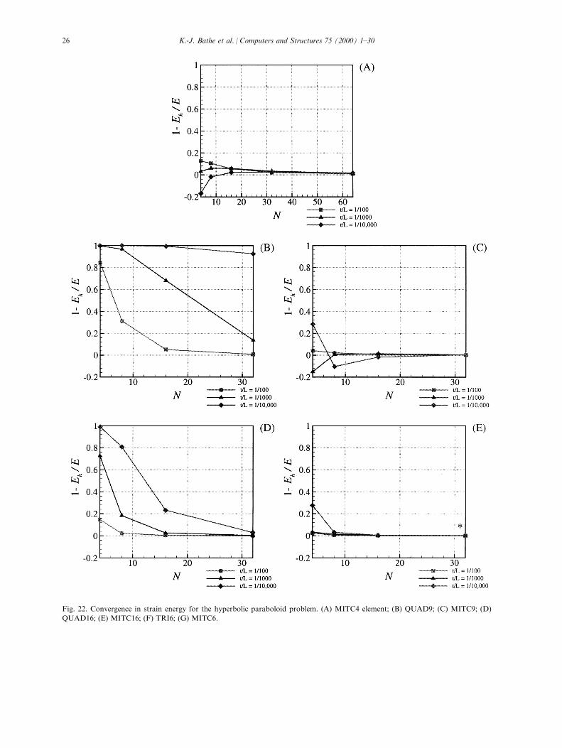
Fig. 22. Convergence in strain energy for the hyperbolic paraboloid problem. (A) MITC4 element; (B) QUAD9; (C) MITC9; (D)
QUAD16; (E) MITC16; (F) TRI6; (G) MITC6.
K.-J. Bathe et al. / Computers and Structures 75 (2000) 1±3026
The tying procedure for the strain tensor components
is presented in Fig. A1(C).
A.4. The MITC6 element
The six-node triangular element is constructed using
Vh ��
v 2�H 1�O�
�3, vjK̂ 2
hP2
ÿK̂�i3�
,
Bh ��ZZZ 2
�H 1�O�
�2, ZZZjK̂ 2
hP2
ÿK̂�i2�
,
~Eh
11 � ~Eh
12 � ~Eh
22 �nc 2 L2�O�, cjK̂ 2 P1�O�
o,
~Eh
13 �nc 2 L2�O�, cjK̂ 2 span
n1, x̂1, x̂1x̂2, x̂2, x̂
2
2
oo,
~Eh
23 �nc 2 L2�O�, cjK̂ 2 span
n1, x̂1, x̂1x̂2, x̂2, x̂
2
1
oo:
The choice of interpolation spaces for the transverse
shear components proved to be optimal for the mixed-interpolated seven-node plate bending element MITC7[2]. The tying procedure for the strain tensor com-ponents is depicted in Fig. A2.
Appendix B. Mixed formulation for the MITC general
shell elements
In this Appendix we demonstrate how the abstractvariational problem of type (15) can be derived from
the mixed interpolation employed in construction of
the general MITC shell elements using the Hellinger±Reissner variational principle.Using the engineering notation [2], we rewrite the
strain tensor in vector form:
eee � �e11, e22, e33, 2e12, 2e23, 2e13 �T, �B1�
and assume
eee � eeeDB � eeeAS: �B2�
The vector eeeDB contains the components of the strainvector eee that are directly calculated from displace-ments, while vector eeeAS contains the components
which are obtained using some assumed strain interp-olation. Let the complete vector of strains obtainedfrom the displacements be Åeee, that is:
Åeee � �e11�U�,e22�U�,e33�U�,2e12�U�,2e23�U�,2e13�U��T�B3�
then
Åeee � eeeDB � eeeTI, �B4�
where eeeTI contains the displacement-based strain com-ponents to be tied to the assumed strain components
eeeAS:The Hellinger±Reissner variational indicator can be
then written as [2] (neglecting the loading terms):
Fig. 22 (continued)
K.-J. Bathe et al. / Computers and Structures 75 (2000) 1±30 27
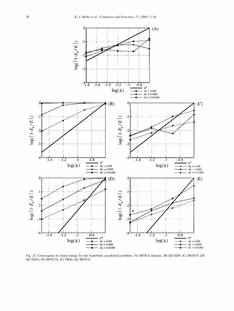
Fig. 23. Convergence in strain energy for the hyperbolic paraboloid problem. (A) MITC4 element; (B) QUAD9; (C) MITC9; (D)
QUAD16; (E) MITC16; (F) TRI6; (G) MITC6.
K.-J. Bathe et al. / Computers and Structures 75 (2000) 1±3028
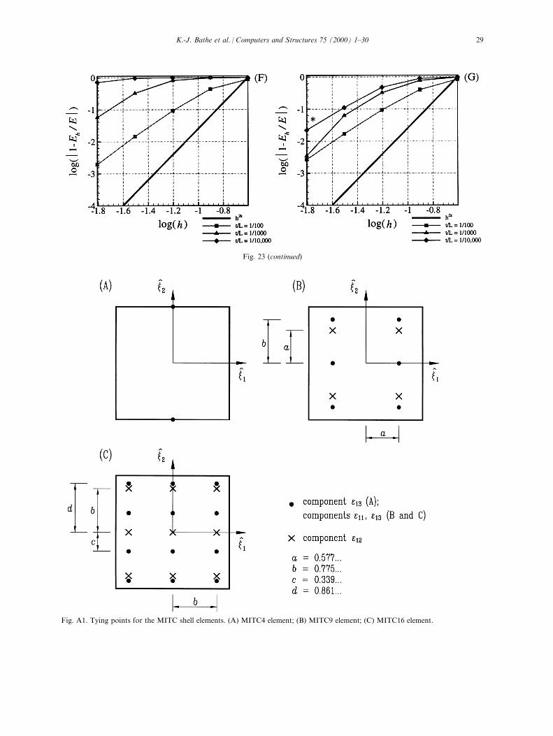
Fig. 23 (continued)
Fig. A1. Tying points for the MITC shell elements. (A) MITC4 element; (B) MITC9 element; (C) MITC16 element.
K.-J. Bathe et al. / Computers and Structures 75 (2000) 1±30 29

PHR�U, eee� � ÿ 1
2
�V
eeeTCeee dV��V
eeeTCÅeee dV
� 1
2
�V
�eeeDB �TCeeeDB dV
ÿ 1
2
�V
�eeeAS �TCeeeAS dV
��V
�eeeDB �TCeeeTI dV
��V
�eeeAS �TCeeeTI dV, �B5�
where C is the matrix of constitutive relations.Invoking the stationarity conditions for PHR with
respect to U and eeeAS,
dPHR
ÿU, eeeAS
�� 0 �B6�
we obtain:�V
�deeeDB �TCÅeee dV��V
�deeeTI �TCeee dV � 0,
�V
�deeeAS �TC�eeeTI ÿ eeeAS � dV � 0: �B7�
Note that when all the components of the strain tensor
are tied, i.e., eeeDB � deeeDB � 0, the formulation becomes:�V
�deeeTI �TCeeeAS dV � 0,
�V
�deeeAS �TC�eeeTI ÿ eeeAS � dV � 0: �B8�
This mixed formulation pertaining to the underlying
mathematical model (discussed in Ref. [6]) is the for-mulation in Eq. (15) for the Naghdi shell model.The second line of Eq. (B7) de®nes the ``tying'' pro-
cedure by which eeeAS is obtained from eeeTI: For the
MITC elements we directly use eeeAS � J�eeeTI�, whereJ�eeeTI� denotes the assumed interpolation of eeeTI in thestrain space. Hence, the integral form of Eq. (B8) is
equivalent to the MITC formulation if�V
�deeeAS �TCeeeTI dV ��V
�deeeAS �TCJ�eeeTI � dV: �B9�
This relation holds true if the integral on the left-hand
side can be exactly evaluated by using the values ofdeeeAS and eeeTI at the tying points only. Considering planeelements, this clearly holds for rectangular MITC9 and
MITC16 elements for which the tying points corre-spond to Gauss integration points that can be used tointegrate the quantity �deeeAS�TCeeeTI exactly. Eq. (B9) can
be shown to hold for the MITC4 and MITC6 elementsas well by computing both sides analytically (usingsymbolic calculus software, for example).
References
[1] Chapelle D, Bathe KJ. Fundamental considerations for
the ®nite element analysis of shell structures. Computers
and Structures 1998;66:19±36.
[2] Bathe KJ. Finite element procedures. Englewood Cli�s,
NJ: Prentice-Hall, 1996.
[3] Dvorkin EN, Bathe KJ. A continuum mechanics based
four-node shell element for general nonlinear analysis.
Eng Comput 1984;1:77±88.
[4] Bucalem ML, Bathe KJ. Higher-order MITC general shell
elements. Int J Num Meth Eng 1993;36:3729±54.
[5] Naghdi PM. Foundations of elastic shell theory. In:
Progress in solid mechanics, vol. 4. Amsterdam: North-
Holland, 1963. p. 1±90.
[6] Chapelle D, Bathe KJ. On general shell ®nite elements
and mathematical shell models. In: Topping BHV, editor.
Advances in ®nite element procedures and techniques.
Edinburgh, Scotland: Civil-Comp Press, 1998. p. 25±30.
[7] Bathe KJ, Iosilevich A, Chapelle D. An inf-sup test for
shell ®nite elements. Computers and Structures (in press).
[8] PitkaÈ ranta J, Leino Y, Ovaskainen O, Piila J. Shell defor-
mation states and the ®nite element method: a benchmark
study of cylindrical shells. Comp Meth Appl Mech Eng
1995;128:81±121.
Fig. A2. Tying points for the six-node mixed-interpolated
shell element MITC6.
K.-J. Bathe et al. / Computers and Structures 75 (2000) 1±3030