an example of geometric origami design with benefit of ... · an example of geometric origami...
TRANSCRIPT

An example of geometric origami design with
benefit of graph enumeration algorithms
David Dureisseix
Univ Lyon, INSA Lyon (France)
Abstract: This article is concerned with an example of complex planar geom-etry arising from flat origami challenges. The complexity of solution algorithmsis illustrated, depending on the depth of the initial analysis of the problem,starting from brute force enumeration, up to the equivalence to a dedicatedproblem in graph theory. This leads to algorithms starting from an untractablecase on modern computers, up to a run of few seconds on a portable personalcomputer. This emphasizes the need for a prior analysis by humans before con-sidering the assistance of computers for design problems. The graph problem isan enumeration of spanning trees from a grid graph, leading to a coarse scaledescription of the geometry of the paper edge on the flat-folded state.
Keywords: spanning tree enumeration; NP-hard; planar geometry; complex-ity; folding; computational origami
1 Introduction
Origami (paperfolding without cutting nor gluing) and especially flat-foldedmodel design, strongly relies on planar geometry. Color-changing technique,using appropriately a paper with one color on a face and a second color onthe other face, adds some challenges to the previous model design. The mostdemanding cases use numerous and alternated color changes on the flat-foldedstate of the paper, and making a chessboard (or checkered patterns) is amongthe hardest problems, provided that one adds the constraint of starting from asingle square sheet of paper. Indeed, starting from a narrow strip of two-coloredpaper, or from several separated sheets (a technique known as modular origami),drastically reduces the difficulty of designing a checkered pattern.
Several designs appeared during the past 30 years, see Table 1, and thequestion of the optimality was settled: to get a n×n checkered pattern, what isthe minimal size of the initial square sheet of paper? In its present general form,this question is still open. Nevertheless, once a design is completed, an upperbound for the optimal initial square sheet size is made available. Some estimateswere also given: with the sensible assumption that a color-change always appears
1
arX
iv:1
510.
0749
9v4
[cs
.CG
] 2
7 M
ay 2
017
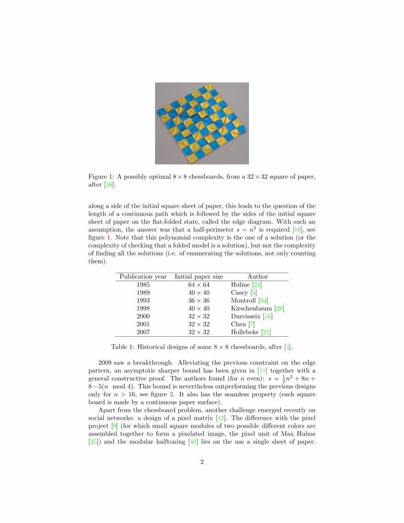
Figure 1: A possibly optimal 8× 8 chessboards, from a 32× 32 square of paper,after [16].
along a side of the initial square sheet of paper, this leads to the question of thelength of a continuous path which is followed by the sides of the initial squaresheet of paper on the flat-folded state, called the edge diagram. With such anassumption, the answer was that a half-perimeter s = n2 is required [16], seefigure 1. Note that this polynomial complexity is the one of a solution (or thecomplexity of checking that a folded model is a solution), but not the complexityof finding all the solutions (i.e. of enumerating the solutions, not only countingthem).
Publication year Initial paper size Author1985 64× 64 Hulme [24]1989 40× 40 Casey [5]1993 36× 36 Montroll [34]1998 40× 40 Kirschenbaum [28]2000 32× 32 Dureisseix [16]2001 32× 32 Chen [7]2007 32× 32 Hollebeke [21]
Table 1: Historical designs of some 8× 8 chessboards, after [4].
2009 saw a breakthrough. Alleviating the previous constraint on the edgepattern, an asymptotic sharper bound has been given in [11] together with ageneral constructive proof. The authors found (for n even): s = 1
2n2 + 8n +
8−5(n mod 4). This bound is nevertheless outperforming the previous designsonly for n > 16, see figure 2. It also has the seamless property (each squareboard is made by a continuous paper surface).
Apart from the chessboard problem, another challenge emerged recently onsocial networks: a design of a pixel matrix [42]. The difference with the pixelproject [9] (for which small square modules of two possible different colors areassembled together to form a pixelated image, the pixel unit of Max Hulme[25]) and the modular halftoning [44] lies on the use a single sheet of paper.
2

Figure 2: Bounds on complexity for the general problem of the n×n checkeredpattern.
Moreover, as for a LED matrix, each board square should be able to changeits color simply (e.g. with a single paper flip) and independently of the others.It appears that the proposed 8× 8 pixel-matrix design can be obtained from arectangular paper (an 8× 66 strip is possible, a longer strip renders it easier; itis not known to the author if a shorter one is feasible). Therefore, the challengeof the design of an optimal 8× 8 pixel matrix from a square sheet was settled.
This article focus on this last question, together with the possibility of usingcomputers to check the possibilities and to help for designing, as well as thecomplexity of the associated design algorithms.
2 Flipping mechanism and optimality challenge
The main argument used herein is to reuse the same edge assumption as for theearly chessboard: we still rely on the initial paper edge for the color-change, sinceit still produces the best known paper optimality, at least for the 8× 8 design.Furthermore, a second assumption is needed for the flipping mechanism allowinga color-change on each board square independently (and a simple single move);we suggest to design an articulation on the diagonal of the board square. Using acorner or a side of the initial paper square therefore leads to two different foldingdesigns; figure 3 presents the elementary folding mechanisms to generate suchflaps. The folded crease allowing each flap has a length of
√2 and a perimeter
length consumption of 2, both for the corner and for the side mechanisms.The former designs for classical static chessboard also possess some diagonal
flaps color-changing square board, but not for all of them. The new design [11]also possess flaps; nevertheless, they are square flaps along a board square edgeand are not independent on each board square (changing the overlap order woulddo the job, but is not considered herein as a simple color-changing mechanism).
3
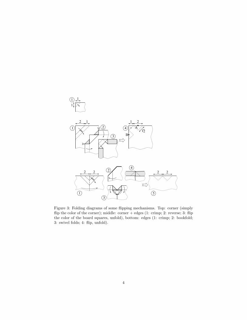
Figure 3: Folding diagrams of some flipping mechanisms. Top: corner (simplyflip the color of the corner); middle: corner + edges (1: crimp; 2: reverse; 3: flipthe color of the board squares, unfold), bottom: edges (1: crimp; 2: bookfold;3: swivel folds; 4: flip, unfold).
4

If this flipping mechanism is feasible, it will therefore require the use of 4corner mechanisms plus n2 − 4 side mechanisms, leading to a semiperimeterwith a minimum length of n2, that is no more than the straight chessboard.One could therefore challenge that an 8× 8 color-changing pixel-matrix can bedesigned with the same efficiency as for the best 8 × 8 chessboard, i.e. with a32× 32 square of two-colored paper.
In case of success, this would also exemplify the raise in difficulty by pre-scribing a design from a square sheet of paper. Indeed, the aforementioned strip(8×66 rectangular paper) leads to a mean thickness of the folded model (countedas the average number of superimposed paper layers) to be t = (8×66)/(8×8) =8.25, while for the square paper, it would raise for the hopefully best case tot = (32× 32)/(8× 8) = 16.
3 Design principles for the pixel matrix
To design such a geometric origami model, straight force of computers is notyet sufficient. Indeed, for flat-folding problems, the complexity of the task isvery rapidly overwhelming. An underlying basic question concerns the creasepattern, which is the drawing on an unfolded flat sheet of paper of the crease lo-cations as well as their assignments (mountain or valley): given a crease pattern,will it fold flat? This question appeared to be not trivial. Some general condi-tions can be stated [26] but they are hardly usable in practice; some necessarylocal constraints around each vertex (i.e. each crease intersection) [22, 14, 1, 17]are nevertheless easier to express, and one could expect relying on comput-ers for running algorithms that could check the foldability. Unfortunately, intheir general forms, these problems are hard to solve. For instance, the simplecompanion problem of layer ordering, even with a given crease assignment, todecide if the model will fold flat is NP-complete [2]. General case is thereforeuntractable, though some tools are already available to help designing or check-ing rigid origami foldability, such as TreeMaker [31, 32], using circle packing[12], and Rigid Origami Simulator [40, 41], using mechanism theory.
Design searching therefore needs for intermediate steps in the genuine prob-lem, that may lead to more amenable solution strategies. The proposal for thepixel-matrix design is to split the problem into simpler subproblems: after theprevious design for a flipping mechanism on the paper edge, one could focus onan edge path determination, and on a fold propagation from the edge to thecenter of the paper.
3.1 Generalized edge pattern and search complexity
With the previous flipping mechanism, a first subproblem concerns the place-ment on the flat-folded model (i.e. the n × n chessboard pattern) of the artic-ulation of the flap for each board square. They should split each board squarein half along one of its diagonal, and since they are connected to a paper initialedge as in figure 3, the set of all those crease locations should (i) be a continuous
5

closed curve (it should possess only one closed loop), (ii) without crossing (buttouching is allowed) since it should be on the top surface of the folded model,(iii) passing through one diagonal of each of the n2 board squares. This pathcould be named generalized edge pattern in reference to its counterpart for theclassical chessboard [16].
As a guide for the design, the paperfolder is therefore interested in selectingsuch a path that could be mapped onto the edge of the initial square sheet ofpaper. He could also select it with additional considerations such as symmetries(that may allow to reduced the size of the problem), estimates the difficulty ofthe task, etc. A useful information is therefore the enumeration of all possiblepaths. This part of the problem is prone to computerization and is discussed inthe following.
3.1.1 Brute force approach
Without a deeper analysis, and since the path splits all the board squares in half,but with two diagonal possibilities each time, a crude enumerating approachconsists in selecting one of the two possible diagonals per board square, forall the possible configurations, and testing for the aforementioned constraints.This kind of problem is usually not polynomial in time, since the difficulty liesin the number of possible selections of a set of n2 diagonals: there are p1 = 2(n
2)
sets to test. This number increases rapidly with the size n; Table 2 reports thecorresponding values; the 8 × 8 case seems not to be possible to perform thisway1.
n p1 p2 p3 N N
2 16 1 1 1 04 65 536 16 4 4 06 68 719 476 736 4 096 495 192 11
≈ 69 billions8 18 446 744 073 709 551 616 16 777 216 1 307 504 100 352 3 924
≈ 18 billion billions ≈ 17 millions ≈ 1.3 millions10 557 568 000
≈ 558 millions
Table 2: Number of cases to generate and test, depending on the problem entrysize n.
3.1.2 Path growing approach
A second approach consists of making a non-crossing path grows in a continuousway, by step of one diagonal at a time (called a segment in the following) andexploring all alternatives, i.e. the possible different orientations for the nextsegment, with backtracking. Due to the closed and continuous characters of thepath, not all the diagonal sites are feasible, opportunely reducing the problem
1The number of cases is close to the solution of the famous ‘wheat and chessboard’ problem
6

Figure 4: Path location for the generalized edge pattern of the 4×4 pixel-matrixproblem, and the corresponding graph. The only solution, but which does notallow any corner placement is also depicted.
Figure 5: Path location for the generalized edge pattern of the 6 × 6 pixel-matrix problem, and the corresponding graph. One solution among others isalso depicted.
size: corner board squares could be split in only one way (otherwise there isa pending segment at the corner, preventing the path to be continuous), andfor an even n (only considered in the following), the constraint propagates toallow only one feasible diagonal per board square. The possible location forthe path is depicted for a 4 × 4 problem in figure 4 (left), for a 6 × 6 problemin figure 5 (left), and for an 8 × 8 problem in figure 6 (left). Moreover all thesuccessive segments are connected at right angle. This could be understood asa consequence of the path requirements: if two segments are aligned, the pathshould also contain a segment going perpendicular at the connection node (to fillall the board edges) see figure 7; this segment should have a pending end-point(it cannot cross the previous sub-path of the two segments); therefore, the pathcould not be closed.
Figure 6: Path location for the generalized edge pattern of the 8 × 8 pixel-matrix problem, and the corresponding graph. One solution among others isalso depicted.
7

Figure 7: Local connections of the path when segments 1 and 2 are aligned. Left:segment 3 cannot be connected to the previous path of segments 1 and 2 dueto its orientation; right: segment 3 with the converse orientation has a pendingend point and the path cannot be closed. Conclusion: successive segments 1and 2 cannot be aligned.
All in all, these criteria reduce the problem to the choice between two connec-
tions at each missing point, leading to a number of possibilities of p2 = 2( 12n
2−n).For each, the single-loop constraint should be tested. Though this number stillgrows rapidly with n, the 8 × 8 case is now possible to be computerized, seeTable 2.
The author programmed an algorithm to solve the path search problem bymaking the path grows, which is a somehow engineering approach to find a wayto get a solution. From the p2 = 16 777 216 cases, only 20 826 are single-loopnon-crossing paths. Among these last ones, some are symmetric to others, inthe symmetry group of the square (dihedral group of order 8). Once eliminatingthem, the number of solutions reduces to 12 600.
3.1.3 Pathway to the graph theory
Due to the closed, continuous and non-crossing characters of the path, it splitsthe n × n square domain in an outer and an interior subdomains. These sub-domains are composed by cells that are the union of half diagonal parts of theboard squares sharing a corner (called vertex in the following), i.e. squares tiltedby 45 degrees; figures 4 and 6 (right) depict these two subdomains in differentgray levels. Focusing on the interior gray subdomain, connected by cell cornersand whose contour is the searched path, an equivalent graph can be defined.The graph vertices are the aforementioned ν = (n/2)2 previous vertices, andthe arcs relate all the vertices, without loop, containing the connectivity infor-mation of the cells. This is therefore a spanning tree of the square grid graphwith ν vertices, known to have ν− 1 arcs [43]. The interest of this new problemformulation is to be able to rely on numerous previous works on graphs.
The problem of finding all the possible paths is therefore casted into a span-ning tree enumeration. N denotes the number of these spanning trees, and isreported in Table 2. It can be obtained with the Kirchhoff’s matrix-tree theorem[27, 6, 15]. For the 4× 4 pixel matrix, one gets N = 4 (but all are symmetric ofthe first one — mirroring or rotating — so only 1 spanning tree is interesting,leading to a single solution for the path). This number also increases rapidlywith the size of the board: for the 8 × 8 pixel matrix, one gets N = 100 352.
8

This is a particular integer sequence known as A007341 [39, 35].A first approach lies in choosing the arcs of a possible spanning tree between
those of the grid graph, and testing for each the nodes involved and the acyclic-ity. The number of graphs to be tested is then p3 = Cν−1e = e!
(e−ν+1)!(ν−1)! ,
where e = n(n/2− 1) is the number of arcs of the grid graph, see Table 2.This approach is nevertheless not the most efficient. There are several avail-
able algorithms for enumerating all these trees, and their complexity are in-creasing as O(N + ν + e) (and p3 is known to bound above N)2. Few efficientstand-alone implementations have been made available, with the notable excep-tion of the grayspspan code of D. Knuth [29, 36] that has been used herein.A graph contains essentially a topogical information, but with the node coor-dinates for the problem under concern, a geometrical information is available,and allows to detect the trees that are symmetric to an other one, as previously.Once eliminating them, the number of solutions reduces from N = 100 352 to12 600 (indeed, the same as for the previous approach, which is a good cross-check of the implementations).
Traducing the problem in term of graphs has two main effects: first it restatethe problem as a more generic one for which more efficient algorithms are avail-able; second it reduces its size since the graph is built on a coarser grid than thepath of the paper edge. This second feature is kind of a multiscale problem asit can be seen on figure 6 (right). The involved scales could be quantified by thelengths of the tree and path: for the spanning tree, the length of its ν− 1 edgesis 2(ν − 1) while the length of the generalized edge path is
√2n2. The length
difference is related to the microscale so that the characteristic scale ratio is(n2 −
√2(ν − 1))/n2 ≥ 1 −
√2/4 ≈ 0.646 (the asymptotic value for large n).
The scales are therefore hardly separable. It would certainly be interesting tobe able to find even coarser models to reduce further the size of the problem,but such upscalings are somehow case dependent, and not easy to derive. Oncea macroscale spanning tree is found, the unique associated path should be builtas a microscale corrugation.
3.2 Corner placement and contraction property
A classical necessary condition for crease patterns design is a contraction prop-erty [10, 13]: the set of all fold intersection points should contract from theunfolded stage to the folded one, i.e. the distance between each pair of pointsshould reduce (or be kept constant) during the folding process.
This should therefore apply on the boundary of the square sheet of paper tothe generalized folded path. Since many pairs on points are involved (with twopossible positions for each flap, the number of distance comparisons for n evenis 19
2 n4 − 15
2 n2 − 2), a simplified and weaker (though suspected to be the most
constraint part of the problem) necessary condition concerns first the corners of
2asymptotically, when n is large, a closed-form expression for N is e(ν2×4C/π) [38] where
C = 1 − 1/33 + 1/52 − 1/72 . . . is the Catalan constant, so that N ≈ 1.3385(n2) which is
indeed an exponential growth, to compare to p1 = 2(n2) and p2 ≈ 1.4142(n
2)
9

Figure 8: Generalized edge pattern around a corner. Left: feasible path; right:unfeasible path.
the initial square sheet of paper: while the generalized edge pattern of figure 8(left) is feasible, this is not the case for the one of figure 8 (right). This isa notable difference between the chessboard design [16] and the pixel-matrixdesign. Indeed, the distance between points A and B on the flat-unfolded statefigure 3 (top, step 4) is d = 2
√2 ≈ 2.83, while on the flat-folded state of figure 8
(right) it would be d′ =√
10 ≈ 3.16. However, the paper inextensibility requiresa contraction by folding: d ≥ d′, and since it is not the case, the generalizededge pattern of figure 8 (right) is not feasible for a corner of the initial squareof paper.
After building all the non-crossing one-loop continuous path of length n2
from the spanning trees, one should check if they satisfy the corner placementconstraint: there should be at least 4 segments equally spaced on the path whosepredecessor and successor are not identically oriented (they may be aligned, butshould not have the same orientation, figure 8). Among the feasible cases, thefull contraction of the whole edge of the initial square paper could then bechecked.
For the 8×8 pixel matrix, among the previous 12 600 paths, this check shouldbe made to eliminate those that do not possess a feasible corner placement.Doing so, only N = 3 924 paths remain, all satisfying the contraction property(hence the strong constraint prescribed by the corner placement). One can alsonote that for the 4 × 4 pixel matrix of figure 4, the only feasible path doesnot have any possible corner placement; consequently the complexity for thesemiperimeter is probably greater than s = 42 in this case (maybe s = 18 is alsonot feasible, but s = 20 is somehow easy to fold).
The interest in enumerating all paths with feasible corner placement is tobe able to select the a priori simpler or more suited cases. For instance self-symmetry could simplify the design search problem. For the 8× 8 pixel matrix,among the previous N = 3 924 paths, 26 possess a vertical or horizontal self-symmetry (none have any other self-symmetry); they are depicted in figure 9,together with the different possible corner placements. It is interesting to notethat there are each time 2 possible corner placements, each symmetric to theother, but that none have a single self-symmetric corner placement. As a con-sequence, and contrary to the straight chessboard case, the problem cannot bereduced by symmetry to part of the board. A second attempt for a potentialsimplification lies in a spanning tree which is a single line, therefore with onlytwo end points (or leaves). Only 3 solutions with a feasible corner placement
10

Figure 9: The 26 self-symmetric paths and their corner placement possibilities(denoted by a set of 4 marks along the path).
exist, all being contractive; they are depicted in figure 10.
3.3 Compatible fold propagation
Once a generalized edge pattern has been selected, the last part of the problemis to fold flat a square sheet of paper that maps its edges (and corners) onthe pattern. This part is more difficult to formulate in a way that is easilycomputerizable. Nevertheless, there have been at least two proposals that couldlead to a computer help program for this task, up to the author knowledge.
The first one is a systematic search on what could be called a ‘lattice origami’pattern [30]. It assumes all the creases lying on a regular pattern on the initialsquare sheet of paper, consisting of vertical and horizontal creases distant of aunit value, and on the ±45° creases diagonalizing all the previous grid squares.They are depicted in figure 11. Such a crease lattice is kind of a discretizationof the possible crease pattern family and so, it reduces the problem size andmakes it more suitable for a discrete treatment by a computer. Unfortunately,this problem is still too computational demanding to be solved by brute forcecomputing.
11
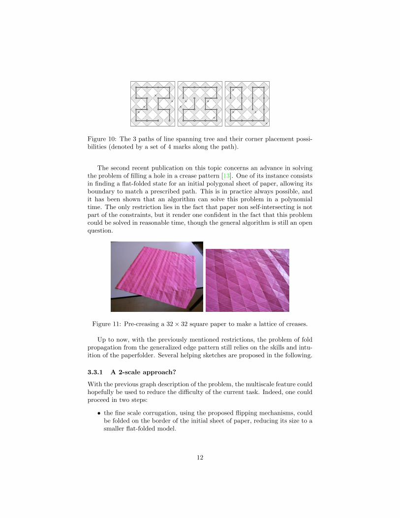
Figure 10: The 3 paths of line spanning tree and their corner placement possi-bilities (denoted by a set of 4 marks along the path).
The second recent publication on this topic concerns an advance in solvingthe problem of filling a hole in a crease pattern [13]. One of its instance consistsin finding a flat-folded state for an initial polygonal sheet of paper, allowing itsboundary to match a prescribed path. This is in practice always possible, andit has been shown that an algorithm can solve this problem in a polynomialtime. The only restriction lies in the fact that paper non self-intersecting is notpart of the constraints, but it render one confident in the fact that this problemcould be solved in reasonable time, though the general algorithm is still an openquestion.
Figure 11: Pre-creasing a 32× 32 square paper to make a lattice of creases.
Up to now, with the previously mentioned restrictions, the problem of foldpropagation from the generalized edge pattern still relies on the skills and intu-ition of the paperfolder. Several helping sketches are proposed in the following.
3.3.1 A 2-scale approach?
With the previous graph description of the problem, the multiscale feature couldhopefully be used to reduce the difficulty of the current task. Indeed, one couldproceed in two steps:
• the fine scale corrugation, using the proposed flipping mechanisms, couldbe folded on the border of the initial sheet of paper, reducing its size to asmaller flat-folded model.
12
• this last model could be considered as a sheet of its own, and its smallerperimeter could be mapped on the coarse scale corrugation, i.e. the graphpath.
If feasible, this approach has the advantage of separating the scales in this secondpart of the folding problem. The edge mapping is still an issue, but has to beperformed on a reduced-size problem (the coarse problem only).
The main issue relies on the scale separation. Indeed, dealing with discretegeometry, the microscale corrugation constrains the size of the coarse sheet ofpaper. A side of the flat-folded coarse sheet should provide two half-cornermechanisms and a particular number, say m, of pairs of edge mechanisms. Thecorresponding side length of the unfolded sheet is therefore a = 2× 3 + 4m. Fora square paper, this length should equals half of the optimal semiperimeter, soa = n2/2. With n even, one gets 2m = n2/4− 3. Nevertheless there is still anissue when starting from a square sheet of paper: since m should be an integer,n should not be a multiple of 4, i.e. n = 4k+ 2. In this case, m = 2k(k+ 1)− 1.This is feasible for n = 6 but not for n = 8. When n is a multiple of 4,this won’t apply, though an almost-square solution is possible: searching for arectangular sheet of size a1 × a2 with ai = 2 × 3 + 4mi, a1 + a2 = n2 and say,n = 4k, one gets m1 + m2 = 4k2 − 3 for which a solution is m1 = 2k2 − 2,m2 = 2k2 − 1 and a1 = n2/2 − 2, a2 = n2/2 + 2. Therefore, for n beinga multiple of 4, the scales are somehow entangled, and prevent the previoussolution procedure for a square coarse folded paper. Note also that the almost-square case is always slightly less complex that the square case since the meanthickness is t = a1a2/n
2 = n2/4− 4/n2 rather than t = a2/n2 = n2/4.Next section proposes a more direct solution to attempt the design from a
square sheet of paper, whose side can be a multiple of 4, as for the 8 × 8 pixelmatrix.
3.3.2 Onion layers strategy for compatible fold propagation
Going back to the initial edge mapping, the problem is at least two-fold: (i) theedge of the square paper should map the selected pattern, and (ii) the tortuosityof this path leads to a 2-scale corrugation on the edge of the paper, that haveto be propagated from the edge up to the center of the paper, while keeping thefolded state flat.
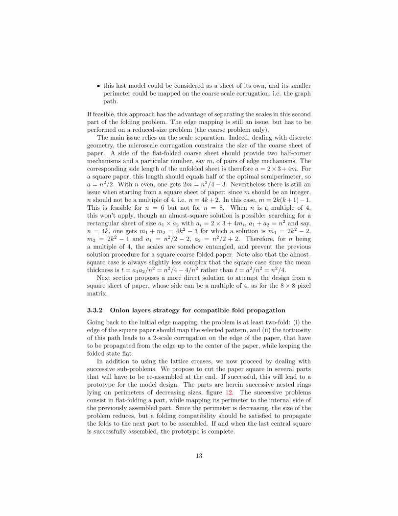
In addition to using the lattice creases, we now proceed by dealing withsuccessive sub-problems. We propose to cut the paper square in several partsthat will have to be re-assembled at the end. If successful, this will lead to aprototype for the model design. The parts are herein successive nested ringslying on perimeters of decreasing sizes, figure 12. The successive problemsconsist in flat-folding a part, while mapping its perimeter to the internal side ofthe previously assembled part. Since the perimeter is decreasing, the size of theproblem reduces, but a folding compatibility should be satisfied to propagatethe folds to the next part to be assembled. If and when the last central squareis successfully assembled, the prototype is complete.
13

Selection of the width of the strips is an interesting issue. The goal is two-fold: each strip should map on the previous edge pattern, and flat-foldabilityhas to be ensured. A thin strip would renders its flat-foldability easy, but donot solve enough foldability compatibility constraints, propagating too muchthe difficulty to the next inner strip, concentrating progressively the difficulty.Using a large strip allows to solve more progressively this issue but is moredifficult to map on the required edge pattern. There is therefore a compromiseto be found by choosing accordingly the onion layer width. For the 8× 8 pixelmatrix problem, a suited choice seems to be the one of figure 12 (right), witha width of 4. The problem is solved once the central 8 × 8 square has beensuccessfully mapped to the last perimeter.
Figure 12: Successive sub-problems with decreasing perimeters, for two choicesof width.
A successful prototype is reproduced in figure 13, allowing to conclude thatthe 8× 8 pixel matrix has the same bound on complexity as the chessboard.
Figure 13: An example of a complete prototype.
14

4 Conclusions
This article sets the pixel-matrix challenge for the point of view of folding op-timality, i.e. constraining the design of the given origami model by prescribingan initial paper sheet to be square. This appears to be a strong constraint thatdrives the complexity of the task. For a checkered n×n pattern design withouttransformable color-change (a static pattern), a bound on the semi-perimeter ofthe initial square of paper was s = n2, having been improved only for n largerthan 16. The pixel matrix adds the complex feature of a flipping mechanismallowing the local color-change independently on each board square. Thoughadding a somehow significant difficulty on the design (traduced here by a com-plex corner placement), a surprising result leads to the same complexity for the8× 8 design, as for the chessboard.
Concerning the design process, it has been exemplified that the brute force ofcomputers is still unable to tackle problems we wish to solve in flat geometricalorigami. The main issue remains the ability for the user to express the consid-ered problem in a suited form, and especially to split it in several well-chosenconsecutive sub-problems, some of them being susceptible to be computerized.In any case, a deeper analysis is required to reduce the problem size, and ex-press the problem within known scientific fields (such as graph theory). For thecurrent example, several analysis with increasing depths lead to a succession ofproblem size reductions. Then the computer can be helpful to provide informa-tion on the potential designs. Nevertheless, several steps still hold on intuitionand skills of human paperfolder to complete the design. In this sense, the com-puter may help, but cannot be substituted to the human for this task. Thisexample illustrates the fact that the dramatic announcement of predominanceof computer science on employability, when commenting the publication [18](there are also other predictions with significantly different fractions of autom-atizable jobs, for instance [8]), could certainly emphasizes the complementaryand gain to derive human-computer cooperation, though computers will lack tobe autonomous in solving problems that are ill-posed. The human-computerinterface will probably be a key issue, and problems need to be translated incomputer tackling world; in such a way we indeed need to transform our way ofworking [3, 37]. Such issues are also discussed about computer science educationand learning programs, pros and cons are discussed and currently debated onthe utility of early coding courses and/or on recasting traditional courses witha numeric culture orientation, as well as on addressing the issue of the tutoreducation.
References
[1] Z. Abel, J. Cantarella, E. D. Demaine, D. Eppstein, T. C. Hull, J. S. Ku,R. J. Lang, and T. Tachi. Rigid origami vertices: Conditions and forcingsets. preprint arXiv:1507.01644 [math.MG], 2015. arXiv:1507.01644.
15

[2] M. Bern and B. Hayes. The complexity of flat origami. In Proceedings ofthe Seventh Annual ACM-SIAM Symposium on Discrete Algorithms, pages175–183, Philadelphia, PA, USA, 1996. URL: http://doi.acm.org/10.1145/313852.313918, doi:10.1145/313852.313918.
[3] E. Brynjolfsson and A. McAfee. The Second Machine Age — Work,Progress, and Prosperity in a Time of Brilliant Technologies. W. W. Norton& Company, New York, 2014.
[4] P. Budai. Chequered patterns. http://www.budaiorigami.hu/en/
chequered. Accessed: 2015-08-29.
[5] S. Casey. Chessboard. In West Coast Origami Guild, volume 19, pages3–12, 1989.
[6] S. Chaiken and D. J. Kleitman. Matrix tree theorems. Journal ofCombinatorial Theory, Series A, 24(3):377–381, 1978. URL: http:
//www.sciencedirect.com/science/article/pii/0097316578900675,doi:10.1016/0097-3165(78)90067-5.
[7] S. Y. Chen. Checkerboard. In Annual OUSA Convention, pages 72–75,2001. URL: http://www.origami-usa.org/files/CheckerBoard.PDF.
[8] COE. Automation, digitalisation and employment – volume 1: im-pacts on job numbers, structure and location. Report summary, Con-seil d’Orientation pour l’Emploi – Employment Advisory Council, Jan-uary 2017. URL: http://www.coe.gouv.fr/IMG/pdf/310117_COE_-_
Summary_Report_Automation_and_Employment.pdf.
[9] V. Cumareshan. Pixel project at BOS 40th Anniversary Convention2007 (Cambridge). https://www.flickr.com/photos/childofsai/
1435876202, https://www.flickr.com/photos/childofsai/
1435874226/in/set-72157602149411581, September 6-9 2007. Ac-cessed: 2015-08-29.
[10] B. Dacorogna, P. Marcellini, and E. Paolini. Lipschitz-continuouslocal isometric immersions: Rigid maps and origami. Journalde Mathematiques Pures et Appliquees, 90(1):66–81, 2008. URL:http://www.sciencedirect.com/science/article/B6VMD-4RY8STC-4/
2/bac280f33fd27f6dba8a6cd4d1ada911, doi:DOI:10.1016/j.matpur.
2008.02.011.
[11] E. D. Demaine, M. L. Demaine, G. Konjevod, and R. J. Lang. Foldinga better checkerboard. In Y. Dong, D.-Z. Du, and O. Ibarra, editors,Algorithms and Computation, volume 5878 of Lecture Notes in ComputerScience, pages 1074–1083. Springer Berlin Heidelberg, 2009. doi:10.1007/978-3-642-10631-6_108.
16
[12] E. D. Demaine, S. P. Fekete, and R. J. Lang. Circle packing for origamidesign is hard. preprint arXiv:1008.1224 [cs.CG], 2010. arXiv:1507.
01644.
[13] E. D. Demaine and J. S. Ku. Filling a hole in a crease pattern: Isometricmapping from prescribed boundary folding. CoRR, abs/1410.6520, 2014.arXiv:1410.6520.
[14] E. D. Demaine and J. O’Rourke. Geometric Folding Algorithms: Linkages,Origami, Polyhedra. Cambridge University Press, New York, NY, USA,2008.
[15] M. Desjarlais and R. Molina. Counting spanning trees in grid graphs.In Congressus Numerantium – 31st Southeastern international conference;Combinatorics, graph theory and computing, volume 145, pages 177–185,2000.
[16] D. Dureisseix. Chessboard. British Origami, 201:20–24, 2000. URL: https://hal.archives-ouvertes.fr/hal-01380815.
[17] T. A. Evans, R. J. Lang, S. P. Magleby, and L. L. Howell. Rigidly foldableorigami gadgets and tessellations. Royal Society Open Science, 2:150067,2015. URL: http://www.researchgate.net/publication/281845234,doi:10.1098/rsos.150067.
[18] C. B. Frey and M. A. Osborne. The future of employment: how susceptibleare jobs to computerisation. Retrieved September, 7:2013, 2013.
[19] E. Gjerde. Origami Tesselations – Awe-Inspiring Geometric Designs. A KPeters, Ltd.
[20] S. Grabarchuk. The origami checkerboard puzzle. http:
//www.ageofpuzzles.com/Puzzles/OrigamiCheckerboardPuzzle/
OrigamiCheckerboardPuzzle.htm, 2008. Accessed: 2016-10-12.
[21] G. Hollebeke. Echiquier. Le Pli, 107-108:8–13, 2007. In French.
[22] T. Hull. The combinatorics of flat folds: a survey. In T. Hull, editor,Origami 3 – Proceedings of the Third International Meeting of OrigamiScience, Mathematics, and Education, pages 29–37. A K Peters, 2002.Also available on arXiv:1307.1065 [math.MG]. URL: http://arxiv.
org/abs/1307.1065v1.
[23] Thomas Hull. Project Origami – Activities for Exploring Mathematics.CRC Press, 2nd edition, 2013.
[24] M. Hulme. Chess sets. In BOS Booklet, number 7. BOS, 1985.
[25] M. Hulme. Pixel unit. In Yamaguchi Makoto, editor, Origami TanteidanMagazine, volume 18, pages 171–172, Tokyo, Japan, 2012. Japan OrigamiAcademic Society (JOAS), Nishikawa Seiji. 18th convention booklet.
17

[26] J. Justin. Towards a mathematical theory of origami. In K. Miura et al,editor, Origami Science and Art: Proceedings of the Second InternationalMeeting of Origami and Scientific Origami, pages 15–29, 1997.
[27] G. Kirchhoff. Uber die auflosung der gleichungen, auf welche man beider untersuchung der linearen verteilung galvanischer strome gefuhrt wird.Poggendorfs Annalen fur der Physik und der Chemie, 72:497–508, 1847.English translation by J. B. O’Toole, On the solution of the equationsobtained from the investigation of the linear distribution of galvanic cur-rents, IRE Trans. on Circuit Theory, CT-5:4-7, 1958. doi:10.1002/andp.18471481202.
[28] M. Kirschenbaum. Chessboard. The Paper, 61:24–30, 1998.
[29] D. E. Knuth. The Stanford GraphBase, A platform for combinatorial com-puting. ACM Press, 1993.
[30] G. Konjevod. Integer programming models for flat origami. In R. J.Lang, editor, Origami 4 – Fourth International Meeting of Origami Sci-ence, Mathematics and Education, pages 207–216. A K Peters, 2009.
[31] R. J. Lang. TreeMaker. http://www.langorigami.com/science/
computational/treemaker/treemaker.php. Accessed: 2015-08-29.
[32] R. J. Lang. A computational algorithm for origami design. In Computa-tional Geometry: 12th Annual ACM Symposium, pages 98–105, Philadel-phia, Pennsylvania, 1996.
[33] D. Mitchell. Paperfolding Puzzles. Kendal, United Kingdom, 2nd edition,2011.
[34] J. Montroll. Origami inside-out. Dover, 1993.
[35] OEIS Foundation Inc. The on-line encyclopedia of integer sequences. Num-ber of spanning trees in n x n grid. http://oeis.org/A007341, 2011.Accessed: 2015-08-29.
[36] SGB. The Stanford GraphBase. http://www3.cs.stonybrook.edu/
~algorith/implement/graphbase/implement.shtml. Accessed: 2015-08-29.
[37] M. Shanahan. The Technological Singularity. MIT Press, 2015.
[38] R. Shrock and F. Y. Wu. Spanning trees on graphs and latticesin d dimensions. Journal of Physics A: Mathematical and Gen-eral, 33:3881–3902, 2000. Also available on arXiv:cond-mat/0004341
[cond-mat.stat-mech]. doi:10.1088/0305-4470/33/21/303.
[39] N. J. A. Sloane and S. Plouffe. The Encyclopedia of Integer Sequences.Academic Press, 1995.
18

[40] T. Tachi. Rigid Origami Simulator. http://www.tsg.ne.jp/TT/software.Accessed: 2015-08-29.
[41] T. Tachi. Simulation of rigid origami. In Fourth International Conferenceon Origami in Science, Mathematics, and Education (4OSME), pages 175–187, 2009.
[42] H. Tahir. Origami dot-matrix. https://www.flickr.com/photos/
31897685@N06/16726050538. Accessed: 2015-08-29.
[43] W. T. Tutte. Graph Theory. Cambridge University Press, 2001.
[44] Z. Xiao, R. Bosch, C. S. Kaplan, and R. J. Lang. Modular origami halfton-ing: Theme and variations. In McKenna D. K. Delp, C. S. Kaplan andR. Sarhangi, editors, Proceedings of Bridges 2015: Mathematics, Music,Art, Architecture, Culture, pages 61–68, Phoenix, Arizona, 2015. Tessella-tions Publishing. Available online at http://archive.bridgesmathart.
org/2015/bridges2015-61.html.
19

A Some pixel matrix designs
For a n× n static checkerboard, the optimality argument (satisfied for n < 16)states that the smallest square of paper has a semiperimeter s = n2 for an evenn. The following examples illustrate the feasibility of the same bound for thepixel matrix.
A.1 The 2× 2 pixel matrix
The 2 × 2 pixel matrix is obtained with a single design from a 2 × 2 squareof paper, following figure 14. It is nevertheless somehow disappointing sincethe lack of wasted paper does not allow to provide additional underlying paperwhen folding the corners. This is an edge effect that can be discarded but withthe price to use a sub-optimal 4× 4 paper (whose design is left to the reader).
A 2× 2 checkered board in [11] uses a 3× 3 paper, but cannot flip its coloreasily. The design of appendix B.1 can, but still have an edge effect defect of1 board square. Therefore, it is unlikely that a design without such edge effectcan be folded with a square paper smaller than 4× 4.
Figure 14: The optimal 2× 2 pixel matrix, from a 2× 2 square of paper.
A.2 4× 4 pixel matrix
The 4× 4 pixel matrix cannot be obtained with a square whose semiperimenteris s = 42 = 16, i.e. with a 8×8 square paper. There are several possible designsfrom a 10× 10 paper; one is depicted in figure 15.
20
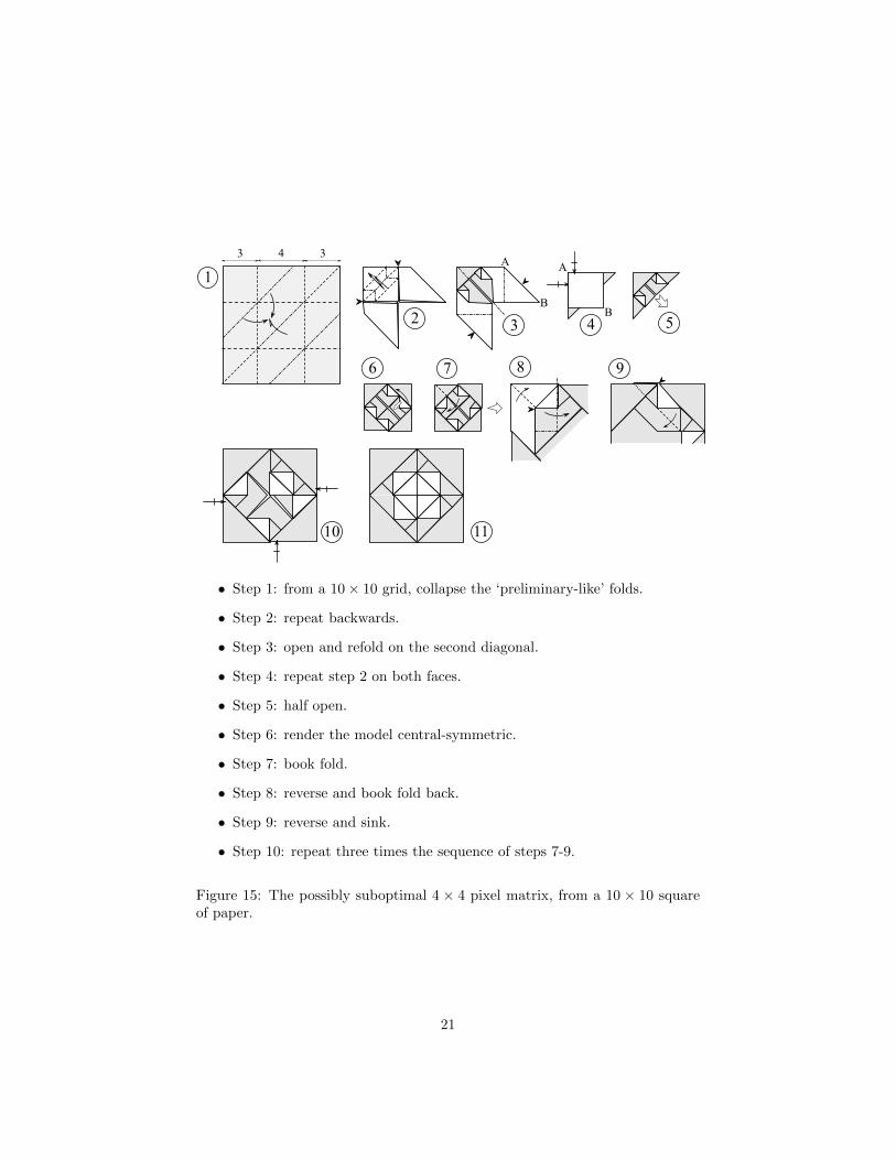
• Step 1: from a 10× 10 grid, collapse the ‘preliminary-like’ folds.
• Step 2: repeat backwards.
• Step 3: open and refold on the second diagonal.
• Step 4: repeat step 2 on both faces.
• Step 5: half open.
• Step 6: render the model central-symmetric.
• Step 7: book fold.
• Step 8: reverse and book fold back.
• Step 9: reverse and sink.
• Step 10: repeat three times the sequence of steps 7-9.
Figure 15: The possibly suboptimal 4 × 4 pixel matrix, from a 10 × 10 squareof paper.
21

A.3 6× 6 pixel matrix
There are solutions for a 6× 6 pixel matrix form a seminperimeter s = 62 = 36,i.e. with a 18×18 square of paper. A design with a central symmetry is depictedin figure 5 and is a solution of the previous sub-problem of finding a path in acoarse graph. This step can be seen as a macroscopic problem while the detailedflipping mechanism folding for color-changing is a microscopic corrugation alongthe paper edge.
Finding the complete folding sequence can then be studied by at least twomeans:
• propagating the folds from the edge once mapped on the targeted finalfolding state (the edge diagram);
• using a two-scale approach.
This last case may well be available, at least for even n of the form n = 2(2k−1)with an integer k (so that n = 2, 6, 10, 14 . . .). Indeed, for this case, the flippingmechanisms can be folded flap to a ‘coarse’ square configuration of edge lengthc = (n/2)2+1. Then one can search for designing a folding sequence of this c×csquare as a whole, mapping its ‘coarse’ perimeter on a dedicated edge patternbuilt from the previous spanning tree (figure 16). If this pseudo c × c squarecan be folded this way, then the problem is fully separated on the two scales.Whether this is a general property for any n or not is still an open question.
For the k = 2, n = 6, s/2 = 18, c = 10 case, the ‘coarse’ problem is not toocomplex, using the central symmetry of the design, but cose not fully statisfyto the lattice origami principle. Indeed one issue is a shift of value 2 in figure 16(step 3) leading to a ‘shearing’ of the square. A twist fold can be made as forsome tesselation designs [19, 23], than involves an angle α with tanα = 2/6 =1/3 that cannot lie on the (0, 45°, 90°) c× c regular grid.
Figure 17 provides a folding sequence. Note that for this coarse model,there is some paper self-intersection in the vicinity of point A at step 2e, whenrepeating the sequence on the half-bottom part (to avoid this, the book fold ofstep 2e is mandatory). This cannot be solved at the only coarse scale, and ispostponed to the complete pixel-matrix folding sequence, leading to concludethat the two scales may well be not fully separable.
Figure 16: A path location for the generalized edge pattern of the 6 × 6 pixel-matrix problem, and the corresponding coarse edge location of length 4c = 40supporting the fine corrugation.
22

• Step 1: twist fold.
• Step 2: fold behind. Turn the model.
• Step 2a: complex pleat, pivoting right part.
• Step 2b: unfold and swivel fold.
• Step 2c: book fold. Rever inside flap outside.
• Step 2d: squash fold.
• Step 2e: fold the flap to avoid subsequent interference. Repeat previoussteps at the bottom.
Figure 17: The coarse folding of a 10× 10 square to a 6× 6 pattern intended tobe the coarse pixel-matrix.
23

B Some static checkered boards
Note for completion, that there is a series of origami puzzles based on checkeredpatterns, willing to obtain the smallest number of folds [20, 33] whereas we areherein interested in the smaller waste of paper. For a n×n static checkerboard,the optimality argument (satisfied for n < 16) states that the smallest square ofpaper has a semiperimeter s = n2 for an even n, and s = n2 − 1 for an odd n.Some designs are given in the following sections. One can note that there is aconstructive proof of the previous bounds for s; indeed, a recursive constructionis given in the last following sections.
B.1 2× 2 checkered board
As previously mentioned, the 2× 2 case can be folded from a sub-optimal 3× 3paper [16], figure 18.
Figure 18: The suboptimal 2× 2 checkerboard, from a 3× 3 square of paper.
B.2 3× 3 checkered board
Following the technique of the edge diagram, the 3×3 checkered board requiresa semiperimeter of 8, so a 4 × 4 square sheet of paper. There are 3 possiblecorner placements, one of them leading to the folding sequence of figure 19.
• Step 1: from a 4× 4 grid, fold along the crease pattern.
• Step 2: two swivel folds.
• Step 3: color change.
Figure 19: The optimal 3× 3 static checkerboard, from a 4× 4 square of paper.
It is also disappointing since the lack of wasted paper does not allow toprovide additional underlying paper when folding the corners. This is an edge
24

effect that can be discarded but with the price to use a sub-optimal 5× 5 paper[16], figure 20.
Figure 20: The sub-optimal 3 × 3 static checkerboard, from a 5 × 5 square ofpaper.
B.3 4× 4 checkered board
The optimal case here corresponds to a 8 × 8 square paper. This is the firstcheckerboard that allows to avoid edge effects while being optimal. A compactfolding sequence of the original design of Max Hulme [24] is depicted in figure 21.
• Step 1: collapse with preliminary folds.
• Step 2: open one layer.
• Step 3: fold back.
• Step 4: repeat three times (care of the symmetry of the model).
• Steps 5 and 6: bookfolds for color change.
Figure 21: The optimal 4× 4 static checkerboard, from a 8× 8 square of paper.
25

B.4 5× 5 checkered board
The optimal case corresponds to a 12 × 12 square paper. figure 22 proposes asolution.
Finally, a geometric picture (with the checker edges 32 + 42 = 52 and theiroptimal square edges 4 + 8 = 12) allows to illustrate the Pythagorean theorem,together with the puzzle-like proof of Da Vinci, figure 23.
26

• Step 1: fold the 12× 12 paper. Turn the model.
• Step 2: distorted preliminary-like base.
• Step 3: fold the flap.
• Step 4: 2 coupled squashes.
• Step 5: squash and crimp on the left; swivel on the right.
• Step 6: swivel; repeat steps 3-6.
• Step 7: flip for color change. Turn the model.
• Step 8: fold the flap.
• Step 9: fold.
• Step 10: flip for color change; repeat steps 8-10. Unfold the back facealong main diagonal.
• Step 11: 2 couples swivels.
• Step 12: flip for color change.
Figure 22: The optimal 5 × 5 static checkerboard, from a 12 × 12 square ofpaper.
27

Figure 23: The Pythagorean theorem with its proof-without-word of Da Vinci.
28

B.5 8× 8 chessboard
The following model has been published in [16] and produces a 8×8 chessboardfrom a 32 × 32 square of paper. It is therefore expected to be optimal. Thefolding sequence of figures 24 and 25 is:
• Step 1: pre-crease the 1/16th. Waterbomb-base folds.
• Step 2: rotate to lock. Turn over.
• Step 3: bring edges again toward center.
• Step 4: sink.
• Step 5: book fold. Repeat steps 4-5.
• Step 6: petal fold. Repeat.
• Step 7-8: fold flaps. Here is a 2× 2 pattern.
• Step 9: squash and swivel together.
• Step 10: petal fold (note the dissymmetry of the fold).
• Step 11: open sink on the left. Reverse fold on the bottom.
• Step 12: open sink again on the left. Same fold as in step 9 on the right.
• Step 13: squash-swivel on the left. Same fold as in step 10 on the right.
• Step 14: same fold as in step 9.
• Step 15: same fold as in step 10.
• Step 16: color change. Repeat steps 8-16 according to symmetries.
• Step 17: here is now a 4× 4 pattern. Re-fold wider.
• Step 18: color change. Repeat steps 17-18 everywhere needed.
29

Figure 24: The optimal 8× 8 static chessboard, from a 32× 32 square of paper.
30

Figure 25: The optimal 8× 8 static chessboard, from a 32× 32 square of paper.Continued.
31

B.6 Generic construction of an n× n checkerboard
A generic folding sequence can be built for a general n × n checkerboard. Thedesign is not the most elegant, but it can be extended to any number n ≥ 5.The folding sequence relies of a strip circulating on the folded model than leadsto a ‘dendritic-like’ edge pattern, depicted in figure 26 for n = 8 and n = 7cases.
Figure 26: Edge diagrams for n = 8 and n = 7 (half top parts only).
The n = 2p even case has two symmetries with respect to the diagonals ofthe board. The sequence is the repetition of a generic sub-sequence, which isdescribed in figure 27.
The odd case is more difficult than the even case since it possess less sym-metries, and is described herein. The sequence is also the repetition of a genericsub-sequence, except for the last stage that leads to complete a n = 5 halfcheckerboard which is of particular design as a kind of edge effect. This special5× 5 is depicted in figure 28, and the constructive proof in figure 29.
Following this process, a 11× 11 checkerboard has been folded that is prob-ably the largest optimal checkerboard that has been effectively folded. It isphotographed in figures 30 and 31.
32

• Step 1: after the pre-crease of a n× n grid, with all diagonals pre-creasedas well, make p− 2 pleats along the diagonal direction.
• Step 2: book fold back.
• Step 3: squash and book folds.
• Step 4: swivel fold.
• Step 5: a complex squash and swivel coupled fold.
• Step 6: flip on the right and make p − 2 inside reverse folds to make thesame number of pleats.
• Step 7: outside reverse fold.
• Step 8: book fold.
• Step 9: make p− 3 pleats.
• Step 10: book fold back (this step is similar to step 2). Repeat by recursionfrom step 3, replacing p by p− 1.
Figure 27: The generic folding sub-sequence for the optimal n×n static checker-bord, for n even (only one fourth of the square is depicted due to symmetries).
33

• Step 1: book fold one-third of the 12× 12 square.
• Step 1a: make a pleat and a squash fold.
• Step 1b: squash and unfold.
• Step 2: book fold, and flip.
• Step 3: make two underlying pleats.
• Step 4: preliminary fold, and two swivel folds.
• Step 5: half fold and flip.
• Step 6: fold back with a squash and a pleat.
• Step 7: book fold.
• Step 8: two swivel folds.
• Step 9: flips.
• Step 10: inside reverse fold, and book fold back.
• Step 11: flip and repeat on the bottom for the full 5× 5 design.
Figure 28: Another folding sequence of the optimal 5×5 static chessboard, froma 12× 12 square of paper.
34

• Step 1: after the pre-crease of a n× n grid, with all diagonals pre-creasedas well, make p− 2 pleats along the diagonal direction.
• Step 2: book fold back.
• Step 3: squash and book fold, with one pleat at the back.
• Step 4: a complex squash and swivel coupled fold.
• Step 5: flip on the right and book fold back on the left.
• Step 6: one double inside reverse fold on the right to make a pleat, andrepeat step 3 on the left.
• Step 7: repeat step 4 on the left.
• Step 8: flip on the left.
• Step 9: outside reverse folds. Return.
• Step 10: book fold.
• Step 11: the obtained result is similar to step 1. The entire folding sub-sequence 1-11 can now be repeated recursively (replacing p by p− 1, andswitching points A and B), until step 3 of figure 28 is obtained, leadingto the last stages of this figure.
Figure 29: The generic folding sub-sequence for the optimal n×n static checker-bord, for n odd (only one half of the square is depicted due to symmetry).
35
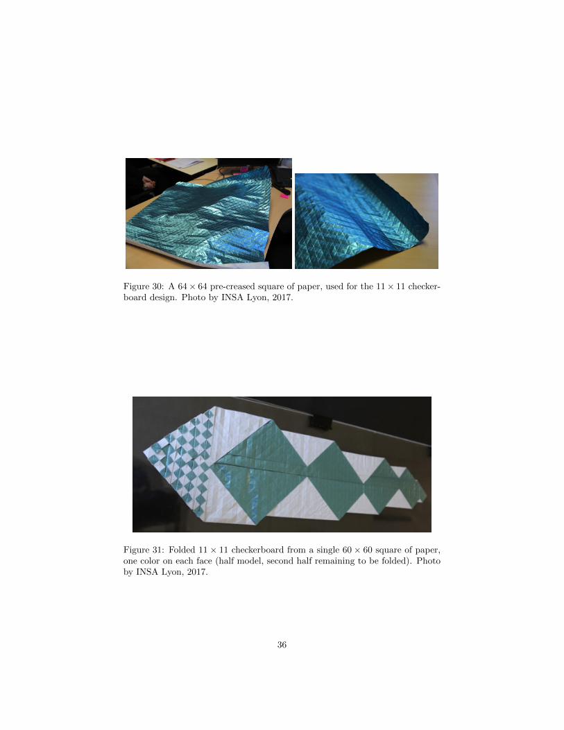
Figure 30: A 64× 64 pre-creased square of paper, used for the 11× 11 checker-board design. Photo by INSA Lyon, 2017.
Figure 31: Folded 11× 11 checkerboard from a single 60× 60 square of paper,one color on each face (half model, second half remaining to be folded). Photoby INSA Lyon, 2017.
36