an experimental study on levee failure caused by seepage
TRANSCRIPT

Memoirs of the Faculty of Engineering, Okayama University, Vol. 22, March 1988
An Experimental Study on Levee Failure Causedby Seepage and Preventive Measures
Iichiro KOHNO* • Makoto NISHIGAKI*. and Yuji TAKESHITA*
(Received January 3D, 1988)
SYNOPSIS
There are two classifications of the mechanism of levee
progressive failure.
failure caused by floods;
The
local seepage failure and
fundamental causes of levee
failure produced by piping and erosion were studied and the
safety of river levees during floods evaluated in terms of
soil mechanics.
The critical hydraulic gradient and the process of
progressive failure were obtained from one- and two
dimensional model experiments for piping and erosion.
Problems inherent in and preventive measures against
levee failure are discussed. In particular, effects of the
Tsukinowa method,
fighting method,
the most representative Japanese flood
were studied experimentally and
improvements proposed.
* Department of Civil Engineering
45
46 Iichiro KOHNO, Makoto NISHIGAKI and Yuji TAKESHITA
1.INTRODUCTION
During flooding, river levees may be destroyed by seepage and
piping. The mechanisms of levee failure caused during floods can be
classified (1) as local seepage or sliding failure in which the water
pressure or seepage forces exceed the resisting forces of the levee,
and (2) progressive failure in which internal erosion within the levee
is enlarged by seepage flow. To make clear the mechanisms of river
levee failure caused by seepage and leakage during floods, we used a
soil mechanics approach to develop a method of levee failure predic
tion. Existing prevention methods are evaluated, and suggestions for
improving them made.
Several studies have been done in order to clarify the mechanisms
of river levee failure.[1]-[5] Our study reported here
includes,discussion of the progressive erosion and failure of a levee
due to piping based on experimental and theoretical results.
In section 2, the fundamental types and mechanisms of seepage
failure are classified as 1) failure that takes place when seepage
forces exceed the resistance forces of a levee, and 2) failure
caused by progressive erosion.
In section 3, one- and two-dimensional sand model experiments on
erosion are described that show the mechanism that operates during
progressive failure of a levee owing to seepage,
Lastly, in section 4 existing preventative measures against levee
failure are evaluated based on the results reported here, and new
preventive measures are proposed.
2. LEVEE FAILURE OWING TO SEEPAGE OR LEAKAGE
2.1 Shearing Failure Produced by Water Pressure
When there is a sudden rise in the water level in a river, or
along an impervious slope on the riverside of a levee, shearing fail
ure of that levee is easily produced by water pressure, especially in
levees built on soft foundations. The most dangerous stage is when the
water level has reached the crown.
2.2 Failure Caused by Increasing Pore Pressure and Water Content
With an increase in pore pressure the shear strength decreases
Levee Failure Caused by Seepage 47
because the effective stress is lessened. In the unsaturated condi-
cohesion
tion, the effective stress increases because of capillary suction,
which is a negative pore pressure. But, with increasing water content
suction forces are decreased, and the shear stress becomes small. It
is well documented that as the water content increases,
decreases.[6]
The resisting forces of a levee against water pressure, seepage
and erosion become weak because of the above process and the degree of
danger of levee failure increases markedly. Failure, which often
appears as sliding failure on the levee's slope, usually has been
studied by the circular slip surface method. Recently, evaluations of
levee safety and failure have been improved by the use of finite
element analysis.
2.3 Slope Failure of a Levee Caused by Seepage
The seepage force (j) is defined as
j r w * i ..•..... (1)
in which
and
i is the hydraulic gradient,
r w is the unit weight of the water.
Seepage force is applied to the unit volume of the soil mass
because of seepage flow. This force works in the same direction as the
seepage flow in an isotropic aquifer. For convenience, seepage force
often is treated as body force in finite element analysis. This treat
ment is the same as for gravity; but, assuming that a large soil mass
is a rigid body and that a balance of forces is considered in the
circular slip surface method, it is more convenient that seepage force
be treated as the water pressure present at each boundary.[7],[8]
While the water level in a river remains high, the wetting front
rapidly progresses into the levee. Until water infiltrates the levee;
that is, until there is no seepage from its slope, the levee generally
can be considered more stable than if there were an actual leak. This
is important in the design 'of a levee.
2.4 Failure Caused by Erosion
Local shear failure occurs at locations where the seepage force

48 Iichiro KOHNO. Makoto NISHIGAKI and Yuji TAKESHITA
is high and the confining force or strength of the soil is low, e.g.;
on the surface of the slope or a channel. In particular, seepage
water accumulates in channels in the soil, and the seepage force
becomes very strong because the hydraulic gradient becomes high. As a
result, because of local failure the channel in the soil is enlarged
and extended into the heart of the levee or is spread two- or three
dimensionally causing general failure of the levee.
The types of progressive failure are
(1) Hydraulic Fracturing
If the surface of the levee is exposed to high water pressure,
cracks will appear at weak and highly permeable areas of the levee
body. These cracks eventually cut deeply into the levee and become
wide erosion channels. This phenomenon, called hydraulic fracturing,
is dependent on heterogeneous permeability, levee strength, deforma
tion characteristics and the existence of initial small cracks, It is
very difficult to evaluate quantitatively as well as to predict the
behavior of hydraulic fracturing.
Hydraulic fracturing usually progresses from the upstream to the
downstream side, a phenomenon opposite to regular piping. Hydraulic
fracturing has been reported to be the cause of failures of earthen
dams; e.g., the Teton Dam in the U.S.A .. The effects of sUch
fracturing are readily observable in laboratory sand model
experiments.[9]
(2) Piping and Roofing
The phenomenon in which soil is washed away by seepage forces"and
the channel advance from downstream to upstream in the form of a pipe
is, called piping. Channels also may develop two-dimensionally or
spherically. There are many kinds of piping owing to various seepage
characteristics and soil strength distributions.
Wheneyer rigid structural elements are placed over a semirigid or
erodible foundation, seepage which causes movement of particles from
the foundation generally is called 'roofing'.
(3) Soil erosion caused by discontinuity of the soil structure
When water flows through a fine soil layer to a coarse soil
region, as in a blind drainage conduit; the fine-grained soil is
washed into the pores of the coarse layer by the high seepage fOrce.
Asa result, channels or loose regions appear along the boundary
between the two regions. This phenomenon produces a very strong
possibility of piping occurring. Therefore, care must be taken in
levee design to ensure that there is no great difference in soil

LeVl'e Failure Caused by Seepage 49
particle diameter (within reasonable limits) at soil layer boundaries
(10),[11). When a fine soil levee is constructed on a highly permeable
coarse layer, there is danger of failure conditions being produced.
3. PROGRESSIVE FAILURES OF RIVER LEVEES CAUSED BY SOIL EROSION
3.1 One-Dimensional Model Experiment of Progressive Erosion
The equation for the critical hydraulic gradient suggested by
Terzaghi generally has been used to evaluate the safety of piping,
boiling and quick sand. His equation is applicable only to cases in
which no shear stress exists and there is only vertical seepage
flow in sand. Also, deformation of soil is not considered. These
deficiencies have been shown experimentally in many reports.[12]
[19] Because, at present, there is no standard method for estab-
lishing the size of a specimen, it is difficult to establish the
relation that corresponds to the field. Similarly, much research on
the critical hydraulic gradient has been published [16],[19],[20],
but it is difficult to obtain a clear index with which to quantita
tively evaluate piping and boiling. Therefore, we did experiments,
which used two kinds of soil, sand and granite, (grain size distribu
tion is shown in Fig. 4), for various specimen sizes. The-2
permeability coefficient of the sand was 2.31x10 cm/s and of the-3
granite soil 1.50x10 cm/s.
(a) Experimental Method
a constant rate to increase the
outflow from the specimen sudden-
llwor.1ll:aI yah... fA TInCIghi
Sand )G<onito ....
.. GrGnU. sol( .. :-..go 001... <I_I
o Sand(.:-..go ...... ·<1_1
Colc....ted .lngIo~
....0' ..... ,....
Fig.1 Relation of the diameterof the open region to thecritical hydraulic gradient.
(sample length 12cm)
oIio S.O
~u
;"15.0
I~ 10.01----
i
mold with an
19.4 cm and
was used. A
open region
top of this
head at the
gradient. The critical
gradient (i c ) was the
which the volume of the
hydraulic
hydraulic
point at
A cylindrical
inside diameter of
and a length of 36 cm
filter which had an
was placed at the
mold. The pressure
bottom of the mold was raised at
ly became large. The relation of
50 Iichiro KOHNO, Makoto NISHIGAKI and Yuji TAKESHITA
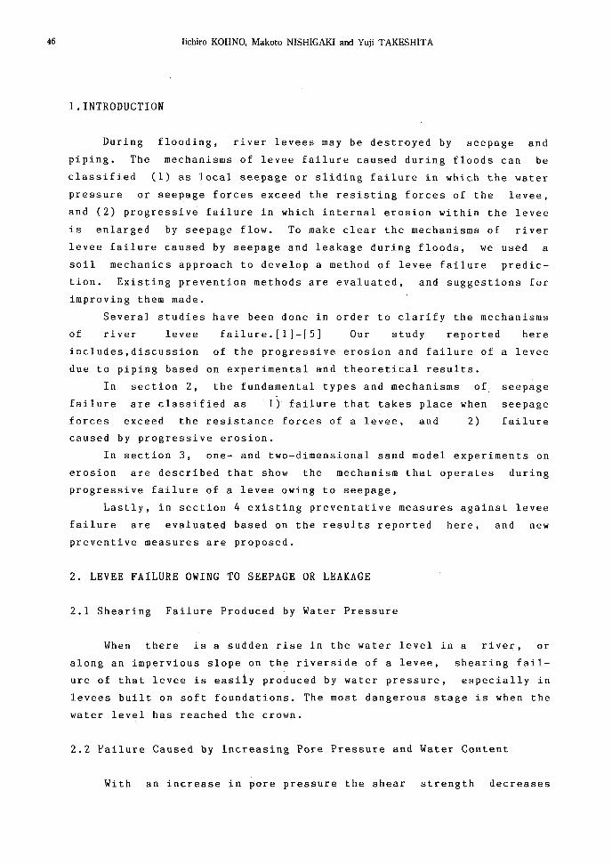
Fig. 2
the diameter of the open region to the
critical hydraulic gradient is shown in
Fig.l for a specimen' 12 cm long, and
is compared to theoretical values by
Ter zaghi I s method. For sand, i c has a
constant value that is independent of
the diameter of the open region, but for
granite soil i c is reduced as the
diameter of the open region increases.
The relation of the critical hydraulic
gradient to specimen length when the
diameter of the open region was 8cm is
shown in Fig. 2. Clearly, the length of
the experimental specimen must be more
~ 1Qol=:==~==~==~;:""--I
c~ 8.01--=,""",~~eCII
~ 6.°rn;~~~~,#-:;:;~:;---j"5o~ 4.0.s:
~ 2.01----f1---t---+----I8 1M,
Q.00!:-----:12=-----::!24i:----::!3'=-6__oJ
Length of specimen (em)
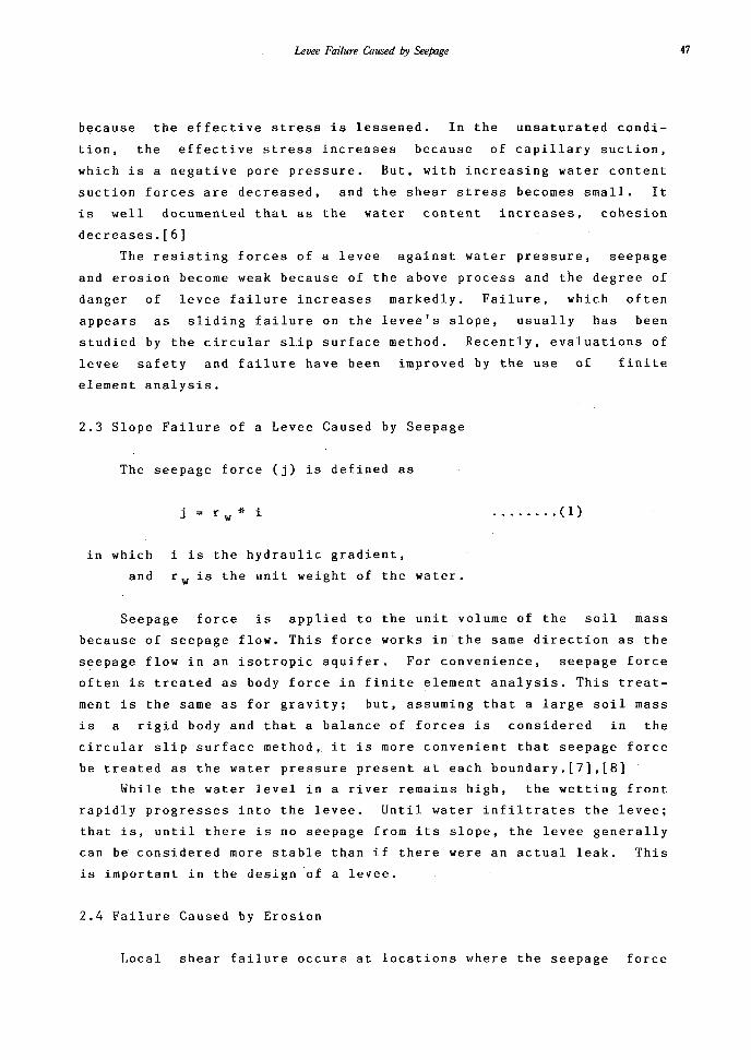
Relation of the lengthof the sample to thecritical hydraulicgradient.
SandGranlle Soli
Relation of the void ratioto the critical hydraulicgradient.
~ l.ol==r;;;::-;;::::::;;:::;-:--;-.....,..:-=--~~=l
lio.o'--~-_.....,..,...----~---'---'0.5
! 4.ol-~LJ'iiK6:~
j. 3.OH-~~I~~~i51 2.O'1--t-,L--~,-,<9';'(J..!!
less
void ratio to the critical hydraulic
gradient as shown in Fig.3.
than 12cm because at a length
than 12cm experimental results were
effected by the open region, and the
specimen usually failed owing to the
seepage force at the critical hydraulic
gradient value.
To study changes in the shearing
resistance produced by the void ratio,
we ran experiments at various void
rates and obtained the relation of the Fig. 3
(b) Considerations of the
experimental results
For the vertical!
one-dimensional experi- Iment for piping, the
critical hydraulic gra
dient (i c ) can be expres
sed by the equilibrium
condition of the sub
merged unit weight of the
soil and the shearing
resistance;
......... rei" C".
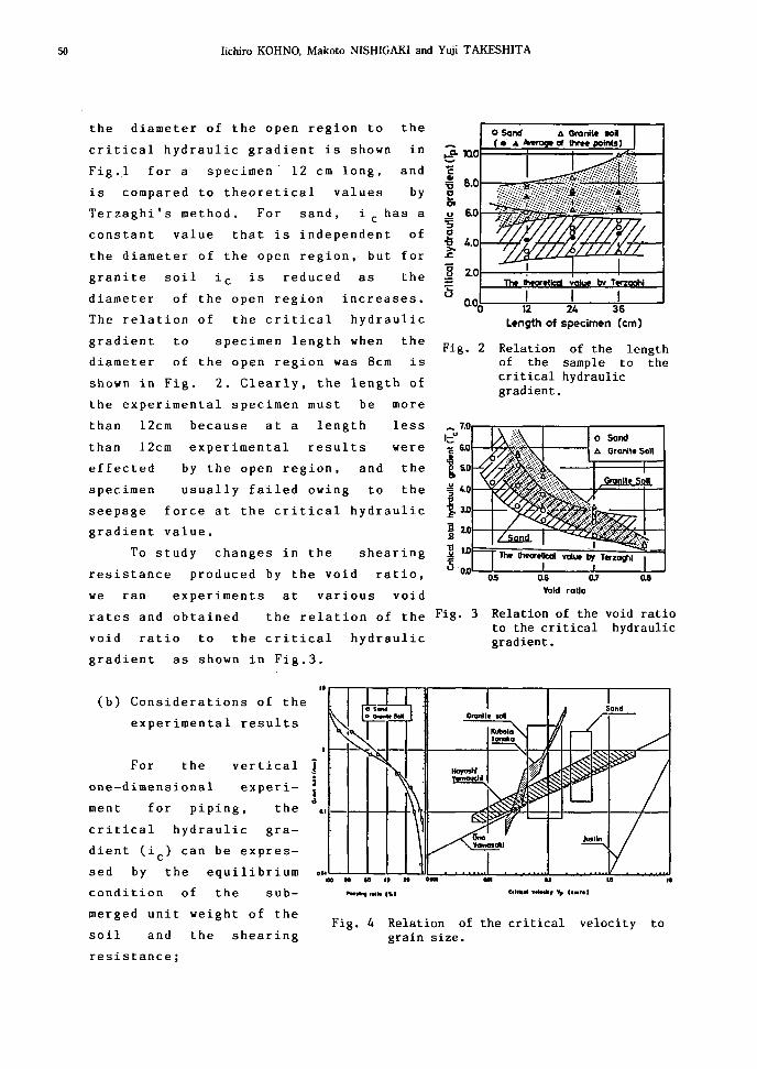
Fig. 4 Relation of the critical velocity tograin size.

Levee Failure Caused by Seepage 51
. . • •. (2)
in which
r su~
rwc
r
e
and Gs
is the submerged unit weight of the soil,
is the unit weight of the water,
is the cohesion of the soil,
is the radius of the failure region,
is the void ratio,
is the specific gravity.
When Eq. (2) is compared with experimental results for which
the value of the cohesion obtained from the shear test ( csO for
river sand and c s 10 gf/cm 2 for granite soil) was used (Fig. 1), the
calculated values for i c agree well with the experimental values
found for granite soil.
Previous results obtained for the relation of grain size to
critical velocity are shown in Fig. 4. Piping occurred with liquefac
tion of grains when the grain size was less than D 25 - D35 as
reported by Ohno [20] ( D 25 is the grain size at which 25%, by
weight, of the grains are smaller; similarly for D 35 , QSO' etc.). This
figute shows that experimentally it was possible to move the fine
grained soil,which explains why boiling may appear intermittently
under conditions in which the quick sand phenomenon dose not.
3.2 Two-Dimensional Model Experiments of the Progressive Erosion
Horizontal and vertical two-dimensional experiments, used the
same river sand and granite soil utilized in the one-dimensional
experiment done to study the mechanics of soil erosion caused by
seepage. The form of failure and the distribution of pore water pres
sures were measured, the mechanisms of failure being determined from
models made of the leakage from the levee itself or from its
foundation.
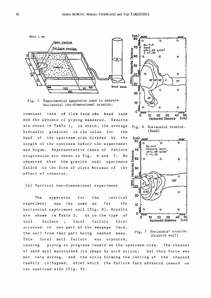
(a) Horizontal two-dimensional experiment
The apparatus in Fig. 5
appearance of the seepage face.
cm thick with a 10 cm open
shows that piping grows after the
It was made of intensified glass 2
zone on one vertical side of the
apparatus. The pressure head on the upstream side was increased at a
~2 Iichiro KOHNO, Makoto NISHIGAKI and Yuji TAKESHITA
Unit em
constant rate of flow from the head tank
o
o
o
o
o
o
15"
o1'30"
10 20 30 40 50Horizontal Distance (em)
o
0
0 10 20 30 40 50Horizontal Distance (em)
Fig. 6 Horizontal erosion.(Sand)
(em)80
0 0 0No.4-3Granite soilpd~1.48 gfern'i ~1.30
0 0 0
the
first
Results
vertical
for
the
failure
in which, the average
for
local
was the same as
apparatus
failure
The
(b) Vertical two-dimensional experiment
Fig. 5 Experimental apparatus used to measurehorizontal two-dimensional erosion.
o en re ion
experiment
soil
and the advance of piping measured.
are shown in Table 1,
horizontal experiment soil (Fig. 8). Results
are shown in Table 2. As to the type of
hydraulic gradient is the value for the
head of the upstream side divided by the
length of the specimen before the experiment
was begun. Representative cases of failure
progression are shown in Fig. 6 and 7. We
observed that the granite soil specimens
failed in the form of pipes because of the
effect of cohesion.
was repeated,
occurred in one part of the seepage
the soil from that part being washed
This local soil failure
face,
away. Fig. 7 Horizontal erosion.(Granite soil)
causing piping to progress inward on the upstream side. The channel
of sand soil maintained its shape by arch action, but this force was
not very strong, and the soils forming the ceiling of the channel
readily collapsed, after which the failure face advanced inward on
the upstream side (Fig. 9).
Levee Failure Caused by Seepage 53
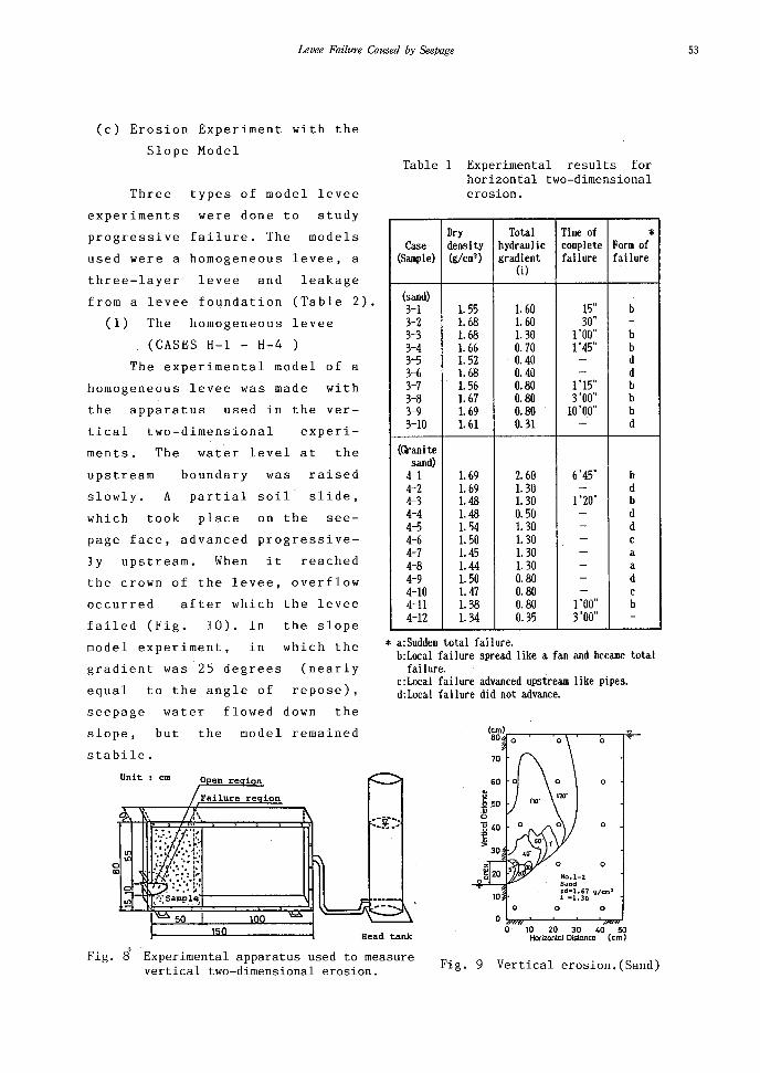
(c) Erosion Experiment with the
Slope Model
page face, advanced progressive
ly upstream. When it reached
the crown of the levee, overflow
The experimental model of a
homogeneous levee was made with
the apparatus used in the ver-
gradient was 25 degrees (nearly
equal to the angle of repose),
seepage water flowed down the
Table 1 Experimental results forhorizontal two-dimensionalerosion.
Dry Total Time of *Case densi ty hydraulic complete Form of(Sample) (gfcm3 ) gradient failure failure
(i)
(sand)3-1 1.55 1. 60 15" b3-2 1. 68 1. 60 30" -3-3 1. 68 1.30 1'00" b3-4 1. 66 0.70 1'45" bB 1. 52 0.40 - d3-6 1. 68 0.40 - d3-7 1. 56 0.80 1'15" b3-8 1. 67 0.80 3'00" b3-9 1. 69 0.80 10'00" b3-10 1.61 0.31 - d
(Granitesand)
4-1 1.69 2.60 6'45" b4-2 1. 69 1.30 - d4-3 1.48 1. 30 1'20" b4-4 1.48 0.50 - d4-5 1. 54 1. 30 - d4-6 1. 50 1. 30 - c4-7 1. 45 1. 30 - a4-8 1.44 1.30 - a4-9 1. 50 0.80 - d4-10 1.47 0.80 - c4-11 1.38 0.80 1'00" b4-12 1.34 0.35 3'00" -
* a:Sudden total failure.b:Local failure spread like a fan and became total
fai lure.c:Local failure advanced upstream like pipes.d:Local fai lure did not advance.
experi-
the slope
which thein
In10) .
after which the levee
Three types of model levee
experiments were done to study
progressive failure. The models
used were a homogeneous levee, a
three-layer levee and leakage
from a levee foundation (Table 2).
(1) The homogeneous levee
(CASES H-l - H-4
tical two-dimensional
ments. The water level at the
upstream boundary was raised
slowly. A partial soil slide,
which took place on the see-
model experiment,
occurred
failed (Fig.
Fig. 8 Experimental apparatus used to measurevertical two-dimensional erosion.
o
a
o
o
No.1-2Sandpd-l.67 CJ/cm l
i -1.30
a aaO\....,>r'---'----'--~,..",J
o 10 20 30 40 50Horizontal Distance (eml
Fig. 9 Vertical erosion.(Sand)
Head tank
100150
Failure re ion
o en re ion
50
but the model remained
Unit : em
slope,
stabile.

54 Iichiro KOHNO, Makoto NISHIGAKI and Yuji TAKESHITA
_..L.,="......_-'-_-L_..,.,J"...-_'--_"'----''''-....I 0
Fig. 10 Results of the sand slopeexperiment.
Experimental results forvertical two-dimensional erosion.
Dry Total Time of *Case density hydrauI ic complete Form of(Sample) (g/cm3 ) gradient fai lure fai lure
(0
(sand)I-I 1. 56 1.30 20" a1-2 1. 67 1. 30 1'20" a1-3 1. 74 1.30 2'00" b1-4 r. 68 0.50 14'20" b1-5 1.70 0.25 - c1-6 1. 55 0.25 - c
(Granitesoi I)
2-1 1. 35 1.30 30" a2-2 r. 40 1. 30 40" a2-3 1. 50 1.30 1'45" a2-4 1. 57 1. 30 8'45" b2-5 1. 60 1. 30 5'00" b2-6 r. 62 1.30 - e2-7 1.68 1.30 - e
* a:Sudden total failure.b:Local fai lure advanced, and piping appeared.c:Local failure did not advance.Model of the layered levee
experiment.
Sand
o 20
r-~i;--.,....--.----...--..--F:'a'::"i1U-r.--::-lIn-.-;80---Form of heed E
60 ~..~
"40 iii'5
20 ~~
Fig. 11
_..L..-"""·!;orG~ran=ile:.s;;;;O.;;.il ..........,,,.,'N'i"-""-''--=_-=.... 040 60 80 100 120 140Horizontal distane.. (em i
Table 3 Results of the seepageexperiment.
Gradient Dry tlater- InitialCase of slop density level Wide Length water Note
n (t/m3 ) (cm) (em) (cm) content(:()
H-1 35 1. 66 75 7.7 -H-2 35 1. 63 75 . 9. 7 TsukinowaH-3 25 1.68 50 9.2 -H-4 25 1. 68 50 6.6 Tsukinowa
L-1 35 1. 63 50 15 62 10.6 -L-2 35 1. 63 50 15 62 7.0 TsukinowaL-3 25 r. 63 45 10 75.5 9.2 -L-4 25 1.63 99 10 75.5 8.5 -L-5 25 1. 63 140 10 75.5 6.7 -
B-1 35 1. 63 55 20 54.3 9.2 -B-2 35 1. 63 55 20 1ll.4 6.8 -
H:Homogeneous leveeL:Three-layer leveeB:Leakage from the levee foundation
Levee Failure Caused by Seepage
(2) The three-layered levee ( CASES L-l - L-5 )
A three-layered levee model was constructed of sand and granite
soil as shown in Fig. 11. In L-l and L-5, the levee failed because
of piping in the sand layer, but in L-3 and L-4 it did not fail.
Fig. 11 shows that after the appearance of the seepage face, the sand
layer failed up to the angle of saturated repose (24-25 degrees) and
roofing took place along the boundary face between the sand and
granite soil layers. The levee failed successively because of the
outflow of the granite soil layer. Failure advanced along the upstream
side of seepage just like piping. When the critical hydraulic
gradient was reached the levee failed because boiling occurred
intermittently along the boundary face between the sand and granite
soil layers.
3.3 Theoretical Considerations
(a) Evaluation of the experiments results
In the experimental model, in which the direction of the seepage
flow was horizontal, failure occurred at the critical hydraulic
gradient reported by Terzaghi. In the model, in which the direction of
seepage flow was vertical, failure took place at nearly the critical
hydraulic gradient of Terzaghi. The critical hydraulic gradient for
horizontal seepage flow has yet to be definitively determined. At a
value greater than the critical velocity proposed by Ohno, failure
can be considered to progress rapidly because of the outflow of soil.
Clayey soil such as granite soil fails when the critical velocity of
the clay and silt fraction is low, and such fine- granite fractions
are easily washed out at a low velocity. When the pores on the
downstream side of the seepage become filled as the fine-granite
fraction flows out, the water pressure increases greatly along the
seepage face, and intermittent block failure occurs. This is why
levee failure takes place.
(b) Considerations based on the seepage theory
Taking into account the two-dimensional half circular seepage
region in Fig.12, and assuming that the seepage point is enlarged
to a half circular channel, the hydraulic gradient (i o ) is
55

56 Iichiro KOHNO. Makoto NISHIGAKI and Yuji TAKESHITA
io=(H-ho)jhln(Rjro)} ••.••• (3)
on the surfacein which r=r 0 h=h 0
of the channel, and r=R
source point.
, h=H at the
h:H
Assuming water flow in the three
dimensional half spherical seepage
region shown in Fig. 12 , the following
equation is obtained;
Fig. 12 Erosion enlargement.
. . . . .. (4)R - 1000m.B. 10mb. Oal
V
These1.0
two equations are shown in
Fig. 13. As the seepage force is
proportional to the hydraulic gra- iodient, special features can be seen
from Fig. 13. When circular or sphe- 0.5
rical soil erosion increases in the
half circular, or half spherical,
seepage region, the seepage force
decreases with the enlargement of the
region of erosion. As erosion adva-a
Two dlmens ionR - hi _ 0
o r v tn( AIr
1.0
nces around the center point of the
distance between the seepage and source
points, the seepage force is minimal.
But, as erosion advances further into
the levee, the seepage force again
increases and leads to levee failure.
piping reached point S(AB) in the
region of L width, the results shown
in Fig. 15 were obtained by
calculating the seepage discharge (0)
and the average hydraulic gradient (io )
of AB. These results show that the
phenomenon of piping has the following
special features: There is rapid
advancement in the initial phase, after
14, when linearL
B(h=O)
Fig. 14 Piping model of thetwo-dimensionalseepage region.
Fig. 13 Change in the hydraulicgradient as failureprogresses.
seepageIn the two-dimensional
region shown in Fig.

Levee Failure Caused by Seepage 57
which the speed of piping becomes
reduced. Piping speed again increases
and reaches the upstream side of the
seepage. This characteristic of piping
presents many problems for
quantitative determinations because
the distribution of the rate of seepage
discharge depends on the initial
distribution of the pressure head
before the soil is eroded, as well as
on the change in that distribution
caused by the advancement of soil
3.0
Relation of (S/L) to Q, i
1.6r-------,
1.4
O.
QO 000.0 Q2 0.4 0.6 0.8 1.0.
(SIL)explanation is
the qualitativeFig. 15
above
giveto
The
index.
understood
erosion.
4. MEASURES TO PREVENT LEVEE FAILURE CAUSED BY SEEPAGE AND LEAKAGE
4.1 Preventive Measures and Their Characteristics
Current preventive measures are listed in Table 4. These are
broadly divisible into two types; counter measures taken in advance at
dangerous places before floods occur and emergency flood-fighting
measures taken to prevent a levee from cracking or from boiling after
flooding. For the preventative measures, the basic premise is to
protect against river seepage and to drain off seepage water before
it reaches the land side. Therefore, the river side slope generally
should be covered with an impermeable material such as asphalt or
cement blocks; whereas, the land side slope should be covered with
permeable material. But, because the ground water level sometimes
reaches a dangerous level owing to infiltration of rain or overflow
water, it has been suggested that the entire surface of the levee
should be covered with soil of low permeability or with asphalt. But
if this is done, once seepage water flows into the levee the water
pressure will greatly increase and failure occur. Moreover, should
the water level in the river fall suddenly, the levee will fail
because of residual pore water pressure. Therefore, before adopting
prevention measures, it is necessary to examine the behavior of
seepage flow due to flooding.
58 Iichiro KOHNO. Makoto NISHIGAKI and Yuji TAKESHITA
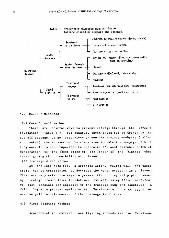
Table 4 Preventive measures against leveefailure caused by seepage and leakage.
PreventiveMeasure
CounterMeasures
Revetllent _Iof the levee L
Against leakagefrOll the levee
covering material (concrete blocks, sheets)
toe protection construction
foot protection construction
cut-off wall (sheet piles. continuous walls,che.ical grouting)
blanket
drainage (relief well. catch drain)
FloodFighting {
To preventseepage
To preventfailure
11
blanking
Tsukinowa (he.ispherical pool) constructed
Kaaadan (spherical pool) constructed
sand bagging
pi Ie driving
4.2 Counter Measures
(a) Cut-off wall method
There are several ways to prevent leakage through the levee's
foundation ( Table 4). For example, sheet piles can be driven in to
cut off seepage, or an impervious or semi-impervious membrane (called
a blanket) can be used on the river side to make the seepage path a
long one. It is most important to determine the most suitable depth of
penetration of the sheet piles or the length of the blanket when
investigating the permeability of a levee.
(b) Drainage ditch method
At the land side toe, a drainage ditch, relief well and catch
drain can be constructed to decrease the water pressure in a levee.
These are very effective ways to prevent the boiling and piping caused
by leakage from a levee foundation. But when using these measures,
we must consider the capacity of the drainage pump and construct a
filter layer to prevent soil erosion. Furthermore, constant attention
must be paid to maintenance of the drainage facilities.
4.3 Flood Fighting Methods
Representative current flood fighting methods are the Tsukinowa

Levee Failure Caused by SeePage 59
(half circular pool) and Kamadan (circular pool) methods. In terms of
basic engineering, these methods serve the same purpose, which is to
decrease the seepage face on the land side of a levee. These methods
have been used many times, but few studies have been done that
explain and verify their effectiveness; therefore, we studied the
Tsukinowa method and its application experimentally.
(a) Experimental study of the Tsukinowa method
(1) Homogeneous levee model
For the failed experimental
Tsukinowa to prevent the type of
failure shown in Fig. 16. The model
in the levee became high and the
sand under the Tsukinowa was wash
ed away. We concluded that the
efficacy of the Tsukinowa is not as
40 60 80 100 120 140Harizantal distane", (em I
20
Sand
r-"~'7""':--r---.---.---...--....--....-,ao_ Failure Une- -- Wa.tlrr table E
60 ~..~c
40 iiii'5'0
20 ~~
Fig. 16 Experimental results;the Tsukinowa method.
(Homogeneous levee model
obecause the head
we established a
however,
case in Table 3,
failed,
against the type of failure shown
in Fig. 17. As the water level
rose in the Tsukinowa, the rate of
great as expected for a homoge-
neous type of levee.
(2) Three-layer levee model
For the failed model in Fig.
seepage and the hydraulic
Eu
60-IIIuCa
40 U;'5c;
20 ~~
- Failure line- - -- Form of h~ad
27
Granite sail
r-~"='~r----r---r--..,...--.......---, 80
-.-L-""fi;rn'T""-........--"'-7.;~=""#--""' ......_---' ao 20 40 60 60 100 120
Horizontal dis tanee (em)the
gradient
a Tsukinowa
layer,
Even when there was a
permeable
we established
decreased.
highly
11,
seepage velocity became large and
local failure occurred, the soil
was not washed away because of the
Fig. 17 Experimental results;the Tsukinowa method.
( Layered levee model )
construction of a Tsukinowa is an effective
presence
Therefore,
of the Tsukinowa.
preventive
measure against failure of a layered levee.
(b) Evaluation
The Tsukinowa method usually is adopted for a steep slope and

60 Iichiro KOHNO, Makoto NISHIGAKI and Yuji TAKESHITA
pressure
permeable
Fig. 18)
heavy
the
local
point
the
Their
in
in
the
the
the Kamadan method for a gentle slope, both being set at the
of leakage caused by flooding, but a significant decrease
seepage force can not always be obtained with these measures.
effects are
(1) to decrease the hydraulic gradient by raising
head on the downstream side of seepage
(2) to prevent the concentration of seepage flow at
failure point
(3) to inhibit the outflow of soil
To prevent piping failure from spreading,
materials should be placed (e.g., gravel in
Tsukinowa.
bag
Fig. 18 A Tsukinowa constructed with gravel.
5. CONCLUSIONS
We have here reported the prediction and prevention of river
levee failures caused by seepage and leakage due to flooding. We
concluded that are
1) in determining whether there is progressive failure of a
levee, the effect of cohesion at the critical hydraulic gradient and
the process of progressive failure can be shown by one- and two
dimensional model experiments of piping and erosion. Our experimental
results agreed qualitatively with results obtained by the seepage
showed
in the
theory.
2) results of a vertical one-dimensional experiment showed that
the length of the experimental specimen must be more than l2cm,
because at less than l2cm, our experimental results were effected by
the open region and specimen failed at a seepage force below the
critical hydraulic gradient.
3) results of our horizontal two-dimensional experiment
that cohesive soil specimens composed of granite soil failed
form of 'pipes'.
Levee Failure Caused by Seepage
4) based on the type of failure seen in the vertical two
dimensional experiment, local soil failure in one part of the seepage
face was repeated and piping advances inward on the upstream side.
5) the results of the homogeneous levse model experiment showed
that at a gradient of a levee less than 25 degrees (nearly equal to
the angle of repose) a levee remains stable, and seepage water flows
down the slope.
6) our three-layer levee model made of sand and granite soil
showed that once the seepage face appears the sand layer will fail up
to the angle of saturated repose after which roofing will take place
along the boundary face between sand and granite soil layers.
7) the Tsukinowa method, the most common Japanese flood-fighting
measure dose not always prevent the outflow of soil from the levee.
The need for heavy permeable materials placed in the tsukinowa is
indicated.
REFERENCES
[1] Akai,K.,Uno,T.(1977):Conditions for failure of river levee revet
ments,Research Report of Natural Disaster Science, pp.19-54.(in
Japanese)
[2] Fukuoka,M.,Yamamoto,K (1966): Full-scale model tests of slope
failure of river embankments,Proc. of Int. Conf. on S.M.F.E.,
Vol.2,1966,pp.467-471.
[3] Uchida,I.,Suzuki,A.,Taniguchi,Y. (1966): Seepage flow in an
embankment of sand and its fai1ure,Proc. JSCE,No.126,1966, pp.27
34.(In Japanese)
[4] Yamamura,K. (1917):Studies of a river levee from a soil mechanics
approach, A Doctoral Dissertation, Kyoto Univ.,pp.9-12.
(in Japanese)
[5] Uno,T. (1967):The stability against seepage failure of an embank
ment on permeable ground, Proc. 12th Soil Mechanics Symposium
pp.37-42. (in Japanese)
[6] Miyashita,T. (1981):Decrease in the shear strength of unsaturated
soils due to seepage ,Journal of JSSMFE, Vol.29,No.6, pp.41-47.
(in Japanese)
[8] Kohno,I. (1985): Several views of seepage and groundwater of the
execution of foundation excavation, Journal of JSSMFE,Vol.33,No.8,
61

62 Iichiro KOHNO, Makoto NISHIGAKI and Yuji TAKESHITA
pp.55-63. (in Japanese)
[9] Nakashima,H.,Matsubara,M.(1985):Observation of the piping phenome
non by X-ray radiography, Proc. 20th Annual Conf. JSSMFE,
pp.1479-1482. (in Japanese)
[10] Kenny,T.S.(1985):Internal stability of granular filters, Can.
Geotech, Vol.22,pp.215-225.
[11] Matsuo,S.,Kohno,I.(1979): Dewatering Methods, Kashima Publica
tions, pp.131-132.(in Japanese)
[12] Zaslavsky,D. and G.Kassiff (1965):Formulation of the piping mech
anism in cohesive soils,Pub.No.40,Faculty of Civil Engineering,
Technion-Israel Institute of Technology,Haifa,1965, pp.305-316.
[13] Shimura,T. (1971): Critical hydraulic gradient for coarse soil,
Report of the Central Research Institute of the Electric Power
Industry, No.71001.(in Japanese)
[14] Saitoh,T.,Miki,G (1973):Seepage failure of sand caused by verti
cal ascending seepage flow ,Proc. 28th Annual Conf. JSCE, pp.9-10.
(in Japanese)
[15] Saiki,K.Hashimoto,M. (1983):Effect of fine-grained soil on the
critical hydraulic gradient,Proc. 38th Annul Conf. JSCE, pp.247
248.(in Japanese)
[16] Hayashi,S.,Yamauchi,T. (1984):Critical velocity of Sirasu and its
application to seepage failure of ground, Ann. Conf. JSEG. (in
Japanese)
[17] Ohno,M.,Yamasaki,H.,T.,P.,Oanh (1984):Experimental studies of the
characteristic of piping in sand,Proc. 17th Annual Conf. JSSMFE,
pp.2317-2320.(in Japanese)
[18] Nishida,K:,Aoyama,C. (1981):Piping phenomenon in an unsaturated
specimen of decomposed granite soil,Proc. JSSMFE,Vol.21,No.2,
pp.141-150.(in Japanese)
[19] Kubota,K. (1955):Effect of the force of seepage water on the
stability of soil, Proc. Dep. Eng. Kobe Unv.,No.3,pp.9-16.
[20] Ohno,M.,Yamasaki,H.,T.,P.,Oanh (1984):Experimental study of the
characteristics of piping in sand (Second report),Proc. 19th
Annual Conf. JSSMFE,1984,pp.1335-1336.(in Japanese)