an experimental study on the heat pump water heater system with r
TRANSCRIPT
Purdue UniversityPurdue e-PubsInternational Refrigeration and Air ConditioningConference School of Mechanical Engineering
2008
An Experimental Study on the Heat Pump WaterHeater System with Refrigerant InjectionFei LiuRefrigeration Institute of Gree Electric Appliances
Yingjiang MaRefrigeration Institute of Gree Electric Appliances
Rong ZhuangRefrigeration Institute of Gree Electric Appliances
Follow this and additional works at: http://docs.lib.purdue.edu/iracc
This document has been made available through Purdue e-Pubs, a service of the Purdue University Libraries. Please contact [email protected] foradditional information.Complete proceedings may be acquired in print and on CD-ROM directly from the Ray W. Herrick Laboratories at https://engineering.purdue.edu/Herrick/Events/orderlit.html
Liu, Fei; Ma, Yingjiang; and Zhuang, Rong, "An Experimental Study on the Heat Pump Water Heater System with RefrigerantInjection" (2008). International Refrigeration and Air Conditioning Conference. Paper 955.http://docs.lib.purdue.edu/iracc/955
2211, Page 1
An Experimental Study on the Heat Pump Water Heater System with Refrigerant Injection
Fei Liu, Hui Huang, Yingjiang Ma, Rong Zhuang
Refrigeration Institute of Gree Electric Appliances, Inc. of Zhuhai,
Zhuhai, Guangdong, China Phone: 86-756-8668863, Fax: 86-756-8668982,
E-mail: [email protected]
ABSTRACT Nowadays Heat pump water heater becomes a very hot topic in hot water industry. However it has many problems because of higher condensing temperature and large-scale operation conditions. Based on the problems, this paper presents a prototype which was assembled using a rotary compressor with refrigerant injection port. By making use of the liquid injection function of the compressor, the system can realize the quasi-dual compression in a single compressor, and thus it not only cools the compressor down, but also makes it possible for a simple heat pump system to operate in cold regions. The working principles and the basic features of the model are introduced in this paper. The operation performance was tested at different ambient temperatures, and defrosting was also discussed. According to the theoretic analyses and experiments, measures are taken to ensure the reliability and stability of the system. The results also indicated that the heat pump water heaters could be more reliable under large-scale operation conditions with high efficiency.
1. INTRODUCTION The heat pump water heater (HPWH) uses a vapor-compression refrigeration cycle, like a refrigerator or air conditioner, and the coefficient of performance (COP) largely compensates for primary electricity conversion loss. HPWHs are commonly installed in basements, attics, garages or utility rooms, where they take heat from the air at relatively low temperature and reject heat to the water tank. During the process, most units are also cooled and dehumidified, which can be valuable. Compared with conventional electric-resistance water heaters, HPWHs have a high initial cost. However, they can save significant amounts of energy and money, and often recover the system’s extra cost within several years. Therefore, it is obvious to be energy saving, environmental friendly. However, when the hot water temperature is 55℃, the condensing temperature is higher than the hot water temperature, and the condensing temperature maybe reaches 65 , which is the upper limit for the common ℃compressor of air conditioner. Because the discharging temperature is higher than the common refrigeration system, and the system runs all the year, the compressor of HPWH must be especially taken into account. In cold regions there is even high demand on hot water supply, but owing to the technical and economical issues, air source heat pump is not considered conventionally. So the common HPWH can be only used in those areas where it is over 0 . ℃To overcome the above-mentioned problems, we assembled a prototype using a rotary compressor with refrigerant injection port which can be used in cold regions. Based on the prototype, this study performs experimental tests under different working conditions and provides some guidance for optimum design and manufacture of air source HPWH.
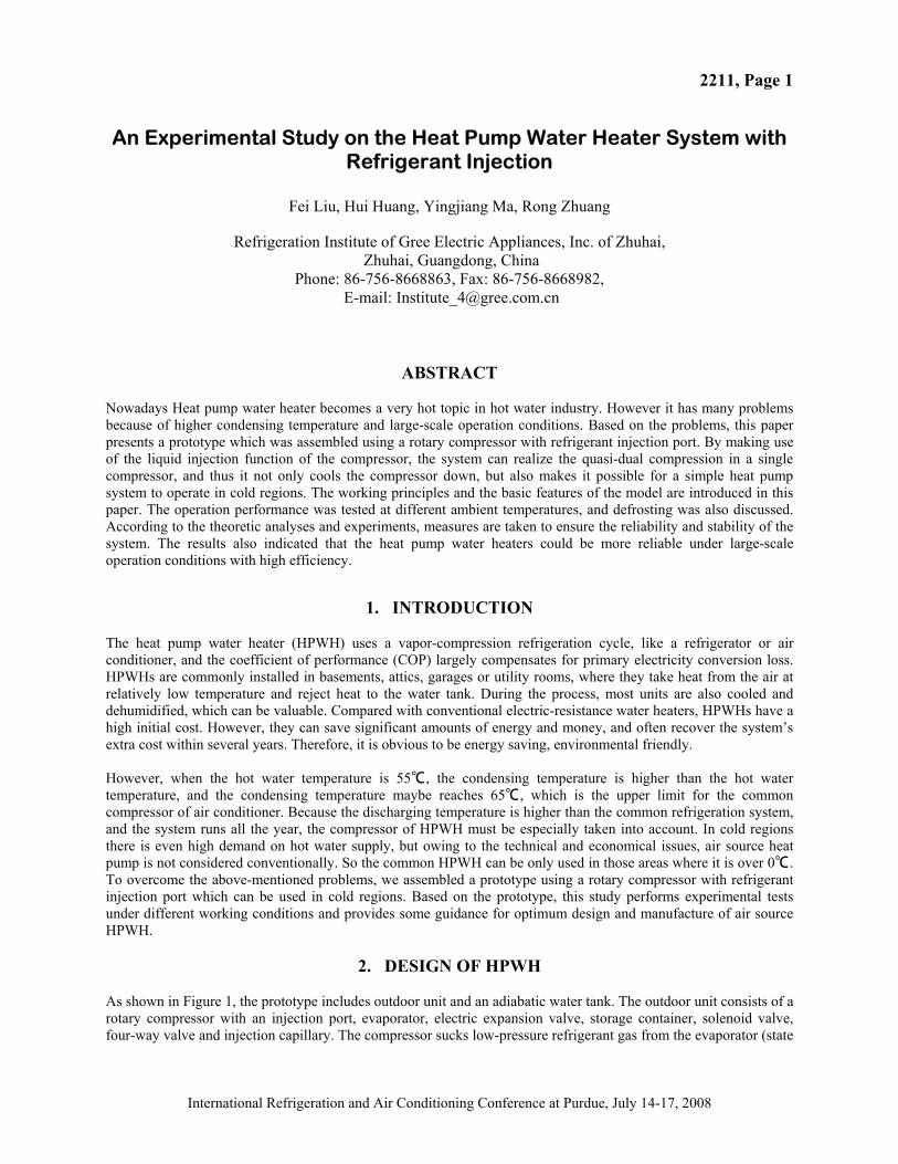
2. DESIGN OF HPWH As shown in Figure 1, the prototype includes outdoor unit and an adiabatic water tank. The outdoor unit consists of a rotary compressor with an injection port, evaporator, electric expansion valve, storage container, solenoid valve, four-way valve and injection capillary. The compressor sucks low-pressure refrigerant gas from the evaporator (state
International Refrigeration and Air Conditioning Conference at Purdue, July 14-17, 2008
2211, Page 2
1) and then discharges high-pressure gas into exchanger coil in the adiabatic water tank, where refrigerant becomes super-cooled liquid (state 4) and water is heated. The liquid refrigerant returns to the compressor in two ways: a majority of refrigerant is throttled to be low-temperature and low-pressure liquid and gas (state 5) by the electric expansion valve (called the main circuit), and little high-pressure refrigerant flows across the solenoid valve and injection capillary (state 4’) (called the liquid injection circuit). The two parts of refrigerant are mixed (state 2’) and compressed to condensing pressure. When the solenoid valve in the liquid injection circuit is cut off, the prototype operates as a conventional HPWH. When the low-temperature liquid injects compressing chamber, the compressor will cool down and work under well conditions. The cycle in P-h diagram is illustrated in Figure 2.
Td
Ts
TeTw
5
3
2'2
1
4
4'
6
Solenoid valve
Water inlet
Water outlet
Expansion valve
Injection capillary
Evaporator
Compressor
Four way valvle
Storage container
Water tank
Figure 1: The flow chart of air source heat pump water heater Figure 2: The circle of the HPWH in P-h diagram
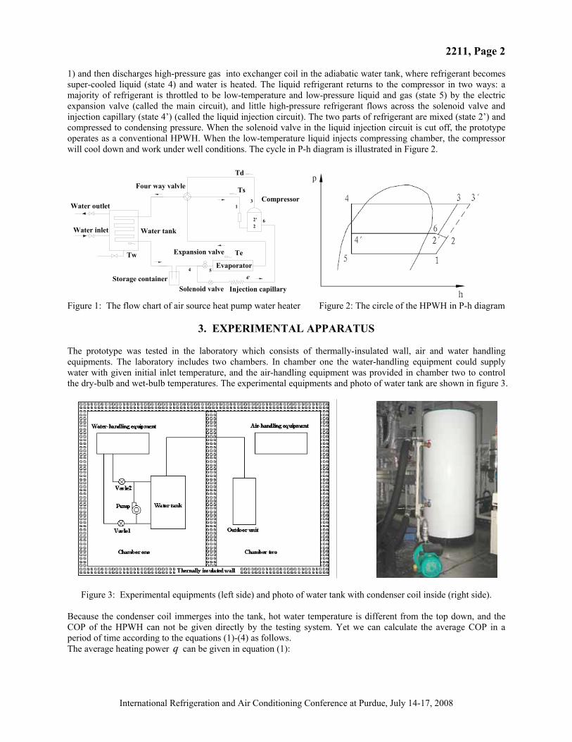
3. EXPERIMENTAL APPARATUS The prototype was tested in the laboratory which consists of thermally-insulated wall, air and water handling equipments. The laboratory includes two chambers. In chamber one the water-handling equipment could supply water with given initial inlet temperature, and the air-handling equipment was provided in chamber two to control the dry-bulb and wet-bulb temperatures. The experimental equipments and photo of water tank are shown in figure 3.
Figure 3: Experimental equipments (left side) and photo of water tank with condenser coil inside (right side). Because the condenser coil immerges into the tank, hot water temperature is different from the top down, and the COP of the HPWH can not be given directly by the testing system. Yet we can calculate the average COP in a period of time according to the equations (1)-(4) as follows. The average heating power q can be given in equation (1):
International Refrigeration and Air Conditioning Conference at Purdue, July 14-17, 2008
2211, Page 3
,2 ,1/ w w w w wq Q c V T T / (1)
Where Q is the total heating capacity in the operating period ( ); w and are density and specific heat of
water, respectively; is capacity of the water tank; Twc
wV w1, Tw2 are initial and final water temperatures in the tank. The performance of HPWH can be described as a time-average equation or a total average one. The time-average
can be shown as: COP /COP q P (2)
And the total average equation is
/COP Q W (3)
Where P and q are the time-average input power and heating capacity, respectively; W is the total electric energy consumption. The COP given as follows is the average one when the final water temperature is 55℃, which is the average temperature after water is mixed by a pump.
4. RESULTS 4.1 The Influence of Liquid Refrigerant Injection
Table 1: Experimental data under several testing conditions Items Injection capillary , mm Heating time, min Discharging temperature,℃ Solenoid valve
1 1.0×1800 61 70 2 1.0×1900 61 73 3 1.0×2000 64 74 4 1.0×2100 64 73 5 1.0×2200 62 75
open
6 1.0×2000 63 73 Open at setting temperature
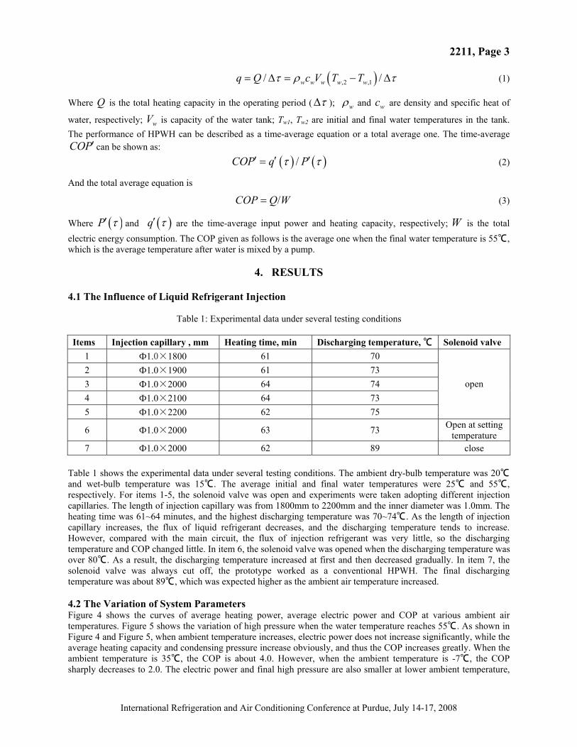
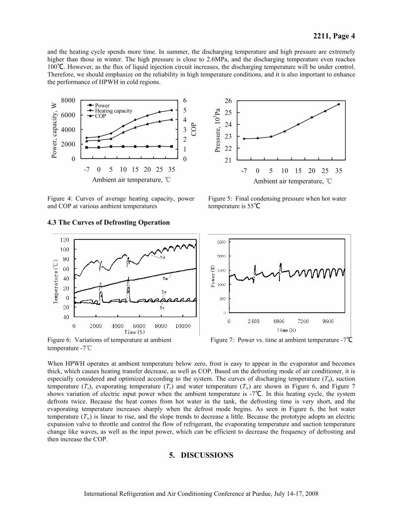
7 1.0×2000 62 89 close Table 1 shows the experimental data under several testing conditions. The ambient dry-bulb temperature was 20 ℃and wet-bulb temperature was 15 . The average initial and final water temperature℃ s were 25 and 55 , ℃ ℃respectively. For items 1-5, the solenoid valve was open and experiments were taken adopting different injection capillaries. The length of injection capillary was from 1800mm to 2200mm and the inner diameter was 1.0mm. The heating time was 61~64 minutes, and the highest discharging temperature was 70~74 . As the length of injection ℃capillary increases, the flux of liquid refrigerant decreases, and the discharging temperature tends to increase. However, compared with the main circuit, the flux of injection refrigerant was very little, so the discharging temperature and COP changed little. In item 6, the solenoid valve was opened when the discharging temperature was over 80 . ℃ As a result, the discharging temperature increased at first and then decreased gradually. In item 7, the solenoid valve was always cut off, the prototype worked as a conventional HPWH. The final discharging temperature was about 89 , which was expected ℃ higher as the ambient air temperature increased. 4.2 The Variation of System ParametersFigure 4 shows the curves of average heating power, average electric power and COP at various ambient air temperatures. Figure 5 shows the variation of high pressure when the water temperature reaches 55 . ℃ As shown in Figure 4 and Figure 5, when ambient temperature increases, electric power does not increase significantly, while the average heating capacity and condensing pressure increase obviously, and thus the COP increases greatly. When the ambient temperature is 35 , the COP is ℃ about 4.0. However, when the ambient temperature is -7 , ℃ the COP sharply decreases to 2.0. The electric power and final high pressure are also smaller at lower ambient temperature,
International Refrigeration and Air Conditioning Conference at Purdue, July 14-17, 2008
2211, Page 4
and the heating cycle spends more time. In summer, the discharging temperature and high pressure are extremely higher than those in winter. The high pressure is close to 2.6MPa, and the discharging temperature even reaches 100 .℃ However, as the flux of liquid injection circuit increases, the discharging temperature will be under control. Therefore, we should emphasize on the reliability in high temperature conditions, and it is also important to enhance the performance of HPWH in cold regions.
0
2000
4000
6000
8000
-7 0 5 10 15 20 25 35Ambient air temperature, ℃
Pow
er, c
apac
ity, W
0123456
COP
PowerHeating capacityCOP
21
22
23
24
25
26
-7 0 5 10 15 20 25 35Ambient air temperature, ℃
Pres
sure
, 105 Pa
Figure 4: Curves of average heating capacity, power and COP at various ambient temperatures
Figure 5: Final condensing pressure when hot water temperature is 55℃
4.3 The Curves of Defrosting Operation
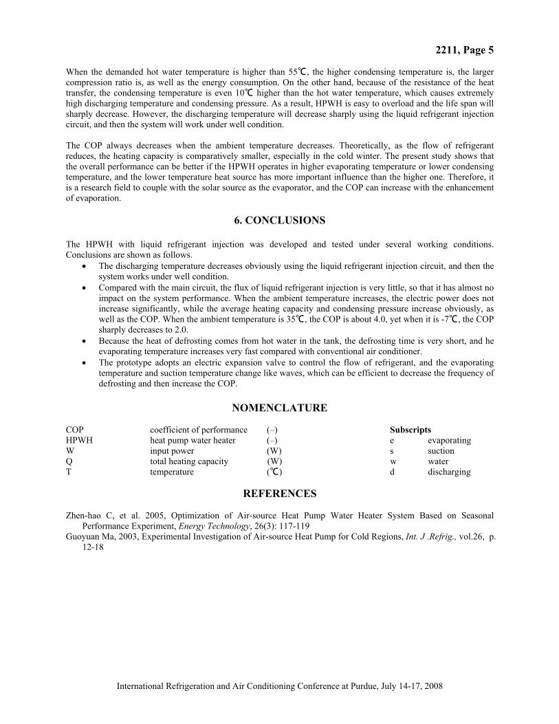
Figure 6: Variations of temperature at ambient temperature -7℃
Figure 7: Power vs. time at ambient temperature -7℃
When HPWH operates at ambient temperature below zero, frost is easy to appear in the evaporator and becomes thick, which causes heating transfer decrease, as well as COP. Based on the defrosting mode of air conditioner, it is especially considered and optimized according to the system. The curves of discharging temperature (Td), suction temperature (Ts), evaporating temperature (Te) and water temperature (Tw) are shown in Figure 6, and Figure 7 shows variation of electric input power when the ambient temperature is -7 . In th℃ is heating cycle, the system defrosts twice. Because the heat comes from hot water in the tank, the defrosting time is very short, and the evaporating temperature increases sharply when the defrost mode begins. As seen in Figure 6, the hot water temperature (Tw) is linear to rise, and the slope trends to decrease a little. Because the prototype adopts an electric expansion valve to throttle and control the flow of refrigerant, the evaporating temperature and suction temperature change like waves, as well as the input power, which can be efficient to decrease the frequency of defrosting and then increase the COP.
5. DISCUSSIONS
International Refrigeration and Air Conditioning Conference at Purdue, July 14-17, 2008
2211, Page 5
When the demanded hot water temperature is higher than 55 , the higher condensing temperature is, the ℃ larger compression ratio is, as well as the energy consumption. On the other hand, because of the resistance of the heat transfer, the condensing temperature is even 10 higher than the hot water temperature, wh℃ ich causes extremely high discharging temperature and condensing pressure. As a result, HPWH is easy to overload and the life span will sharply decrease. However, the discharging temperature will decrease sharply using the liquid refrigerant injection circuit, and then the system will work under well condition. The COP always decreases when the ambient temperature decreases. Theoretically, as the flow of refrigerant reduces, the heating capacity is comparatively smaller, especially in the cold winter. The present study shows that the overall performance can be better if the HPWH operates in higher evaporating temperature or lower condensing temperature, and the lower temperature heat source has more important influence than the higher one. Therefore, it is a research field to couple with the solar source as the evaporator, and the COP can increase with the enhancement of evaporation.
6. CONCLUSIONS
The HPWH with liquid refrigerant injection was developed and tested under several working conditions. Conclusions are shown as follows.
The discharging temperature decreases obviously using the liquid refrigerant injection circuit, and then the system works under well condition. Compared with the main circuit, the flux of liquid refrigerant injection is very little, so that it has almost no impact on the system performance. When the ambient temperature increases, the electric power does not increase significantly, while the average heating capacity and condensing pressure increase obviously, as well as the COP. When the ambient temperature is 35 , the COP is ℃ about 4.0, yet when it is -7 , ℃ the COP sharply decreases to 2.0. Because the heat of defrosting comes from hot water in the tank, the defrosting time is very short, and he evaporating temperature increases very fast compared with conventional air conditioner. The prototype adopts an electric expansion valve to control the flow of refrigerant, and the evaporating temperature and suction temperature change like waves, which can be efficient to decrease the frequency of defrosting and then increase the COP.
NOMENCLATURE COP coefficient of performance (–) Subscripts HPWH heat pump water heater (–) e evaporating W input power (W) s suction Q total heating capacity (W) w water T temperature (℃) d discharging
REFERENCES Zhen-hao C, et al. 2005, Optimization of Air-source Heat Pump Water Heater System Based on Seasonal
Performance Experiment, Energy Technology, 26(3): 117-119 Guoyuan Ma, 2003, Experimental Investigation of Air-source Heat Pump for Cold Regions, Int. J .Refrig., vol.26, p.
12-18
International Refrigeration and Air Conditioning Conference at Purdue, July 14-17, 2008
