an fmc corporation subsidiary installation, operating and...
TRANSCRIPT
Installation, Operating andMaintenance Instructions
for Crosby Style HC-HCA Safety Valves
Instruction No. IS-V3147Effective: June 1985
An FMC Corporation subsidiary
STYLE HC-HCA STEAM SAFETY VALVEIS-V-3147
TABLE OF CONTENTS
1. Description of Valve
2. Preparation of Valves for Shipment
3. Preparing the Valve for Service (Initial Installation)
4. Description of Operation
5. Set Pressure Testing and Adjustment
6. Valve Maintenance
7. Spare Parts
8. Field Service Recommendations
Attachments
Figures 1 and 2 - Illustrations of HC-HCA Valve Assembly
Figures 1A and 2A - Nomenclature of Valve Parts
Figures 3 and 4 - Valve Body As Shipped and Valve Superstructure As Shipped
Figure 5 - Illustration of Nozzle Ring Setting
Figure 6 - Illustration of Guide Ring Level With Disc Holder
Figure 7A - Effect of Nozzle Ring
Figure 7B - Effect of Guide Ring
Figures 8 and 9 - Thrust Bearing and Manual Jacking Devices
Figure 9A - Tabulation of Manual Jacking Device Accessories
Figure 10 - Hydraulic Jacking Device
Figure 10A - Tabulation for Hydraulic Jacking Device Accessories

STYLE HC-HCA STEAM SAFETY VALVE
1. Description of Valve
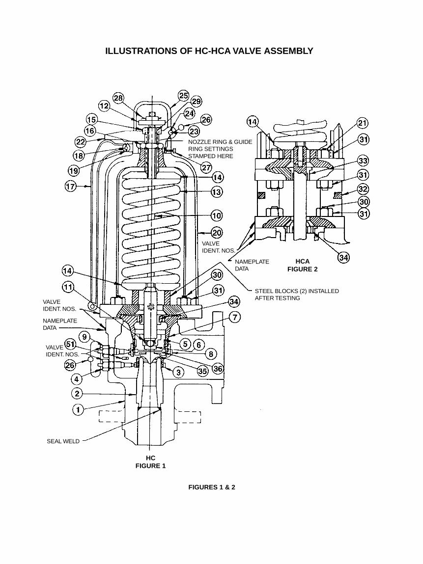
1.1Typical design of the Crosby Style HC-HCA safety valveis shown in Figures 1 and 2. The drawing shows thesafety valve assembled in cross-section, and covers theessential elements of the valve. Approved drawings sup-plied with the valves should be used when installationand/or specific information is required.
1.2Inside the body (1) is housed the upper portion of thenozzle (2), nozzle ring (3), and the adjusting ring (8).The disc insert (35) is held in place in the disc holder(5) by the disc insert pin (36). The nozzle ring and ad-justing ring are held in place by the nozzle ring set screw(4) and the adjusting ring set screw (9), which arethreaded into the body.
1.3The guide (7) is retained between the body (1) and thebonnet (20) by the bonnet studs (30) and bonnet studnuts (31).
1.4The bonnet (20) contains the spring (13), spring washer(14), and the spindle assembly (10), the lower end ofwhich is positioned on the disc bushing (6) in the discholder (5).
1.5The adjusting bolt (15) is locked in place by the adjust-ing bolt nut (16) on top of the bonnet within the cap.
1.6Manual lifting means is provided by the lever (17), leverpin (18), forked lever (22), forked lever pin (23) andspindle nut (12).
2. Preparation of Valves for Shipment
2.1All Crosby high capacity safety valves equipped withhydrostatic test plugs are shipped from the Factory intwo parts - valve body and valve superstructure. Forwelded inlet valves, this facilitates handling before andduring welding, internal gas purging during welding, ifrequired, and stress relieving procedures after welding.
2.2All safety valves equipped with hydrostatic test plugsare prepared for shipment as outlined below.
2.2.1The valve, pictured in Figure 1, is tested (as a completeassembly) for set pressure and tightness.
2.2.2The spring set compression is held by two blocks underthe lower spring washer as illustrated in Figures 1 and2.
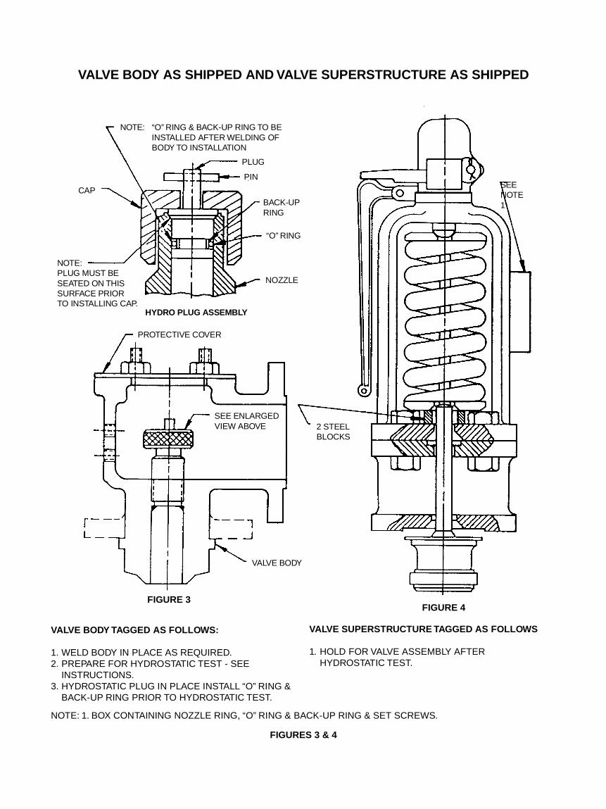
2.2.3The valve superstructure is removed from the valve bodyand the two portions are boxed and shipped separately.Each portion, ready for shipment, is illustrated in Fig-ures 3 and 4.
2.2.4Figure 3 shows the valve body as shipped to the instal-lation site. It is boxed separately from the valve super-structure and is tagged as follows if it has a weldedinlet.
INSTALL AND/OR WELD IN PLACE AS REQUIRED -PREPARE FOR HYDROSTATIC TEST. SEE INSTRUC-TION - HYDROSTATIC PLUG IN PLACE - INSTALL O-RING AND BACKUP RING PRIOR TO HYDROSTATICTEST
2.2.5Figure 4 shows the valve superstructure as shipped tothe installation site. It is boxed separately from the valvebody and is tagged as follows:
HOLD FOR ASSEMBLY AFTER HYDROSTATIC TEST
2.2.6Attached to the superstructure and in small boxes arethe following:
2.2.6.1 Nozzle Ring
2.2.6.2 Nozzle Ring Set Screw
2.2.6.3 Guide Ring Set Screw
2.2.6.4 O-Ring (for hydrostatic test)
2.2.6.5 Backup Ring (for hydrostatic test)
2.2.6.6 Seal wires
2.2.6.7 Hydrostatic Test Plug Pin
2.2.7When the parts described in Paragraphs 2.2.6.1 through2.2.6.7 are removed, be sure that the identification ofparts to valve number is maintained and that the partsare stored in a recorded allocated area to facilitate re-covery.
2.2.8If the valve body has a flanged inlet, it is tagged asfollows:
PREPARE FOR HYDROSTATIC TEST. SEE INSTRUC-TION - HYDROSTATIC PLUG IN PLACE - INSTALL O-RING AND BACKUP RING PRIOR TO HYDROSTATICTEST
3. Preparing the Valve for Service (Initial Installation)
3.1. Storage
3.1.1Safety valves are often on the job site months beforethey are installed. Unless they are properly stored andprotected, their performance may be seriously affected.Rough handling may damage flanges or cause misalign-ment of the valve parts. It is best to leave valves in theirshipment cases and store them in a dry place undercover until they are to be used.
3.2 Installation
3.2.1Inlet Piping
3.2.1.1Many valves are damaged when first placed in servicebecause of failure to clean the connections properly be-fore installation. It is essential that the valve inlet, thevessel and the line on which the valve is mounted bethoroughly cleaned of all foreign matter.
3.2.1.2Safety valves should be mounted in a vertical position,directly on the pressure vessel; the nozzle should havea well-rounded approach that provides smooth, unob-structed flow between the vessel and the valve. A safetyvalve should never be installed on a fitting having aninside diameter smaller than the inlet connection of thevalve, as restricted flow can cause faulty valve opera-tion.
3.2.2 Outlet Piping
3.2.2.1Discharge piping should be simple and direct. Wherepossible, a short vertical pipe discharging into the at-mosphere is the most desirable type of outlet pipingand affords little trouble.
3.2.2.2Discharge piping should be designed so as not to im-pose any loading on the valve. Excessive discharge pip-ing may cause seat leakage or faulty valve operation.The inside diameter of the discharge pipe must neverbe less than that of the valve outlet.
3.2.2.3Valve bodies are provided with pipe thread openingsfor drains. These should be connected to prevent anyaccumulation of fluid in the valve body. In addition, it isrecommended that discharge piping also be drained toprevent any accumulation of fluid.
3.3 Welding of Body
3.3.1The valve body should be welded to the boiler in accor-dance with applicable Code requirements. The protec-tive cover (Figure 3) should be left in place until readyfor the hydrostatic test of the unit. If visual inspection isnecessary, the cover may be removed, but should bereplaced.
3.4 Hydrostatic Testing
3.4.1Instructions for hydrostatic testing are covered in CrosbyInstruction Manual IS-V-3105.
3.5 Initial Valve Assembly
3.5.1 Cleaning and LubricationAll parts have been thoroughly cleaned prior to initialassembly and the following areas have been lubricatedat the Factory before and during assembly and shouldbe cleaned and relubricated as required. Recommendedlubricants are Never-Seez, manufactured by the Never-Seez Corp., and Molykote-G, manufactured by the DowCorning Company.
3.5.2 Lubrication Points (Reference Figure 1)
3.5.2.1 Spindle point threads (when present)
3.5.2.2 Spindle ball
3.5.2.3 Spindle rod threads for spindle nut
3.5.2.4 Spring washers at spindle and adjusting boltbearing surface.
3.5.2.5 Adjusting bolt and bonnet threads
3.5.2.6 Set screw threads
3.5.2.7 All studs and nuts
3.5.3 Initial Field Assembly Procedures
IT IS RECOMMENDED THAT ON NEW INSTALLA-TIONS UPON COMPLETION OF ALL HYDROSTATICTESTS A CROSBY SERVICE ENGINEER BEPRESENT FOR ASSEMBLY OF THE SAFETY VALVES(SEE SECTION 8).
3.5.3.1The following instructions should be followed: Checkvalve Identification Numbers and allot the proper valvesuperstructure (see Figure 3 and 4) to each valve body.Figure 1 shows the location of Valve Identification Num-ber.
3.5.3.2The valve superstructure assembly is illustrated in Fig-ure 4 and consists of the bonnet, adjusting bolt, springsubassembly, spindle, disc holder, guide ring, guide, discinsert pin and disc insert - all of which are shipped asan assembly. The nozzle ring and set screws are pack-aged together and attached to the superstructure.
CAUTIONEACH VALVE SUPERSTRUCTURE, NOZZLE RINGAND SET SCREW IS IDENTIFIED AND MATCHED TOA SPECIFIC VALVE BODY BY A TAG NUMBER ANDSHOULD BE ASSEMBLED ACCORDINGLY. AL-THOUGH ALL PARTS HAVE BEEN THOROUGHLYCLEANED, INSPECTED, LUBRICATED AND PRO-TECTED FOR SHIPMENT, THE PARTS PRIOR TOINSTALLATION SHOULD BE INSPECTED FOR EVI-DENCE OF FOREIGN MATTER OR DAMAGE. SPE-CIAL ATTENTION SHOULD BE GIVEN TO THE SEAT-ING SURFACES OF THE DISC INSERT AND NOZZLE.THESE SEATS SHOULD BE FREE FROM SURFACEDAMAGE. IF CLEANING AND/OR REPAIR IS NECES-SARY, REFER TO SECTION 6.3, REPAIR PROCE-DURE.

3.5.4 Assembly of Valve (Spring CompressionRetained) - Reference Figures 1,3 and 4
3.5.4.1 Remove the body protective cover
3.5.4.2Take nozzle ring and set screws from package. Matchthe set screws to the body and bonnet markings.
3.5.4.3Thread the nozzle ring onto the nozzle leaving the nozzlering 1/16" above the nozzle seating surface.
3.5.4.4Remove protective covering from guide (7), disc holder(3) etc. Make sure that the seat on the nozzle (2) andon the disc insert (35) are clean and undamaged.
3.5.4.5Remove the lever pin (18), lever (17), forked lever pin(23) forked lever (22) and cap (25). Do not removespindle nut (12).
CAUTIONLIFT THE VALVE SUPERSTRUCTURE SO THAT THESPINDLE IS IN THE VERTICAL POSITION, INSPECTAND CLEAN THE GUIDE-TO-BONNET FIT AND THEBODY-TO-GUIDE FIT. POSITION THE SUPERSTRUC-TURE SO THAT THE VALVE IDENTIFICATION NUM-BER STAMPED ON THE BONNET IS OPPOSITE THEOUTLET (SEE FIGURE 1).
3.5.4.6Lower the valve superstructure slowly, carefully alignthe guide with the body bowl.
CAUTIONDO NOT PERMIT ANY ROCKING MOTION OF THESPINDLE, OR ANY PART WHILE LOWERING THE SU-PERSTRUCTURE INTO THE BODY. ANY ROCKINGMOTION COULD DAMAGE SEATS.
After superstructure is in place in body inspect to besure it is fully seated in body.
IMPORTANTTHE NOZZLE RING SHOULD NOW BE LOWEREDINTO VALVE SEATING SURFACE AS FOLLOWS: LIFTUP SPINDLE (APPROXIMATELY 3/16"). WITH THESPINDLE IN THE LIFTED POSITION, PLACE ASCREWDRIVER IN THE NOZZLE RING SET SCREWHOLE AND THEN TURN THE NOZZLE RING TO THELEFT (CLOCKWISE) UNTIL THE TOP EDGE OF THENOZZLE RING IS BELOW NOZZLE SEATING SUR-FACE. THE LOCATION CAN BE CHECKED BY LOOK-ING IN THROUGH THE ADJUSTING RING SETSCREW HOLE WHILE SHINING A LIGHT THROUGHTHE NOZZLE RING SET SCREW HOLE. LOWER THESPINDLE ASSEMBLY SLOWLY UNTIL IT BOTTOMS.ROTATE THE SPINDLE CLOCKWISE SEVERALREVOLUTIONS TO MAKE SURE THAT THE SPINDLEIS FULLY SEATED ON THE DISC HOLDER ANDTHREADS OF THE SPINDLE ARE NOT ENGAGED.THE NOZZLE AND DISC INSERT SEATING SUR-FACES ARE NOW IN INTIMATE CONTACT.
3.5.4.7Install the bonnet stud nuts (31) on bonnet studs (30)and tighten uniformly.
3.5.4.8It is now necessary to remove the spacer blocks underthe lower spring washer, thereby transferring the springload to the valve seats. This is accomplished by usingthe mechanical or hydraulic jacking device. The thrustbearing shown in Figure 8 should be used for disas-sembly and assembly of valves with the maximum pres-sure ratings shown and as outlined in Paragraph 6.2.2.3.
3.5.4.8.1 Mechanical Jacking DeviceWhen using the mechanical jacking device (referenceFigure 9) install the jacking device per Paragraphs6.2.3.1.2 through 6.2.3.1.8 and raise the lower springwasher per Paragraph 6.2.3.1.8. The spacer blocks maynow be removed and the spring load transferred to thevalve seats by reversing the procedure outlined in Para-graphs 6.2.3.1.2 through 6.2.3.1.8.
3.5.4.8.2 Hydraulic Jacking DeviceWhen using the hydraulic jacking device (reference Fig-ure 10) install the jacking device per Paragraphs6.2.3.2.2 through 6.2.3.2.5 and raise the lower springwasher per Paragraph 6.2.3.2.5. The spacer blocks maynow be removed and the spring load transferred to thevalve seats by reversing the procedure outlined in Para-graphs 6.2.3.2.2 through 6.2.3.2.5.
3.5.4.9Set the nozzle ring (3) and adjusting ring (8) by follow-ing the procedure for locating rings discussed in Para-graphs 3.5.5.1 and 3.5.5.2. Lock set screws (4 and 9) inplace, making sure that the proper set screws are in-stalled and engaged in a notch and lock wire in place.
3.5.4.10Install the spindle nut (12), spindle nut cotter (28), cap(25) and lifting gear assembly before tightening the capset screw (27). Be sure that the forked lever (22) is freeto move from 1/16" to 1/8" before coming into contactwith the spindle nut. If travel is excessive, turn the spindlenut clockwise or counterclockwise to increase the levertravel. Be sure spindle nut cotter (28) is installed afterthe final adjustment.
3.5.5 Setting of Rings
3.5.5.1The nozzle ring (3) (lower ring) setting is obtained byremoving the lifting gear and reading the numbersstamped on the machined surface of the bonnet wherethe lifting gear sits. For example, NR-15 means set thenozzle ring fifteen (15) notches below contact with thedisc holder as shown in Figure 5.
3.5.5.2The adjusting ring (8) (guide upper ring) setting is ob-tained in the same manner as the nozzle ring explainedin Paragraph 3.5.5.1. For example, GR +30 means thirty(30) notches above Level position. Level is when the
bottom of the adjusting ring is even (level) with the bot-tom of the disc holder. This position is illustrated in Fig-ure 6. With the valve already on the system, level canbe obtained by inserting a metal rod with a hook on theend through the lower set screw hole and feeling theposition of the ring in relation to the disc holder.
4. Description of Operation
4.1 Correct OperationThe valve should open with a sharp pop at the pres-sure for which it is set with practically no “simmer” or“warn” and remain open, relieving full capacity at 3%overpressure. As pressure decays below the poppingpressure the valve will remain open until a pressureapproximately 4% below the set pressure is reachedand the valve will close sharply.
4.2Nozzle ring (4) is primarily for insuring good sharp open-ing action. Raising the nozzle ring (bringing closer tothe face of the disc) increases popping power and elimi-nates “simmer” or “warn.”
4.3Adjusting ring (8) is primarily for controlling blowdown.Raising the ring reduces the reactive pressures againstthe disc holder and reduces blowdown. Lowering thering increases the reactive pressures against the discholder and increases the blowdown.
4.4 OpeningThe sharp opening is produced by two stages of reac-tion working together to produce a continuous pop.
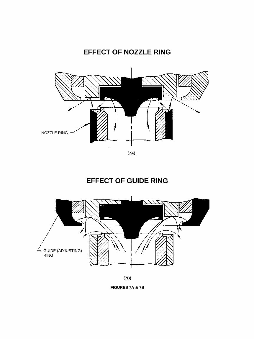
4.4.1The initial lift is produced when the steam pressureunder the disc exceeds the spring pressure. To assist instarting the popping, a small jet of steam escapes be-tween the valve seats and is deflected by a small angleon the nozzle ring (Figure 7A). This escaping steamacts on the face of the disc holder causing an unbal-ance and the valve to pop. As the disc moves vertically,steam begins to react against the (upper) adjusting ringand to push the disc up to a high lift (Figure 7B). Thereaction of the deflected steam pushes against the un-derside of the disc and lifts it still higher on an accumu-lation of pressure.
4.5 ClosingAs the boiler pressure drops, the valve disc should settleto a moderate lift and close sharply.
5. Set Pressure Testing and AdjustmentThe set pressure of a safety valve may be checked bythe following two methods with the valve on thesystem:
5.1 Set Pressure Testing on System
5.1.1 Air Set Pressure DeviceThe first method is through the use of an Air Set Pres-sure Device. This allows set pressure testing of thesafety valves on the system at pressures below normalsystem operating pressures. This method is describedin Crosby Test Procedure No. T-1652-4, a copy of whichcan be obtained upon request from Crosby Valve & GageCompany’s Service Office (see Paragraph 8).
5.1.2 System PressureThe second method of set pressure testing is by raisingthe system pressure and popping the valve. Set pres-sure testing using this method will establish the valveset and closing pressure (blowdown). Setting the valvewith the air set pressure device is recommended priorto raising the system pressure for popping pressure test-ing. This allows the set point to be established withoutraising and lowering system pressure several times toestablish the valve set pressure. Prior to set pressuretesting and raising the system pressure, the followingitems should be checked:
5.1.2.1A pressure gage with known accuracy should be lo-cated on the system being tested.
5.1.2.2Outlet piping should be anchored sufficiently to preventany vibrations while the valve is discharging; it shouldbe direct and there should be no obstructions to restrictthe safety valve discharging.
5.1.2.3Nozzle ring and adjusting ring should be set perParagraph 3.5.4.9
5.1.2.4Set screws should be locked into the body and lock wiredand the tapped holes for drains in the body should beconnected to the drain.
5.1.2.5Lifting gear should be securely fastened to the valve toassist personnel testing the valve. A rope may be at-tached through the hole provided in the lever (17) shouldmechanical lifting be necessary.
5.1.2.6Communications should be set up between control roomand the system being tested and personnel in the testarea.
CAUTIONALL SAFETY VALVES ON THE SYSTEM EXCEPT THEVALVE WHICH IS TO BE POPPED SHOULD BEGAGGED. SYSTEM PRESSURE SHOULD BE 70% OFVALVE SET PRESSURE BEFORE GAGGING. THIS ISTO PREVENT ADDED LOADS FROM BEING APPLIEDTO THE SPINDLE DUE TO THERMAL EXPANSION.GAGGING MUST BE DONE WITH CARE NOT TOOVERLOAD THE SPINDLE SINCE CONSIDERABLEDAMAGE MAY OCCUR TO THE VALVE SPINDLE ANDOTHER INTERNALS. HOWEVER, A MINIMUM FORCESHOULD BE APPLIED TO INSURE THAT THE VALVEWILL NOT OPEN.
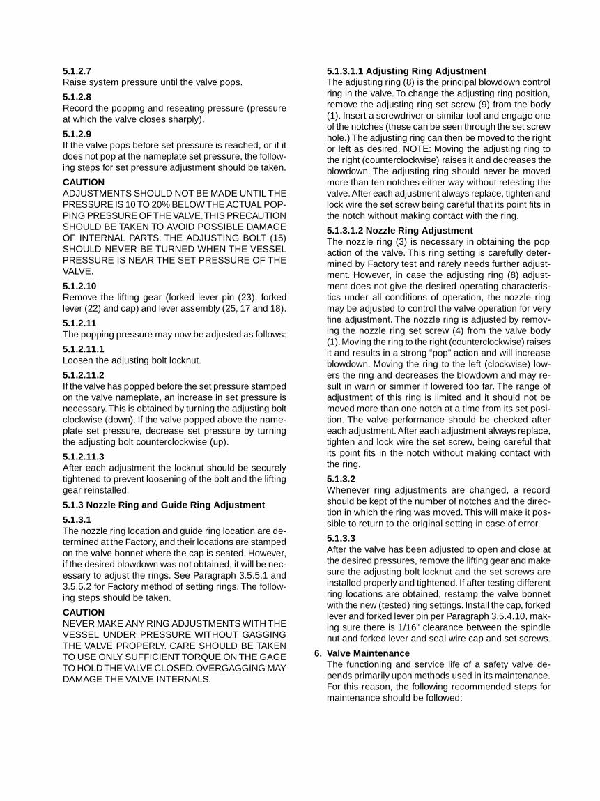
5.1.2.7Raise system pressure until the valve pops.
5.1.2.8Record the popping and reseating pressure (pressureat which the valve closes sharply).
5.1.2.9If the valve pops before set pressure is reached, or if itdoes not pop at the nameplate set pressure, the follow-ing steps for set pressure adjustment should be taken.
CAUTIONADJUSTMENTS SHOULD NOT BE MADE UNTIL THEPRESSURE IS 10 TO 20% BELOW THE ACTUAL POP-PING PRESSURE OF THE VALVE. THIS PRECAUTIONSHOULD BE TAKEN TO AVOID POSSIBLE DAMAGEOF INTERNAL PARTS. THE ADJUSTING BOLT (15)SHOULD NEVER BE TURNED WHEN THE VESSELPRESSURE IS NEAR THE SET PRESSURE OF THEVALVE.
5.1.2.10Remove the lifting gear (forked lever pin (23), forkedlever (22) and cap) and lever assembly (25, 17 and 18).
5.1.2.11The popping pressure may now be adjusted as follows:
5.1.2.11.1Loosen the adjusting bolt locknut.
5.1.2.11.2If the valve has popped before the set pressure stampedon the valve nameplate, an increase in set pressure isnecessary. This is obtained by turning the adjusting boltclockwise (down). If the valve popped above the name-plate set pressure, decrease set pressure by turningthe adjusting bolt counterclockwise (up).
5.1.2.11.3After each adjustment the locknut should be securelytightened to prevent loosening of the bolt and the liftinggear reinstalled.
5.1.3 Nozzle Ring and Guide Ring Adjustment
5.1.3.1The nozzle ring location and guide ring location are de-termined at the Factory, and their locations are stampedon the valve bonnet where the cap is seated. However,if the desired blowdown was not obtained, it will be nec-essary to adjust the rings. See Paragraph 3.5.5.1 and3.5.5.2 for Factory method of setting rings. The follow-ing steps should be taken.
CAUTIONNEVER MAKE ANY RING ADJUSTMENTS WITH THEVESSEL UNDER PRESSURE WITHOUT GAGGINGTHE VALVE PROPERLY. CARE SHOULD BE TAKENTO USE ONLY SUFFICIENT TORQUE ON THE GAGETO HOLD THE VALVE CLOSED. OVERGAGGING MAYDAMAGE THE VALVE INTERNALS.
5.1.3.1.1 Adjusting Ring AdjustmentThe adjusting ring (8) is the principal blowdown controlring in the valve. To change the adjusting ring position,remove the adjusting ring set screw (9) from the body(1). Insert a screwdriver or similar tool and engage oneof the notches (these can be seen through the set screwhole.) The adjusting ring can then be moved to the rightor left as desired. NOTE: Moving the adjusting ring tothe right (counterclockwise) raises it and decreases theblowdown. The adjusting ring should never be movedmore than ten notches either way without retesting thevalve. After each adjustment always replace, tighten andlock wire the set screw being careful that its point fits inthe notch without making contact with the ring.
5.1.3.1.2 Nozzle Ring AdjustmentThe nozzle ring (3) is necessary in obtaining the popaction of the valve. This ring setting is carefully deter-mined by Factory test and rarely needs further adjust-ment. However, in case the adjusting ring (8) adjust-ment does not give the desired operating characteris-tics under all conditions of operation, the nozzle ringmay be adjusted to control the valve operation for veryfine adjustment. The nozzle ring is adjusted by remov-ing the nozzle ring set screw (4) from the valve body(1). Moving the ring to the right (counterclockwise) raisesit and results in a strong “pop” action and will increaseblowdown. Moving the ring to the left (clockwise) low-ers the ring and decreases the blowdown and may re-sult in warn or simmer if lowered too far. The range ofadjustment of this ring is limited and it should not bemoved more than one notch at a time from its set posi-tion. The valve performance should be checked aftereach adjustment. After each adjustment always replace,tighten and lock wire the set screw, being careful thatits point fits in the notch without making contact withthe ring.
5.1.3.2Whenever ring adjustments are changed, a recordshould be kept of the number of notches and the direc-tion in which the ring was moved. This will make it pos-sible to return to the original setting in case of error.
5.1.3.3After the valve has been adjusted to open and close atthe desired pressures, remove the lifting gear and makesure the adjusting bolt locknut and the set screws areinstalled properly and tightened. If after testing differentring locations are obtained, restamp the valve bonnetwith the new (tested) ring settings. Install the cap, forkedlever and forked lever pin per Paragraph 3.5.4.10, mak-ing sure there is 1/16" clearance between the spindlenut and forked lever and seal wire cap and set screws.
6. Valve MaintenanceThe functioning and service life of a safety valve de-pends primarily upon methods used in its maintenance.For this reason, the following recommended steps formaintenance should be followed:
6.1 General Information
6.1.1When possible, remove the valve from the systembefore dismantling (flanged inlet). In any case, thereshould be no system pressure when a valve is eitherdismantled in place or removed for shop repair.
6.1.2Nozzle and guide ring set screws are custom fitted toeach valve and are not to be interchanged.
6.1.3The spring washers are fitted to each end of the spring.The spring and washers are to be kept intact as a unit.
6.1.4Before disassembly, spare parts and service equipment(i.e., lapping compound, lapping blocks, jacking gear)should be available.
6.2 Disassembly
6.2.1 Removal of the Lifting Gear
6.2.1.1Remove the forked lever pin (23), forked lever (22), cap(25), spindle nut cotter (28) and spindle nut (12) -Figure 1.
6.2.2 Recording of Ring Settings
6.2.2.1Remove the nozzle ring set screw (4) and verifylocation - see Paragraph 3.5.5.1.
6.2.2.2Remove the adjusting (guide) ring set screw (7) andverify location see Paragraph 3.5.5.2.
6.2.3 Disassembly Retaining Spring CompressionIf the valve is to be reconditioned without retesting, theoriginal set pressure can be retained by use of a jack-ing device as shown in Figures 9 or 10. This device is aservice tool that can be obtained from Crosby Valve &Gage Company (see Section 8).
6.2.3.1Disassembly Retaining Spring Compression withMechanical Jacking Device (Refer to Figure 9)
6.2.3.1.1Measure from bottom face of bottom spring washer tobonnet flange top face and record dimension. Cut two(2) pieces of bar stock 1/8" longer than recorded usedper Paragraphs 6.2.3.1.9 through 6.2.3.2.6
6.2.3.1.2Lubricate the spindle (11) thread with “Never-Seez”,“Molykote-G”, or equivalent, and install the spindle lifter(2) on the spindle (11).
6.2.3.1.3Lubricate the thrust bearing (5, 6 and 7) with suitablebearing grease and install each part into the housing.
6.2.3.1.4The bottom thrust washer (7) is guided into position onits outside diameter. Install the cage (6) on the bottomthrust washer (7). Place the top thrust washer (5) ontop of the cage.
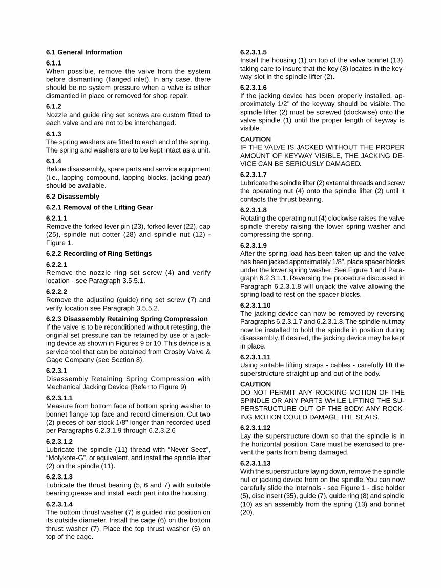
6.2.3.1.5Install the housing (1) on top of the valve bonnet (13),taking care to insure that the key (8) locates in the key-way slot in the spindle lifter (2).
6.2.3.1.6If the jacking device has been properly installed, ap-proximately 1/2" of the keyway should be visible. Thespindle lifter (2) must be screwed (clockwise) onto thevalve spindle (1) until the proper length of keyway isvisible.
CAUTIONIF THE VALVE IS JACKED WITHOUT THE PROPERAMOUNT OF KEYWAY VISIBLE, THE JACKING DE-VICE CAN BE SERIOUSLY DAMAGED.
6.2.3.1.7Lubricate the spindle lifter (2) external threads and screwthe operating nut (4) onto the spindle lifter (2) until itcontacts the thrust bearing.
6.2.3.1.8Rotating the operating nut (4) clockwise raises the valvespindle thereby raising the lower spring washer andcompressing the spring.
6.2.3.1.9After the spring load has been taken up and the valvehas been jacked approximately 1/8", place spacer blocksunder the lower spring washer. See Figure 1 and Para-graph 6.2.3.1.1. Reversing the procedure discussed inParagraph 6.2.3.1.8 will unjack the valve allowing thespring load to rest on the spacer blocks.
6.2.3.1.10The jacking device can now be removed by reversingParagraphs 6.2.3.1.7 and 6.2.3.1.8. The spindle nut maynow be installed to hold the spindle in position duringdisassembly. If desired, the jacking device may be keptin place.
6.2.3.1.11Using suitable lifting straps - cables - carefully lift thesuperstructure straight up and out of the body.
CAUTIONDO NOT PERMIT ANY ROCKING MOTION OF THESPINDLE OR ANY PARTS WHILE LIFTING THE SU-PERSTRUCTURE OUT OF THE BODY. ANY ROCK-ING MOTION COULD DAMAGE THE SEATS.
6.2.3.1.12Lay the superstructure down so that the spindle is inthe horizontal position. Care must be exercised to pre-vent the parts from being damaged.
6.2.3.1.13With the superstructure laying down, remove the spindlenut or jacking device from on the spindle. You can nowcarefully slide the internals - see Figure 1 - disc holder(5), disc insert (35), guide (7), guide ring (8) and spindle(10) as an assembly from the spring (13) and bonnet(20).
6.2.3.2Disassembly Retaining Spring Compression Using Hy-draulic Jacking Device (Refer to Figure No. 10)
6.2.3.2.1Measure from bottom face of bottom spring washer tobonnet flange top face and record dimension. Thesespacer blocks will be used per Paragraphs 6.2.3.1.9 and6.2.3.2.6.
6.2.3.2.2Install the bonnet spacer (5) on bonnet (21). Positionjacking device assembly by lifting over spindle (14) andlowering down onto bonnet spacer (5).
CAUTIONTHE PISTON (2) SHOULD BE SEATED WITHIN HOUS-ING (1) BEFORE CONTINUING. THIS SEATED POSI-TION IS REACHED WHEN THE FIRST NOTCH ONTHE PISTON (2) IS LEVEL WITH OR BELOW THE TOPOF THE HOUSING (1) AS INDICATED IN FIGURE 10.
6.2.3.2.3Lubricate the spindle threads with “Never-Seez”,“Molykote-G” or equivalent. Thread spindle adapter un-til it comes in contact with the jacking device assembly.
6.2.3.2.4Attach hand-operated hydraulic pump (7) and hose (8)
6.2.3.2.5To raise the valve spindle, pressure is applied to thejacking device assembly with the hand-operated hydrau-lic pump. This activates the piston (2) which raises thelower spring washer compressing the spring.
CAUTIONTHIS DEVICE HAS A LIMITED PISTON STROKE THATSHOULD NOT BE EXCEEDED. IF THE PISTONSTROKE IS EXCEEDED, THE SECOND NOTCH ONPISTON (2) WILL BE ABOVE THE TOP OF THE HOUS-ING (1) AND HYDRAULIC FLUID WILL FLOW FROMTHE BLEED HOLE, LOCATED IN THE HOUSING. IFHYDRAULIC FLUID IS FLOWING FROM THE BLEEDHOLE BUT PISTON STROKE HAS NOT BEEN EX-CEEDED, THE O-RING (3) AND THE BACKUP RING(4) SHOULD BE INSPECTED FOR WEAR OR DAM-AGE AND REPLACED IF NECESSARY.
6.2.3.2.6After the spring load has been taken up and the valvehas been jacked approximately 1/8", place spacer blocksunder the lower spring washer. See Figure 1 and Para-graph 6.2.3.1.1.
6.2.3.2.7The jacking device can now be removed by releasingpressure in the pump and reversing Paragraphs6.2.3.2.2 and 6.2.3.2.3.
6.2.3.2.8Thread the spindle nut on the spindle to hold the spindlein position during disassembly or leave the jacking de-vice in place. Remove adjusting ring set screw (9) (Fig-ure 1) nozzle ring set screw (4), loosen and remove thebonnet stud nuts.
6.2.3.2.9Using suitable lifting straps - cables - carefully lift thesuperstructure straight up and out of the body.
CAUTIONDO NOT PERMIT ANY ROCKING MOTION OF THESPINDLE OR ANY PARTS WHILE LIFTING THE SU-PERSTRUCTURE OUT OF THE BODY. ANY ROCK-ING MOTION COULD DAMAGE THE SEATS.
6.2.3.2.10Lay the superstructure down so that the spindle is inthe horizontal position. Care must be exercised to pre-vent the parts from being damaged.
6.2.3.2.11With the superstructure laying down, remove the spindlenut or jacking device from the spindle. You can now care-fully slide the internals, see Figure 1, disc holder (5),disc insert (35), guide (7), guide ring (8) and spindle(10) as an assembly from the spring (13) and bonnet(20).
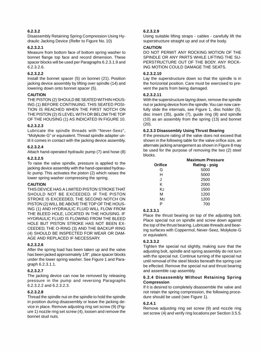
6.2.3.3 Disassembly Using Thrust BearingIf the pressure rating of the valve does not exceed thatshown in the following table for the valve orifice size, analternate jacking arrangement as shown in Figure 8 maybe used for the purpose of removing the two (2) steelblocks.
Maximum PressureOrifice Rating - psig
G 5000H 5000J 2500K 2000K2 1500M 1200M2 1200P 700
6.2.3.3.1Place the thrust bearing on top of the adjusting bolt.Place special nut on spindle and screw down againstthe top of the thrust bearing. Lubricate threads and bear-ing surfaces with Coppermol, Never-Seez, Molykote-Gor equivalent.
6.2.3.3.2Tighten the special nut slightly, making sure that theadjusting bolt, spindle and spring assembly do not turnwith the special nut. Continue turning of the special nutuntil removal of the steel blocks beneath the spring canbe effected. Remove the special nut and thrust bearingand assemble cap assembly.
6.2.4 Disassembly Without Retaining SpringCompressionIf it is desired to completely disassemble the valve andnot retain the spring compression, the following proce-dure should be used (see Figure 1).
6.2.4.1Remove adjusting ring set screw (9) and nozzle ringset screw (4) and verify ring locations per Section 3.5.5.
6.2.4.2Make a mark on the side of the adjusting bolt head andanother directly below this mark on the machined sur-face of the bonnet top. Measure the distance from thetop of the adjusting bolt to the machined bonnet sur-face between these marks and record this measure-ment. This measurement will be necessary when thevalve is reassembled.
6.2.4.3Release spring tension by loosening the adjusting boltlocknut (16) and then the adjusting bolt (15).
CAUTIONNEVER LOOSEN BONNET STUD NUTS BEFORE RE-LEASING SPRING TENSION WITH THE ADJUSTINGBOLT.
6.2.4.4Loosen and remove bonnet stud nuts (31).
6.2.4.5Using suitable lifting straps - cables - carefully lift thespring (13) and bonnet assembly straight up and overthe spindle.
CAUTIONWHEN LIFTING THIS ASSEMBLY, STRAP THESPRING TO THE BONNET TO PREVENT IT FROMFALLING OUT FROM BETWEEN THE BONNETSTRUTS.
6.2.4.6The internals, disc holder (5), disc insert (35), guide(7), guide ring (8) and spindle (10) can now be removedfrom the valve body (1) by lifting the spindle.
6.2.4.7Should overhead space negate the disassembly de-scribed in Paragraphs 6.2.4.5 and 6.2.4.6, the disas-sembly can be accomplished in the same manner asParagraphs 6.2.3.1.11 through 6.2.3.1.15.
6.3 Repair Procedure
6.3.1 Disassembly of Internal Structure
6.3.1.1Slide the guide (7) and guide ring (8) off the spindle(10) as an assembly, and unscrew the guide ring (8)from the guide (7).
6.3.1.2Remove the disc insert cotter pin (36) and the disc in-sert (35).
6.3.1.3Remove the spindle (10) from the disc holder (5) byremoving the clip ring (11) or by unscrewing the spindle(10) from the disc holder (5) depending on which seriesvalve is being worked on.
6.3.1.4Unscrew the nozzle ring (3) from the nozzle.
6.3.1.5All the parts should be cleaned thoroughly, paying spe-cial attention to guiding surfaces and the seats shouldbe lapped per Section 6.3.3.
6.3.1.6Reassemble the internal structure by reversing Para-graphs 6.3.1.1 through 6.3.1.3.
6.3.2If replacement parts are required, refer to Paragraph 7
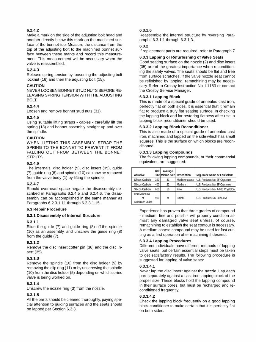
6.3.3 Lapping or Refurbishing of Valve SeatsGood seating surface on the nozzle (2) and disc insert(35) are of the greatest importance when recondition-ing the safety valves. The seats should be flat and freefrom surface scratches. If the valve nozzle seat cannotbe refinished by lapping, remachining may be neces-sary. Refer to Crosby Instruction No. I-1153 or contactthe Crosby Service Manager.
6.3.3.1 Lapping BlockThis is made of a special grade of annealed cast iron,perfectly flat on both sides. It is essential that it remainflat to produce a truly flat seating surface. In checkingthe lapping block and for restoring flatness after use, alapping block reconditioner should be used.
6.3.3.2 Lapping Block ReconditionerThis is also made of a special grade of annealed castiron, machined and lapped on the side which has smallsquares. This is the surface on which blocks are recon-ditioned.
6.3.3.3 Lapping CompoundsThe following lapping compounds, or their commercialequivalent, are suggested:
Grit AverageAbrasive Size Micron Size Description Mfg. Trade Name or Equivalent
Silicon Carbide 320 31 Medium coarse U.S. Products No. 2F Crystolon
Silicon Carbide 400 22 Medium U.S. Products No. 3F Crystolon
Silicon Carbide 600 16 Fine U.S. Products No. A-600 Crystolon
Hard Aluminiaor 900 9 Polish U.S. Products No. 38-900-A
Aluminum Oxide
Experience has proven that three grades of compound- medium, fine and polish - will properly condition al-most any damaged valve seat unless, of course,remachining to establish the seat contour is necessary.A medium coarse compound may be used for fast cut-ting as a first operation after machining if desired.
6.3.3.4 Lapping ProceduresDifferent individuals have different methods of lappingvalve seats, but certain essential steps must be takento get satisfactory results. The following procedure issuggested for lapping of valve seats:
6.3.3.4.1Never lap the disc insert against the nozzle. Lap eachpart separately against a cast iron lapping block of theproper size. These blocks hold the lapping compoundin their surface pores, but must be recharged and re-conditioned frequently.
6.3.3.4.2Check the lapping block frequently on a good lappingblock conditioner to make certain that it is perfectly flaton both sides.

6.3.3.4.3If considerable lapping is required, spread a thin coatof medium lapping compound on the block. After lap-ping with this compound, lap again with a fine compoundusing a new lapping block surface. Unless much lap-ping is called for, the first step can be omitted. Next, lapagain using a polish compound.
6.3.3.4.4Lap the block against the seat. Never rotate the blockcontinuously, but use an oscillating movement.
6.3.3.4.5When all the nicks and marks have disappeared, re-move all the compound from the block and seat. Applypolish compound to another block and lap the seat withthis. As the lapping nears completion only the compoundleft in the pores of the block should be present. Thisshould give a very smooth finish. If scratches appearthe cause is probably dirty lapping compound. Thesescratches should be removed by using compound freeof foreign material.
6.3.3.4.6Extreme care should be taken throughout to make cer-tain that the seats are kept flat.
6.3.3.5 Micro-Finishing of Valve Seats (Optional)Some valve seats such as Stellite should be lapped toa micro-finish using special compounds and the follow-ing lapping procedure. Prior to micro-finishing, the valveseats should be lapped flat and to a fine surface finishin accordance with Paragraph 6.3.3.4.5. The lappingcompound PDH-6 is used in conjunction with a lappingand cleaning thinner PDH-27 and should be used asdescribed in the following procedure:
6.3.3.5.1Clean lapping block using acetone or apply cleaningthinner PDH-27, then wipe with a clean, dry cloth orKimwipe (by Kimberly-Clark or equivalent) prior to ap-plying lapping compound.
6.3.3.5.2Apply dots of PDH-6 on the lapping block approximately1/2 to 1" apar t (not less than four per block),circumferentially on the face of the lapping block andthen apply a drop of lapping thinner PDH-27 to eachdot of compound.
6.3.3.5.3Lap the valve seat, keeping the lapping block againstthe seat and applying slight downward pressure. Dur-ing the operation, the lapping compound may begin toget stiff and movement of the lapping block more diffi-cult; remove lap from the lapped surface and add a fewdrops of lapping thinner PDH-27 to the lapping block,replace on surface being lapped and continue to rotateexerting no downward pressure.
CAUTIONTHE LAPPING COMPOUND CUTS VERY QUICKLYAND THEREFORE THE LAPPING BLOCK MUST BECHECKED PERIODICALLY TO BE SURE THAT THEBLOCK IS FLAT AND THAT A GROOVE IS NOT WORNIN THE LAPPING BLOCK DUE TO THE LAPPING OP-ERATION. WHILE LAPPING, THE LAPPING BLOCKSHOULD SLIDE SMOOTHLY OVER THE SURFACEBEING LAPPED. INDICATIONS OF ROUGHNESS INLAPPING ARE INDICATIVE OF CONTAMINATEDCOMPOUND. THE LAPPING BLOCK AND SEATINGSURFACE SHOULD BE THOROUGHLY RECLEANEDWITH THINNER (PDH-27) AND THE LAPPING OP-ERATION REPEATED.
6.3.3.5.4Continue this for approximately one minute, then removethe lapping block and clean lapped surface and the blockwith thinner PDH-27 and wipe with a clean, dry, softcloth or Kimwipe (by Kimberly-Clark or equivalent).
6.3.3.5.5If the surface is still in an unsatisfactory condition,change lapping block and repeat the above process untila satisfactory surface is obtained.
6.3.3.5.6After final lapping, clean the seating area with PDH-27and then with acetone and wipe clean with cotton.
6.4 Valve Assembly
6.4.1To reassemble the valve retaining spring compression,reverse the procedure in Sections 6.2.3.1 or 6.2.3.2.
6.4.2To reassemble the valve without retaining spring com-pression, reverse the procedure in Section 6.2.4.
7. Spare Parts
7.1Crosby recommends spare parts as shown on the out-line drawing, Figure 1.
7.1.1When ordering spare parts, the valve assembly num-ber should be given together with part number and valvesize and style. On the valve nameplate (location ofnameplate shown in Figures 1 and 2), the valve assem-bly number is shown as Shop Number. Any CrosbyBranch Office or Representative can expedite your spareparts requirements.
8. Field Service Recommendations
8.1Crosby operates an extensive field service organiza-tion capable of adjusting setting and maintaining CrosbyValves worldwide. Service Engineers are locatedthroughout the United States for fast response to ourcustomers’ needs. Service Engineers are Factory trainedand are long experienced in servicing safety valves. Itis strongly recommended that on new installations aCrosby Service Engineer be present for assembly andtesting of safety valves.

8.1.1Field Service Engineers are coordinated through theWrentham, Massachusetts office. Contact: Field Ser-vice Department, Service Manager, Crosby Valve Inc,43 Kendrick Street, Wrentham, Massachusetts 02093,(508) 384-3121, Telex 92443.
8.2 Service Equipment Available
8.2.1All service equipment mentioned in this instruction isavailable for purchase or rental and any Crosby BranchOffice, Representative or Service Manager can expe-dite your service equipment requirements.
NOMENCLATURE OF VALVE PARTSTO BE USED WITH FIGURES 1 & 2
ITEM NO. DESCRIPTION1 Body2 Nozzle
* 3 Nozzle Ring* 4 Nozzle Ring Set Screw* 5 Disc Holder
6 Disc Bushing* 7 Guide* 8 Adjusting Ring* 9 Adjusting Ring Set Screw* 10 Spindle
* 11 Clip Ring12 Spindle Nut13 Spring14 Spring Washer15 Adjusting Bolt
16 Adjusting Bolt Lock Nut17 Lever18 Lever Pin
* 19 Cotter Pin20 Bonnet
* 21 Stud22 Forked Lever23 Forked Lever Pin
* 24 Cotter Pin25 Cap
26 Seal27 Cap Screw
* 28 Spindle Nut Cotter Pin29 Adjusting Bolt Bushing30 Stud
* 31 Nut32 Cooling Spool33 Cooling Spool Bearing34 Guide Bearing
* 35 Disc Insert
* 36 Disc Insert Cotter
*Recommended Spare Parts
FIGURES 1A & 2A
ILLUSTRATIONS OF HC-HCA VALVE ASSEMBLY
NOZZLE RING & GUIDERING SETTINGSSTAMPED HERE
VALVEIDENT. NOS.
NAMEPLATEDATA
VALVEIDENT. NOS.
SEAL WELD
VALVEIDENT. NOS.
NAMEPLATEDATA
STEEL BLOCKS (2) INSTALLEDAFTER TESTING
HCFIGURE 1
HCAFIGURE 2
FIGURES 1 & 2
VALVE BODY AS SHIPPED AND VALVE SUPERSTRUCTURE AS SHIPPED
NOTE: “O” RING & BACK-UP RING TO BEINSTALLED AFTER WELDING OFBODY TO INSTALLATION
CAP
NOTE:PLUG MUST BESEATED ON THISSURFACE PRIORTO INSTALLING CAP.
PLUG
PIN
BACK-UPRING
“O” RING
NOZZLE
HYDRO PLUG ASSEMBLY
PROTECTIVE COVER
SEE ENLARGEDVIEW ABOVE
VALVE BODY
FIGURE 3
VALVE BODY TAGGED AS FOLLOWS:
1. WELD BODY IN PLACE AS REQUIRED.2. PREPARE FOR HYDROSTATIC TEST - SEE
INSTRUCTIONS.3. HYDROSTATIC PLUG IN PLACE INSTALL “O” RING &
BACK-UP RING PRIOR TO HYDROSTATIC TEST.
NOTE: 1. BOX CONTAINING NOZZLE RING, “O” RING & BACK-UP RING & SET SCREWS.
2 STEELBLOCKS
SEENOTE1
FIGURE 4
VALVE SUPERSTRUCTURE TAGGED AS FOLLOWS
1. HOLD FOR VALVE ASSEMBLY AFTERHYDROSTATIC TEST.
FIGURES 3 & 4

ILLUSTRATION OF NOZZLE RING SETTING
DISC HOLDER
NOZZLE RING
* N NOTCHESDOWN FROM TOUCHING
* N = FACTORY SETTINGSTAMPED ON BONNET
FIGURE 5
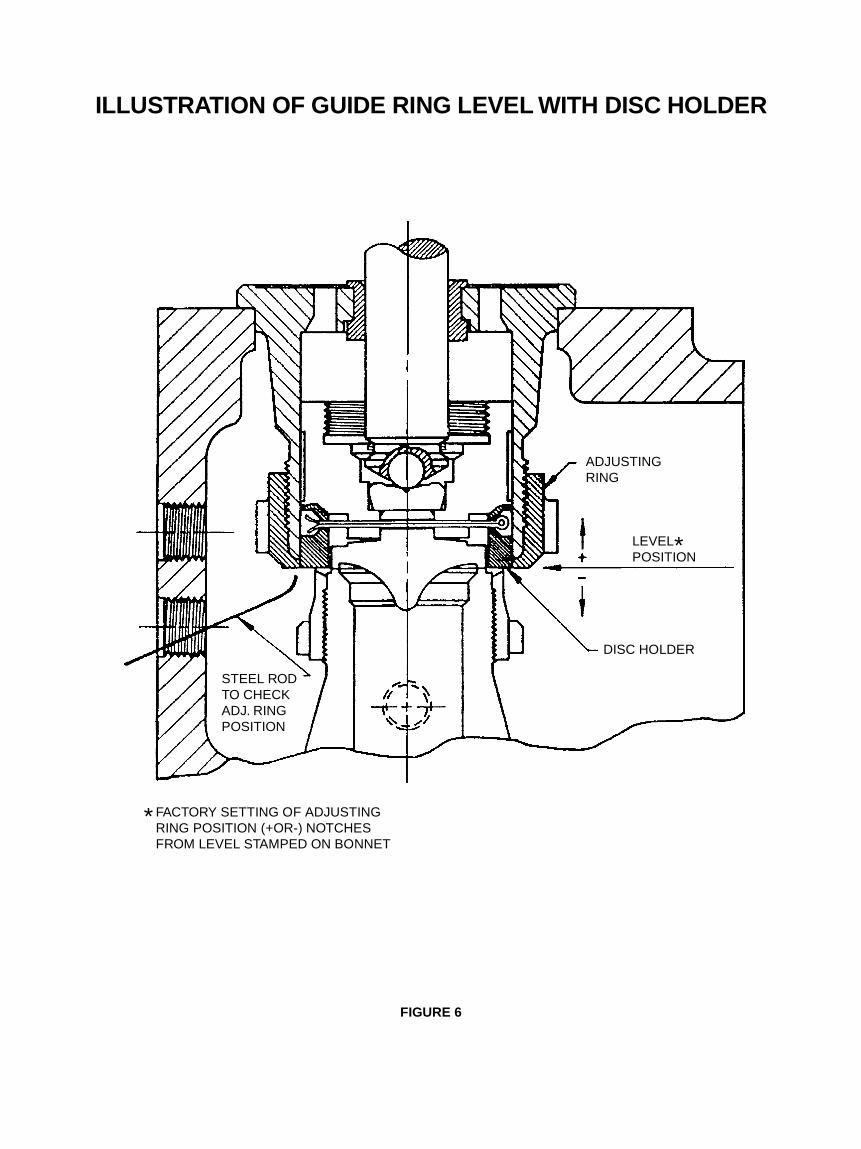
ILLUSTRATION OF GUIDE RING LEVEL WITH DISC HOLDER
ADJUSTINGRING
STEEL RODTO CHECKADJ. RINGPOSITION
LEVEL*POSITION
DISC HOLDER
* FACTORY SETTING OF ADJUSTINGRING POSITION (+OR-) NOTCHESFROM LEVEL STAMPED ON BONNET
FIGURE 6
EFFECT OF NOZZLE RING
NOZZLE RING
(7A)
EFFECT OF GUIDE RING
GUIDE (ADJUSTING)RING
(7B)
FIGURES 7A & 7B

THRUST BEARING & MANUAL JACKING DEVICES
APPROX. 1/2"OF KEYWAY
MUST BEVISIBLEBEFOREJACKING
SPECIAL NUT
*THRUST BEARING
FIGURE 9
FIGURE 8
BONNET 3 7/8 DIA.
BONNET 4 1/2 DIA.
2 5/8 DIA.BONNET
1 HOUSING
2 SPINDLE LIFTER
3 THREAD ADAPTER
4 OPERATING NUT
5 TOP THRUST WASHER
6 CAGE
7 BOTTOM THRUST WASHER
8 KEY
9 SCREW
10 VALVE SPINDLE
11 SPACER
12 ADJUSTING BOLT
20 BONNET
ANDREWS BEARING #505 OREQUIVALENT LOAD RATING 16,700 LBS.AT 10 R.P.M.
FIGURES 8 & 9
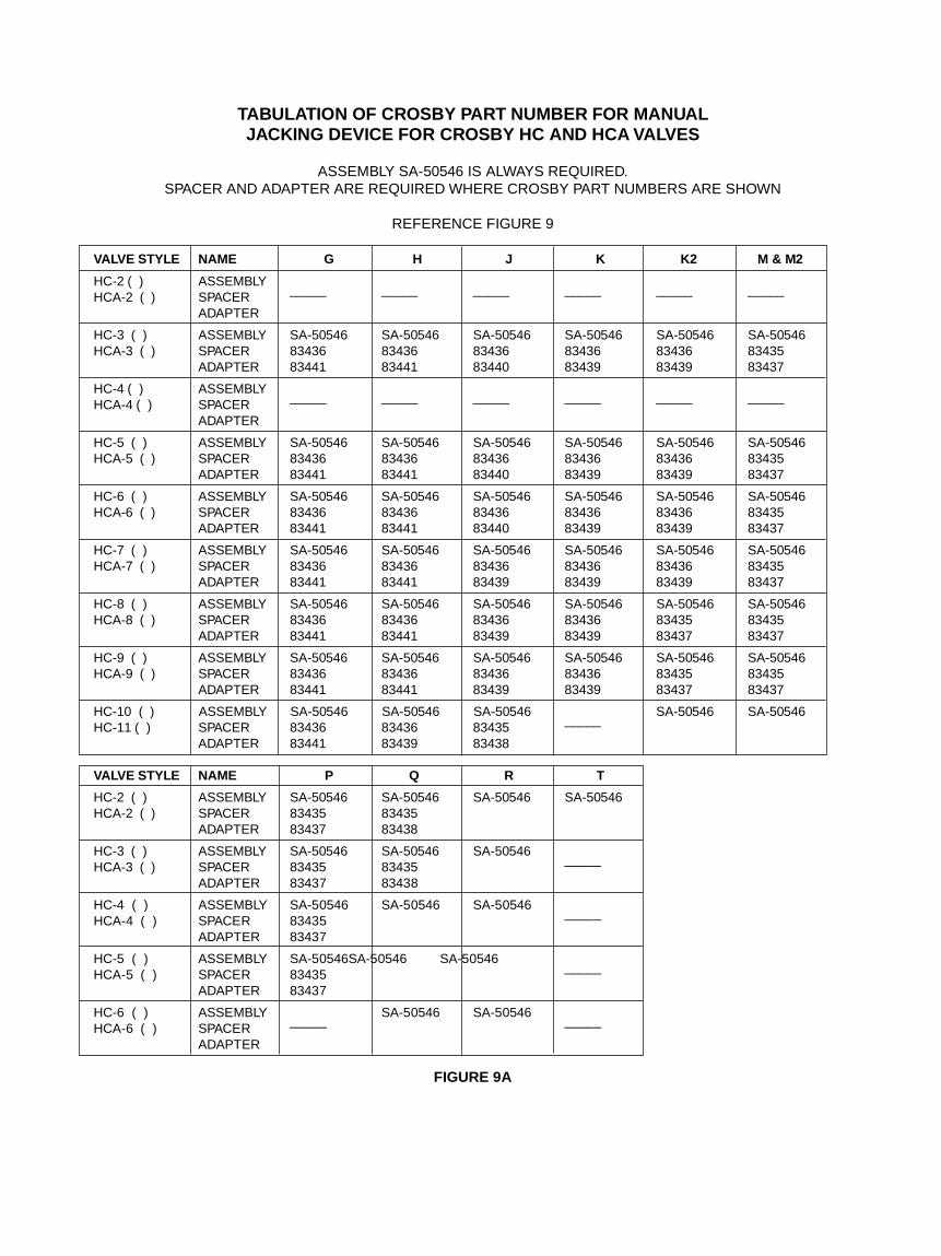
TABULATION OF CROSBY PART NUMBER FOR MANUALJACKING DEVICE FOR CROSBY HC AND HCA VALVES
ASSEMBLY SA-50546 IS ALWAYS REQUIRED.SPACER AND ADAPTER ARE REQUIRED WHERE CROSBY PART NUMBERS ARE SHOWN
REFERENCE FIGURE 9
VALVE STYLE NAME G H J K K2 M & M2
HC-2 ( ) ASSEMBLYHCA-2 ( ) SPACER _____ _____ _____ _____ _____ _____
ADAPTER
HC-3 ( ) ASSEMBLY SA-50546 SA-50546 SA-50546 SA-50546 SA-50546 SA-50546HCA-3 ( ) SPACER 83436 83436 83436 83436 83436 83435
ADAPTER 83441 83441 83440 83439 83439 83437
HC-4 ( ) ASSEMBLYHCA-4 ( ) SPACER _____ _____ _____ _____ _____ _____
ADAPTER
HC-5 ( ) ASSEMBLY SA-50546 SA-50546 SA-50546 SA-50546 SA-50546 SA-50546HCA-5 ( ) SPACER 83436 83436 83436 83436 83436 83435
ADAPTER 83441 83441 83440 83439 83439 83437
HC-6 ( ) ASSEMBLY SA-50546 SA-50546 SA-50546 SA-50546 SA-50546 SA-50546HCA-6 ( ) SPACER 83436 83436 83436 83436 83436 83435
ADAPTER 83441 83441 83440 83439 83439 83437
HC-7 ( ) ASSEMBLY SA-50546 SA-50546 SA-50546 SA-50546 SA-50546 SA-50546HCA-7 ( ) SPACER 83436 83436 83436 83436 83436 83435
ADAPTER 83441 83441 83439 83439 83439 83437
HC-8 ( ) ASSEMBLY SA-50546 SA-50546 SA-50546 SA-50546 SA-50546 SA-50546HCA-8 ( ) SPACER 83436 83436 83436 83436 83435 83435
ADAPTER 83441 83441 83439 83439 83437 83437
HC-9 ( ) ASSEMBLY SA-50546 SA-50546 SA-50546 SA-50546 SA-50546 SA-50546HCA-9 ( ) SPACER 83436 83436 83436 83436 83435 83435
ADAPTER 83441 83441 83439 83439 83437 83437
HC-10 ( ) ASSEMBLY SA-50546 SA-50546 SA-50546 SA-50546 SA-50546HC-11 ( ) SPACER 83436 83436 83435 _____
ADAPTER 83441 83439 83438
VALVE STYLE NAME P Q R T
HC-2 ( ) ASSEMBLY SA-50546 SA-50546 SA-50546 SA-50546HCA-2 ( ) SPACER 83435 83435
ADAPTER 83437 83438
HC-3 ( ) ASSEMBLY SA-50546 SA-50546 SA-50546HCA-3 ( ) SPACER 83435 83435 _____
ADAPTER 83437 83438
HC-4 ( ) ASSEMBLY SA-50546 SA-50546 SA-50546HCA-4 ( ) SPACER 83435 _____
ADAPTER 83437
HC-5 ( ) ASSEMBLY SA-50546 SA-50546 SA-50546HCA-5 ( ) SPACER 83435 _____
ADAPTER 83437
HC-6 ( ) ASSEMBLY SA-50546 SA-50546HCA-6 ( ) SPACER _____ _____
ADAPTER
FIGURE 9A
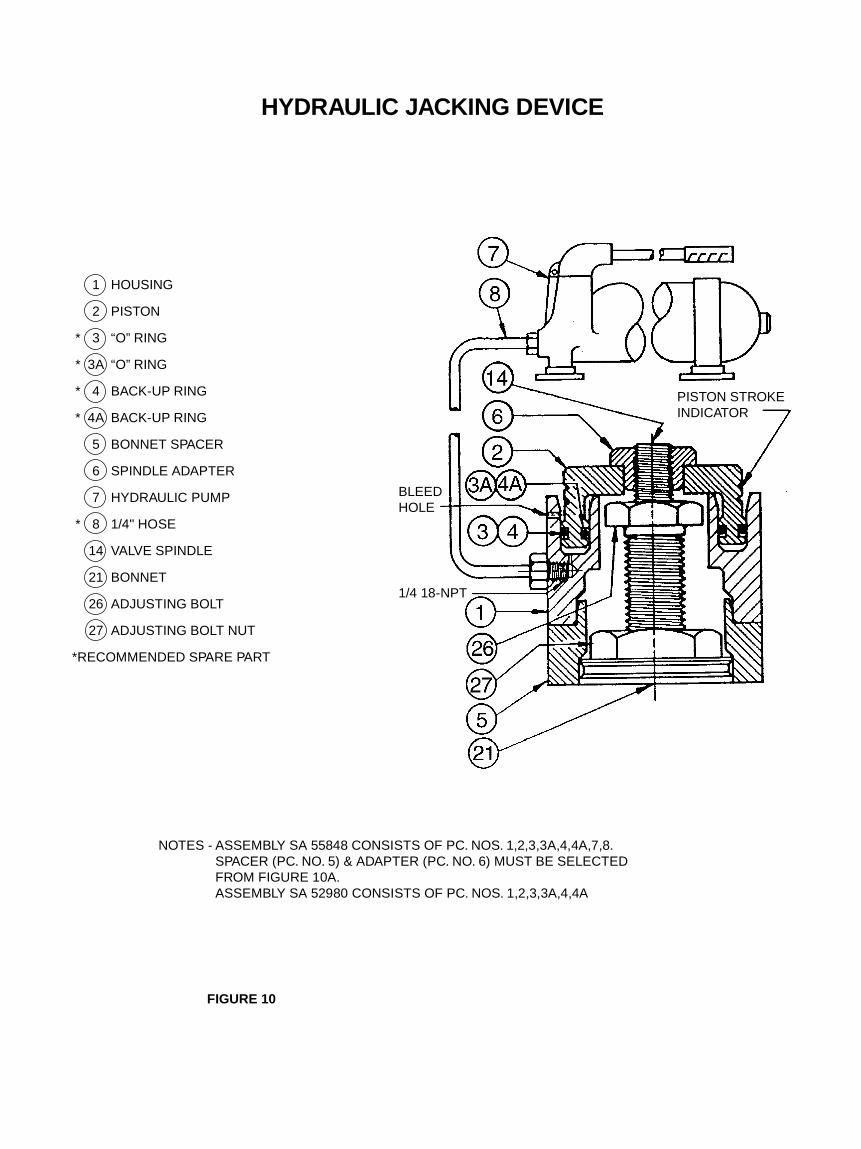
HYDRAULIC JACKING DEVICE
1 HOUSING
2 PISTON
* 3 “O” RING
* 3A “O” RING
* 4 BACK-UP RING
* 4A BACK-UP RING
5 BONNET SPACER
6 SPINDLE ADAPTER
7 HYDRAULIC PUMP
* 8 1/4" HOSE
14 VALVE SPINDLE
21 BONNET
26 ADJUSTING BOLT
27 ADJUSTING BOLT NUT
*RECOMMENDED SPARE PART
NOTES - ASSEMBLY SA 55848 CONSISTS OF PC. NOS. 1,2,3,3A,4,4A,7,8.SPACER (PC. NO. 5) & ADAPTER (PC. NO. 6) MUST BE SELECTEDFROM FIGURE 10A.ASSEMBLY SA 52980 CONSISTS OF PC. NOS. 1,2,3,3A,4,4A
FIGURE 10
BLEEDHOLE
1/4 18-NPT
PISTON STROKEINDICATOR

TABULATION OF CROSBY PART NUMBERS FOR HYDRAULICJACKING DEVICE FOR CROSBY HC AND HCA VALVES
ASSEMBLY SA-52980 IS ALWAYS REQUIREDSPACER AND ADAPTER ARE REQUIRED WHERE CROSBY PART NUMBERS ARE SHOWN
REFERENCE FIGURE 10
VALVE STYLE NAME G H J K K2 M & M2
HC-HCA 2 ( ) ______ ______ ______ ______ ______ ______ ______
HC-HCA 3 ( ) SPACER 86418 86418 86418 86418 86418 ______
ADAPTER 83551 83551 83550 82893 82893 83508
HC-HCA 4 ( ) ______ ______ ______ ______ ______ ______ ______
SPACER 86418 86418 86418 86418 86418 ______
HC-HCA 5 ( ) ADAPTER 83551 83551 83550 82893 82893 83508
SPACER 86418 86418 86418 86418 86418 ______
HC-HCA 6 ( ) ADAPTER 83551 83551 83550 82893 82893 83508
SPACER 86418 86418 86418 86418 ______ ______
HC-HCA 7 ( ) ADAPTER 83551 83551 82892 82893 83508 83508
SPACER 86418 86418 86418 86418 ______ ______
HC-HCA 8 ( ) ADAPTER 83551 83551 82893 82893 83508 83508
SPACER 86418 86418 86418 86418 ______ ______
HC-HCA 9 ( ) ADAPTER 83551 83551 82893 82893 83508 83508
SPACER 86418 86418 ______ ______ 86419 86419HC-10, 11 ( ) ADAPTER 83551 82393 83507 83509 83509
VALVE STYLE NAME P Q R T
SPACER ______ ______ 86419 86419HC-HCA 2 ( ) ADAPTER 83508 83507 83509 83509
SPACER ______ ______ 86419HC-HCA 3 ( ) ADAPTER 83508 83507 83509
______
SPACER ______ 86419 86419HC-HCA 4 ( ) ADAPTER 83508 83509 83509
______
SPACER ______ 86419 86419HC-HCA 5 ( ) ADAPTER 83508 83509 83509
______
SPACER ______ 86419 86419HC-HCA 6 ( ) ADAPTER 83508 83509 83509
______
FIGURE 10A

Crosby Products• Pressure Relief Valves for Air, Steam, Vapor and Liquid Service -
Spring Loaded and Pilot Operated• Safety Valves for Fossil and Nuclear Power Plants• QuickCrossTM crossover valves for continuous flow operations.• Pressure/Vacuum Relief Valves for Sanitary, Beverage, Food and
Pharmaceutical Industries• Valves for Chlorine, Bromine, Fluorine and other corrosive services• Valve Test Benches and Silencers• Set Pressure Verification Device (SPVD) and Valve Position Indication
(VPI) Systems• Comprehensive Test Facilities for Air, Steam and Water• Valve Service, Repair and Reconditioning, and Training
Ask for Crosby's Condensed Catalog
Replacement Spare Parts Ordering InformationFMC-Crosby recommends that a sufficient inventory of spare parts bemaintained to support process requirements. Always be sure to usegenuine FMC-Crosby parts to ensure continued product performance andwarranty.
PartsTo order parts, the following information should always be included:
1. Quantity2. Part name, i.e., (disc insert)3. Size, style, type and valve number4. Shop and/or serial number5. Original purchase order number (if the nameplate has been
destroyed).Note: The size, style, shop number, set pressure and serial number canalways be found on the valve nameplate.
Springs with WashersTo order springs with washers, the required valve set pressure must alsobe specified in addition to the other parts information. Should back pres-sure (fixed or variable) or elevated temperature exist during operation, alsospecify these conditions.
Crosby Valve Inc.
Joint Ventures - Brazil, IndiaManufacturing Affiliates - France, Japan
Sales Representatives, Assemblers, Designated Repair Centers - Worldwide Ask for Crosby Worldwide Directory
http://www.crosby.valve.gage.industry.net©1996 Crosby Valve Inc.
All rights reservedISV3147-06/85-T1-XXPrinted in U.S.A.
WARRANTYCrosby Valve Inc., Crosby Valve and Engineering Company,Limited, Crosby Services International Ltd., Crosby Valve Pte.Ltd., Crosby Valve Ltd. or Crosby Valve Sales and ServiceCorporation (collectively "Crosby") hereby warrants that thegoods delivered under contract will be free from defect in materialand workmanship for a period of 18 months from shipment or 12months from installation, whichever is earlier. Within this period,any of our products claimed defective may be returned to ourfactory after written notification to and authorization by us, and iffound to be defective after examination by us, the products will berepaired or replaced free of charge, F.O.B. our factory. Suchdefects shall be exclusive of the effects of corrosion, erosion,normal wear or improper handling or storage.
Crosby makes no representation, warranty or guarantee, ex-press or implied, with regard to our products except as specifi-cally stated. When in doubt as to the proper application of anyparticular product, you are invited to contact your nearestCROSBY office or representative. We cannot otherwise beresponsible for the selection of unsuitable equipment. Suitabilityof the material and product for the use contemplated by the buyershall be the sole responsibility of the buyer.
Except as specifically set forth above and for warranty of title,CROSBY MAKES NO WARRANTY, EXPRESS OR IMPLIED,OF ANY KIND INCLUDING WITHOUT LIMITATION, WARRAN-TIES OF MERCHANTABILITY OR FITNESS FOR A PARTICU-LAR PURPOSE.
In no event will CROSBY be liable for incidental or consequentialdamages.
WARNINGThe Product is a safety related component intended for use incritical applications. The improper application, installation ormaintenance of the Product or the use of parts or components notmanufactured by Crosby may result in a failure of the Product.The advice of a qualified engineer should be sought prior to anyuse of the Product.
Any installation, maintenance, adjustment, repair or test per-formed on the Product must be done in accordance with therequirements of all applicable Codes and Standards.
The information, specifications and technical data (the "Specifi-cations") contained in this document are subject to changewithout notice. Crosby does not warrant that the Specificationsare current and assumes no responsibility for the use or misusethereof. The Purchaser should verify that there have been nochanges to the Specifications prior to use.
An FMC Corporation subsidiary
USA Operations
Executive and SalesHeadquarters andManufacturing Plant
Crosby Valve Inc.43 Kendrick StreetP.O. Box 308Wrentham, Massachusetts02093-0308Tel: (508) 384-3121
(508) 384-7964Fax: (508) 384-8675
Asia Pacific Operations
Headquarters andSales Office
Crosby Valve Pte. Ltd.149 Gul CircleSingapore 629605Tel: (65) 862-2177Fax: (65) 862-1778
UK Operations
Headquarters, Sales Office,and Manufacturing Plant
FMC Corporation (UK) LimitedCrosby Valve and Engineering Div.Crosby RoadMarket HarboroughLeics LE16 9EE, EnglandTel: (44) (1858) 467281Tlx: (851) 34431 CROSBYGFax: (44) (1858) 434728