an improved apparatus for measuring the thermal ... · the apparatus used since 1924 in the textile...
TRANSCRIPT
U. S. DBPARTMENT OF COMMERCB NATIONAL BUREAU OF STANDARDS
RESEARCH PAPER RP1055
Part of Journal of Research of the :National Bureau of Standards, Volume 19, December 1937
AN IMPROVED APPARATUS FOR MEASURING THE THERMAL TRANSMISSION OF TEXTILES
By Richard S. Cleveland
ABSTRACT
An apparatus is described for measuring the thermal transmission of textiles. A horizontal plate is heated electrically and maintained at a constant temperature by means of a thermostat. The plate is surrounded by a guard plate which is also maintained at the same temperature to prevent lateral flow of heat into or out of the central plate. A second guard heater is placed below the central plate to prevent the downward flow of heat. The specimen to be tested is laid flat without tension on the apparatuB and enclosed in a copper hood placed several inches above it to eliminate the disturbing influence of air currents of the room. Since the thermostatic control results in an intermittent supply of heat to the central heater, an electric clock is added to the circuit, thus automatically adding the periods during which heat is being supplied. The difference in temperature from the central plate to the top of the hood is measured by means of a thermocouple and microammeter. The amount of heat supplied to the central heater per unit of time divided by the difference in temperature from the central plate to the hood and by the area of the hot plate is taken as a measure of the thermal transmission of the specimen.
The reproducibility of results, the influence of differences in temperature between the central plate and the guard plates, and the influence of the height of the hood are discussed, and values of thermal transmission for typical fabrics are given. The regulation of temperatures is essentially automatic and little attention is required from an operator except during the 15 minutes a test is actually in progress. The hot plates can be operated at any temperature desired. About seven tests can be made in an 8-hour day, allowing proper time for the attainment of a steady state. The results are usually reproducible to about 1 percent.
CONTENTS Page
1. Introduction __________________________________________ _______ ___ 676 II. Description of the apparatus___ _ _ _ _ _ _ _ _ _ _ _ _ _ _ _ _ _ _ _ _ _ _ _ _ _ _ _ _ _ _ _ _ _ _ _ 677
III. Quantities to be measured _________________________ _______ _____ __ _ 681 IV. Performance tests _____________________________________ ______ ____ 681
1. Effect of time before testing ________________________________ 681 2. Effect of a difference in temperature between the central and guard-ring plates _______________________________________ 682 3. Effect of a difference in temperature between the central plate and
the lower heater _______________________ ______ ___________ 682 4. Effect of changing the difference in temperature between the
central plate and the hood _______________ _____ ______ _____ 683 5. Effect of distance from central plate to hood_ _ _ _ _ _ _ _ _ _ _ _ _ _ _ _ _ 684 6. Reproducibility in the measurement of thermal transmission _ _ _ 684
675

676 Journal oj Research oj the National Bureau oj Standards [Vol. 19
I. INTRODUCTION
The apparatus used since 1924 in the Textile Section of the National Bureau of Standards for measuring thermal transmission of textiles is an extension by Sale 1 of a hot-plate method used by the National Bureau of Standards for measuring the thermal conductivity of insulating materials, employing the well-known guard-ring principle. With this type of apparatus, the rate of flow of heat is measured between two flat metal plates which differ in temperature by a known amount and between which the specimen is held. Because this method does not simulate sufficiently well the conditions under which textile fabrics are used as thermal insulation, it was altered by Sale by laying the fabric over the hot plate and maintaining a constant temperature difference between this plate and the air above the fabric in an air-conditioned room. Heated guard plates were used, as in the previous apparatus, to prevent loss of heat from the central plate in directions other than through the sample.
Such an arrangement better simulates the conditions of use in which the heat is supplied by the human body on one side of the fabric and transferred to the air on the other side. It is not intended to imply, either for this apparatus or the new one about to be described, that the simulation is complete. The transfer of heat from the human body through one or more layers of material to the air and surroundings without, is a very complex process and cannot be approximately duplicated by such a hot-plate apparatus except in the more simple cases. The methods described in this paper are concerned with one phase of the problem.
The chief disadvantages of Sale's apparatus are the great length of time required to adjust the electric circuits in the guard plates to attain temperature equilibrium, and the fact that no provision was made to prevent disturbances resulting from air movements in the room. The testing of a single sample with this apparatus frequently takes a whole day.
More recently Schiefer 2 developed an apparatus to make measurements similar to those of Sale. The hot plate is automatically maintained at a constant temperature by a thermostat, and heat is supplied intermittently. After the apparatus has once attained a steady state, a number of samples can be tested in a comparatively short period, because the effect of the thermal lag of the apparatus itself is eliminated by keeping it at constant temperature. The time required for a sensibly steady state to be reached in the sample itself is relatively short. When this condition is reached, the rate at which heat must be supplied to maintain a given difference in temperature from the hot plate to the air of the room is then measured over a period of half an hour. Guard heaters were not used, but the hot plate and heating element were placed in the mouth of a vacuum (Thermos) jar to prevent lateral and downward flow of heat.
While the method is both rapid and convenient, it is not altogether satisfactory for materials having high insulating value, because of a correction which must be applied for heat loss through the vacuum jar. This correction may be as much as 80 percent of the total heat input.
I P. D. Sale. Specification for constructing and operating a heat transmission apparatus for testing the heat insulating value of blankets. Tech. Pap. BS 18, 595-607 (1924) 'f269.
'Apparatus for measuring the thermal transmission of textiles. Tech. News Bu!. NBS (February 1931); J. Research NBS 13,322 (1934) RP711. A modified apparatus has been described by H . S. Schenker, Melliand Textile Mo. 5,115-117 (1933).
--~------------------------------------------------~------------~

Cterlelantl) Thermal Transmission of Textiles 677
As has already been indicated, thermal conductivity alone is not a sufficient measure of the thermal transmission of fabrics. Although the flow of heat through a thick fabric may be largely by conduction,3 the rate at which heat is transferred from its surface depends also on the convection to the air overlying the fabric and on radiation to the solid surroundings. The new instrument to be described takes account of this by enclosing the fabric with a hood that absorbs the heat transferred through the fabric and dissipates it to the outer air. The hood encloses a definite layer of air that overlies the fabric and at the same time shuts out the disturbing air currents of the room. A measure is obtained of the thermal transmission from the hot plate to the hood, which is but a few degrees warmer than the room.
The new instrument combines the automatic features and the shorttest-period characteristic of Schiefer's apparatus with the guard-ring principle used in other equipment.
II. DESCRIPTION OF THE APPARATUS
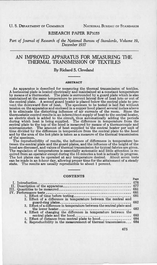
A cross sectional drawing of the apparatus is shown in figure 1. The central plate Pc, which is a hollow copper plate 6 in. square, is heated electrically by the resistance ribbon He. The cavity Oa is filled with methyl alcohol and connected by a tube, T, and sleeve, Re, to a glass U-tube containing mercury and alcohol. A rubber sleeve extracted with methyl alcohol has been found satisfactory for making the connection. As the plate becomes heated, the methyl alcohol expands into the U-tube, causing the mercury to rise in the capillary, 0, and make contact with the wire, W. This closes the coil circuit of a relay which then cuts off the heating current. Conversely, when the plate cools, the current is automatically turned on again. In this manner, the plate is regulated to a surface temperature constant within about 0.02° C. This fluctuation was made small by using a relatively large amount of a highly expansible medium, methyl alcohol, a small capillary, and numerous heat-conducting bridges across the cavity in the copper plate to facilitate the passage of heat from its under to its upper surface and thus speed transfer of heat to the expansible medium.
The central plate is surrounded by a hollow copper guard plate, P G, 2 in. wide, equipped with a similar thermostat which also holds the temperature constant within about 0.02° C.
Both hot plates were painted with a flat black lacquer to give them a high emissivity comparable to that of the human body.
The bulb, a, of the U-tube is a reservoir for both alcohol and mercury of such size that the mercury will not enter the copper plate when at its lowest temperature and the alcohol will not be driven into the capillary when it is at its highest temperature. The bulb, b, is of such size that the lowest temperature to which the plate is subjected will not cause the mercury in the bulb to be lowered sufficiently to permit air to be drawn into the plate.
These U-tubes were designed for a wide range of operating temperatures. The desired temperature is attained in two steps. The stopcock, Se, is opened, permitting the mercury to pass into reservoir R until the plate has reached the approximate temperature desired. The stopcock is then closed so that further expansion of the methyl alcohol causes the mercury to rise rapidly in the capillary and make
I I. L. Finck. Mechanlam o/heatftow Injibrou8 materIal,. BS r. Researoh 6,973-984 (1930) RP 243.
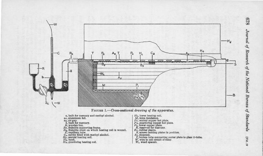
FIGURE I.-Cross-sectional drawing of the apparatus.
a. bulb for mercury and methyl alcohol. aI', aluminum Coil. ao, air gap.
b, bulb (or mercury. B, wooden box.
Bp. Bakelite supporting (rame. BB. Bakelite sheet on which heating coil is wound.
C. capillary tube. C., cavity filled with methyl alcohol.
He, central heating coil. Hd, hood. H G, guard-ring heating coil.
Eh. lower heating coil. M, mica insulation. Pc, central copper hot plate . PG, guard-ring copper hot pla~e. PL. lower copper plate.
R, reservoir for mercury . Re, rubber sleeve.
S, screws holding plates in position. Se. stopcock. T, bronze tube connecting center plate to glass U-tube.
W, wire in coil circuit o( relay. W., wood spacers .
0) 'l 00
~ .:! "'i
He! ;;l §?.
~
~ "" "" !;:o ---, "'i C>
S ."..
~ ..... ."..
"" ~ .,.,. C
~ .....
~ "" ~ ~ ~ 1;:1 ;;l
~ ~
~ -'"

Cleveland) Thermal Transmission oj Textiles 679
contact with the wire, W. Very fine adjustments of temperature can then be made by raising or lowering the wire in the capillary. By this means the temperature of the two plates can be regulated to within Xoo C of each other.4
The two hot plates are supported by the Bakelite frame, B F •
Below the frame are six layers of aluminum foil, A F , spaced about X in. apart by small wood spacers, W s, and a X6-in. copper plate, PL. Aluminum-foil insulation was used because its very low heat capacity would aid in the rapid establishment of a steady state. A lower heater, H L , just beneath the copper plate, is wound on a Xs-in. sheet of Bakelite, Bs , and electrically insulated from the copper plate by a thin sheet of mica, M. The whole unit is then mounted in a wooden box and secured by the set screws, S, at each side.
The lower heater is regulated manually to within 0.10 C of the temperature of the central hot plate.
The apparatus was designed to operate in a horizontal position to facilitate mounting the sample. The specimen to be tested is cut 13 in. square and placed over the entire surface of the hot plates and the edges of the box in a flat, ulll'ltretched condition. Its thermal properties are thus not changed by stretching or compressing.
DC 110 volf.
Sw
~ 60 'V A C 110 volts
FIGURE 2.- Heating, regulating, and timing circuits.
A copper hood is placed over the fabric to prevent air currents of the room from affecting the results. It is painted inside and out with a flat black lacquer to aid in the absorption of heat and its subsequent remdiation to the external surroundings. _ With a guard plate to prevent lateral flow of heat and the lower heater
to prevent its downward flow, heat energy supplied to the central plate must pass vertically upward through the specimen placed upon it.
Figure 2 is a wiring diagram of the heating and regulating circuits. Current from a 1l0-volt d-c. source passes through a ballast tube, BT,5 across which the drop in voltage is regulated by the resistance, R1, to 50 volts and which, therefore, delivers a virtually constant current. The circuit then divides into three paths, the first through the central heater, He; the second through the resistance, R2, which is equal to
, These plates were made as thin as practicable (~2 in .) in order to rednce the area 01 their edges. The heat conducted and radiated across the ¥Ie in . air gap between them is proportional to the area 01 their edges. To reduce this area permits more latitude in the allowablo difference in temperature between the two plates.
I This tube delivers a noarly constant current through a range in voltage of 40 to 60 volts.
680 Journal oj Research oj the National Bureau oj Standards [Vol. 19
He; and the third, through the resistance, R3. Relay 1 (Rel) is a double-pole relay which simultaneously closes the heater circuit, He, and opens the circuit, R2, thus aiding the operation of the ballast tube by keeping the equivalent resistance of the parallel circuit unchanged. R3 is set to divide the current so that the desired portion flows through the heater and the remainder by-passes through R3. Initial heating can be greatly accelerated by opening the switch, 8w, so that a much larger current passes through the heater.
The coil of a telegraphic relay (Re2) is connected across the heater so that when current flows in the heater, the relay closes the circuit of a self-starting electric clock, O. Thus the time intervals during which the current flows through the heater are automatically added by the clock.
HG is the guard-plate heater and RJ,. is a variable resistance. This circuit is opened and closed by the relay, ReS. HL is the lower heater and R5 is a variable resistance to control the current through the heater.
Tl and T2 are mercurial thermostats of the type illustrated in figure 1 in the coil circuits of the relays and the two PD's are potential dividers providing emf's for the coil circuit.
ho~d
plate FIGURE 3.-System of thermocouphs used in measuring temperature.
g, conple from centml plate to guard plate. h, couple from central plate to bood. I , couple from central plate to lower copper plate.
Cu, no. 30 copper wire. Kn, no. 28 constantan wire.
S, selecting switcb. SR, reversing switcb.
The system of copper-constantan thermocouples used to measure temperature differences is shown schematically m figure 3. Number 30 copper and no. 28 constantan (B. & S. gage) wire were used. The switch, 8, puts the desired couple in series with the micro ammeter, MA, and the reversing switch, SR, gives the current the proper direction. The temperature-emf relation was known for the particular wires used and the microampere-emf relation was found experimentally with a potentiometer and the microammeter, MA. The two relationships were then combined in a chart to give directly the temperature difference corresponding to any given microammeter reading for each couple.
The chart giving the temperature-microampere relations was computed for a cold-junction temperature of 25 0 C. The temperature of the cold junction is indicated by a thermometer placed in a shallow thermometer well in the top of the hood. For a temperature difference

Clevelandl Thermal Transmission oj Textiles 681
of 15 to 25° C, the cold junction may depart from 25° C by ± 4° C without introducing over 1 percent error in the indicated temperature difference. This is as great a range in the cold-junction temperature as would normally be experienced with this equipment. If greater precision is desired, a table of corrections may be computed and applied to the indicated temperature difference.
Four couples, g, (only two are shown in fig. 3) are in parallel, each with one junction on the inner vertical edge of the guard plate and the other on the edge of the central plate so that the combination gives the average difference in temperature between the two plates at their four edges. The couples, hand l, give the difference in temperature between the central plate and the hood, and that between the central plate and the copper plate beneath the foil insulation.
III. QUANTITIES TO BE MEASURED
The average quantity of heat supplied to the central plate per second, divided by the temperature difference between the plate and the hood and by the area of the plate, is the quantity that is determined. This quantity is that hereafter called the "thermal transmission" of the fabric and it is expressed as follows:
where I =current in amperes in the central heater,
R = resistance in ohms of the central heater=4.70 ohms, t= total time in seconds that the current, I, flows during a test,
T=total time in seconds of the duration of a test, o = difference in temperature in degrees centigrade between the
central hot plate and the top of the copper hood, A=area in square meters of the hot plate, plus one-hnJf of the
area of the air gap separating the central and guard plates=0.0232 m2, and
4.18=number of joules in 1 calorie. The ammeter, A, gives the value of I; the value of R is measured
with a bridge prior to assembling the apparatus; t is found by subtracting the initial reading of the electric clock from the final reading; T is measured with a stop watch from a moment when the current turns on to another moment about 15 minutes later when the current again turns on; and 0 is measured with the thermocouple, h. The readings of the micro ammeter for couples g and l are observed occasionally to ascertain the departure from zero during test.
IV. PERFORMANCE TESTS
1. EFFECT OF TIME BEFORE TESTING
After about 10 minutes of initial heating the relays start operating. The value of Q does not become constant at once, but in 3 hours it comes to within 0.5 to 2 percent of its final valu e. Furthermore, when one sample is removed and another of widely different insulating value is mounted in its place, Q becomes virtually constant in half
682 Journal oj Research oj the National Bureau oj Standards [Vol. 19
an hour. Therefore, before making a test, 3 hours was allowed to pass after starting the apparatus and }f hour to pass after mounting a new specimen. This permits the making of about seven tests in an 8-hour day.
2. EFFECT OF A DIFFERENCE IN TEMPERATURE BETWEEN THE CENTRAL AND GUARD-RING PLATES
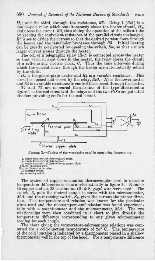
Tests were made with the central and guard plates at different temperatures in order to determine what error might arise in Q from this source. The solid lines of figure 4 show the amount of uncertainty introduced into the value of Q by operating the two plates at slightly
..J -------------------- -----« u (l) 1.0 « + l: II
a Q5~ __ -$-----
-1.0 -Q5 0 os TEMPERA TURf. 01 FFERENCE. - DEG C
FIGURE 4.-Relationship between Q and 8he temperature difference between the central and guard plates and between the central and lower copper plate.
The solid lines show the effect of maintaining the central hot plate and the guard plate at unequal temperatures.
The dotted Une shows the effect of maintaining the central hot plate and the lower copper plate at unequal temperatures.
The abscissa is the number of degrees centigrade that tbe central hot plate is above the guard ring or the lower copper plate.
different temperatures. The curves show the behavior for three fabrics of different insulating value. These curves indicate that the change in Q is not more than 0.13 cal/(secXm2XOC) for a 1 ° difference in temperature between the plates and is also virtually independent of the magnitude of Q. The difference in temperature is controlled to about 0.025° C. The error due to a lack of balance of 0.025° C is seldom greater than 0.5 percent.
3. EFFECT OF A DIFFERENCE IN TEMPERATURE BETWEEN THE CENTRAL PLATE AND THE LOWER HEATER
Tests were made with the central plate and the copper plate of the lower heater at different temperatures to determine what error might arise in the value of Q from this source. The dotted line in figure 4
-------------_ .. _-----,----------------- ,
Cleveland) Thermal Transmission oj Textiles 683
shows Q as a function of the difference in temperature between these two plates. The value of Q was found to change by 0.003 cal/(sec Xm2X °0) for a 1 ° difference in temperature over the range ± 5° 0 difference in temperature. No points fell within the range shown in figure 4. The difference in temperature is controlled to within 0.1 ° 0 and the error arising from a lack of balance of 0.10 0 is negligible.
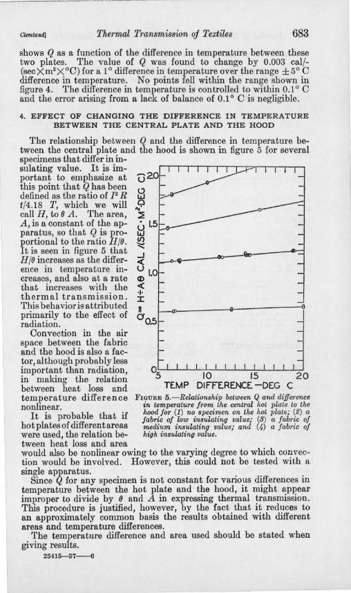
4. EFFECT OF CHANGING THE DIFFERENCE IN TEMPERATURE BETWEEN THE CENTRAL PLATE AND THE HOOD
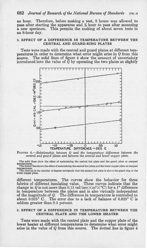
The relationship between Q and the difference in temperature between the central plate and the hood is shown in figure 5 for several specimens that differ in insulating value. It is important to emphasize at (J20 this point that Q has been defined as the ratio of 12 R t/4.18 T, which we will call H, to (J A. The area, A, is a constant of the apparatus, so that Q is proportional to the ratio H/(J. It is seen in figure 5 that H/(J increases as the difference in temperature increases, and also at a rate that increases with the thermal transmission. This behavior is attributed primarily to the effect of radiation.
Oonvection in the air space between the fabric and the hood is also a fac-tor, although probably less important than radiation, in making the relation between heat loss and temperature difference nonlinear.
It is probable that if hot plates of different areas were used, the relation between heat loss and area
...J c{ u lO <D" c{ ... I n °0.5
~~ ____ QI------------a
10 15 DIFFERENCE -DEG
FIGURE 5.-Relationship between Q and difference in temperature from the central hot plate to the hood for (1) no specimen on the hot plate; (2) a fabric of low insulating value; (3) a fabric of medium insulating value; and (4) a fabric of high insulating value.
would also be nonlinear owing to the varying degree to which convection would be involved. However, this could not be tested with a single apparatus.
Since (I, for any specimen is not constant for various differences in temperature between the hot plate and the hood, it might appear improper to divide by (J and A in expressing thermal transmission. This procedure is justified, however, by the fact that it reduces to an approximately common basis the results obtained with different areas and temperature differences.
The temperature difference and area used should be stated when giving results.
25415-37-6

684 Journal of Research of the National Bureau of Standards [Vol. 19
5. EFFECT OF DISTANCE FROM CENTRAL PLATE TO HOOD
Table 1 gives Q for several fabrics determined with hoods 4 in. and 8 in. in height. There is no consistent difference between the two sets of results and they differ only by a few percent. The 4-in. hood was used in all other tests.
TABLE 1.-Values of Q for several typical fabrics.
Fabric
Repro-1-------------;,-------1 duci-
F ab- bility ric 4-in. hood with no. 8-in. hood 4-in.
hood
9i-ln. alpaca pile___________________ 1 Do_ ___ _________ _______________ 2
%-In . alpaca pile_____________ ______ 1 Do ________ ____________________ 2
Gray blankeL_ ___________________ 1 Do ____________________________ 2
Wool underwear ___________________ ___ __ _ Do ______ __ _____ _______________ 2
30-oz kersey _____________ ____ _____ _______ _ 16-oz melton ________________________ _____ _ B . V. D . cloth ___________ ___ __ ____ __ ____ _ .Athletic shirt jersey ____________________ _ Blue serge A ___ _____ _________ ______ _____ _ Blue serge B __ ______________ __ _____ _____ _ Drill A ____________________________ ____ _ _ Drill A dyed black _____________________ _ Bare plate (flat black lacquer) __________ _
1st test 2d test
cal/(secXm'XOC) 0. 628 .628 . 753 .732
1.12 1.12 1.52 1. 54 1. 52 1. 63 1.66 1.22 1. 69 1.74 1. 71 1.68 2.17
cal/(secXm'XOC) cal/(secXm'XOC) 0.628 0.620 .616 .620 .740 _________________ _ .740 ________ ____ ___ __ _
1.12 1.14 1.09 1.12 1.52 1. 53 1. 54 ____________ _____ _ 1. 51 1. 57 1.62 __ _______________ _ 1. 69 1. 72 1. 21 1. 22 1. 68 _______ __________ _ 1. 73 1. 78 1. 71 1. 74 1.70 1. 68 2.17 ____ __ ___________ _
• Percent
0.0 1.9 1.7 1. 1 0.8 2.7 0.0
o .7 .6
1. 8 0.8 .6 .6 . 0
1.2 0. 0
.Average_____________________ __ ____ __________________ __________ ________ ____ ______________ 0.9
• .All values of Q iu this table are for 17° C difference in temperature between the central hot plate aud the hood and for au area or 0.0232 m' •
• The difference between the two determinations for the same sample is expressed as a percentago or the average value.
6. REPRODUCIBILITY IN THE MEASUREMENT OF THERMAL TRANSMISSION
The thermal transmission, Q, is given in table 1 for several typical fabrics. Duplicate tests for each specimen and tests of duplicate specimens for four of the fabrics are reported. On the average, Q was reproduced within 1 percent and in the worst example within 2.7 percent. The maximum difference in Q for two specimens of the same material is 3 percent.
The thermal transmission ranges approximately from 2.17 cal/ (sec X m2X°C) for the bare plate to 0.62 cal/(secXm2 XOO) for the %-in. alpaca pile fabric and is reproduced within ± 0.015 cal/ (secXm2 XOO) of the mean value for any sample. The apparatus is therefore sufficiently sensitive to measure relatively small differences in the thermal transmission of materials. It is particularly well adapted for routine testing and for research work involving systematic studies of thermal transmission as affected by such factors as construction, laundering, finishing treatments, and combinations of different materials.
WASHINGTON, October 1,1937.