an infinite plane loaded by a rivet of a different material
TRANSCRIPT

Pergamon 1nr.J. Soids StructuresVol. 34,No. 19,pp.2411-2496.1997
0 1997 Elsevier Science Ltd. Printed in Great Britain All rights reserved
PI1 : SOO20-7683(96)00159-X OOZO-7683/97 $17.00 + 00
AN INFINITE PLANE LOADED BY A RIVET OF A DIFFERENT MATERIAL
K. C. HO and K. T. CHAU* Department of Civil and Structural Engineering, The Hong Kong Polytechnic University,
Hung Horn, Hong Kong
(Received 15 September 1995; in revisedform 18 July 1996)
Abstract-This paper derives a closed-form solution for the stress distributions in an infinite plane loaded by a rivet of a different material under either plane stress or plane strain condition. A distinctive feature of the present analysis is that the rivet load is modelled by distributed body forces over the section of the rivet, in contrast to the commonly-used assumption of a concentrated load acting at the centre of the rivet. Two body force potentials are introduced to model the cases of conservative, uniform distributed force (Loading Case I) and non-conservative, non-uniform distributed force (Loading Case II), which is similar to those caused by shear force on a circular section. Our results show that the normal contact stress decreases with both the stiffness ratio 5 = &p, (p, and pZ are the shear moduli for the plane and rivet, respectively) and the frictional coefficient a between the plane and rivet ; conversely, the shear contact stress increases with both p and [. The normal contact stress for Loading Case I is larger than that for Loading Case II, while the opposite conclusion applies to the shear contact stress ; their differences are more apparent for larger [. Larger values of c and Jo result in higher maximum hoop stress and the corresponding location of maximum hoop stress deviates farther from the edge of contact zone ; and the maximum hoop stress resulted from Loading Case II is larger than that induced by Loading Case I. The hoop stress at the rivet hole agrees well with experimental results by Coker and Filon [Coker, E. G. and Filon, L. N. G. (1931). A Treatise on Photoelasticity, Cambridge University Press, Cambridge], Frocht [Frocht, M. M. (1949). Photoelasticity, Vol. 1, Wiley, NY], Nisida and Saito misida, M. and Saito, H. (1966). Stress distributions in a semi-infinite plate due to a pin determined by interferometric method. Exverimental Mechanics 6. 273-2791 and Hver and Liu IHver. M. W. and Liu, D. (1984). Stresses in’pin-loaded orthotropic plates using phdtoelasticity. ANTSY contractor report, CR-172498, NASA, USA]. In general, a compression zone (n > 101 > 6,) and a tension zone (0, z 101 > 0) in hoop stress are observed, where 0 is measured from the direction of the resultant rivet force and the typical value of 0, is about 160”. For the case of a rigid rivet with high friction, a second compressive zone near 0 = 0 is observed ; this differs from all previous theoretical studies, but agrees with the experimental observation by Frocht [Frocht, M. M. (1949). Photoelasticity, vol. 1, Wiley, NY]. 0 1997 Elsevier Science Ltd.
1. INTRODUCTION
The stress concentration at a circular hole in an infinite elastic plane, under either plane strain or plane stress condition, loaded by a rivet has been a classical problem in linear elasticity. The stress concentration factor at rivet-holes has application in virtually every field of design of structures and machines, such as in construction and aerospace industries (e.g., Timoshenko and Goodier, 1970; Peterson, 1974). Over the years, this problem has occupied the minds of many mathematicians and experimentalists.
In recent years, panels of marble, granite and other rocks have been commonly used as means of cladding exterior walls or curtain walls of expensive buildings in downtown areas of many big cities throughout the world. Although these rock panels are much more expensive than steel and brick cladding, the shining surfaces of rock panels provide an aesthetic and prestigious appearance of the building. Thus, there is an increasing tendency to replace brick or steel walls by the curtain walls formed by rock panels. Although the rock-panel-cladding is theoretically non-load-bearing, it must be able to withstand wind pressure. The most economical and technical feasible solution for the wind-bearing system is probably the use of a grid formed by transoms and mullions which can withstand the wind pressure. The introduction of transoms and mullions will, however, destroy a con- tinuous surface of shining rock ; thus, in practice, steel bolt- or rivet-fixing from the inside
* Author to whom correspondence should be addressed.
2477

2478 K. C. Ho and K. T. Chau
Y
Y ,_._---) t---_.
,_‘_ 1 -.._ r ,/’
--__
\\
,’ #,’
:’ 8’
Separate II zone ‘/ : \\ j\
‘\
contact __
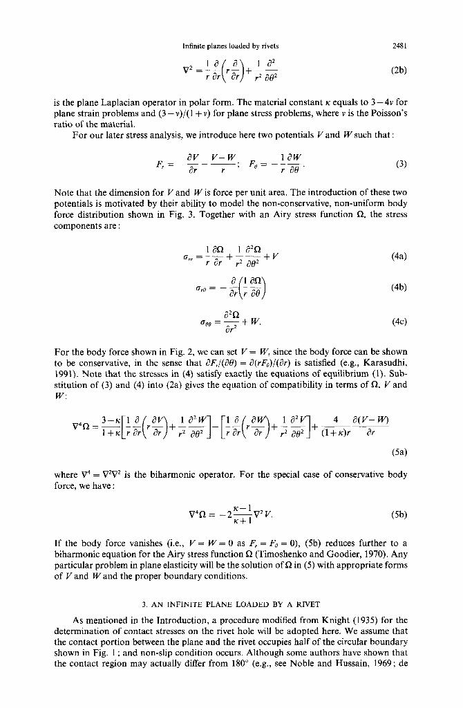
Fig. 1. A sketch for an infinite plane loaded by a rivet with resultant force P. Separation of the rivet and the infinite plane is assumed to develop within the range : ~42 < 0 < R and -n i H i -n/2,
while the non-slip contact region is within -z/2 < 0 < 7r/2.
of the building have to be used in connecting the rock panels. Most brittle failures in these rock panels actually result from the stress concentration at the rivet-rock interface under wind pressure. The breakage failure of the rock panels will cause casualties when the fragments of the panels fall onto the street level from above. Since high quality rock panels are very expensive, the use of an optimum thickness for the panels is essential to achieve an economical but safe design. To date, the method of analysis used for such design is rather primitive, and much remains to be done.
The present study does not attempt to solve the problem completely, but instead considers analytically the most fundamental problem of stress concentration in an infinite plane loaded by a rivet of a different material. The results of the present study should shed light on the more practical problem of rivet-rock panel connection. For mathematical simplicity, both the rock panel and the steel rivet are considered as isotropic elastic.
The first mathematical solution for the stress concentration around a pinned-rivet in an infinite plate was obtained by Bickley (1928) who, motivated by experimental results of photoelastic method, assumed that the rivet-induced compressive normal stress is pro- portional to cos 0 while the rivet-induced shear stress is proportional to sin3 0 cos H, where 0 is the angle measured from the x-axis along which the resultant force acts as shown in Fig. 1. Knight (1935) proposed a more realistic stress distribution on the rivet hole, which allows half of the boundary between the rivet and the infinite plate to separate (i.e., both normal and shear tractions vanish on this portion of the circular boundary). Other theoretical analyses for rivet problems include the works by Theocaris (1956) on an infinite strip, by Mori (1972) on a semi-infinite plate, and by Levy and Smith (1949) on an infinite plate with reinforced rivet hole. Experimental studies include the works by Coker and Filon (1931), Frocht and Hill (1940), Frocht (1949), Jessop et al. (1958), Cox and Brown (1964), Nisida and Saito (1966), and Hyer and Liu (1984). Taking displacement compatibility into consideration, Noble and Hussain (1969) obtained the normal contact stress between a rivet and an infinite plane in smooth contact for the case that the elastic constants of the rivet and the outer body satisfy : (I- 2v,)pL2 = p,( 1 - 2v,) (where p, and v, denote the shear modulus and Poisson’s ratio and i = 1,2 for the outer body and rivet, respectively), and de Jong (1977) and Mizushima and Hamada (1983) obtained the normal contact stress for the case of a rigid rivet. Rao (1978), Hyer and Klang (1985) and Hyer et al. (1987) have solved numerically the problem of a pin-loaded isotropic or orthotropic plate with interference fit and clearance fit. Using the collocation method, Hyer and Klang (1985) and Hyer et al. (1987) have calculated the stresses near the hole in an orthotropic plate loaded

Infinite planes loaded by rivets 2419
by a rivet of different materials, including steel, aluminium and rigid rivets. However, no closed-form solution has been proposed for the rivet of arbitrary stiffness.
Therefore, with possible application to rivet-rock panel connection, we consider here the problem of an infinite plane loaded by a rivet of arbitrary stiffness. The method of solution employed in this study is modified from those proposed by Knight (1935). Although Knight’s (1935) approach, as mentioned by Mizushima and Hamada (1983), ignores the displacement compatibility between the hole and rivet, such approach has been applied successfully by Theocaris (1956). In addition, Fig. 9 of Mizushima and Hamada (1983) showed that both the hoop and normal contact stresses predicted by Knight (1935) are comparable to both the experimental observation by Nisida and Saito (1966) and the theoretical solution by Mizushima and Hamada (1983), in which radial displacement compatibility had been accounted properly. Thus, for mathematical simplicity Knight’s (1935) approach is adopted here.
There is, however, one main problem with the shear contact stress proposed by Knight (1935). In particular, Knight (1935) assumed that the shear contact stress is proportional to sin Q on the right-hand half of the hole but equals zero on the left-hand half of the hole (see Fig. 1). This assumption predicts a jump in the shear contact stress which increases from zero at f3 = n/2 +6 to a finite value at 6’ = 71/2-d, for any arbitrarily small positive real number 6. This discontinuity in shear stress on the boundary, however, contradicts the photoelastic observation on an isotropic plate containing a pin-load by Hyer and Liu (1984). Instead, Fig. 12 of Hyer and Liu (1984) showed that the shear contact stress is roughly proportional to sin 29. Motivated by this observation, we assume here a 8-depen- dency of sin 20 for the shear contact stress.
More specifically, the rivet problem is first subdivided into two auxiliary problems. The first problem is the solution for the stress distribution in the plane loaded by a rivet of a different material, which is bonded perfectly to the plane. Then, the second auxiliary problem seeks a solution that cancels both normal and shear tractions caused by the first auxiliary problem on the left-hand half of the circular boundary but produces resultant shear and normal stresses proportional to sin 28 and cos 8 on the right-hand half, respec- tively. Note that gap is allowed to be developed on the left-hand half of the hole, as shown in Fig. 1. The stress distribution around the rivet hole will simply be the superposition of auxiliary problems one and two.
Another distinctive feature of the present study which differs from previous works is that the net force carried by the rivet is not modelled by a concentrated force acting at the centre of the rivet. The shear source transferred by the rivet is modelled here by two types of body forces distributed over the section of the rivet. The first one is the idealized distribution of uniform shear stress parallel to the direction of the net force (shown in Fig. 2) ; this approach was first proposed by Hyer and Klang (1985). The second one is a more realistic distribution that the shear stress always flows parallel to the rivet boundary but with a net resultant force (shown in Fig. 3). Discussion on this non-uniform shear stress can be found in standard text books on strength of materials and elasticity (e.g., Timoshenko and Goodier, 1970; Ryder, 1988; Gere and Timoshenko, 1990). More detailed math- ematical descriptions of both loading cases will be given in a later section.
It seems more realistic that the rivet should be considered in an infinite strip of finite width, instead of an infinite plane. Theoretically, we can follow an alternating approxi- mation method by Howland (1928, 1930) and Howland and Stevenson (1933) to obtain the stress concentration factor for an infinite strip subject to rivet loading. Such analysis will be presented in our later publication and is, however, out of the scope of the present study.
2. GOVERNING EQUATIONS
In this study, we consider the two-dimensional plane problem of rivet action on an infinite plane, which is modelled by distributed body forces. In two-dimensional polar co- ordinates (Y and e), the equations of equilibrium are :

2480 K. C. Ho and K. T. Chau
r
Fig. 2. A sketch for Auxiliary Problem I subject to Loading Case I (uniform distributed force,f,, with a net resultant force P =fona'). Domains 1, 2 and 3 are the infinite plane (r > R), the portion of rivet with distributed force (0 < r < a), and the portion of rivet without distributed force
(a < r < R), respectively.
Fig. 3. A sketch for Auxiliary Problem I subject to Loading Case II (non-uniform distributed force with a net resultant force P). Domains 1 and 2 are the infinite plane (r > R) and the rivet (0 < I < R),
respectively.
where a,,, arO and a08 are the radial, shear and hoop stresses, respectively ; F, and Fe are the radial and tangential components of the body force, respectively. For isotropic materials, the stress components satisfy the following compatibility condition :
4 V2(arr+ad = -l+lc (24
where
Infinite planes loaded by rivets 2481
v2=g rg +-)-$ ( 1 is the plane Laplacian operator in polar form. The material constant K equals to 3 - 4v for plane strain problems and (3 - v)/(l + v) for plane stress problems, where v is the Poisson’s ratio of the material.
For our later stress analysis, we introduce here two potentials I’ and W such that :
F_V_v--. 1 aw r ar r
, FB=-Fae.
Note that the dimension for V and W is force per unit area. The introduction of these two potentials is motivated by their ability to model the non-conservative, non-uniform body force distribution shown in Fig. 3. Together with an Airy stress function R, the stress components are :
a iai2 6&l = -
-C--J ar r ae
fJo0 = $+w.
(44
(4b)
(4c)
For the body force shown in Fig. 2, we can set V = W, since the body force can be shown to be conservative, in the sense that dF,/(afl) = iT(rF&/(&) is satisfied (e.g., Karasudhi, 1991). Note that the stresses in (4) satisfy exactly the equations of equilibrium (1). Sub- stitution of (3) and (4) into (2a) gives the equation of compatibility in terms of R, V and W:
where V4 = V2V2 is the biharmonic operator. For the special case of conservative body force, we have :
lC-1 V4R = -2-&72v. (Sb)
If the body force vanishes (i.e., V = W = 0 as F, = F, = 0), (5b) reduces further to a biharmonic equation for the Airy stress function R (Timoshenko and Goodier, 1970). Any particular problem in plane elasticity will be the solution of R in (5) with appropriate forms of V and Wand the proper boundary conditions.
3. AN INFINITE PLANE LOADED BY A RIVET
As mentioned in the Introduction, a procedure modified from Knight (1935) for the determination of contact stresses on the rivet hole will be adopted here. We assume that the contact portion between the plane and the rivet occupies half of the circular boundary shown in Fig. 1 ; and non-slip condition occurs. Although some authors have shown that the contact region may actually differ from 180” (e.g., see Noble and Hussain, 1969 ; de

2482 K. C. Ho and K. T. Chau
Jong, 1977 ; Hyer and Klang, 1985 ; Mizushima and Hamada, 1983 ; Hyer et al., 1987), there is no sufficient information to relate the contact region as a function of both the relative stiffness and the frictional coefficient between the rivet and the plane. Therefore, we do not pursue this possibility in details here, but we should add that the present analysis can easily be modified to case with contact region other than 180”, provided that the contact region is given with confidence. In addition, the rivet is assumed to fit perfectly into the hole of the plane when it is unloaded.
As suggested by Knight (1935), the rivet problem can be considered as the super- position of two auxiliary problems :
1. The first problem is the determination of appropriate Airy stress function Q for the plane loaded by a perfectly bonded inclusion of a different material (Figs 2 or 3).
II. The second problem is to seek another Airy stress function Q giving stresses that cancel both normal and shear tractions found in problem I on the left-hand half of the circular boundary, but change them to cos 0- and sin 20-dependency respectively on the right- hand half.
Thus, the stress distribution around the rivet hole will simply be the superposition of Auxiliary Problems I and II. That is, the final stress concentration can be calculated from the following Airy stress function :
Y = n+@. (6)
Contrast to all previous studies (except Hyer and Klang, 1985 ; and Hyer et al., 1987), the in-plane loading is treated as body forces distributed on the rivet’s section. The two different types of body force distributions are : (i) Loading Case I : uniform distributed forces (UDF) shown in Fig. 2 ; and (ii) Loading Case II : non-uniform distributed forces (NDF) shown in Fig. 3. The cases of uniform (conservative) and non-uniform (non-conservative) body forces will be considered separately next.
3.1. Loading Case I: UDF In this section, we assume that the rivet is loaded by a uniform shear stress distributed
over its section as shown in Fig. 2. Similar to the analysis by Hyer and Klang (1985), the shear stress on the rivet’s section is treated as body forces. Although this distribution may not be realistic along the circular boundary of the rivet, it provides an improvement over the previous approach that the force transmitted by the rivet acts as a concentrated force at the centre of the rivet (e.g., Knight, 1935; Theocaris, 1956; Mori, 1972).
3.1 .l. Auxiliary Problem I. Consider that the force carried by a rivet of radius R is uniformly distributed with intensityf, (force per unit volume) within the section r < a, as shown in Fig. 2, and that the rivet and the plane are perfectly bonded. The net resultant force P (force per unit thickness) acts on the rivet is simply fo~a2. As shown in Fig. 2, domain 1 denotes the region of the plane; domains 2 and 3 denote the regions of the inclusion with and without distributed forces, respectively. The main reason for the intro- duction of domain 3 is that the limiting case of a/R + 0 with P = f&a2 being kept constant corresponds to the solution considered by Knight (1935). In our later discussion, we will, however, concentrate on the case that either a + 0 or a = R with constant P. The stress and displacement continuity conditions between domains 1 and 3 on r = R and - rc d 0 G z are :
@(R, 0) = o:;‘(R, 0) (7a)
o$‘(R, 0) = a$‘(R, 0) (7b)
u;~‘(R, 0) = u;“(R, f3)
ui3’(R, 6) = ub”(R, 0)
(7c)
(74

Infinite planes loaded by rivets 2483
where U, and ug are the radial and tangential displacements, respectively. The superscript on both stress and displacement denotes the domain number. Similarly, the continuity conditions between domains 2 and 3 are exactly same as those in (7) except that R is replaced by a and superscript “1” by “2”.
As shown in Fig. 2 for uniform distributed force, the horizontal and vertical com- ponents of the body force are :
F(Z) =fo ; F(2) = 0 x Y 2 (8)
respectively. In polar co-ordinates, the radial and tangential components of the body force become :
F!2’ = f. COS e ; Fi2) = -fO sin 8. (9)
Since these two components of the body force are conservative [i.e., L?F,/(ae) = i?(rF&/(&)], we can set W = V, as remarked in Section 2. Substitution of (9) into (3) with W = Pleads to :
V = -forcOs 8. (10)
Hence, the compatibility eqn (5b) for domain 2 becomes a biharmonic equation V4R’*’ = 0. For the stress expressions and the compatibility equation in domains 1 and 3, we can simply set V= W=Oin(4)and(5).
Our next step is to find a suitable form for the Airy stress function for domains 1, 2 and 3. From (4) and (lo), we see that the stress function R should produce stress terms which match with the cos 0 term in the potential V given in (lo), and it should also be an even function of 0. Consequently, we assume the following Airy stress functions :
sZ(‘) =f0R2 ArBsin8+BrlnrcosB+ CR2 COS 8
r 1 (114
Qc2) = foDr3 cos e (1 lb)
Qc3) =fO Er3cose+FR2rBsine+GR2rlnrcos8+ HR4 COS 6
r 1 (114 where A, B, C, D, E, F, G and Hare constants to be determined by continuity conditions between domains 1 and 3, and domains 2 and 3. With the help of Table 4.1 of Karasudhi (1991), the stresses and displacements can easily be expressed in terms of the unknown constants A, B, C, D, E, F, G and H. Neglecting rigid body displacements, the continuity conditions between domains 1 and 3 [given in (7)] and between domains 2 and 3 [similar to those in (7)] provide a system of eight simultaneous equations with eight unknown constants. The solution of this system is :
A= -$; B=;j-;;; C= _5[,2, ; ;-:,I; JcI 1 2
1 ; PCP--2)(1-i) p. E=4(K2+[)(K2+l); F= -21
G = P(K2 - 1).
2(K2 + 1) ’ ff- p2
4h2 + 1) (12)
with p = (a/R)’ and [ = p2/pLI, where pi is the shear modulus for the infinite plane if i = 1, and for the rivet if i = 2. The same meaning also applies to the subscript for K,.

2484 K. C. Ho and K. T. Chau
Substitution of (lo), (1 la) and (12) into (4) yields the following stress distributions in the plane (domain 1) if the rivet is bonded perfectly to the plane :
(134
(13b)
(13c)
where
ICI+3 Z= 2(Jc,+l)’ J=
lc, -1 a2 -2R* R
2(K, + 1) I . kc-,
R2@2+i) ’ r (14)
If the rivet and the plane have the same material properties (i.e., [ = 1 and IC, = rc2), and if the patch load in Fig. 2 shrinks to a concentrated load by setting a -+ 0 but keeping P = f0za2 constant, equations (1.6) to (1 .S) of Knight (1935) are recovered. Since the body force approach is motivated by the shear stress on the rivet section, it seems obvious that the body force should be distributed evenly over the whole section of the rivet (i.e., a = R). When this special case is considered, the corresponding solution in Chapter 4 of Karasudhi (1991) is recovered. Incorporating a = R, (13) can be simplified to :
&’ = -f. R[ZL + ZCL3] cos 8 (154
CT:;) =foRIJA-K’i3]sinf3
CT&’ = f,R[J~+K’~3]~~~0
(15b)
(15c)
where
K’J___~ [
1 2 2 Ic,+i 1 Ic,+l . (16)
Combining (14), (15~) and (16), it is peculiar to see that hoop stress vanishes on r = R, if the rivet and plane are of the same material with v = l/3 under plane stress condition (i.e. [ = 1, K, = ICY = 2). The Auxiliary Problem I has now been solved, our next step is to find the Airy stress function @ for the Auxiliary Problem II.
3.1.2. Auxiliary Problem ZZ. Although there is reservation about the cos 0 dependency of the normal contact stress (e.g., Hyer and Liu, 1984), a cosinusoidal normal stress distribution has widely been used (e.g., Bickley, 1928 ; Knight, 1935 ; Mori, 1972) and has been found in good agreement with experiments by Nisida and Saito (1966). Hence, a cosinusoidal distribution in normal contact stress on the right-hand half of the circular boundary is assumed. As discussed in the Introduction, Fig. 12 of Hyer and Liu (1984) showed that the shear contact stress can approximately be modelled by sin20, where 8 is defined in Fig. 1. Therefore, instead of using sine proposed by Knight (1935) we assume here a shear contact stress variation of sin20. More specifically, we let the final contact stresses be :
Infinite planes loaded by rivets 2485
($1) = -f. RM, cos 8 for -n/2 d 9 < 7112
V 0 forn/2<edn and --71<ti< --x/2
(17a)
(,) _ foRhI sin28 for -7rj2 d 8 < 7112 OrB -
0 forrc/2<0<n and --71<t7< -7112 (17b)
where M, and M2 are parameters to be determined. Physically, this assumption predicts that a gap is developed on the left-hand half of the circular boundary as the rivet load increases and that the load is transferred to the plane through the right-hand half only. However, M, and M2 are not mutually independent, and must satisfy the following force equilibrium in the x-direction :
s = [-a:;’ cos 8 + cr$’ sin e] R de = fonR2. (18) --A
Substitution of (17) into (18) gives the following relation between Mr and M2.
(19a)
Hence, the contact stresses can be expressed in term of either M, or M2 only. Then, we may simply let :
k2. 1
(19b)
Our main task now is to find k. In the rivet problem (unbonded inclusion case), (17) gives the absolute value of the ratio of the shear contact stress to the normal contact stress as :
where -rc/2 d 8 6 n/2. Besides the polar co-ordinate 0, this ratio depends on k only. In general, we expect the magnitude k for the contact stresses to depend on the relative material properties of both the rivet and the plane. However, the exact magnitude requires the solution of a very complex contact problem. Instead of solving the contact problem, we propose here a very simple approximation by which k can be obtained.
For the case of bonded inclusion, (15) shows that I&‘(r = R)lo!f’(r = R)J is pro- portional to the term (J-R)/(Z+R) which depends on material properties of both the plane and the rivet, where Z, J and R are defined in (14) and (16). Suggested by this observation, we assume that the stress ratio for the rivet problem is also proportional to (J-R)l(Z+ZC). With this assumption on the stress ratio and from (20), the parameter k should be proportional to (J-K’)/(Z+ZC). Combining our assumption with this infor- mation, we have :
where C’ is an unknown constant to be determined. Since, we assume non-slip condition in this study, the maximum of the shear to normal contact stress ratio must be bounded by the frictional coefficient between the rivet and the plane : lo$)(r = R)/o!f)(r = R)I d p. The maximum of the right-hand side of (21) occurs when 19 = + 7c/2 and for [ + co (i.e., a rigid rivet). For this special case, we have C’ = ZL Consequently, comparing (20) and (21), k can

2486 K. C. Ho and K. T. Chau
be related to the material constants of the rivet and plane, and the frictional coefficient on the contact as :
(22)
In obtaining (22), we have tacitly assumed that p is independent of [. Of course, p may in general depend on [. However, how ~1 relates to i remains an open issue; further study is required. The validity of (22) can only be justified by experiments; therefore, the exper- imental data from Fig. 12 of Hyer and Liu (1984) are used here for illustrative purpose. In particular, Fig. 12 of Hyer and Liu (1984) showed that CT~~/CT~~ = 0.12 at 19 = 7c/4 (this angle is chosen because there is distinct peak in crrH) for the case of a steel pin in an isotropic epoxy sheet ; thus, from this value, k becomes 0.085. The Young’s moduli for the steel pin and epoxy sheet are taken as 200 GPa and 1.38 GPa, respectively ; the Poisson ratio for the steel pin is taken as 0.3. These parameters yield [ = 144.93 and IC* = 2.077; consequently, from (22), we have p = 0.17, which is within the reasonable range of frictional coefficient between steel and epoxy. However, further experimental studies are still required to check the validity of (22). In a later section, we will see that our final hoop stress concentration based on this assumption does provide results which are comparable to experimental observation.
In order to find the final stress function Y in (6) for an infinite plane subject to rivet loading, we superimpose another Airy stress function @ onto fl derived in the previous section so that the resultant stresses at the circular boundary are equal to (17). The stresses on the circular boundary induced by CD must equal :
cri,” = -f,R 2 A,cosn6’ PI=0
-f. R[M, -(I+ ZC)] cos 8 =ir for - 7c/2 < 8 < 7c/2
o R[Z+ K’] cos 6 forrc/2<O<n and -z<8< -7112 (23a)
&) =f,R f B,sinnB n=l
sin28-(J-IC’)sine] for -7112 < 0 < n/2
-f,R[J-K’] sin0 forn/2<O<z and --71=~0< -7112 (23b)
where A, and B, are the unknown coefficients to be determined, and I, J, R, M, and M2 are defined in (14), (16), (19a-b) and (22). Of course, the addition of (23) to (15) gives the boundary conditions (17), as expected. Note that, in order to provide the boundary con- ditions for our calculation of the Airy stress function CD in domain 1, we also expand c$,” and CJ$) into Fourier cosine and sine series in (23), respectively. By expressing the right- hand side of (23) into infinite Fourier series and comparing the coefficients, we obtain :
Ao _ M, ; A, = M, -2;+K’); A, = fern = 2,4,6,... 7c
(p~~~~~~)Mi
0 for n = 3,5,7,. .
B, = z-(J-R); B, ~7; B,=
(_ I)(n+‘)/24M2
7c(n2 - 4) for n = 3,5,7,. .
0 for n = 4,6,8,. . . (24)

Infinite planes loaded by rivets 2487
We have now obtained the contact stress distributions on r = R in terms of Fourier series. However, we are interested in the stress concentration in the plane around the rivet
hole. Thus, a more general form of the Airy stress function Q for domain 1, which is valid for the whole plane (i.e. r 3 R and -n < 9 < n), is considered :
iD(‘) = fOR3 DO lnr+ D,RcosO
1 1 cos n0
r (25)
where Do, D1, D, and E,, are coefficients to be determined. Substitution of (25) into (4) gives the following stress components (of course, with V = W = 0 in domain 1) :
-D012+2D,A3cos8+ ‘&n(n+l)D,P+‘+(n-l)(n+2)E,P]cosn0 n=2
a$’ =f,R -2D,A3sinO- f[n(n+1)D,1”+2+n(n-1)E,i”]sinnt9 i
(26b) n=2
where ;1 is again defined (23) on r = R gives :
n=2 J
(264
in (14). Matching coefficients of cos(nf3) and sin(&) of (26) with
Do=--; D,= M, - 2(1+ R)
7t 4 ; D2 = -;($+M2); E2 =$$+F
D, =
(- l)“‘ZM,
.n(n2 - l)(n + 1) for n = 4,6,8,. . .
; E,= (_ l)‘“_ ‘“22M
’ forn=3,5,7,... 7cn(n+ l)(n-2)
(- l)n’2+1M1
7c(n - l)(n’ - 1) for n = 4,6,8,.
(_ l)(n+“/22M,
x(n- l)(n2 -4) for n = 3,5,7,. . .
(27)
By combining (26) and (27), the stresses in the plane for the stress function CD can be obtained in terms of infinite sine and cosine series. A nice feature of the present analysis is that the stresses given in (26) can be summed exactly to give a closed-form solution composing only elementary functions. In particular, by using some of the formulas of Prudnikov et al. (1986), which are reported in the Appendix for the sake of completeness, and rearranging the results, we finally obtain the stresses due to the stress function a’, r > R andO<l~ldx,
[M, -2(1+R)]A3 siri4 2
+fV,;12(1 -A2)cos2$J+ (1-L2)cos4tanh-‘p A4,(/2=-1)
71 [ 42 + 2Mz A2 sin 4 1 + tan’c1 M,(i14-4A2-1)sin4 7c 41
+MJ2(1 -2qcos24 II CW

2488 K. C. Ho and K. T. Chau
+ cos#tan’dl
71/J [
M,(i*-1) + M2(1+E.4(2A2-1))sin~
4 i 1 + tanh- ’ fi M, (1 -A’) sin 4
2711. 2 + M,(l-A.4(2;12-l))COS2~
/I (28b)
d:’ = foR MI (3+12) + (M, - 2(1+ K’))A3
+ 2M2(A2 -3) .
2n 2 37cA 1 sin 4 + M2A4 cos 24
+ tan’ CI
[
M, (A” + 3) sin $ M2 (i” - 1) cos 24 ___ _ 712 4
+ /? 1 + cos c$ tanh- ’ b n/I M, (A’ - 1)(3.* + 3) + 2M2 (A6 + 1) sin 4
4 jt II (28~) where
and a new notation 4 = 7r/2 - 8 is used for the convenience of later discussion (see Fig. 2). These equations can be further simplified by the substitution of Z, .Z, R, M, and M2 from (14), (16), (19a-b) and (22). However, we will not simplify (28a-c) because, as shown later in Section 3.2, the stress distribution for the cases of non-uniform body force (NDF) shown in Fig. 3 conforms exactly to the form of (28a-c) given above if ZS andf, are identified properly.
3.1.3. Rivet problem. For the infinite plane loaded by a rivet with uniform distributed body force, the final stresses in the plane are simply the superposition of (15) and (28). The final stresses, of course, satisfy the boundary conditions (17). Before we consider the solution for the case that the rivet is loaded by non-uniform body force, it would be worthwhile to consider the hoop stress on the circular boundary. Summation of (15~) and (28c), and specialization of the resulting equation to r = R (i.e., A = 1) gives the following hoop stress :
+ 4Mr sin 24 ln( cot* (f$/2))
[
sin 4 -~ n 4 3 II (29)
where 0 < 141 < X. Note that at 4 = 0 or f~ (29) remains valid as the corresponding limit of the last square-bracketed term in the right-hand side tends to zero. The maximum hoop stress and its location can be determined from (29).
3.2. Loading Case ZZ: NDF We now consider a more complicated but realistic distribution of forces on the rivet
shown in Fig. 3. Similar diagram of stress distribution can also be found in standard text book on “Strength of Materials” (e.g. Fig. 7.10 of Ryder, 1988). The non-uniform distribution is, therefore, motivated by the directional shear stress flow on the circular rivet if the resultant force is carried by shear stress on the section.

Infinite planes loaded by rivets 2489
3.2.1. Auxihry Problem I. The conditions of continuity on r = R between domains 1 and 2 are given by (7) if the superscript “3” in (7) is replaced by “2”. As shown in Fig. 3, domains 1 and 2 denote the plane and the rivet respectively. Similar to the analysis in Section 3.1, the distributed shear stress is assumed as body forces. In particular, the horizontal and vertical components of the body force due to the in-plane net shear force P on the circular section can be represented as (Section 122 of Timoshenko and Goodier, 1970):
p = (3+2v2)p x
2(1+ v2)7cR4 R2_x2_ 1-2~2~~ ; F(2) = _ (l+2v2)p xy
3+2v2 1 Y (1 +v,)7rR4 ’ (30)
respectively. In polar co-ordinates, the radial and tangential components of the body force are :
F(2) = r
(3+2v2)p [R2_r2]COs,; F$2) = (3+2v2)p
2(1 +v2)nR4 2(1 +v2)7cR4 [(s)r2-R2]sin0,
(31)
respectively. Note that these components of the body force are non-conservative ; they can, however, be expressed in terms of two potentials V and W as introduced earlier in (3). Comparison of (3) and (31) gives :
v= (3+2v2)p 2(1 +v2)71~4
~0.~0 1 (324
Wb)
Substitution of (32) into (5a) results in the following compatibility equation for domain 2 :
~4~(2) = 8P
(1 +v,)7cR4 1+3v2-Jc2(l-v2) rcose
l+Icz 1 (33)
For the compatibility equation for domain 1, where no body force is applied, we can simply set V = W = 0 into (5a) (i.e., Q(l) satisfies biharmonic equation). The general solution for (33) would be the complementary solution of (33) (i.e., solution of biharmonic equation) plus the particular solution of (33). It can be verified by direct substitution that the particular solution to (33) for domain 2 is :
nc2) = p[l + 3~2 - ~2(1 -v2)1 r5 cos o P
’ 2&CR4(1 +Ic2)(1 +v,) (34)
The appropriate form of the biharmonic solutions should, however, match with the cos.0 term both in (34) and in V and W. By taking this into consideration, we assume the following complementary solutions for 0:‘) and Szp) :
f)(l) = ccose
c ArBsinO+Brlnrcos~+- r 1
g-42) = - 24:R [D
r3 4
cos 131
(354
(35b)
where A, B, C and D are arbitrary constants. The Airy stress function for the solution of

2490 K. C. Ho and K. T. Chau
the Auxiliary Problem I is, therefore, @‘I for the plane and 0$?) + Qp) for the rivet. Applying the appropriate conditions of continuity similar to (7) and neglecting rigid body displace- ments, we obtain four simultaneous equations for A, B, C and D; and the solution for the system is :
A= -12R4; B= 12R4(k-, - 1)
ICI +I
R6 C=- [
7+6~,-2rc,v,-1~;(7+8v~) 6(2[+~-,-IC,IC,)
G+i (Jcz+l)(l+v?) - ICI fl 1
R2 D = (Jcz+i)(l+\f2)
4~[1+rc,(2+v,)]+2[1-Ic,(l+2v,>]
K2 + 1 +3(~2-1)(3+2v,)
where all symbols have the same definitions as those used in Section 3.1.1. Thus, in the case of a bonded rivet, the stresses on the circular boundary of the plane can be obtained by substitution of (32) and (34)-(36) into (4), we have :
Wb)
where 2, I and J are again defined in (14), and K” = C/(12R6), where C is given in (36) above. It is important to note that (15) and (37) are of the same form. Thus, the analysis for Auxiliary Problem II follows the exact procedure employed in Section 3.1.2.
3.2.2. Auxiliary Problem II and rivet problem. Since the stress distributions in (37) for the Auxiliary Problem I have the same form as (15), the stress for Auxiliary Problem II in the plane (i.e., r 2 R and 0 < 141 < z) is again given by (28) provided thatf,R is replaced by P/nR and K’ by K” defined above. The superposition of these stress distributions [similar to (28)] on (37) yields the final stress distributions for the plane loaded by the rivet under non-uniform body force shown in Fig. 3.
4. RESULTS AND DISCUSSION
The numerical results by Knight (1935) and Theocaris (1956) suggested that the effect of Poisson’s ratio is not very significant, thus, we set v = l/3 for both the plane and rivet under plane stress condition in the following calculations. The effect of the stiffness ratio between the rivet and the infinite plane is examined by considering the results for three different shear modulus ratio [. The infinite plane is loaded by three types of rivet : a very soft rivet ([ = O.Ol), a rivet of the same material ([ = l), a very stiff rivet ([ = 100).
The variation of the dimensionless normal contact stress a,,(nR/P) with Cp is plotted in Fig. 4 for various values of frictional coefficient p and the stiffness ratio [. We follow the usual sign convention that compressive stress is negative. By virtue of symmetry, only the range 0 d 4 d 7c/2 is plotted. The solid and dashed lines are for the cases of uniform and non-uniform force distributions, shown in Figs 2 and 3 respectively; the dotted line is the prediction by Knight (1935), who assume a concentrated force at the centre of the rivet instead of distributed load. As expected, the maximum normal contact stress occurs at 4 = n/2, and it decreases with the stiffness ratio [. That is, the normal contact stress increases as the rivet becomes softer, even though the total rivet force remains constant. The prediction of err by Loading Case II (NDF) is smaller than that by Loading Case I

-0.6
-0.6 c
3 -1
2 -1.2
-1.4
-1.6
-1.8
Infinite planes loaded by rivets 2491
, I , I I I I b ~ UDF _______ ND/Z
.._..___..............._ /(night
-2 1 0 10 20 30 40 50 60 70 80 90
Fig. 4. The dimensionless normal contact stress a,,(nR/P) vs $J on r = R for various stiffness ratio [ and frictional coefficient p. The Poisson’s ratio for both plane and rivet is l/3. The solid, dotted and dashed lines are for Loading Cases I (uniform distributed force, UDF), Loading Case II (non-
uniform distributed force, NDF), and Knight’s (1935) result.
(UDF). Note, however, that as i increases the stress difference caused by Loading Cases I and II diminishes, and becomes indistinguishable for { = 100 as shown in Fig. 4. In addition, Fig. 4 shows that the magnitude of the normal contact stress decreases with the frictional coefficient p on the contact surface.
Figure 5 shows the normalized shear contact stress G,~(~R/P) vs 4 for various p and [.The solid, dashed, and dotted lines have the same meaning as those for Fig. 4. As expected, the maximum shear stress always appears at $ = 7c/4 and increases with [. Unlike the normal contact stress, the prediction for ore by NDF is always larger than that caused by UDF. Since non-slip contact is assumed, larger shear contact stress can be attained with higher p, as expected. We reiterate that the distribution of shear contact stress, of course, agrees with the experimental result by Hyer and Liu (1984).
More importantly, the normalized hoop stress a,,(nR/P) on I = R vs C/I is plotted in Fig. 6 from -rc/2 to 7~12. Again, the figure legends are same as those in Fig. 4. As shown in Fig. 6, the hoop stress distribution can, in general, be divided into two zones: the compressive zone (- 7r/2 < $I < - 4i) and the tensile zone (- $, < 4 < n/2). Numerical results show that 4, is about 60” to 70” which is relatively insensitive to both the stiffness ratio [ and frictional coefficient CL. It is peculiar that the hoop stresses at 4 = - 16” and 40” are always equal to 0.95 and 0.85 respectively, independent of both i and p. However, for the case of a rigid rivet with high frictional coefficient on the contact surface (e.g., p = 0.5 and i = loo), a second compressive zone appears near $ = x/2, which differs from all previous theoretical predictions (e.g., Knight, 1935; Mizushima and Hamada, 1983). Although such compressive zone near 4 = 7c/2 is seldom observed, Frocht (1949) did observe such a compressive zone experimentally using photoelastic method. In general, the maximum tensile stress may not appear at 4 = 0, its location deviates from the point 4 = 0 for larger p and [. The maximum normalized hoop stress and its location for all cases plotted in Fig. 6 are tabulated in Table 1. For a rigid rivet, the maximum CT,,(TZR/P) for p being 0, 0.2 and 0.5 are 1.27, 1.36 and 1.52, respectively, by both Loading Cases I and II.

2492 K. C. Ho and K. T. Chau
o.451 0.4 -
UDF NDF
~=0.5,~=100 \ ,.l=O.5,~=100
0.3-
c 2 0.25- t
$ 0.2-
0.15-
0.f -
0.05
0 0 10 20 30 40 50 60 70 80 90
Fig. 5. The normalized shear contact stress a,&nR/P) vs 4 on r = R for various stiffness ratio [ and frictional coefficient p. Other figure legends are same as those in Fig. 4.
c $ 0.8-
x b” 0.6-
0.4 -
-80 -60 -40 -20 0 20 40 60 80
Fig. 6. The normalized hoop stress cr,,(nR/P) vs C$ on r = R for various stiffness ratio [ and frictional coefficient p. Other figure legends are same as those in Fig. 4.
Infinite planes loaded by rivets 2493
Table I. Maximum normalized hoop stress o,&rrR/P) at the boundary and its location for various frictional coefficient, stiffness ratio and loading case (Uniform distributed force UDF and Non-uniform distributed force
NDF).
Frictional coeff. p 0 0.2 0.5
Stiffness ratio c Max. normalized hoop stress
UDF NDF
Location (degree) r#~
0.01 1 100 0.01 1 100
1.21 1.30 1.32 1.36 1.35 1.39 1.52 1.27 1.32 1.33 1.36 1.39 1.42 1.52 0.0 0.0 0.2 1.5 1.0 2.6 5.8
In addition, the maximum hoop stress increases with both p and 5. The prediction of maximum hoop stress by Loading Case II is larger than that by Loading Case I ; and their difference increases with p. In other words, the hoop stress concentration may be underestimated for Loading Case I when high frictional coefficient exists on the contact. When the plane is loaded smoothly (i.e., p = 0), a sharp peak in cBB appears at 4 = 0, this agrees qualitatively with the result in Fig. 10 of de Jong (1977). Similar sharp peak was also predicted by Mizushima and Hamada (1983), but their peak appears at about 4 x 10”.
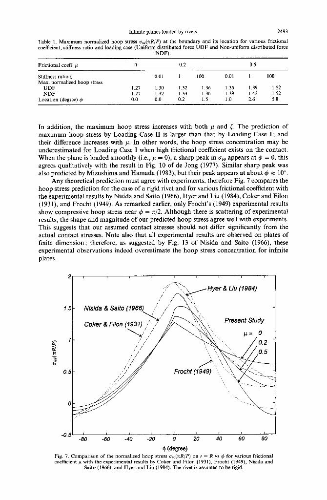
Any theoretical prediction must agree with experiments, therefore Fig. 7 compares the hoop stress prediction for the case of a rigid rivet and for various frictional coefficient with the experimental results by Nisida and Saito (1966), Hyer and Liu (1984), Coker and Filon (1931), and Frocht (1949). As remarked earlier, only Frocht’s (1949) experimental results show compressive hoop stress near 4 = n/2. Although there is scattering of experimental results, the shape and magnitude of our predicted hoop stress agree well with experiments. This suggests that our assumed contact stresses should not differ significantly from the actual contact stresses. Note also that all experimental results are observed on plates of finite dimension ; therefore, as suggested by Fig. 13 of Nisida and Saito (1966), these experimental observations indeed overestimate the hoop stress concentration for infinite plates.
Hyer & Liu (1984)
I I -“‘5 -80
I I I t I I I I
-60 -40 -20 0 20 40 60 80
$ @wee) Fig. 7. Comparison of the normalized hoop stress a&nR/P) on r = R vs 4 for various frictional coefficient p with the experimental results by Coker and Filon (1931), Frocht (1949), Nisida and
Saito (1966), and Hyer and Liu (1984). The rivet is assumed to be rigid.

2494 K. C. Ho and K. T. Chau
------- radial stress shear stress
~ hoop stress ‘I_ --__ r/R= 1.1
-2 1 I I I I I I ! 1 -80 -60 -40 -20 0 20 40 60 80
Fig. 8. The normalized radial stress o,J(&R), shear stress r~J(foR) and hoop stress a,,/(faR) vs Q for various values of r/R. Only the results for Loading Case I are shown, and the following
parameters are used : [ = 1 and p = 0.2.
Conclusions for Figs 4-7 apply only to the contact stress at the boundary r = R. Figure 8 shows how the stress concentration decays with radial distance from the hole boundary, and only Loading Case I is shown for illustrative purpose. The rivet is assumed to have the same material properties of the plane with coefficient of friction p = 0.2. Figure 8 shows the normal stress a,,/(@), shear stress crJ(&R) and hoop stress aoo/(fbR) vs c$ for various values of r/R. As shown in Fig. 8, all these dimensionless stresses decay rapidly and smoothly with radial distance and become negligible for r/R 2 5.
5. CONCLUSION
We have derived analytically a closed-form solution for the stress concentration in an infinite plane loaded by a rivet of an arbitrarily different material. Unlike previous studies (e.g., Knight, 1935 ; Theocaris, 1956 ; Mori, 1972), the load carried by the rivet is modelled as distributed body forces, instead of a concentrated load at the centre of the rivet. Two body force potentials are introduced to model the cases of conservative, uniform distributed force shown in Fig. 2 (Loading Case I: UDF) and non-conservative, non-uniform dis- tributed force (Loading Case II : NDF) similar to those caused by shear force on a circular section shown in Fig. 3. Our results show that the normal contact stress on r = R decreases with stiffness ratio [ = pJ,u, (p, and pZ are the shear moduli for the plane and the rivet, respectively), but the shear contact stress increases with [. The normal contact stress for Loading Case I is larger than those for Loading Case II, while the shear contact stress for Loading Case I is smaller than those for Loading Case II. These differences are more apparent for higher value of frictional coefficient p between the plane and rivet. On the hole boundary, the hoop stress can, in general, be divided into a compressive zone (-n/2 < 4 < - 4,) and a tensile zone (- #i < 4 < 42). A typical value for 4, is from 60” to 70”. For the case of a rigid rivet with high-friction contact (e.g., p = 0.5 and c = loo), a second compressive zone appears near 4 = 742, this differs from all previous theoretical predictions (e.g., Bickley, 1928 ; Knight, 1935 ; Mizushima and Hamada, 1983). However,

Infinite planes loaded by rivets 2495
such a compressive zone near 4 = 71/2 was observed by Frocht (1949) using photoelastic method. The maximum normalized hoop stresses for a rigid rivet with p equal to 0,0.2 and 0.5 are 1.27, 1.36 and 1.52, respectively, by both Loading Cases I and II. Larger p and [ result in higher maximum hoop stress and the corresponding location of maximum hoop stress deviates farther from the point 4 = 0.
Although ad hoc assumptions have been made in obtaining the contact stresses, which depend on the material constants of both rivet and plane, and the frictional coefficient on the contact zone, our predictions are comparable to the experimental results by Coker and Filon (193 l), Frocht (1949), Nisida and Saito (1966) and Hyer and Liu (1984). This lends credence to the validity of the assumed contact stresses ; however, further experimental and theoretical studies are recommended. The extension of the present analysis to the problem of rivet action on an infinite strip will be an interesting study to be considered next. In particular, the alternating method of Howland (1928, 1930) and Howland and Stevenson (1933) may be used in such analysis.
Acknowledgements-This study was supported by The Hong Kong Polytechnic University Grant No. 0350-334- A3-310. The problem was inspired by a discussion with Prof. S. L. Chan.
REFERENCES
Bickley, W. G. (1928). The distribution of stress round a circular hole in a plate. Philosophy Trunsactions of the Royal Society, London A 221,383415.
Coker, E. G. and Filon, L. N. G. (1931). A Treatise on Photoelasticity, Cambridge University Press, Cambridge. Cox, H. L. and Brown, A. F. C. (1964). Stresses round pins in holes. Aeronautics Quarterly l&357-372. de Jong, Th. (1977). Stress around pin-loaded holes in elastically orthotropic or isotropic plates. Journal of
Computers and Materials 11, 313-33 1. Frocht, M. M. (1949). Photoelasticity, vol. 1, Wiley, New York. Frocht, M. M. and Hill, H. N. (1940). Stress-concentration factors around a central circular hole in a plate loaded
through pin in the hole. Transactions of ASME, Applied Mechanics 62, A-5-A-9. Gere, J. M. and Timsohenko, S. P. (1990). Mechanics of Materials, 3rd edn, PWS-KENT, Boston. Howland, R. C. J. (1928). Stress systems in an infinite strip. Philosophy Transactions of the Royal Society, London
A 124,89-l 19. Howland, R. C. J. (1930). On the stresses in the neighbourhood of a circular hole in a strip under tension.
Philosophy Transactions of the Royal Society, London A 229,49986. Howland, R. C. J. and Stevenson, A. C. (1933). Bi-harmonic analysis in a perforated strip. Philosophy Transactions
of the Royal Society, London A 232, 155-222. Hyer, M. W. and Klang, E. C. (1985). Contact stresses in pin-loaded orthotropic plates. International Journal of
Solids and Structures 21,957-975. Hyer, M. W., Klang, E. C. and Cooper, D. E. (1987). The effects of pin elasticity, clearance, and friction on the
stresses in a pin-loaded orthotropic plate. Journal of Computers and Materials 21, 19&206. Hyer, M. W. and Liu, D. (1984). Stresses in pin-loaded orthotropic plates using photoelasticity. NASA contractor
report, CR-172498, NASA, U.S.A. Jessop, H. T., Snell, C. and Holister, G. S. (1958). Photoelastic investigation on plates with single interference-fit
pins with load applied (a) to pin only and (b) to pin and plate simultaneously. Aeronautics Quarterly 9, 147- 163.
Karasudhi, P. (1991). Foundations of Solid Mechanics, Kluwer Academic Publishers, Dordrecht. Knight, R. C. (1935). The action of a rivet in a plate of finite breadth. Philosophy Magazine, Series 7 19, 517-540. Levy, S. and Smith, F. C. (1949). Stress distribution near reinforced circular hole loaded by pin. Journal of the
Research of the National Bureau Standards 42, 397404. Mizushima, I. and Hamada, M. (1983). Stress analysis around circular hole in infinite plate with rigid disk (case
of load applied to disk). Bulletin of the JSME 26, 12961301. Mori, K. (1972). Stress distributions in a semi-infinite plate with a row of circular holes. Bulletin of the JSME 15,
899-906. Nisida, M. and Saito, H. (1966). Stress distributions in a semi-infinite plate due to a pin determined by inter-
ferometric method. Experimental Mechanics 6,273-279. Noble, B. and Hussain, M. A. (1969). Exact solution of certain dual series for indentation and inclusion problems.
International Journal of Engineering Science 7, 114991161. Peterson, R. E. (1974). Stress Concentration Factors, Wiley, New York. Prudnikov, A. P., Brychkov, Y. A. and Marichev, 0. I. (1986). Integrals and Series, Vol. 1 : Elementary Functions,
translated from the Russian by Queen, N. M., Gordon and Breach Science Publishers, New York. Rao, A. K. (1978). Elastic analysis of pin joints. Computers and Structures 9, 125-144. Ryder, G. H. (1988). Strength of Materials, 3rd edn, ELBS/Macmillan. Theocaris, P. S. (1956). The stress distribution in a strip loaded in tension by means of a central pin. Transactions
of ASME, Applied Mechanics 78, 85590. Timoshenko, S. P. and Goodier, J. N. (1970). Theory of Elasticity, 3rd edn, McGraw-Hill, New York.

2496 K. C. Ho and K. T. Chau
APPENDIX
The following equations for infinite sums are obtained from Prudnikov ef al. (1986). Each formula has been checked numerically ; we found some minor typos in the formulas we used, thus, corrections have been made to the original equations before they are reported below. The following formulas are adopted from eqns (7) and (14) of Section 54.9 of Prudnikov et al. (1986) for Irl < 1 and 0 < x < 27~:
&Gi cosnx = $bos;tanhh’ [$cos I]+ sin:tan-’ [gsint]} (Al)
sinnx =*{cosGtan~’ [gsin:]- sinitanh-’ [gcost]}
.%& cosnx =${cos;tanh-’ [gcosg]- sin;tan~’ [gsint]}-
sinnx = \:.jc*s;tan-’ [gsin:]+ sin;tanhh’ [gcost]}.
After some minor corrections to eqn (6) of Section 5.4.9 of Prudnikov et al. (1986) for Irl < 1, we have :
_ $“+I c-
1 2r sin x .=,2n+ 1
sin(2n+1)x = ?tan~’ - [ 1 l-r2
;c +t,
c-- 1
.,02n+l cos(2n+ 1)x = ytanh-1
(-42)
(A3)
(A4)
(‘46)
Substitution of (27) into (26) and expansion of the resulting coefficients into partial fractions, then (Al) to (A6) above can be applied to obtain (28) given in the text. A similar procedure also applies to Loading Case II considered in Section 3.2.