an integral quality monitoring system for real-time...
TRANSCRIPT

An integral quality monitoring system for real-time verification of intensitymodulated radiation therapy
Mohammad K. Islama�
Department of Radiation Physics, Radiation Medicine Program, Princess Margaret Hospital, Toronto,Ontario M5G 2M9, Canada; Department of Radiation Oncology, University of Toronto, Toronto,Ontario M5G 2M9, Canada; and Institute of Biomaterials and Biomedical Engineering,University of Toronto, Toronto, Ontario M5S 2Z9, Canada
Bernhard D. Norrlinger and Jason R. SmaleDepartment of Radiation Physics, Radiation Medicine Program, Princess Margaret Hospital, Toronto,Ontario M5G 2M9, Canada
Robert K. HeatonDepartment of Radiation Physics, Radiation Medicine Program, Princess Margaret Hospital, Toronto,Ontario M5G 2M9, Canada and Department of Radiation Oncology, University of Toronto, Toronto,Ontario M5G 2M9, Canada
Duncan GalbraithDepartment of Radiation Physics, Radiation Medicine Program, Princess Margaret Hospital, Toronto,Ontario M5G 2M9, Canada
Cary FanInstitute of Biomaterials and Biomedical Engineering, University of Toronto, Toronto, Ontario M5S 2Z9,Canada
David A. JaffrayDepartment of Radiation Physics, Radiation Medicine Program, Princess Margaret Hospital, Toronto,Ontario M5G 2M9, Canada; Department of Medical Biophysics, University of Toronto, Toronto,Ontario M4N 3M5, Canada; and Department of Radiation Oncology, University of Toronto, Toronto,Ontario M5G 2M9, Canada
�Received 14 March 2009; revised 24 September 2009; accepted for publication 25 September 2009;published 5 November 2009�
Purpose: To develop an independent and on-line beam monitoring system, which can validate theaccuracy of segment-by-segment energy fluence delivery for each treatment field. The system isalso intended to be utilized for pretreatment dosimetric quality assurance of intensity modulatedradiation therapy �IMRT�, on-line image-guided adaptive radiation therapy, and volumetric modu-lated arc therapy.Methods: The system, referred to as the integral quality monitor �IQM�, utilizes an area integratingenergy fluence monitoring sensor �AIMS� positioned between the final beam shaping device �i.e.,multileaf collimator �MLC�� and the patient. The prototype AIMS consists of a novel spatiallysensitive large area ionization chamber with a gradient along the direction of the MLC motion. Thesignal from the AIMS provides a simple output for each beam segment, which is compared in realtime to the expected value. The prototype ionization chamber, with a physical area of22�22 cm2, has been constructed out of aluminum with the electrode separations varying linearlyfrom 2 to 20 mm. A calculation method has been developed to predict AIMS signals based on anelementwise integration technique, which takes into account various predetermined factors, includ-ing the spatial response function of the chamber, MLC characteristics, beam transmission throughthe secondary jaws, and field size factors. The influence of the ionization chamber on the beam hasbeen evaluated in terms of transmission, surface dose, beam profiles, and depth dose. The sensitiv-ity of the system was tested by introducing small deviations in leaf positions. A small set of IMRTfields for prostate and head and neck plans was used to evaluate the system. The ionization chamberand the data acquisition software systems were interfaced to two different types of linear accelera-tors: Elekta Synergy and Varian iX.Results: For a 10�10 cm2 field, the chamber attenuates the beam intensity by 7% and 5% for 6and 18 MV beams, respectively, without significantly changing the depth dose, surface dose, anddose profile characteristics. An MLC bank calibration error of 1 mm causes the IQM signal of a3�3 cm2 aperture to change by 3%. A positioning error in a single 5 mm wide leaf by 3 mm in3�3 cm2 aperture causes a signal difference of 2%. Initial results for prostate and head and neckIMRT fields show an average agreement between calculation and measurement to within 1%, witha maximum deviation for each of the smallest beam segments to within 5%. When the beam
segments of a prostate IMRT field were shifted by 3 mm from their original position, along the5420 5420Med. Phys. 36 „12…, December 2009 0094-2405/2009/36„12…/5420/9/$25.00 © 2009 Am. Assoc. Phys. Med.

5421 Islam et al.: Real-time verification of IMRT 5421
direction of the MLC motion, the IQM signals varied, on average, by 2.5%.Conclusions: The prototype IQM system can validate the accuracy of beam delivery in real time bycomparing precalculated and measured AIMS signals. The system is capable of capturing errors inMLC leaf calibration or malfunctions in the positioning of an individual leaf. The AIMS does notsignificantly alter the beam quality and therefore could be implemented without requiring recom-missioning measurements. © 2009 American Association of Physicists in Medicine.�DOI: 10.1118/1.3250859�
Key words: IMRT, real-time quality assurance, on-line treatment verification, IGART, large areaionization chamber
I. INTRODUCTION
In recent years the practice of radiation therapy �RT� hasbeen going through rapid advancements with the potential ofimproving treatment outcomes. These advances can be attrib-uted to innovations in treatment planning and delivery suchas intensity modulated radiation therapy �IMRT�,1,2 the avail-ability of high quality imaging modalities3,4 for both targetvolume definition �computed tomography, positron emissiontomography, and magnetic resonance imaging� and treatmentsetup verification �electronic portal imaging devices and ki-lovolt cone beam computed tomography�. These innovations,coupled with the rapid progress in information technologies,have revolutionized the RT field. However, these develop-ments have led to a more complex and less intuitive planningand treatment delivery process: Multidisciplinary teams nowdevelop plans utilizing multiple imaging modalities to definetarget volumes in three and four dimensions �including timeevolution�; computer-assisted optimization software devisesintensity modulated beams; and the synchronization of dy-namic multileaf collimator �MLC� motion, variable doserate, and gantry angle �the recently introduced volumetricmodulated arc therapy �VMAT�� form the actual treatmentdelivery. Moreover, the entire process of RT utilizes multiplesoftware systems, often provided by different vendors. Theincreased complexities in treatment planning, delivery, andthe overall process have created enormous quality assurance�QA� challenges for modern radiation therapy. Presently, pre-treatment IMRT QA tasks are performed by employing con-ventional dosimetry tools in a fragmentary manner, involvingmany staff and machine hours.5–8 The QA is performed onlyprior to the first of many �30–40� treatment sessions; treat-ment delivery errors that may be introduced in subsequentsessions could go undetected. Common mistreatments mayinvolve human errors as well as errors in software and hard-ware due to malfunctions or as a result of system upgrades.No comprehensive QA solution is available to meet the com-plexities associated with the modern radiation therapy pro-cess and challenges associated with the emerging technolo-gies such as on-line image-guided adaptive radiation therapy�IGART� and VMAT. An efficient and independent on-linebeam monitoring system could play an important role inmeeting the needs of modern and upcoming RT QA practice.
The concept of an on-line and independent beam deliverymonitor was first introduced by Paliwal et al.9 for noncom-
puterized linear accelerators �linacs�. The authors demon-Medical Physics, Vol. 36, No. 12, December 2009
strated the usefulness of a large area monitor chamber,mounted on the shielding tray, for checking the daily con-stancy of treatment delivery. Poppe et al.10 described a novelmethod of monitoring the constancy of IMRT beam deliveryby using a multiwire large area ionization chamber, mountedon the shielding tray, which functioned like an array of linedetectors intercepting radiation fluence along the length ofeach MLC leaf pair. An on-line dosimetry system,COMPASS®, has been recently released commercially byIBA Dosimetry, Uppsala, Sweden. The system consists of amatrix of 40�40 small ionization chambers, mounted justbelow the collimator, to capture the beam fluence map. Thefluence maps are utilized to calculate the actual dose deliv-ered to the patient’s anatomy using the system’s treatmentplanning software. The COMPASS® system can be used forpretreatment plan QA, as well as for on-line verification oftreatment delivery. We have developed a simple alternativeenergy fluence verification system, which can verify the ac-curacy and consistency of beam delivery during each treat-ment session.
II. MATERIALS AND METHODS
The goal of this work was to develop an independentdosimetry system, which can validate the accuracy of energyfluence in real time with minimal user interaction. This re-quires a beam monitoring detector that encompasses the en-tire radiation field, has robust and stable performance, andprovides a spatially sensitive signal in terms of a simpleoutput. To fulfill these criteria, a large area radiation detectorwas designed to be mounted below the MLC. The detectorgenerates a spatially sensitive integral signal, or more pre-cisely, a spatially sensitive dose-area product, for each beamsegment. Based on precalculated or reference measurementvalues, the system is capable of validating the accuracy ofthe beam delivery in real time.
The prototype verification system, referred to as the inte-gral quality monitor �IQM�, consists of two key components:�1� An area integrating energy fluence monitoring sensor�AIMS� and �2� a calculation module, IQM_CALC. The mea-sured signal from the AIMS for each beam segment is com-pared on-line to the precalculated value to verify the accu-racy of the treatment delivery. The expected signal iscalculated by IQM_CALC based on the field information de-rived directly from the treatment planning system �TPS� and
is independent of the treatment delivery systems, i.e., the
5422 Islam et al.: Real-time verification of IMRT 5422
record-and-verify system and the linac control system. Theprocess flow of the IQM system is illustrated in Fig. 1.
II.A. Area integrating energy fluence monitoringsensor
The AIMS is composed of a spatially sensitive large areaionization chamber and a dosimetry system incorporating awide dynamic range electrometer. For the prototype system,a one-dimensional spatial variation in the chamber sensitivitywas investigated to capture aperture errors due to errors inMLC leaf positions. By angling the polarizing electrodesrelative to the collector, a position varying electrode separa-tion across the chamber was created, which consequentlyprovided a spatially variable sensitivity �Fig. 2�a��. Thechamber was mounted such that the slope of ion chamberseparation was parallel to the direction of MLC leaf motion.
The prototype ion chamber was designed for both me-chanical and dosimetric stability to monitor an area largeenough to fully encompass typical IMRT beams and to gen-erate a clinically useful spatially sensitive signal through areasonable selection of polarizing electrode slope. Chambercomponents were constructed from aluminum �alloy 6061�with a sensitive area of 22�22 cm2; when mounted at thelinac collimator face, the chamber can monitor a radiationfield that projects to a size of approximately 34�34 cm2 atthe isocenter. The outer polarizing plates were 3.18 mm �1/8in.� thick, while the inner collector plate was 1.59 mm �1/16in.� thick, with the larger outer plate thickness chosen forstructural rigidity. During the initial design, it was assumed
FIG. 1. Schematic diagram showing the process flow for the IQM system. Ta calculation program, IQM_CALC. The IQM MANAGER �software system� cosegment-by-segment basis. The eavesdrop data tap allows the IQM system tpatient data from the record-and-verify system to the linac.
that the spatial sensitivity of the chamber would be propor-
Medical Physics, Vol. 36, No. 12, December 2009
tional to the electrode plate separation �assuming a constantcollection efficiency� and thus proportional to the plate slope.Although a higher plate slope would produce a larger spatialsensitivity, a trade-off was necessary to keep the overallchamber thickness to a practical size. The slope of the plateseparation was chosen to produce a change in response ofapproximately 0.5% mm−1 near the center of the chamberalong the gradient. The total separation between the highvoltage polarizing electrodes varied linearly from 2 to 20
stem consists of a large area energy fluence monitoring sensor �AIMS� andes the signal from the detector with the precalculated expected value on aomatically capture the selected patient’s name and ID during the transfer of
Aluminum
PMMA
InsulatorGuardElectrode
CollectorElectrode
PolarizingElectrode(a)
Integrator B
Integrator AADC A
ADC B
Microprocessor
cMU Counter(optional)
16:1 Mux B
3 MSB toNOR B
16:1 Mux A
3 MSB toNOR AIon
ChamberInput
(b)
FIG. 2. �a� Schematic diagram of the prototype spatially sensitive large area�22�22 cm2� ionization chamber; outer electrode �polarizing electrode�separations vary linearly from 2 to 20 mm. �b� Functional block diagram ofthe dosimetry system, which includes a wide dynamic range dual integratorelectrometer and a microprocessor. The microprocessor controls the integra-
he symparo aut
tion and readout of signals in synchronization with beam segments.
s, rec
5423 Islam et al.: Real-time verification of IMRT 5423
mm across the chamber, as shown in Fig. 2�a�. The sensitivevolume of the ion chamber was approximately 530 cm3.
Electrode plate separation and orientation were main-tained by an insulating frame of machined polymethyl meth-acrylate �PMMA�. A guard electrode at the same potential asthe collector was formed from a continuous aluminum chan-nel embedded within the PMMA frame, which supported thecollector electrode and intercepted leakage currents betweenthe high voltage and the collector electrodes. The guard andcollector electrodes were maintained at ground potential witha polarizing potential of 500 V applied to the high voltageelectrodes during normal operation.
The overall thickness of the prototype ion chamber wasapproximately 4 cm. The chamber was mounted at theshielding tray of an Elekta linac and at the wedge tray ofVarian linac. The distance between the face of the collimatorand the bottom of the chamber was 7.5 cm for the Elektalinac, while a distance of 6.5 cm was achieved between thewedge tray slot and the bottom of the chamber for the Varianlinac.
Standard commercially available electrometers are typi-cally unable to integrate the charge from a large volume ionchamber without saturating. While it is possible to design anelectrometer that can integrate a large charge, readout accu-racy and resolution for small charge readings are often com-promised. We have developed a unique wide dynamic rangeelectrometer based dosimetry system that overcomes theseproblems by using dual electrometers operating in a switch-ing configuration �Fig. 2�b��. Each electrometer is of the fa-miliar integrating capacitor type. The dual integrator input
PrimaryCollimator
SecondaryCollimator
MultileafCollimator
IQMChamber
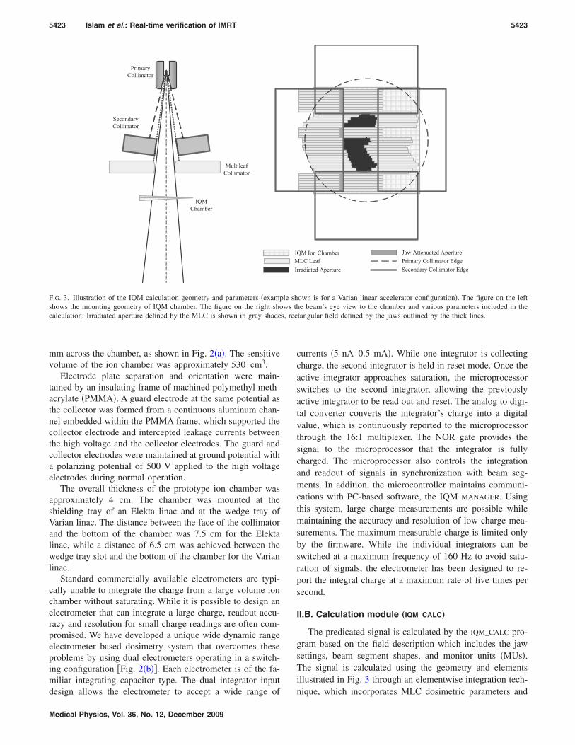
FIG. 3. Illustration of the IQM calculation geometry and parameters �exampshows the mounting geometry of IQM chamber. The figure on the right shocalculation: Irradiated aperture defined by the MLC is shown in gray shade
design allows the electrometer to accept a wide range of
Medical Physics, Vol. 36, No. 12, December 2009
currents �5 nA–0.5 mA�. While one integrator is collectingcharge, the second integrator is held in reset mode. Once theactive integrator approaches saturation, the microprocessorswitches to the second integrator, allowing the previouslyactive integrator to be read out and reset. The analog to digi-tal converter converts the integrator’s charge into a digitalvalue, which is continuously reported to the microprocessorthrough the 16:1 multiplexer. The NOR gate provides thesignal to the microprocessor that the integrator is fullycharged. The microprocessor also controls the integrationand readout of signals in synchronization with beam seg-ments. In addition, the microcontroller maintains communi-cations with PC-based software, the IQM MANAGER. Usingthis system, large charge measurements are possible whilemaintaining the accuracy and resolution of low charge mea-surements. The maximum measurable charge is limited onlyby the firmware. While the individual integrators can beswitched at a maximum frequency of 160 Hz to avoid satu-ration of signals, the electrometer has been designed to re-port the integral charge at a maximum rate of five times persecond.
II.B. Calculation module „IQM_CALC…
The predicated signal is calculated by the IQM_CALC pro-gram based on the field description which includes the jawsettings, beam segment shapes, and monitor units �MUs�.The signal is calculated using the geometry and elementsillustrated in Fig. 3 through an elementwise integration tech-
rradiated Aperture
Jaw Attenuated ApertureLC Leaf Primary Collimator Edge
Secondary Collimator Edge
QM Ion Chamber
own is for a Varian linear accelerator configuration�. The figure on the lefte beam’s eye view to the chamber and various parameters included in the
tangular field defined by the jaws outlined by the thick lines.
IMI
le shws th
nique, which incorporates MLC dosimetric parameters and
5424 Islam et al.: Real-time verification of IMRT 5424
the spatial response of the chamber. The predicted AIMSsignal SCalc is given by
SCalc = MU · K · AOF�X,Y� · ��A1
F�x,y���x,y�dxdy
+ �A−A1
TMLC�x,y�F�x,y���x,y�dxdy
+ �R−A
TJaw�x,y�TMLC�x,y�F�x,y���x,y�dxdy� ,
�1�
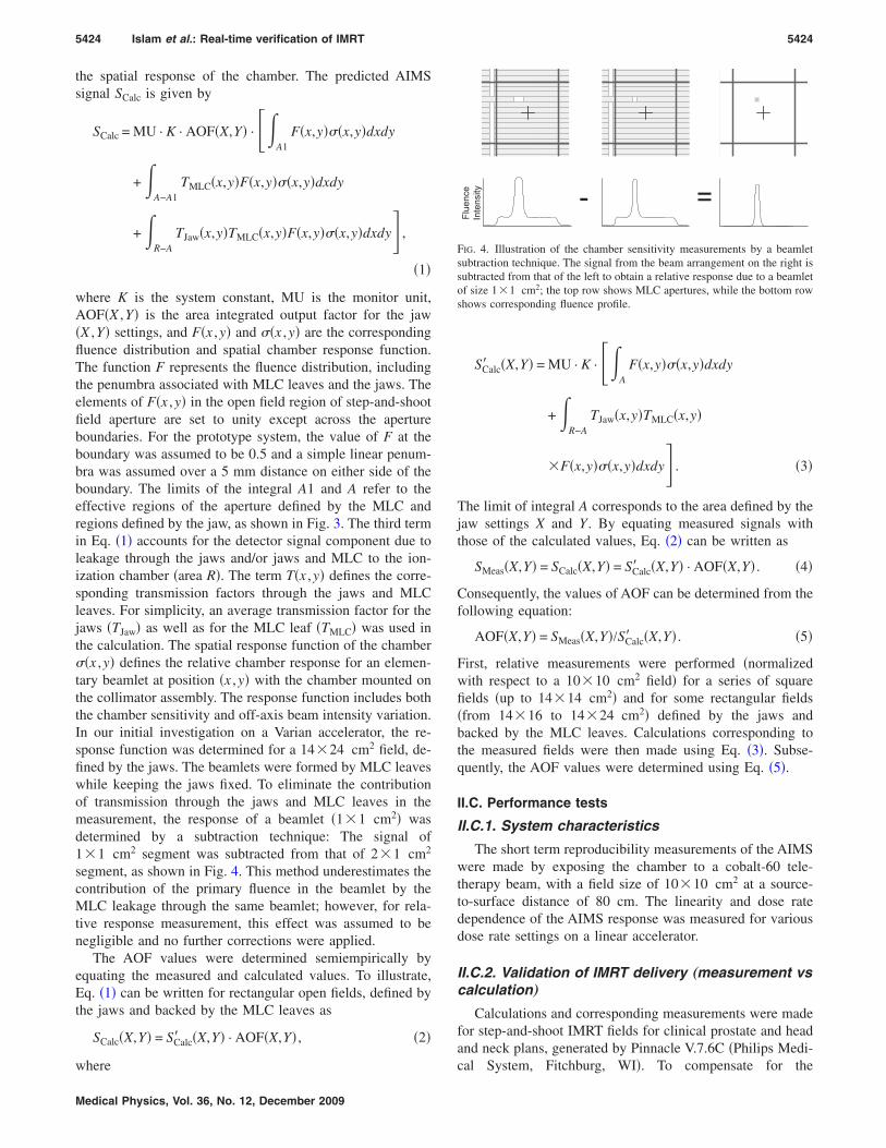
where K is the system constant, MU is the monitor unit,AOF�X ,Y� is the area integrated output factor for the jaw�X ,Y� settings, and F�x ,y� and ��x ,y� are the correspondingfluence distribution and spatial chamber response function.The function F represents the fluence distribution, includingthe penumbra associated with MLC leaves and the jaws. Theelements of F�x ,y� in the open field region of step-and-shootfield aperture are set to unity except across the apertureboundaries. For the prototype system, the value of F at theboundary was assumed to be 0.5 and a simple linear penum-bra was assumed over a 5 mm distance on either side of theboundary. The limits of the integral A1 and A refer to theeffective regions of the aperture defined by the MLC andregions defined by the jaw, as shown in Fig. 3. The third termin Eq. �1� accounts for the detector signal component due toleakage through the jaws and/or jaws and MLC to the ion-ization chamber �area R�. The term T�x ,y� defines the corre-sponding transmission factors through the jaws and MLCleaves. For simplicity, an average transmission factor for thejaws �TJaw� as well as for the MLC leaf �TMLC� was used inthe calculation. The spatial response function of the chamber��x ,y� defines the relative chamber response for an elemen-tary beamlet at position �x ,y� with the chamber mounted onthe collimator assembly. The response function includes boththe chamber sensitivity and off-axis beam intensity variation.In our initial investigation on a Varian accelerator, the re-sponse function was determined for a 14�24 cm2 field, de-fined by the jaws. The beamlets were formed by MLC leaveswhile keeping the jaws fixed. To eliminate the contributionof transmission through the jaws and MLC leaves in themeasurement, the response of a beamlet �1�1 cm2� wasdetermined by a subtraction technique: The signal of1�1 cm2 segment was subtracted from that of 2�1 cm2
segment, as shown in Fig. 4. This method underestimates thecontribution of the primary fluence in the beamlet by theMLC leakage through the same beamlet; however, for rela-tive response measurement, this effect was assumed to benegligible and no further corrections were applied.
The AOF values were determined semiempirically byequating the measured and calculated values. To illustrate,Eq. �1� can be written for rectangular open fields, defined bythe jaws and backed by the MLC leaves as
SCalc�X,Y� = SCalc� �X,Y� · AOF�X,Y� , �2�
where
Medical Physics, Vol. 36, No. 12, December 2009
SCalc� �X,Y� = MU · K · ��A
F�x,y���x,y�dxdy
+ �R−A
TJaw�x,y�TMLC�x,y�
�F�x,y���x,y�dxdy� . �3�
The limit of integral A corresponds to the area defined by thejaw settings X and Y. By equating measured signals withthose of the calculated values, Eq. �2� can be written as
SMeas�X,Y� = SCalc�X,Y� = SCalc� �X,Y� · AOF�X,Y� . �4�
Consequently, the values of AOF can be determined from thefollowing equation:
AOF�X,Y� = SMeas�X,Y�/SCalc� �X,Y� . �5�
First, relative measurements were performed �normalizedwith respect to a 10�10 cm2 field� for a series of squarefields �up to 14�14 cm2� and for some rectangular fields�from 14�16 to 14�24 cm2� defined by the jaws andbacked by the MLC leaves. Calculations corresponding tothe measured fields were then made using Eq. �3�. Subse-quently, the AOF values were determined using Eq. �5�.
II.C. Performance tests
II.C.1. System characteristics
The short term reproducibility measurements of the AIMSwere made by exposing the chamber to a cobalt-60 tele-therapy beam, with a field size of 10�10 cm2 at a source-to-surface distance of 80 cm. The linearity and dose ratedependence of the AIMS response was measured for variousdose rate settings on a linear accelerator.
II.C.2. Validation of IMRT delivery „measurement vscalculation…
Calculations and corresponding measurements were madefor step-and-shoot IMRT fields for clinical prostate and headand neck plans, generated by Pinnacle V.7.6C �Philips Medi-
.
- =
Fluence
Intensity
FIG. 4. Illustration of the chamber sensitivity measurements by a beamletsubtraction technique. The signal from the beam arrangement on the right issubtracted from that of the left to obtain a relative response due to a beamletof size 1�1 cm2; the top row shows MLC apertures, while the bottom rowshows corresponding fluence profile.
cal System, Fitchburg, WI�. To compensate for the

5425 Islam et al.: Real-time verification of IMRT 5425
overshoot/undershoot phenomenon11 of dose delivery onVarian units due to the communication delay between theMLC controller and the dosimetry system, the centi-MU�cMU� count available from the console dose rate integratingboard was utilized. All the results presented for Varian step-and-shoot IMRT have been normalized with respect to thecorresponding cMU counts.
II.C.3. IQM response reproducibility „constancy ofIMRT delivery…
Repeated measurements were performed for a number ofclinical IMRT fields over several days to assess the reproduc-ibility of IQM response. These measurements were alsomade simultaneously with a Mapcheck detector array �SunNuclear Corporation, Melbourne, FL� to verify consistentfield delivery. The effect of linac output variation on the IQMchamber signal was corrected using the average Mapchecksignal. The Mapcheck system has been shown to achieve along term reproducibility12 within 0.5%.
II.C.4. IQM performance for simulated errors „MLCleaf errors…
To evaluate the sensitivity of the IQM system in terms ofcapturing common error conditions, comparative measure-ments were made for a small sample of MLC defined fields.Measurements were performed on a Varian linear accelerator,equipped with a 120-leaf Millennium MLC for a set of stan-dard fields and subsequently for the same fields with delib-erate errors in the MLC leaf positions. The chamber gradientwas parallel to the direction of the MLC leaf motions.
II.D. Influence of chamber on the beam
The influence of the ionization chamber on the beams wasassessed in terms of beam attenuation, change in surfacedose, and change in beam quality �percent depth dose andprofiles�.
III. RESULTS
III.A. Parameters for the IQM_CALC
The spatial response function ��x ,y� for the large areachamber for 14�24 cm2 jaw defined field is shown in Fig.5. The response values were normalized at the center of thechamber. The change in the relative sensitivity was found tobe approximately 0.55% mm−1 at the center of the chamber,with some variation along the gradient due to changing elec-trode separations. Along the symmetry axis, at �6.0 cm off-axis distances �corresponding to larger/smaller plate separa-tions�, the sensitivity values were 0.36% mm−1 and1.1% mm−1, respectively. In the nongradient direction, thesensitivity varied along the off-axis direction very slowly, asexpected. The rapid fall off of the sensitivity at points closeto the edge of the chamber is attributed to the loss of elec-trons into the chamber walls.
The AOF values for 6 MV beams are shown in Fig. 6.
These values were utilized in the IQM_CALC program; forMedical Physics, Vol. 36, No. 12, December 2009
rectangular fields, the AOF values were determined using anequivalent square formula.13
III.B. Performance tests
III.B.1. System characteristics
The combined ion chamber and electrometer system wasfound to be stable and reproducible, and highly linear in doseresponse. The readings of the electrometer with a field sizeof 10�10 cm2 for ten consecutive measurements werefound to be highly reproducible, with a standard deviation of0.08%. The linearity of the chamber response was measuredover a wide range of 1–2000 MU. The signal vs MU showeda highly linear correlation with a R2 value of 0.999. The doserate dependence of the system’s response in the range of100–600 MU/min was found to be within 0.2%. Signal satu-ration was avoided due to the dual integrator configuration ofthe electrometer.
-10-5
05
10
0.6
0.8
1.0
1.2
1.4
1.6
-10
-5
05
10
RelativeSensitivity
Cross-Plane(cm)
In-Plane(cm)
FIG. 5. The spatial response function ��x ,y� of the chamber for a jaw set-ting of 14�24 cm2. The response values are normalized with respect to thevalue at the beam central axis. The in plane and cross plane dimensions referto the directions along and perpendicular to the MLC leaf motions,respectively.
5 10 15 20
0.96
0.98
1.00
1.02
1.04
AOF
Side of square field (cm)
FIG. 6. The AOF as a function of square and equivalent square fields for 6MV beams. The open circle represent data for square fields and the dia-monds represent data for equivalent squares of the rectangular fields. The
solid line represents a polynomial fit function of the data.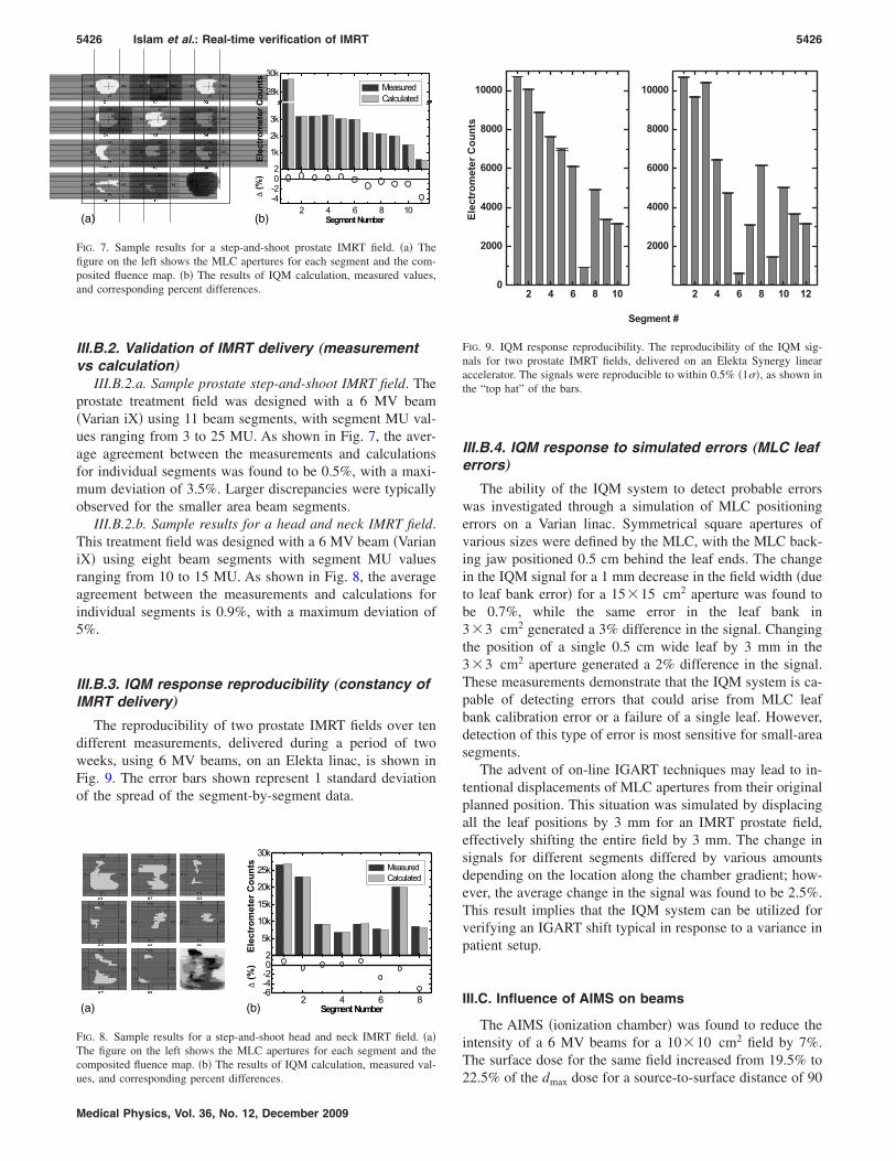
5426 Islam et al.: Real-time verification of IMRT 5426
III.B.2. Validation of IMRT delivery „measurementvs calculation…
III.B.2.a. Sample prostate step-and-shoot IMRT field. Theprostate treatment field was designed with a 6 MV beam�Varian iX� using 11 beam segments, with segment MU val-ues ranging from 3 to 25 MU. As shown in Fig. 7, the aver-age agreement between the measurements and calculationsfor individual segments was found to be 0.5%, with a maxi-mum deviation of 3.5%. Larger discrepancies were typicallyobserved for the smaller area beam segments.
III.B.2.b. Sample results for a head and neck IMRT field.This treatment field was designed with a 6 MV beam �VarianiX� using eight beam segments with segment MU valuesranging from 10 to 15 MU. As shown in Fig. 8, the averageagreement between the measurements and calculations forindividual segments is 0.9%, with a maximum deviation of5%.
III.B.3. IQM response reproducibility „constancy ofIMRT delivery…
The reproducibility of two prostate IMRT fields over tendifferent measurements, delivered during a period of twoweeks, using 6 MV beams, on an Elekta linac, is shown inFig. 9. The error bars shown represent 1 standard deviationof the spread of the segment-by-segment data.
X1 X2
Y1
Y2
X1 X2
Y1
Y2
X1 X2
Y1
Y2
X1 X2
Y1
Y2
X1 X2
Y1
Y2
X1 X2
Y1
Y2
X1 X2
Y1
Y2
X1 X2
Y1
Y2
X1 X2
Y1
Y2
X1 X2
Y1
Y2
X1 X2
Y1
Y2
2 4 6 8 10-4-202
1k
2k
3k
28k
30k
ElectrometerCounts
MeasuredCalculated
∆(%)
SegmentNumber(b)(a)
FIG. 7. Sample results for a step-and-shoot prostate IMRT field. �a� Thefigure on the left shows the MLC apertures for each segment and the com-posited fluence map. �b� The results of IQM calculation, measured values,and corresponding percent differences.
2 4 6 8-6-4-202
5k
10k
15k
20k
25k
30k
Electrom
eterCounts Measured
Calculated
∆(%)
SegmentNumber
02 0301
04 0605
07 08
(b)(a)
FIG. 8. Sample results for a step-and-shoot head and neck IMRT field. �a�The figure on the left shows the MLC apertures for each segment and thecomposited fluence map. �b� The results of IQM calculation, measured val-
ues, and corresponding percent differences.Medical Physics, Vol. 36, No. 12, December 2009
III.B.4. IQM response to simulated errors „MLC leaferrors…
The ability of the IQM system to detect probable errorswas investigated through a simulation of MLC positioningerrors on a Varian linac. Symmetrical square apertures ofvarious sizes were defined by the MLC, with the MLC back-ing jaw positioned 0.5 cm behind the leaf ends. The changein the IQM signal for a 1 mm decrease in the field width �dueto leaf bank error� for a 15�15 cm2 aperture was found tobe 0.7%, while the same error in the leaf bank in3�3 cm2 generated a 3% difference in the signal. Changingthe position of a single 0.5 cm wide leaf by 3 mm in the3�3 cm2 aperture generated a 2% difference in the signal.These measurements demonstrate that the IQM system is ca-pable of detecting errors that could arise from MLC leafbank calibration error or a failure of a single leaf. However,detection of this type of error is most sensitive for small-areasegments.
The advent of on-line IGART techniques may lead to in-tentional displacements of MLC apertures from their originalplanned position. This situation was simulated by displacingall the leaf positions by 3 mm for an IMRT prostate field,effectively shifting the entire field by 3 mm. The change insignals for different segments differed by various amountsdepending on the location along the chamber gradient; how-ever, the average change in the signal was found to be 2.5%.This result implies that the IQM system can be utilized forverifying an IGART shift typical in response to a variance inpatient setup.
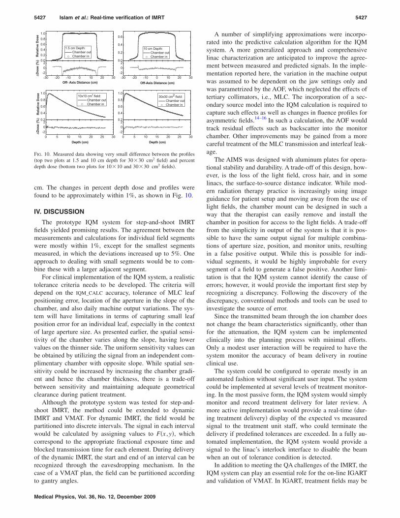
III.C. Influence of AIMS on beams
The AIMS �ionization chamber� was found to reduce theintensity of a 6 MV beams for a 10�10 cm2 field by 7%.The surface dose for the same field increased from 19.5% to
2 4 6 8 100
2000
4000
6000
8000
10000
ElectrometerCounts
Segment #
2 4 6 8 10 12
2000
4000
6000
8000
10000
FIG. 9. IQM response reproducibility. The reproducibility of the IQM sig-nals for two prostate IMRT fields, delivered on an Elekta Synergy linearaccelerator. The signals were reproducible to within 0.5% �1��, as shown inthe “top hat” of the bars.
22.5% of the dmax dose for a source-to-surface distance of 90
5427 Islam et al.: Real-time verification of IMRT 5427
cm. The changes in percent depth dose and profiles werefound to be approximately within 1%, as shown in Fig. 10.
IV. DISCUSSION
The prototype IQM system for step-and-shoot IMRTfields yielded promising results. The agreement between themeasurements and calculations for individual field segmentswere mostly within 1%, except for the smallest segmentsmeasured, in which the deviations increased up to 5%. Oneapproach to dealing with small segments would be to com-bine these with a larger adjacent segment.
For clinical implementation of the IQM system, a realistictolerance criteria needs to be developed. The criteria willdepend on the IQM_CALC accuracy, tolerance of MLC leafpositioning error, location of the aperture in the slope of thechamber, and also daily machine output variations. The sys-tem will have limitations in terms of capturing small leafposition error for an individual leaf, especially in the contextof large aperture size. As presented earlier, the spatial sensi-tivity of the chamber varies along the slope, having lowervalues on the thinner side. The uniform sensitivity values canbe obtained by utilizing the signal from an independent com-plimentary chamber with opposite slope. While spatial sen-sitivity could be increased by increasing the chamber gradi-ent and hence the chamber thickness, there is a trade-offbetween sensitivity and maintaining adequate geometricalclearance during patient treatment.
Although the prototype system was tested for step-and-shoot IMRT, the method could be extended to dynamicIMRT and VMAT. For dynamic IMRT, the field would bepartitioned into discrete intervals. The signal in each intervalwould be calculated by assigning values to F�x ,y�, whichcorrespond to the appropriate fractional exposure time andblocked transmission time for each element. During deliveryof the dynamic IMRT, the start and end of an interval can berecognized through the eavesdropping mechanism. In thecase of a VMAT plan, the field can be partitioned according
0.00.20.40.60.81.0
0.0
0.2
0.4
0.6
0.2
0.4
0.6
0.8
1.0
0.2
0.4
0.6
0.8
1.0
-30 -20 -10 0 10 20 30-202
-30 -20 -10 0 10 20 30-202
0 5 10 15 20 25 30-202
0 5 10 15 20 25 30-202
RelativeDose
1.5 cm Depth:Chamber outChamber in
10 cm Depth:Chamber outChamber in
RelativeDose
10x10 cm2 field:Chamber outChamber in
30x30 cm2 field:Chamber outChamber in
Off- Axis Distance (cm)
∆Dose(%)
Off-Axis Distance (cm)
Depth (cm)
∆Dose(%)
Depth (cm)
FIG. 10. Measured data showing very small difference between the profiles�top two plots at 1.5 and 10 cm depth for 30�30 cm2 field� and percentdepth dose �bottom two plots for 10�10 and 30�30 cm2 fields�.
to gantry angles.
Medical Physics, Vol. 36, No. 12, December 2009
A number of simplifying approximations were incorpo-rated into the predictive calculation algorithm for the IQMsystem. A more generalized approach and comprehensivelinac characterization are anticipated to improve the agree-ment between measured and predicted signals. In the imple-mentation reported here, the variation in the machine outputwas assumed to be dependent on the jaw settings only andwas parametrized by the AOF, which neglected the effects oftertiary collimators, i.e., MLC. The incorporation of a sec-ondary source model into the IQM calculation is required tocapture such effects as well as changes in fluence profiles forasymmetric fields.14–16 In such a calculation, the AOF wouldtrack residual effects such as backscatter into the monitorchamber. Other improvements may be gained from a morecareful treatment of the MLC transmission and interleaf leak-age.
The AIMS was designed with aluminum plates for opera-tional stability and durability. A trade-off of this design, how-ever, is the loss of the light field, cross hair, and in somelinacs, the surface-to-source distance indicator. While mod-ern radiation therapy practice is increasingly using imageguidance for patient setup and moving away from the use oflight fields, the chamber mount can be designed in such away that the therapist can easily remove and install thechamber in position for access to the light fields. A trade-offfrom the simplicity in output of the system is that it is pos-sible to have the same output signal for multiple combina-tions of aperture size, position, and monitor units, resultingin a false positive output. While this is possible for indi-vidual segments, it would be highly improbable for everysegment of a field to generate a false positive. Another limi-tation is that the IQM system cannot identify the cause oferrors; however, it would provide the important first step byrecognizing a discrepancy. Following the discovery of thediscrepancy, conventional methods and tools can be used toinvestigate the source of error.
Since the transmitted beam through the ion chamber doesnot change the beam characteristics significantly, other thanfor the attenuation, the IQM system can be implementedclinically into the planning process with minimal efforts.Only a modest user interaction will be required to have thesystem monitor the accuracy of beam delivery in routineclinical use.
The system could be configured to operate mostly in anautomated fashion without significant user input. The systemcould be implemented at several levels of treatment monitor-ing. In the most passive form, the IQM system would simplymonitor and record treatment delivery for later review. Amore active implementation would provide a real-time �dur-ing treatment delivery� display of the expected vs measuredsignal to the treatment unit staff, who could terminate thedelivery if predefined tolerances are exceeded. In a fully au-tomated implementation, the IQM system would provide asignal to the linac’s interlock interface to disable the beamwhen an out of tolerance condition is detected.
In addition to meeting the QA challenges of the IMRT, theIQM system can play an essential role for the on-line IGART
and validation of VMAT. In IGART, treatment fields may be
5428 Islam et al.: Real-time verification of IMRT 5428
changed on-line following imaging of the patient’s position-ing; therefore, some form of on-line QA will be necessary.The AIMS of the IQM system can be modified to have two-dimensional spatial sensitivity by including two ion cham-bers with their gradients orthogonal to each other �along andperpendicular to the direction of MLC motion� enabling thevalidation of an arbitrary shift in the beam aperture or acompletely new beam aperture selected from a library ofbeams. In VMAT mode the beam is delivered with variabledose rates and leaf speeds simultaneous to the gantry mo-tions. In combination with an independent gantry angle sen-sor, such as an inclinometer attached to the gantry structure,the IQM can be utilized for the verification of segment-by-segment VMAT treatment delivery accuracy.
V. CONCLUSION
We have developed a prototype independent beam moni-toring system for modern radiation therapy, which providessegment-by-segment verification of the beam delivery in realtime. The system consists of a large area ionization chamberwith a gradient in the electrode plate separation, mountedbelow the MLC, and a calculation algorithm to predict thesignal from the ionization chamber based on the field param-eter information received directly from the TPS. The signalfrom the ionization chamber provides a spatially dependentdose-area-product signal for each beam segment. Initial testresults evaluating IMRT field segments show an averageagreement between the measured and predicted IQM signalto within 1%. However, further investigation is required toevaluate the influence of the accepted variance in clinicaldelivery, including machine output, MLC leaf positions, jawpositions, and beam flatness on the IQM signal. These resultswould help establish appropriate tolerances for effectivemonitoring of treatment delivery.
ACKNOWLEDGMENTS
This work has been partially supported by the NaturalSciences and Engineering Research Council of Canada�NSERC Grant No. I2IJ340869-06�. The authors gratefullyacknowledge the contributions of Canming Huang and Gra-ham Wilson for computer programming support and Jurij
Ivanoski for help with measurements.Medical Physics, Vol. 36, No. 12, December 2009
a�Author to whom correspondence should be addressed. Electronic ad-dresses: [email protected] and [email protected];Fax: �416� 946 6566.
1S. Webb, “Optimizing the planning of intensity-modulated radiotherapy,”Phys. Med. Biol. 39�12�, 2229–2246 �1994�.
2A. L. Boyer and C. X. Yu, “Intensity-modulated radiation therapy withdynamic multileaf collimators,” Semin. Radiat. Oncol. 9�1�, 48–59�1999�.
3L. E. Antonuk, J. Yorkston, W. Huang, H. Sandler, J. H. Siewerdsen, andY. el-Mohri, “Megavoltage imaging with a large-area, flat-panel, amor-phous silicon imager,” Int. J. Radiat. Oncol., Biol., Phys. 36�3�, 661–672�1996�.
4D. A. Jaffray and J. H. Siewerdsen, “Cone-beam computed tomographywith a flat-panel imager: Initial performance characterization,” Med.Phys. 27�6�, 1311–1323 �2000�.
5J. S. Tsai, D. E. Wazer, M. N. Ling, J. K. Wu, M. Fagundes, T. DiPetrillo,B. Kramer, M. Koistinen, and M. J. Engler, “Dosimetric verification ofthe dynamic intensity-modulated radiation therapy of 92 patients,” Int. J.Radiat. Oncol., Biol., Phys. 40�5�, 1213–1230 �1998�.
6L. E. Reinstein, X. H. Wang, C. M. Burman, Z. Chen, R. Mohan, G.Kutcher, S. A. Leibel, and Z. Fuks, “A feasibility study of automatedinverse treatment planning for cancer of the prostate,” Int. J. Radiat. On-col., Biol., Phys. 40�1�, 207–214 �1998�.
7C. Burman, C. S. Chui, G. Kutcher, S. Leibel, M. Zelefsky, T. LoSasso, S.Spirou, Q. Wu, J. Yang, J. Stein, R. Mohan, Z. Fuks, and C. C. Ling,“Planning, delivery, and quality assurance of intensity-modulated radio-therapy using dynamic multileaf collimator: A strategy for large-scaleimplementation for the treatment of carcinoma of the prostate,” Int. J.Radiat. Oncol., Biol., Phys. 39�4�, 863–873 �1997�.
8I. J. Yeo, A. Beiki, Y. B. Cho, M. Heydarian, T. Zhang, and M. Islam,“EDR2 film dosimetry for IMRT verification using low-energy photonfilters,” Med. Phys. 31�7�, 1960–1963 �2004�.
9B. R. Paliwal, M. Zaini, T. McNutt, E. J. Fairbanks, and R. Kitchen, “Aconsistency monitor for radiation therapy treatments,” Med. Phys. 23�10�,1805–1807 �1996�.
10B. Poppe, C. Thieke, D. Beyer, R. Kollhoff, A. Djouguela, A. Ruhmann,K. C. Willborn, and D. Harder, “DAVID—A translucent multi-wire trans-mission ionization chamber for in vivo verification of IMRT and confor-mal irradiation techniques,” Phys. Med. Biol. 51�5�, 1237–1248 �2006�.
11G. Ezzell and S. Chungbin, “The overshoot phenomenon in step-and-shoot IMRT delivery,” J. Appl. Clin. Med. Phys. 2�3�, 138–147 �2001�.
12P. A. Jursinic and B. E. Nelms, “A 2-D diode array and analysis softwarefor verification of intensity modulated radiation therapy delivery,” Med.Phys. 30�5�, 870–879 �2003�.
13S. Kim, T. C. Zhu, and J. R. Palta, “An equivalent square formula fordetermining head scatter factors for rectangular field,” Med. Phys. 24�11�,1770–1774 �1997�.
14A. Ahnesjo, “Analytic modeling of flattening filters in photon therapybeams,” Med. Phys. 21�8�, 1227–1235 �1994�.
15J. Olofsson, D. Goerg, and M. Karlsson, “A widely tested model for headscatter influence on photon beam output,” Radiother. Oncol. 67, 225–238�2003�.
16S. Kim, J. R. Palta, and T. C. Zhu, “A generalized solution for the in-air
output factors for irregular fields,” Med. Phys. 25�9�, 1692–1701 �1998�.