an integration of electrical installations design of ... of electrical installations design...
TRANSCRIPT
Abstract— The purpose of this paper is to describe a method of
Integration of Electrical installations design dedicated to holistic approach of intelligent buildings in a sustainable virtual environment. Given the increasing complexity of durable built spaces, quality, cost, time and environment constraints, it is necessary to review the principles of classic design and product development. Significant improvements in the electrical installations design process can be achieved by integrating CAD and CAE models to work in perfect spirit of collaboration in achieving the original construction. The intelligent buildings design processes and electrical installations technologies use today, have varying degrees of success. It is commonly known that during electrical installations design process, engineers are using computer-aided graphics programs.
Keywords— Electrical Installations Design, Intelligent Sustainable Buildings; Collaborative and Integrated Design; Intelligent Energy Efficiency
I. BUILDINGS INTELLIGENT DESIGN he crucial growth accelerator for intelligent sustainable buildings is based on a multidisciplinary research for a
sustainable built environment. The solution to achieve a truly energy-efficient building is interoperability, which is developed when the associated components with a variety of systems, regardless of manufacturer, "talk to each other" and work together smoothly to full operational efficiency [1].
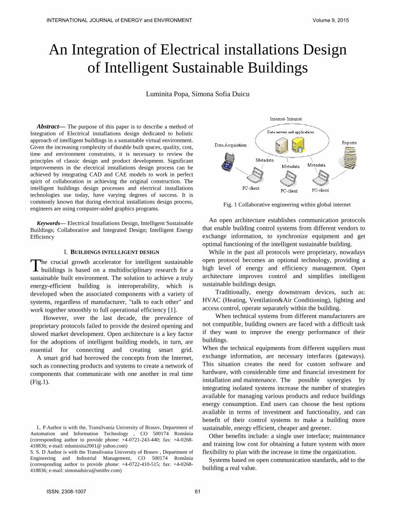
However, over the last decade, the prevalence of proprietary protocols failed to provide the desired opening and slowed market development. Open architecture is a key factor for the adoptions of intelligent building models, in turn, are essential for connecting and creating smart grid. A smart grid had borrowed the concepts from the Internet, such as connecting products and systems to create a network of components that communicate with one another in real time (Fig.1).
L. P.Author is with the, Transilvania University of Brasov, Department of
Automation and Information Technology , CO 500174 România (corresponding author to provide phone: +4-0721-243-440; fax: +4-0268-418836; e-mail: mluminita2001@ yahoo.com) S. S. D Author is with the Transilvania University of Brasov , Department of Engineering and Industrial Management, CO 500174 România (corresponding author to provide phone: +4-0722-410-515; fax: +4-0268-418836; e-mail: [email protected])
Fig. 1 Collaborative engineering within global internet
An open architecture establishes communication protocols
that enable building control systems from different vendors to exchange information, to synchronize equipment and get optimal functioning of the intelligent sustainable building.
While in the past all protocols were proprietary, nowadays open protocol becomes an optional technology, providing a high level of energy and efficiency management. Open architecture improves control and simplifies intelligent sustainable buildings design.
Traditionally, energy downstream devices, such as: HVAC (Heating, Ventilation&Air Conditioning), lighting and access control, operate separately within the building.
When technical systems from different manufacturers are not compatible, building owners are faced with a difficult task if they want to improve the energy performance of their buildings. When the technical equipments from different suppliers must exchange information, are necessary interfaces (gateways). This situation creates the need for custom software and hardware, with considerable time and financial investment for installation and maintenance. The possible synergies by integrating isolated systems increase the number of strategies available for managing various products and reduce buildings energy consumption. End users can choose the best options available in terms of investment and functionality, and can benefit of their control systems to make a building more sustainable, energy efficient, cheaper and greener.
Other benefits include: a single user interface; maintenance and training low cost for obtaining a future system with more flexibility to plan with the increase in time the organization.
Systems based on open communication standards, add to the building a real value.
An Integration of Electrical installations Design of Intelligent Sustainable Buildings
Luminita Popa, Simona Sofia Duicu
T
INTERNATIONAL JOURNAL of ENERGY and ENVIRONMENT Volume 9, 2015
ISSN: 2308-1007 61

II. SUTAINABLE INTELLIGENT BUILDING INTEGRATED DESIGN The concept of sustainable intelligent building design is the
result of a shared vision that tends to merge leading achievements in areas that involve the design and construction of buildings, areas usually considered separately. The most important of these areas include: external and internal architecture, construction technology in general, along with lighting, heating, ventilation, communication, computer, inland transport, security, ergonomic factors, etc.
The sustainable intelligent design features of building systems are as following:
- cooperation of all existing issues in the design process from conceptual design stage itself; - aggregation and cooperation of existing knowledge in the building design process from conceptual design stage itself;
- integration and cooperation of description and data representation models that must be unique and common in all phases of design, which means not only changing the interface; - building systems intelligence, which includes intelligent support for designer, intelligent interfaces, intelligent functions (knowledge base, inference capability that can understand the intentions of the designer, to detect errors, to suggest alternatives, to answer questions, etc.); the most important of these is the detection of errors that reduce design time and cost;
- reducing time error detection, increasing the accuracy of analysis or synthesis, reducing costs, particularly the maintenance costs.
Within this approach, project participants work is not sequential, but has a certain roundness, the date of return (to improve conception building) decisions of the previous stages. In the traditional approach, unconcerned with the building energy performance, a building designers are generally conduct their activities in a sequential manner: - Beginning of the design process, which is decisive for the final performance of the building, is made by architect without an assessment of the energy efficiency - Structure engineer makes their share starting from what the architect designed. - Engineers for building utilities/services (ventilation, heating / cooling, hot/cold water, electricity) bring their own contributions to the project, seeking to accommodate to the architect and structural engineers works. In this late phase is already too expensive to increase the energy performance of the building, other than minor changes to the architecture and strength.
Designing utilities / services is already influenced by the architecture and data structure of the building. Leeway for increasing energy efficiency of the building is limited, the energy calculation being more confirming than generating strategic decisions for building design. Right from the start, the architect works closely with at least one energy consultant. They are working with utilities engineer in an iterative mode to evaluate several options and to select the most optimal energy. An example of virtual cooperation
between building and construction department, HVAC design department and electrical design department is shown in Fig. 2.
Fig.2. Virtual cooperation between building and construction department, HVAC design department and electrical design
department
Starting from an initial proposal (eg. a given shape and orientation of the building, a particular shape and arrangement of windows, a specific structure of the walls and floors and a certain way of combining them, some basic ideas about building utilities /services, especially heating/cooling and ventilation installations) is doing the calculation of the annual energy required to operate the building.
Calculation returns to the starting point by performing some modifications, alleged beneficial and the energy is recalculated. The procedure is repeated for several options in order to select the optimal case
This iterative return for decisions modification of a previous stage is made in order to increase the energy performance of the building and can be done in several phases of the building design process
But it is generally recognized that decisions even in the early stages of conceptual design of the building, have the most significant impact on the building final energy performance.
In order to obtain maximum performance it is necessary to conduct an integrated design process in which the architect works from the very beginning together with a resistance engineer and a design engineer specializing in energy and climate control automation systems to optimize energy efficiency and building sustainability .
Thus, the traditional working teams are converting in virtual teams and operate to/from away from Headquarters in the so-called "workgroups sites".
INTERNATIONAL JOURNAL of ENERGY and ENVIRONMENT Volume 9, 2015
ISSN: 2308-1007 62
Virtual teams or workgroups are using tools and information and communication technologies (ICT) equipments.
III. ELECTRICAL INSTALLATIONS DESIGN Design stages:
1. Along with sharing dwg files from the team that handled the architectural plans, the electrical designer places the lighting receivers on architectural plans The lighting receivers.
The lighting system was integrated in the complex technical system of intelligent building. For each room is indicating its destination, type and number of luminaires and lamps power equips them, which is the connection phase and average illumination required. It is intended to avoid stroboscopic effect, glare and lighting sectorization by technological processes. The power receivers
We need to indicate the position of machinery, the switchboards and transformer and circuit routes and supply columns. For conductors, cables or rods we shall specify the type, section and method of layering.
2. Choose the general scheme of distribution for lighting and power. We have the next types of electrical diagrams: - Functional scheme (these are rendering using graphics the electrical installation principle of operation); - Wiring diagram (presented by conventional signs all circuits of electrical installations in order to understand the principle of operation); - Equivalent circuit (used to calculate a circuit or circuit element); - External, internal or terminal wiring scheme(useful for the implementation and verification of connections of an electrical installation).
3. Choose the position of the secondary switchboards. They will be placed in the center of gravity of the electric charge and easily accessible. Sub-distributor of power is available nearby receivers they serve, such as power circuit length does not exceed 50m for phase voltage 220V.
4. Choose the position of main and general switchboards. They will be placed in special arranged and heated (+ 15C) rooms, with natural ventilation and dry. For small consumers, the electric panels can be placed in interior niches with metal doors.
5. Distribute the receivers on circuits to balance load. 6. Choose the type of installation.
In the case of masonry walls, we are choosing a buried or apparent PVC conduit installation. In the case of unplastered concrete walls or prefabricated panels of civil buildings, wiring is posing in tubes or voids in the casting. For electrical installations in industrial buildings with unplastered walls we separate trails running conduit or armored cables.
7. Establish the electrical paths.
During this phase will take into account the other facilities - water, heating, sewer, gas, respecting the recommended distances to them. Electrical routes and points to avoid puncturing the pillars and resistance elements are also indicated on plans.
8. Calculate the elements and the light power plant. - Determine current account (by request) depending on the number and type of receivers; - Determining a starting currents (or top currents) according to the starting method;
Also in this phase should be designed and choosed the protection equipment and overload circuit. - Conductors or cables section shall be sized taking into account the heating effect and the maximum permissible heat.
9. Check conductors or cables section. Categories of checks to be made: - From the mechanical point of view (compared to the heating section sized to the minimum permissible constructive point of view); - When we have a loss of power (on the longest and loaded route, from the general panel to so far receiver); - At start (is done by comparing the current starting density with the maximum allowable values: 20 A / mm 2 for aluminum and 35 A / mm 2 for copper); - At the dynamic stability of the circuit (this last test is only carried out in bars installations). Also, check that the correct correlation of all compenent elements of the installation.
10. We choose the switching and measuring devices. This step is to choose the nominal current, in view of the fact that the switching devices need to have to withstand for a long time to calculate the current line and to provide thermal and dynamic stability of the short-circuit currents (ie, breaking the current must be greater than than the short-circuit current).
11. Draw the electrical details. Items that can be detailed: switchboards, routes through building elements, masking the centralized doses, etc.
12. Draw the economic side of the project. The cost of work is done by developing analytical estimates on physical stages and synthetic currency of items.
Documentation required for analytical estimates on physical stages include: - Anticipated measure; - List of functional and technological equipment for assembly, - Extracts of resources (materials, labor, construction equipment, small vehicles). Synthetic estimate of construction and assembly objects includes analytic totals rounded estimates that are part of the object.
Technical documentation The technical documentation accompanying the system throughout its existence, from conception phase, providing information on both the equipment and components to assembly, commissioning, operation and maintenance. Since documentation to be consulted by others, not only by its designer, the documentation should present as complete
INTERNATIONAL JOURNAL of ENERGY and ENVIRONMENT Volume 9, 2015
ISSN: 2308-1007 63
system to have a unified form as possible, to use a generally accepted language (terminology, rules of preparation and presentation documents), approved by designers, manufacturers and users.
So full documentation preparation involves the following steps: 1. Theme Design; 2. Prefeasibility Study; 3. Framework Content - written parts; 4. Framework Content -drawn parts ; 5. Feasibility Study.
Framework Content provides: 1. Technical Design: written parts; drawn parts; specifications; execution details. 2. Building permit; 3. Approvals and Agreements ; 4. Quality requirements and performance criteria;
Economic documentation includes: anticipated measure; price analysis; statement of material; list of machinery and equipment; estimate the categories of works.
Achieving design theme The project manager, along with the customer, set the following data to compile technical design: - Address of the consumer; - Total installed power; - Maximum power consumption; - Operating voltage; - Estimated monthly consumption of electricity; - Power factor; Based on these data, taking into account the existing possibilities, is determined the solution for connecting supply and installation of new distribution network.
Technical Memorandum Design and execution of electrical installations shall be such that they achieve and maintain the entire use duration, the following requirements: - Strength and stability; - Safety of operation; - Fire safety; - Saving electricity; - Protection against noise; The new electric materials (conductors, cables, equipment, receivers) used in electrical installations must have technical features whose performance leads to essential quality requirements, according to Law 10/95, the quality of construction and certification under the quality certification according to regulation under quality products used in construction, GD nr.766 / 97.
General Provisions For execution of electrical installations we use approved materials, equipment and receivers. The choice will be done taking into account: - Categories falling room, space or area from the viewpoint of environmental characteristics, the risk of fire or electric shock; - Operating mode parameters (voltage, current, frequency,
power); - Construction destination and conditions of installation and operation of the facility; - Technical and economic criteria; - Specificity of installation; Use of materials, appliances, equipment and import receivers is only possible if the quality is at least equal to that provided by the Romanian standards.
Location of electrical components When we are designing electrical installations we need to respect the next requirements: - To avoid rooms, spaces, places and areas where plants integrity might be jeopardized due to high temperatures, corrosive agents, shock, vibration, fire hazards; - To ensure easy access, so maintenance and checking and repairing defects and implementation of interventions can be made without difficulty; - To choose the shortest routes in order to avoid unnecessary consumption of materials; - To avoid placing items in the electrical resistance of the building structure; It prohibits placing electrical (circuits, columns, panels) within ventilation channels that discharge dust, vapors or combustible or flammable, as within the ventilation ducts of crowded rooms, the hotels, tall buildings.
Avoid placing electrical equipment on routes common to those of other installations or equipment that could endanger their normal operation. In cases where there is no other solution, electrical installations shall be located as follows: - over water pipes, sewer lines or liquefied gas; - under the gas pipelines and as hot pipes;
Environmental categories of rooms and spaces. The electrical design must take into account the environments in which they are located their rooms or areas where such facilities are installed, namely: a) Dry or wet intermittently. In this category fall the rooms where water condensation appears on the walls (living rooms, offices, classrooms, etc.), or where moisture can occur over short periods of time in the form of water condensing on the walls (in kitchens, bathrooms with direct ventilation, toilets in residential buildings). b) Wet environment is the environment in which the water is in the form of drops falling in a vertical plane.
In this category fall bathrooms without direct ventilation, kitchens in canteens and restaurants. c) Wet environment is the environment in which the water falls as rain frequently in all direcţiile. In this category are the public baths and rooms for washing vehicles. d) Corrosion environment potentially contains spaces or areas where chemical agents destroy the electrical installations. e) Environment exposed to weather. This is the action of natural agents such as snow, ice, rain. f) Environment exposed to corrosive agents' specific for coastal area. g) Average ambient temperature over 40 ° C.
INTERNATIONAL JOURNAL of ENERGY and ENVIRONMENT Volume 9, 2015
ISSN: 2308-1007 64
h) Environmental cement dust. i) Environment with dust, lint or combustible fibers. In this category are the rooms where impurities released are mixed with air and can reach explosive concentrations.
Sizing electrical conductors sections Electrical conductors sections shall be dimensioned so as to satisfy the thermal stability condition when heated under steady or intermittent depending on the operating mode of the receiver power. Sections thus determined will be checked at voltage drop conditions and mechanical strength. In the case of power installations, columns and channels will be checked and heating conditions under short startup. The bar sections will be sized to meet the heating thermal stability provided on a permanent basis.
Minimum admissible sections The conductors sections shall not be less than those specified in Annexes 5 and 6 of I7-02 "Standard for the design and execution of electrical circuits with voltages up to 1000 V ac and 1500 V dc", even if the calculations of heating or power loss resulting lower sections. Working conductor section, in the case of single-phase circuits, is the same as that of the phase conductor. Minimum allowable section of working conductor circuits or phase columns will be: - In the case of lighting, according to Annex 6 of I7-02 "Standard for the design and execution of electrical installations with voltages up to 1000 V ac and 1500 V dc" (ICECON SA) - In the case of power circuits, at least 50% of the phase conductor section.
Maximum permissible voltage loss In the case of direct supply from low voltage network, the maximum permissible voltage loss to the rated voltage at the maximum power usage once absorbed, which were sized columns and supply lines, from the general panel of the current meter or by the final receiver will have the following values: - 3% in electrical lighting installations; - 5% power supply facilities of other types of receivers. In electrical installations lighting low voltage powered (below 42 V), voltage loss is allowed to a maximum of 10% of rated voltage for use. When we are designing circuits for power installations shall be taken into account that when are starting the electric system, voltage losses to the rated voltage does not exceed the maximum value specified by the manufacturer. If we do not have accurate data will take into account a voltage drop of 12%.
Switchboards Switchboards can be built in two situations as following; open or protected. The open built switchboards are mounted in special electrical equipment rooms or in dry rooms, whether the provisions on protection against electric shock are respected.
The protected built switchboards are mounted in a protected building in boxes, cabinets or recesses fenced protection by
necessity. It prohibits location of switchboards in bridges or underground cables, and storage of combustible materials.
IV. DEVELOPMENT OF SUSTAINABLE INTELLIGENT BUILDING SYSTEMS
"Sustainable development meets the requirements of the present without compromising the ability of future generations to meet their own needs" - United Nations Commission on Environment and Development
Sustainability includes the following elements: - Minimize the actions that degrade the planet's ecosystems and living resources. - Actions that aim to restore and sustain these systems and resources.
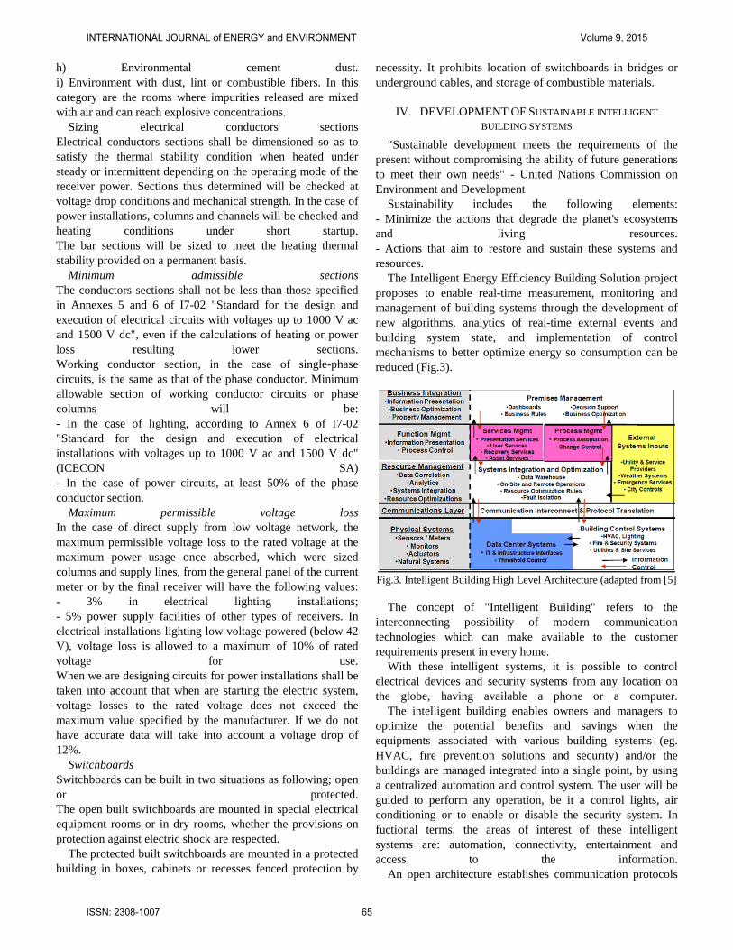
The Intelligent Energy Efficiency Building Solution project proposes to enable real-time measurement, monitoring and management of building systems through the development of new algorithms, analytics of real-time external events and building system state, and implementation of control mechanisms to better optimize energy so consumption can be reduced (Fig.3).
Fig.3. Intelligent Building High Level Architecture (adapted from [5]
The concept of "Intelligent Building" refers to the
interconnecting possibility of modern communication technologies which can make available to the customer requirements present in every home.
With these intelligent systems, it is possible to control electrical devices and security systems from any location on the globe, having available a phone or a computer. The intelligent building enables owners and managers to optimize the potential benefits and savings when the equipments associated with various building systems (eg. HVAC, fire prevention solutions and security) and/or the buildings are managed integrated into a single point, by using a centralized automation and control system. The user will be guided to perform any operation, be it a control lights, air conditioning or to enable or disable the security system. In fuctional terms, the areas of interest of these intelligent systems are: automation, connectivity, entertainment and access to the information. An open architecture establishes communication protocols
INTERNATIONAL JOURNAL of ENERGY and ENVIRONMENT Volume 9, 2015
ISSN: 2308-1007 65
that enable building control systems from different vendors to exchange information, to synchronize equipment and get optimal energy functioning of the building. Within intelligent buildings, intelligent management and control solutions include building management and energy convergence with security, life safety and fire safety, communication, IT equipments rooms, automation machines and specific applications to create a highly adaptable building , durable and economical. In conclusion, the energy-efficient design, really comes from the growing need to manage the whole building as an integrated system.
V. INTELLIGENT BUILDING AUTOMATION AS A PART OF HIGH LEVEL ARCHITECTURE
The buildings automation concept involves the development of devices that do not require the intervention of the human operator to realize the purposes for which they were created.
In general, when we are talking about automation, people come in head images with a robot hand which is carrying things on assembly line (eg. to fix a door to a car, inserts some integrated circuits on a printed circuit board, etc.).
In reality we are thinkig about the automation devices which know what actions to take in case of special events.
The simplest example is the ability to program the house turning on lights with dusk while we are out of town. There are already vacuums that "walk through the house with the help of sensors and clean the mess, following before running out the battery, to reach the dock to recharge.
In the future, the refrigerator will know what foods stores, when foods expire and how much should be purchased to complete the assortment preseted "stock" and why not, to order them.
The ovens will have memory database with cooking instructions and the user will scan a bar code that will be a recipe, following that the device to prepare itself one dish, based on instructions from memory.
The house windows will be made of liquid crystal so that it can be adjusted brightness inside without resorting to louvers, only by changing the crystal orientation.
Certainly there will be many inventions that will revolutionize the future house. All you have to do is use your imagination to view any combination of automatic functions.
Automation of intelligent buildings examples: 1. Automation installation of indoor and outdoor lighting
- Making lighting according to natural light levels - reduces sensor lights to save 50% electricity. - Automatic operation of lighting depending on the presence of people in a room. - With the presence detectors, you can run the lighting command hallways crossing or entering a certain room
- Outdoor lighting control according to movement and the natural lighting. - You can use direct central switch or remote control to turn on and off various lights regardless of their location in the
building / room. - You can save and activate any lighting scenario, and achieve changes whenever you need.
2. Automation of air-conditioning - Continuous monitoring of operating parameters of the heating system and ventilation depending on the outside weather conditions, season, time of day, the presence of people in the room, etc. - Heating chambers can be adapted to your own lifestyle. In the morning you can automatically heat, to a comfortable level, only bedroom, bathroom and kitchen. When you arrive home in the evening, you can start heating the living room. - Stop automatic heating when sensors register window opening windows.
3. Command and control interior and exterior blinds / shutters. - Automatic operation of blinds or shutters depending on the season, day and the natural light. If in the summer the outdoor lighting is particularly strong, the shutters are closing automatically to relieve the cooling system too burdensome.
In the winter, open blinds so to be able to benefit from solar heating.
4. Monitoring and alarm security - There is a series of motion or presence sensors, magnetic contacts for doors and windows, cameras, temperature sensors, smoke, gas, flood, along with optical and acoustic security against fire, gas leak, flooding and unauthorized entry into your house - In case of fire signaling, power supply is automatically turned off and turned on emergency lighting, whose status is constantly monitored.
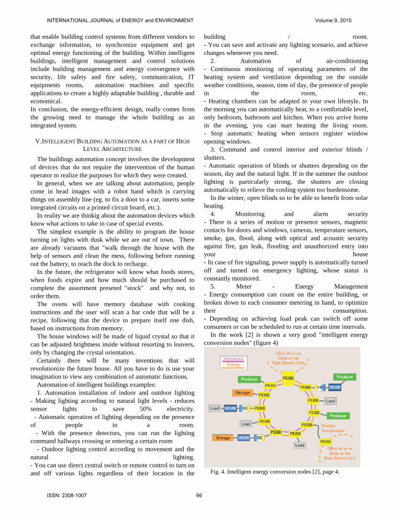
5. Meter - Energy Management - Energy consumption can count on the entire building, or broken down to each consumer metering in hand, to optimize their consumption. - Depending on achieving load peak can switch off some consumers or can be scheduled to run at certain time intervals.
In the work [2] is shown a very good "intelligent energy conversion nodes" (figure 4)
Fig. 4. Intelligent energy conversion nodes [2], page 4.
INTERNATIONAL JOURNAL of ENERGY and ENVIRONMENT Volume 9, 2015
ISSN: 2308-1007 66

A. Automated house benefits
A home equipped with the latest automated systems should simplify our lives and no way to complicate it. In most cases the purpose of improving technology is to protect people and ensure their comfort.
Therefore, the integration of intelligent equipment in a residential infrastructure just makes life simpler and saves us time and money, indirectly. An intelligent house is one that is equipped with multiple systems for managing electricity, house maintenance costs, their payment through electronic systems, monitoring various ways, etc. The automation makes our house a practical multifunctional complex and easy to use, integrating harmoniously and coherently entire house audio and video, communication, cooling systems, lighting, security, internet, etc. We feel good to think that a "brain" is keeping monitoring our house to a pleasant temperature, the TV automatically starts when we enter the living room, the stereo starts at a certain time, the irrigation of our plants in the garden is made only when founds that the soil moisture has reached a low value. All these elements are common in a "digital home". These goals can be achieved due to careful software developed by specialized companies.
These programs are made on the idea of connecting separate or sequential use of such equipments
Therefore they must be constantly adaptable, willing to support new and new requirements as they arise.
For this reason, does not exist the condition of a direct dependence of a particular hardware manufacturer
We need to not forget that we use in our house equipments and accessories produced by different companies, based on
diverse technologies. For this reason it is imperative that the installed software
and hardware to be able to assimilate these technologies and then control them without any difficulty.
The "House Brain" can control the relays ordered various types of sensors (temperature, motion, lighting, smoke, etc..) surveillance cameras, audio-video equipments, power or calorie counters and more.
The common element of all these features is that it can be connected to a computer and controlled by it.
Monitoring of such equipments requires besides turning on lights, opening doors, triggering certain more complex operations and the management of certain crisis situations in the system, without the intervention of the owner. A very good example of Remote Monitoring of Intelligent Buildings Parameters is presented in the work [3].
The flow diagram of data collection and processing without connecting to a server is shown in Fig. 5. The possible controlled functions of the intelligent buildings could be as following: communication, fire&safety, high speed internet, security, access, water, energy, light, elevator, IP/ digital TV, 24/7 Monitoring, IP Telephony, HVAC.
Fig.5. Flow diagram of data collection and processing, without connecting to a server
If we are connecting the intelligent building to a WebDAV server the system could trigge certain more complex operations and the management of certain crisis situations in the system, without the intervention of the owner Fig. 6. In the work [4] is shown a very good representation of a
classic house heating and ventilation systems distribution (figure 7)
INTERNATIONAL JOURNAL of ENERGY and ENVIRONMENT Volume 9, 2015
ISSN: 2308-1007 67
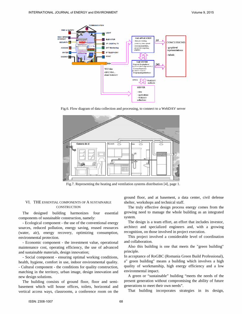
Fig.6. Flow diagram of data collection and processing, to connect to a WebDAV server
Fig.7. Representing the heating and ventilation systems distribution [4], page 1.
VI. THE ESSENTIAL COMPONENTS OF A SUSTAINABLE CONSTRUCTION
The designed building harmonizes four essential components of sustainable construction, namely:
- Ecological component - the use of the conventional energy sources, reduced pollution, energy saving, reused resources (water, air), energy recovery, optimizing consumption, environmental protection.
- Economic component - the investment value, operational maintenance cost, operating efficiency, the use of advanced and sustainable materials, design innovation;
- Social component - ensuring optimal working conditions, health, hygiene, comfort in use, indoor environmental quality. - Cultural component - the conditions for quality construction, matching in the territory, urban image, design innovation and new design solutions.
The building consists of ground floor, floor and semi-basement which will house offices, toilets, horizontal and vertical access ways, classrooms, a conference room on the
ground floor, and at basement, a data center, civil defense shelter, workshops and technical staff.
The truly effective design process energy comes from the growing need to manage the whole building as an integrated system.
The design is a team effort, an effort that includes investor, architect and specialized engineers and, with a growing recognition, on those involved in project execution.
This project involved a considerable level of coordination and collaboration.
Also this building is one that meets the "green building" principle. In acceptance of RoGBC (Romania Green Build Professional), a" green building" means a building which involves a high quality of workmanship, high energy efficiency and a low environmental impact.
A green or “sustainable” building “meets the needs of the present generation without compromising the ability of future generations to meet their own needs”.
That building incorporates strategies in its design,
INTERNATIONAL JOURNAL of ENERGY and ENVIRONMENT Volume 9, 2015
ISSN: 2308-1007 68
construction and operation in order to reduce energy use and minimize or eliminate negative impact on the planet [8].
VII. COMPUTER AIDED DESIGN (CAD) AND THE BUILDING ENVIRONMENT CONCEPT PROJECT
The building environment project is a "symbol marking the organization's transformation into a environmental responsible company"
Environmental building project homogeneity design stages depend heavily on their incorporation into a whole. The built environment is a particular manifestation of technological innovation and the modes by which we apply technology in the design, construction and use has direct implications on energy consumption. To achieve an efficient and quality product, Computer Aided Design (CAD) seems to be indispensable.
Working optimal method chosen for the first phase of building design is: 2D lines, 3D components work or a hybrid model construction. There are all standard interfaces for efficient data exchange with other programs (over 50 in number including DWG, DXF, DGN, IFC, PDF).
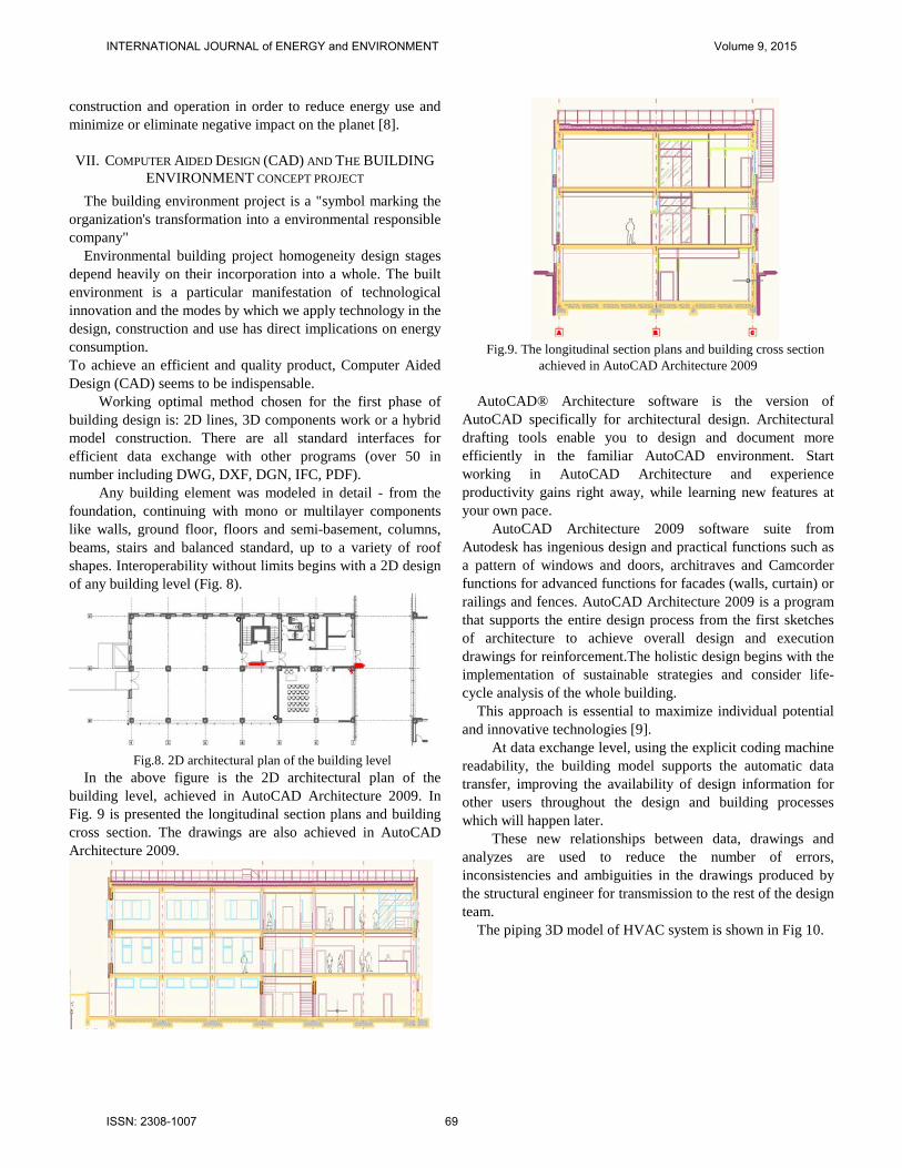
Any building element was modeled in detail - from the foundation, continuing with mono or multilayer components like walls, ground floor, floors and semi-basement, columns, beams, stairs and balanced standard, up to a variety of roof shapes. Interoperability without limits begins with a 2D design of any building level (Fig. 8).
Fig.8. 2D architectural plan of the building level
In the above figure is the 2D architectural plan of the building level, achieved in AutoCAD Architecture 2009. In Fig. 9 is presented the longitudinal section plans and building cross section. The drawings are also achieved in AutoCAD Architecture 2009.
Fig.9. The longitudinal section plans and building cross section
achieved in AutoCAD Architecture 2009 AutoCAD® Architecture software is the version of
AutoCAD specifically for architectural design. Architectural drafting tools enable you to design and document more efficiently in the familiar AutoCAD environment. Start working in AutoCAD Architecture and experience productivity gains right away, while learning new features at your own pace.
AutoCAD Architecture 2009 software suite from Autodesk has ingenious design and practical functions such as a pattern of windows and doors, architraves and Camcorder functions for advanced functions for facades (walls, curtain) or railings and fences. AutoCAD Architecture 2009 is a program that supports the entire design process from the first sketches of architecture to achieve overall design and execution drawings for reinforcement.The holistic design begins with the implementation of sustainable strategies and consider life-cycle analysis of the whole building.
This approach is essential to maximize individual potential and innovative technologies [9].
At data exchange level, using the explicit coding machine readability, the building model supports the automatic data transfer, improving the availability of design information for other users throughout the design and building processes which will happen later.
These new relationships between data, drawings and analyzes are used to reduce the number of errors, inconsistencies and ambiguities in the drawings produced by the structural engineer for transmission to the rest of the design team.
The piping 3D model of HVAC system is shown in Fig 10.
INTERNATIONAL JOURNAL of ENERGY and ENVIRONMENT Volume 9, 2015
ISSN: 2308-1007 69

Fig.10. The piping 3D model of HVAC system Also, all HVAC piping systems have been set up in
AutoCAD Architecture 2009. The structural model plays a central role in this process. The
effective coordination and review meetings occur when architectural; structural and installations models are available to be combined into a single virtual model. In Fig. 11 are represented the cable routing for IT equipment and electric cables in wireframe mode type (Fig. 11 a) and the cable routing for building level in shade mode type (Fig. 11 b).
Fig.11a.The cable routing for IT equipment and electric cables in
wireframe mode type
Fig.11b.The cable routing for building level in shade mode type
The cable routing was designed by CAD-2D dwg files of
architectural plans of building levels. For such buildings are important both facilities with all
categories installations and the architect ability to think enough
flexible space to allow its adaptation to any type of activity. In this project, using MATLAB programming environment,
was performed electrical power and lighting sizing and was calculated earthing resistance.
VIII. THE INTERACTIVE PROGRAM OF MATLAB MATLAB (MATrix LABoratory) is an interactive program
for processing numerical data provided in a vectorial or matrix form.
MATLAB includes specific applications called TOOLBOX sites. These are extensive collections of MATLAB functions that are developing the programming environment from one variant to another, in order to solve specific problems. In the case of signal processing we will work mostly with "Signal Processing Toolbox".
MATLAB works with programs contained in the files. Files which are containing MATLAB instructions are called M file (its have extension .m). M files can be regarded as macros of MATLAB commands saved in the files with the extension .m., ie namefile.m.
An m.file can either be a function of input and output variables or a list of commands.
A MATLAB program can be written as script files or as a function files. A script file is an external file that contains a sequence of MATLAB commands
After full implementation of a script file, the created variables by this type of files remain in the application memory. If the first line of the file contains the word "function", that file is a function file, which is characterized by the fact that it can work with arguments.
At the end of the execution of a function, in computer memory remains only its output variables.
MATLAB works with two types of windows: a command window and a graphics window. At a time we can open only a command window.
The graphics window is used in graphic representation of the data. Multiple graphics windows may be opened in the same time
For electric power sizing were used as general data entry as following: the number of receivers (n) correction factor (cn), power factor (cosfic) demand coefficient (kc) section in mm2 (s), the intensity depending on the conductor section (I), network voltage (Un), number of air vents (x, y), the installed capacity (Pid), output power (Putild), power consumption (Pc), the intensity of current consumption (Ic). Using formulas and comparisons we obtain as output the selected conductor cross section, in mm2. The floor electrical installation force consists of: air vents, central air handling units, power air conditioning, power rack, central fire detection, forced entry central, circuit sockets and backup circuits (Table 1).
Table 1 air vents x1=15; % number of air vents v1=7*50; %[W]
INTERNATIONAL JOURNAL of ENERGY and ENVIRONMENT Volume 9, 2015
ISSN: 2308-1007 70
v2=8*90; %[W] Pid=v1+v2; % installed capacity Putilvcv=1600; % output power cnvcv=interp1(n,cn,x1); % Correction coefficient; kcvcv=kc(2)+((1-kc(2))/cnvcv); % corrected demand
coefficient; Pcvcv=kcvcv*Piv; % power consumption; Icvcv=Putilvcv/(Un*cosfic(2)) % intensity of current
consumption if Icvcv < ICu(1)
svcv=s(1) % conductor cross section [mm2]
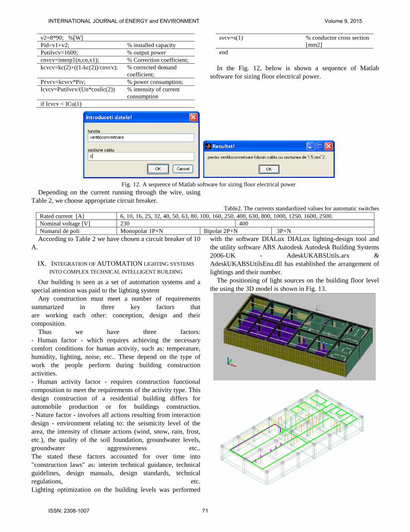
end In the Fig. 12, below is shown a sequence of Matlab
software for sizing floor electrical power.
Fig. 12. A sequence of Matlab software for sizing floor electrical power
Depending on the current running through the wire, using Table 2, we choose appropriate circuit breaker.
Table2. The currents standardized values for automatic switches Rated current [A] 6, 10, 16, 25, 32, 40, 50, 63, 80, 100, 160, 250, 400, 630, 800, 1000, 1250, 1600, 2500. Nominal voltage [V] 230 400 Numarul de poli Monopolar 1P+N Bipolar 2P+N 3P+N
According to Table 2 we have chosen a circuit breaker of 10 A.
IX. INTEGRATION OF AUTOMATION LIGHTING SYSTEMS INTO COMPLEX TECHNICAL INTELLIGENT BUILDING
Our building is seen as a set of automation systems and a special attention was paid to the lighting system
Any construction must meet a number of requirements summarized in three key factors that are working each other: conception, design and their composition.
Thus we have three factors: - Human factor - which requires achieving the necessary comfort conditions for human activity, such as: temperature, humidity, lighting, noise, etc.. These depend on the type of work the people perform during building construction activities. - Human activity factor - requires construction functional composition to meet the requirements of the activity type. This design construction of a residential building differs for automobile production or for buildings constructios. - Nature factor - involves all actions resulting from interaction design - environment relating to: the seismicity level of the area, the intensity of climate actions (wind, snow, rain, frost, etc.), the quality of the soil foundation, groundwater levels, groundwater aggressiveness etc.. The stated these factors accounted for over time into "construction laws" as: interim technical guidance, technical guidelines, design manuals, design standards, technical regulations, etc. Lighting optimization on the building levels was performed
with the software DIALux DIALux lighting-design tool and the utility software ABS Autodesk Autodesk Building Systems 2006-UK - AdeskUKABSUtils.arx & AdeskUKABSUtilsEnu.dll has established the arrangement of lightings and their number.
The positioning of light sources on the building floor level the using the 3D model is shown in Fig. 13.
INTERNATIONAL JOURNAL of ENERGY and ENVIRONMENT Volume 9, 2015
ISSN: 2308-1007 71

Fig.13. Positioning of light sources on the building floor level the using the 3D model
The positioning of light sources on the building floor level the using the 2D model is shown in Fig. 13.
Fig.13. Positioning of light sources on the building floor level the
using the 2D model
In order to create a energy efficient building, we need to imply intelligent design, right from the beginning of the project.
X. CONCLUSION The global approach in terms of the intelligent design of
buildings concept is clearly subordinated to economic criteria expressed more or less in a rigorous form of terms such as: increasing labor productivity of those who are working in such buildings, administrative improvement, cost reduction on information technology and communications, insurance of develped activities, obtaining increased intercooperation facilities, improving ergonomic requirements and other requirements relative to human activities (culture, entertainment, sports)
Within the intelligent buildings, the intelligent management and control solutions include convergence of building management and energy with security, life safety and fire safety, communication, IT equipment rooms for IT equipments, machines automation and vertical-specific applications to create a highly adaptable, durable and economical building.
Graphics are engineers creative works and are, traditionally, results of translated based on CAD drawings. Currently, the collaborative design makes a more sophisticated sense, when referring to the design of the built environment. Organizations can improve their efficiency and productivity through collaboration contacts and collective intelligence networking and continuous virtual communication between team members.
REFERENCES [1] Popa. L.,S.S.Duicu, Collaborative and Integrated Designing of
Intelligent Sustainable Buildings, ADVANCES in INFORMATION SCIENCE and APPLICATIONS -VOLUMES I& II, Proceedings of the 18th International Conference on Computers (part of CSCC '14), Proceedings of the 18th International Conference on Computers(part of CSCC '14)Santorini Island, Greece July 17-21, 2014, pp 497-504.
[2] Prof. dr. Mohamed Zahran, Smart Grid Technology, Vision, Management and Control, WSEAS TRANSACTIONS on SYSTEMS, Issue 1, Volume 12, January 2013,pp.11-21
[3] Muresan, N. Orza, B. Vlaicu A. ,Remote Monitoring of Intelligent Buildings Parameters, International Conference; 6th, Energy, environment, ecosystems & sustainable development; Selected topics in energy, environment, sustainable development and landscaping; EEESD '10, 3rd WSEAS International conference on landscape architecture LA '10; 301-310
[4] Mircea Grigoriu, Marius Constantin Popescu, Intelligent Buildings Energy Supply Following Climate Parameters Variation Fuzzy Control, RECENT ADVANCES in COMPUTATIONAL INTELLIGENCE, Proceedings of the 4th WSEAS International Conference on COMPUTATIONAL INTELLIGENCE (CI '10) , Universitatea Politehnica, Bucharest, Romania, April 20-22, 2010,pp 143-147
[5] Dr. Jane L. Snowdon J. Jones. (2009, June 10). IBM Smarter Energy Management Systems for Intelligent Buildings. Available:
http://citris-uc.org/files/Snowden%20IBM%20Research%20061009.pdf [6] Elena Rastei, Romania Green Building Council (2012, March 7).Cladiri
Verzi: Proiectare Sustenabila. Design Integrat. Available:http://www.ecomagazin.ro/cladiri-verzi-proiectare-sustenabila-design-integrat/
[7] Cristian CIUREA, “A Metrics Approach for Collaborative Systems,” Informatica Economică, vol. 13, no. 2, pp. 41–49, Feb. 2009.
[8] Paul Rinder, RoGBC Green buildings.Principles, assessment and certification, design. Available:http://www.euroconferinte.ro/prezentari/Tema107.pdf
[9] http://www.autodesk.com/products/autodesk-autocad-architecture/overview.
INTERNATIONAL JOURNAL of ENERGY and ENVIRONMENT Volume 9, 2015
ISSN: 2308-1007 72