an interactive design system for pop-up cards with a ...iizuka/projects/popup/data/fulltext.pdfsuch...
TRANSCRIPT
Vis Comput (2011) 27: 605–612DOI 10.1007/s00371-011-0564-0
O R I G I NA L A RT I C L E
An interactive design system for pop-up cards with a physicalsimulation
Satoshi Iizuka · Yuki Endo · Jun Mitani ·Yoshihiro Kanamori · Yukio Fukui
Published online: 20 April 2011© Springer-Verlag 2011
Abstract We present an interactive system that allows usersto design original pop-up cards. A pop-up card is an interest-ing form of papercraft consisting of folded paper that formsa three-dimensional structure when opened. However, it isvery difficult for the average person to design pop-up cardsfrom scratch because it is necessary to understand the mech-anism and determine the positions of objects so that pop-upparts do not collide with each other or protrude from thecard. In the proposed system, the user interactively sets andedits primitives that are predefined in the system. The sys-tem simulates folding and opening of the pop-up card usinga mass–spring model that can simply simulate the physicalmovement of the card. This simulation detects collisions andprotrusions and illustrates the movement of the pop-up card.The results of the present study reveal that the user can de-sign a wide range of pop-up cards using the proposed sys-tem.
S. Iizuka (�) · Y. Endo · J. Mitani · Y. Kanamori · Y. FukuiDepartment of Computer Science, University of Tsukuba, 1-1-1Tenno-dai, Tsukuba, Ibaraki 305-8573, Japane-mail: [email protected]
Y. Endoe-mail: [email protected]
J. Mitanie-mail: [email protected]
Y. Kanamorie-mail: [email protected]
Y. Fukuie-mail: [email protected]
J. MitaniJST ERATO, 1-28-1 Koishigawa, Bunkyo-ku, Tokyo 112-0002,Japan
Keywords Pop-up card · Interactive design system ·Mass–spring model
1 Introduction
The pop-up card is an interesting form of papercraft inwhich a three-dimensional structure appears when the cardis opened, and the structure is folded flat when the card isclosed. Pop-up cards are roughly classified into two types:90-degree and 180-degree cards. The 90-degree card is con-structed by adding cuts and folds to a single piece of paperso that a structure pops up when the card is opened 90 de-grees. Such cards are sometimes referred to as origami ar-chitectures. The 180-degree card is constructed from multi-ple pieces of paper, and a structure pops up when the card isopened 180 degrees.
Several geometric constraints must be satisfied when apop-up card is designed so that the three-dimensional struc-ture pops up and can be folded flat without tearing or crush-ing. Knowledge of the constraints and mechanisms is re-quired, and designing a pop-up card is difficult for the av-erage person. The pop-up mechanisms of the 180-degreecard are usually more difficult to understand intuitively, ascompared with the 90-degree card, because the 180-degreecard is assembled from multiple pieces. Some 180-degreecards designed by artists have very complicated structures.A practical approach to the design of a 180-degree card is tocombine several prepared primitives, which are guaranteedto flatten when arranged appropriately. Using this approach,we can incrementally construct complicated shapes. How-ever, problems such as collisions between parts or the pro-trusion of part of the structure often occur after the cards areassembled. Therefore, pop-up cards are usually designed byprofessionals who have knowledge and experience.

606 S. Iizuka et al.
Fig. 1 An example of a 180-degrees type pop-up card designed withour system
In the present paper, we propose a design system thatenables novice users to design original pop-up cards in-teractively using intuitive operations. The target card is a180-degree card that is composed of several predefinedprimitives such as cylinders, cubes, and cones. Figure 1shows an example target. In the proposed system, the usersplace primitives on a card and edit the scales, alignments,and leaning angles of these primitives using a simple inter-face. The alignments are adjusted automatically using thesystem based on its geometric constraints. With the help ofthe proposed system, the users can concentrate on editingwithout having to worry about the constraints. The detailedappearance of the primitives can be changed by mappingtransparent texture images. The users can make actual pop-up cards by printing out templates of the parts generated bythe system. Furthermore, the proposed system simulates theclosing and opening motions of the pop-up card. The userscan determine whether there are collisions between partsduring closing and opening. Our system can also determinewhether all of the parts fit into the card when the card isclosed. This simulation helps the users avoid the trial-and-error process in making pop-up cards using actual materials.
The flow of designing a pop-up card using the proposedsystem is as follows:
1. Select a primitive from a pre-defined primitives list.2. Specify the location at which the primitive is to be
placed. The positions of fixed points are automaticallyadjusted such that they will be able to pop-up and befolded correctly.
3. Edit the positions, scales, and leaning angles of the prim-itive through mouse operations. The system guaranteesthat geometric constraints are satisfied even after theseoperations.
4. Confirm the simulated motion of closing and opening thecard. When collisions between primitives or a protrud-ing part of primitives are detected, the system displays awarning massage.
5. Iterate steps 1 through 4 in an arbitrary order until a de-sired pop-up card is obtained.
6. Print out and assemble the templates.
Okamura and Igarashi [10] proposed an interactive sys-tem for designing a 180-degree of pop-up card. The appear-ance of the proposed system is similar to the system theyproposed. The difference lies in the method of simulating theclosing and opening of the card. Their system analyticallycalculates the position of each vertex on primitives duringthe simulation. Since expressing the movements of all ver-tices in a primitive in analytical form is not straightforward,it is difficult to implement a wide variety of primitives ona system. Their system involves five types of primitives. Onthe other hand, the system proposed herein involves physicalsimulation based on a simple mass–spring model. The ad-vantage of the proposed approach is the ease of adding dif-ferent types of primitives to the system because movementsof these primitives are simulated based on a common phys-ical model. Moreover, primitives that have curved surfaces,such as cylinders, that are difficult to simulate analyticallycan be treated in the same framework. We implemented 14types of primitives in the proposed system. Combining thesemultiple primitives, the user can design a greater variety ofpop-up cards than is possible with existing systems.
The remainder of the present paper is organized as fol-lows. Section 2 describes research related to the design of apop-up card using a computer. Section 3 describes in detailthe design of the structure of a pop-up card using the pro-posed system. Section 4 describes the physical simulationperformed in order to compute the motion of a pop-up cardduring closing and opening. Section 5 shows examples ofpop-up cards designed using the proposed system. Finally,conclusions are presented in Sect. 6.
2 Related work
Designing original pop-up cards by hand while consideringthe geometric constraints of the card is difficult for the av-erage person. Several approaches to aid in the design of apop-up card using a computer have been proposed.
2.1 90-degree card
Mitani and Suzuki [9] proposed a system for designing a90-degree pop-up card in which a user can add vertical orhorizontal polygons interactively. Hendrix and Eisenberg [5]proposed a system in which the user can design the flattenedpattern of a pop-up card by adding prepared primitive pat-terns. In contrast to these interactive approaches, Li et al. [7]proposed a fully automated system for generating a pop-up card from an existing three-dimensional polygonal meshmodel.
These methods, however, cannot be adopted for the de-sign of a 180-degree card because they are based on the
An interactive design system for pop-up cards with a physical simulation 607
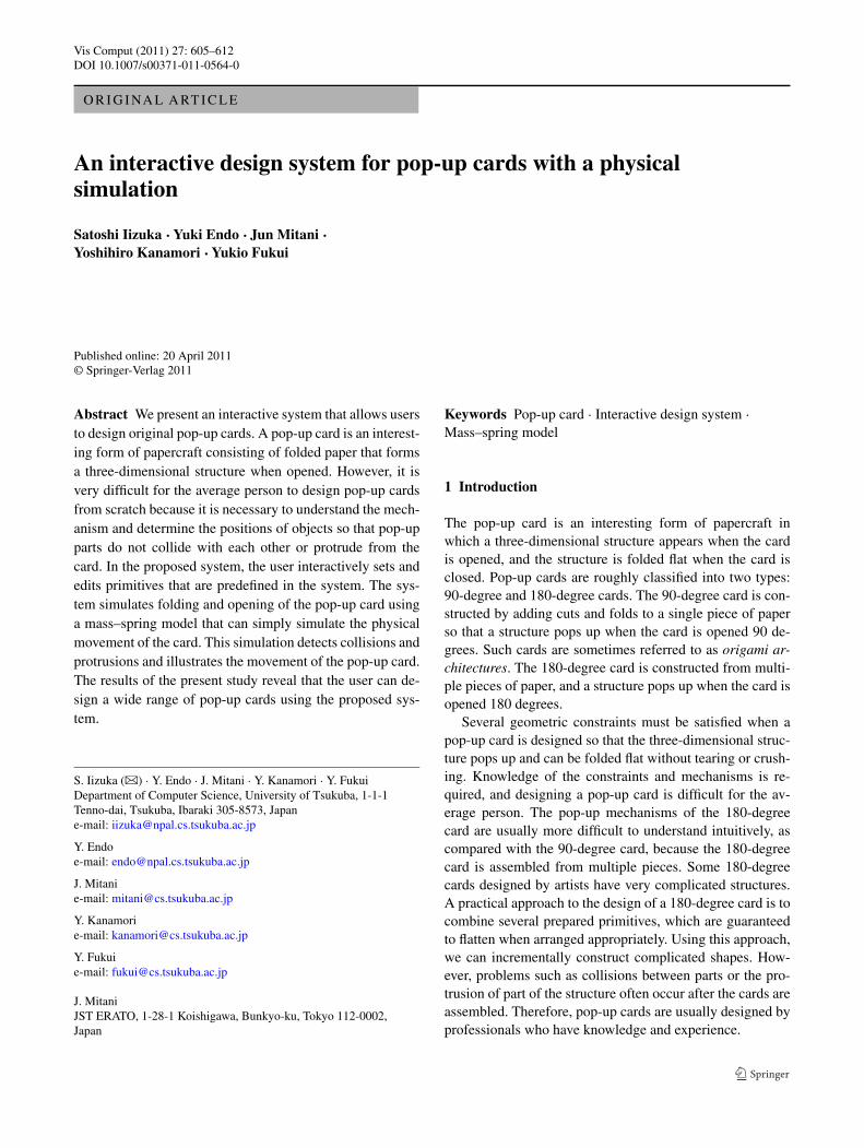
Fig. 2 V-fold (left) and single-slit (right)
geometric constraints of a 90-degree card, which is madeusing a single sheet. Therefore, we must consider differentmethods for designing a 180-degree card, which is assem-bled from several pieces.
2.2 180-degree card
Mitani and Suzuki [8] proposed a system for generating a180-degree pop-up card from an existing three-dimensionalpolygonal mesh by composing its cross-sections in latticeform. However, this system cannot create the target pop-up cards shown in Fig. 1 because the construction is setonly on the center fold line of the card. Lee et al. [6]described geometric constraints required for adding v-foldstructures to a card. However, they did not implement a de-sign system. Glassner [3, 4] described the motion of threebasic primitives (v-fold and symmetric/asymmetric single-slit (Fig. 2)), and introduced analytic solutions for calculat-ing the positions of vertices of primitives when the card isclosed and opened. Based on this description, Okamura andIgarashi [10] implemented a system with an interactive userinterface for designing a pop-up card, and they reported theresults of a user study. Five primitives, based on v-fold andshingle-slit primitives, are prepared in their system. The userselects a primitive and places it on the card. The user thenedits the shape under the constraints of the pop-up card. Weimplemented a user interface in the system proposed hereinby referring to their system.
3 Designing pop-up cards
In this section, we describe how to design the structure of apop-up card using the proposed system. A user first selects aprimitive from 14 predefined types. The user then places theprimitive on the empty card which consists of two rectanglesconnected by an edge along which the card is folded. Theuser then edits the shape of the primitive. A complicatedstructure is designed by adding primitives incrementally. Inthe following sections, these steps are described in detail.
3.1 Predefined primitives and edge types
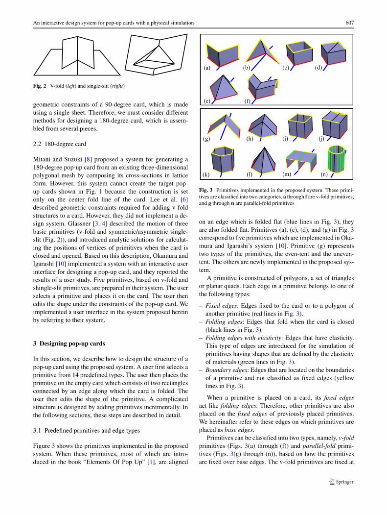
Figure 3 shows the primitives implemented in the proposedsystem. When these primitives, most of which are intro-duced in the book “Elements Of Pop Up” [1], are aligned
Fig. 3 Primitives implemented in the proposed system. These primi-tives are classified into two categories. a through f are v-fold primitives,and g through n are parallel-fold primitives
on an edge which is folded flat (blue lines in Fig. 3), theyare also folded flat. Primitives (a), (c), (d), and (g) in Fig. 3correspond to five primitives which are implemented in Oka-mura and Igarashi’s system [10]. Primitive (g) representstwo types of the primitives, the even-tent and the uneven-tent. The others are newly implemented in the proposed sys-tem.
A primitive is constructed of polygons, a set of trianglesor planar quads. Each edge in a primitive belongs to one ofthe following types:
– Fixed edges: Edges fixed to the card or to a polygon ofanother primitive (red lines in Fig. 3).
– Folding edges: Edges that fold when the card is closed(black lines in Fig. 3).
– Folding edges with elasticity: Edges that have elasticity.This type of edges are introduced for the simulation ofprimitives having shapes that are defined by the elasticityof materials (green lines in Fig. 3).
– Boundary edges: Edges that are located on the boundariesof a primitive and not classified as fixed edges (yellowlines in Fig. 3).
When a primitive is placed on a card, its fixed edgesact like folding edges. Therefore, other primitives are alsoplaced on the fixed edges of previously placed primitives.We hereinafter refer to these edges on which primitives areplaced as base edges.
Primitives can be classified into two types, namely, v-foldprimitives (Figs. 3(a) through (f)) and parallel-fold primi-tives (Figs. 3(g) through (n)), based on how the primitivesare fixed over base edges. The v-fold primitives are fixed at

608 S. Iizuka et al.
Fig. 4 Primitives are placed on base edges (shown in red lines)
Fig. 5 A user can edit the shapes of primitives by changing the width,height, depth, and leaning angle while satisfying the constraints. Theseexamples are obtained from primitive (f) in Fig. 3
two edges to polygons of the card or other primitives. Thesetwo edges are not parallel to the base edge. The parallel-foldprimitives have two or more fixed parallel edges.
3.2 Placing and editing primitives
In order to place a primitive on a card, the user selects a baseedge and then specifies a position on the edge. Since, at thebeginning, there is only a single base edge, which connectsthe two rectangles of the card, the first primitive is placedonto this base edge, after which the card acquires severalbase edges. The user constructs a complicated structure byrepeatedly selecting primitives and placing these primitiveson base edges, as shown in Fig. 4.
The user can edit the shape of a primitive after placementby changing the width, height, depth, and leaning angle bydragging a mouse. Not to violate the geometric constraints,angles between the base edge and the fixed edges on theprimitive are kept constant. The user interface implementedin the proposed system is basically the same as that intro-duced by Okamura and Igarashi [10]. Figure 5 shows someedited examples of primitive (f) in Fig. 3.
In addition, the user can place a transparent texture imageon a polygon of a primitive in order to change the appear-ance of the polygon, as shown in Fig. 6.
4 Physical simulation of opening and closing
An important factor of the pop-up card is the motion thatoccurs as the three-dimensional structure appears from the
Fig. 6 The appearance of a primitive is changed by applying a trans-parent texture image. a The texture image. Transparent parts are col-ored black. b The shape of a primitive. c The appearance of the primi-tive when the texture is applied to each polygon
Fig. 7 Mass–spring model. a A triangle and a rectangle are repre-sented by a network of springs. b A hinge-spring is added to an edgefor which the angle must be maintained constant
closed flat card. Simulating the motion of the structure isneeded in order to confirm the effect of the pop-up cards.Furthermore, the user can check for the existence of errors inthe structure by means of the simulation before constructingan actual pop-up card. We performed a physical simulationbased on the mass–spring model.
4.1 Computing the coordinates of vertices using themass–spring model
We follow an approach proposed by Furuta et al. [2] inwhich the motion of a piece of folded paper is simulated us-ing a mass–spring model. They used this model to simulateorigami. In the present study, we use this model to simulatepop-up cards.
The shape of a primitive is represented by a network ofsprings. For example, three springs are placed on the edgesof a triangle, and six springs are placed on edges and diago-nals of a quadrangle, as shown in Fig. 7(a).
While the vertices of the fixed edges are fixed to the cardor other primitives, other vertices move so as to maintain thelengths of the springs at their rest lengths during a simula-tion. As a result, the whole structure pops-up when the cardopens. When the card closes, the structure flattens.
The force Fi acting on a vertex i, the velocity vi , and thecoordinate ri of the vertex i are defined as follows:
Fi =∑
j
{k(|rij | − Lij
)rij − Dvij
}, (1)
vi (t + �t) = vi (t) + Fi (t)
m�t, (2)
ri (t + �t) = ri (t) + vi (t)�t, (3)

An interactive design system for pop-up cards with a physical simulation 609
where t is the simulation time, �t is the time step, k is thespring constant, Lij is the rest length of the spring betweenvertices i and j , rij is the relative coordinate of vertex i tovertex j , vij is the relative velocity of vertex i to vertex j ,D is the damper constant, and m is the mass of a vertex.In the present implementation, we set k = 8, D = 0.02, andm = 100. We use the explicit Euler method to calculate theposition of each vertex.
Although this model works well for almost all of theprimitives, primitives (m) and (n) in Fig. 3 which pop-updue to the elasticity of paper do not move as expected. Fig-ure 8 shows an example of the problem with primitive (m).The reason for this is that the simulation converges whenthe lengths of all of springs reach the rest lengths. In orderto solve this problem, we employ hinge-springs which sim-ulate the elasticity of paper. The hinge-springs are applied toedges for which the angle must be maintained.
A pair of forces H1 and H2 generated by a hinge-springact on vertices on polygons P1 and P2 which are connectedto the hinge-spring as shown in Fig. 7(b). The forces aredescribed as follows:
H1 = kh(φ0 − φ)n1, (4)
H2 = kh(φ0 − φ)n2, (5)
where φ0 and φ denote the rest angle and the current anglebetween P1 and P2, respectively. The spring constant of thehinge-spring is denoted as kh, and n1 and n2 are the unitnormal vectors of P1 and P2, respectively. We set kh = 0.02.
Using the forces generated by the hinge-springs, all ofthe primitives listed in Fig. 3 move as expected. Figure 9shows examples of the motion of (m) and (n) in Fig. 3. The
Fig. 8 A primitive without hinge springs that does not pop-up appro-priately
Fig. 9 The motions of primitives (m) and (n) after hinge springs areadded
cylindrical primitive (n) is divided into 14 quads, and hinge-springs having rest angles of 180 degrees are placed alongall of the vertical edges. Although this primitive is a roughapproximation of a cylinder, the primitive moves as a real-istic cylinder in the physical simulation of the present study.A typical example using this primitive is shown in the bot-tom of Fig. 10.
4.2 Error detection
The proposed system detects collisions between primitivesand protrusions during a simulation. Specifically, the systemdetermines whether the edges of a primitive penetrate thepolygons of other primitives and whether the coordinates ofall of the vertices are inside the card when the card is closed.The system displays a warning message when a problem isdetected. The user can then correct the problematic part be-fore constructing an actual pop-up card.
5 Results
We implemented the proposed system using C++ andOpenGL GLUT, and ran program on a PC with an IntelCore i7 620M (2.67 GHz, 4.00 GB RAM) and an NVIDIAQuadro NVS 3100M. We designed a number of pop-upcards using the proposed system and created actual cardsby assembling the printed patterns. The results are shownin Fig. 10. Designing a card required approximately 10 to20 minutes, excluding the time required to prepare textureimages. The top and the middle rows in Fig. 10 show ex-amples of a castle and a tortoise, respectively. The bottomrow in Fig. 10 shows an example of the Leaning Tower ofPisa constructed from a cylinder and two v-folds. The tem-plates of the parts are generated by the system. Flaps andalignment marks for gluing are automatically added to thetemplates of primitives according to their relative position.The correspondence between flaps and alignment marks aredistinguished by the colors.
Figure 11 shows an example of a complicated structuredesigned by an author. Four frames were captured duringa physical simulation. These pop-up cards contain primi-tives that are difficult to realize using existing analytical ap-proaches (primitives (m) and (n) in Fig. 3).
We conducted an informal user study involving two com-puter science students in order to examine how these sub-jects would design original pop-up cards. Neither of thesubjects had designed an original pop-up card prior to thisstudy. The subjects took a 10-minute lecture before startingto design their own pop-up cards using the proposed sys-tem. Figure 12 shows two of the pop-up cards designed inthis study. Designing Figs. 12(a) and (b) required approxi-mately 15 and 30 minutes, respectively. By making actual

610 S. Iizuka et al.
Fig. 10 Examples of pop-up cards designed using the proposed system. Top to bottom: a castle, a tortoise, and the Leaning Tower of Pisa. Left toright: screen shots of the proposed system, generated templates, and constructed cards
Fig. 11 Animation of a complicated pop-up card

An interactive design system for pop-up cards with a physical simulation 611
Fig. 12 Pop-up cards designed with two test users
pop-up cards, we confirmed that both of the pop-up cardswere flat when closed. After the study, we received posi-tive comments, such as “Viewing the motion of pop-up cardsthrough the simulation is fun.” and “The approach of puttingprimitives on a card is interesting.” On the other hand, wealso received the following comment: “I want to place aprimitive as a bridge between two separated primitives”. Atpresent, this operation is not available using the proposedsystem.
6 Conclusion and future research
We have presented an interactive system for designing pop-up cards. Using a physical simulation based on a mass–spring model, we were able to easily prepare several prim-itives using the proposed system. A number of primitives,including the shapes of which change due to the elastic-ity of paper, are appropriately simulated by applying hinge-springs. The proposed system enables the user to easily de-sign pop-up cards without special knowledge of pop-up carddesign.
On the other hand, there are limitations in the physicalsimulation implemented on our system. Although detailedappearances of primitives are modified by mapping trans-parent texture images as described in Sect. 3.2, this does notchange the structures of spring networks. If large holes areadded to a primitive by mapping an image, the holes will beignored in the simulation. Further, collisions between prim-itives do not affect the deformation of them. In the future,in order to take full advantage of the physical simulationagainst the analytical approach, we intend to improve col-lision detection and simulate the deformation of primitivesdue to collisions. We will also attempt to add more flexi-bility to the editing operations in order to enable the designof complicated mechanisms, like those that appear in cardsdesigned by artists.
Acknowledgements This work was supported by the Grant-in-Aidfor the Program for Enhancing Systematic Education in GraduateSchools, “Program for Development of ICT Solution Architects”, fromthe Ministry of Education, Culture, Sports, Science and Technology(MEXT) of Japan.
References
1. Elements of Pop Up: A Pop Up Book for Aspiring Paper Engi-neers
2. Furuta, Y., Kimoto, H., Mitani, J., Fukui, Y.: Computer model andmouse interface for interactive virtual origami operation. IPSJ J.48(12), 3658–3669 (2007) (in Japanese)
3. Glassner, A.: Interactive pop-up card design, part 1. IEEE Com-put. Graph. Appl. 22(1), 79–86 (2002)
4. Glassner, A.: Interactive pop-up card design, part 2. IEEE Com-put. Graph. Appl. 22(2), 74–85 (2002)
5. Hendrix, S.L., Eisenberg, M.A.: Computer-assisted pop-up designfor children: computationally enriched paper engineering. Adv.Technol. Learn. 3(2), 119–127 (2006)
6. Lee, Y.T., Tor, S.B., Soo, E.L.: Mathematical modelling and simu-lation of pop-up books. In: Proc. of Computers & Graphics 1996,vol. 20(1), pp. 21–31 (1996)
7. Li, X.Y., Shen, C.H., Huang, S.S., Ju, T., Hu, S.M.: Popop: au-tomatic paper architectures from 3D models. ACM Trans. Graph.29(4), 111 (2010)
8. Mitani, J., Suzuki, H.: Computer aided design for 180-degreeflat fold origamic architecture with lattice-type cross sections.J. Graph. Sci. Jpn. 37, 3 (2003) (in Japanese)
9. Mitani, J., Suzuki, H.: Computer aided design for origamic ar-chitecture models with polygonal representation. In: ComputerGraphics International 2004, Crete, Greece, 16–19 June, pp. 93–99 (2004)
10. Okamura, S., Igarashi, T.: An interface for assisting the designand production of pop-up card. In: Proc. of Smart Graphics 2009,pp. 68–78 (2009)
Satoshi Iizuka received his B.Sdegree in Computer Science fromthe University of Tsukuba in 2010,Japan. Since April 2010, he hasbeen a Master’s degree student inthe Department of Computer Sci-ence at University of Tsukuba. Hisresearch interests center on com-puter graphics and include interac-tive simulations, image-based mod-eling and image editing.
Yuki Endo received his B.S. degreein Computer Science from the Uni-versity of Tsukuba, Japan, in 2010.Since April 2010, he has been aMaster’s degree student in the De-partment of Computer Science atUniversity of Tsukuba. His researchinterests center on computer graph-ics and include interactive simula-tions and modeling of natural phe-nomena.

612 S. Iizuka et al.
Jun Mitani received his Ph.D. inEngineering from the Universityof Tokyo in 2004 for his researchon designing 3D papercraft modelswith a computer. In 2006, he startedworking at University of Tsukuba.His present post is an associate pro-fessor at the Graduate School ofSystems and Information Engineer-ing in University of Tsukuba. Heis studying about designing three-dimensional curved origami with acomputer as part of research activi-ties.
Yoshihiro Kanamori received hisB.S., M.S., and Ph.D. degrees inComputer Science from the Uni-versity of Tokyo, Japan, in 2003,2005, and 2009, respectively. SinceApril 2009, he has been an assis-tant professor in the Departmentof Computer Science at Universityof Tsukuba. His research interestscenter on computer graphics andinclude real-time rendering, point-based graphics, and interactive sim-ulations.
Yukio Fukui received his Ph.D. inEngineering from the University ofTokyo in 1993. He had been work-ing at the National Institute of Bio-science and Human-Technology,M.I.T.I. and the Institute of Infor-mation Sciences and Electronics atUniversity of Tsukuba since 1993and 1998, respectively. He has beena professor in the Department ofComputer Science at University ofTsukuba since 2004.