an introduction to architectural design: fire stations · pdhonline course a130 (2 pdh) an...
TRANSCRIPT
PDHonline Course A130 (2 PDH)
An Introduction to ArchitecturalDesign: Fire Stations
2012
Instructor: J. Paul Guyer, P.E., R.A., Fellow ASCE, Fellow AEI
PDH Online | PDH Center5272 Meadow Estates Drive
Fairfax, VA 22030-6658Phone & Fax: 703-988-0088
www.PDHonline.orgwww.PDHcenter.com
An Approved Continuing Education Provider

www.PDHcenter.com PDH Course A130 www.PDHonline.org
© J. Paul Guyer Page 2 of 35
An Introduction to Architectural Design: Fire Stations
J. Paul Guyer, P.E., R.A., Fellow ASCE, Fellow AEI
CONTENTS
1. INTRODUCTION 2. PLANNING AND LAYOUT 2.1 SITE DETERMINANTS 2.2 SPACE PROGRAM 2.3 LOCATION DETERMINANTS 2.4 COST 2.5 LAYOUT AND ADJACENCIES
This course is adapted from the Unified Facilities Criteria of the United States government, which is in the public domain, has unlimited distribution and is not copyrighted.

www.PDHcenter.com PDH Course A130 www.PDHonline.org
© J. Paul Guyer Page 3 of 35
1. INTRODUCTION
Architectural design is a largely subjective process that is best illustrated using a
“casebook” approach. In this course the “case” is fire stations.
This course provides guidance for development of fire stations appropriate for fighting
the two primary types of fires: Structure fires and Airport Crash fires. This information
may be used by architects, engineers, designers, and others involved in the
development and approval of fire station projects. It is intended to help all participants
better understand fire station requirements, programs, and design criteria so they can
effectively participate in the project development process. This course is not intended to
provide all of the information needed to identify project requirements or successfully
prepare project designs. Additional information on the unique program and design
requirements of projects must be obtained.

www.PDHcenter.com PDH Course A130 www.PDHonline.org
© J. Paul Guyer Page 4 of 35
2. PLANNING AND LAYOUT 2.1 SIZE DETERMINANTS.
Several factors determine the size of the facility.
2.1.1 General. Generally, the size of the station depends on the class of station, the
number of companies housed, the number and types of vehicles housed, and any
additional spaces required. The class of station will partially drive the number of spaces
required.
2.1.2 Needs Validation Assessment. Conduct a Needs Validation Assessment to
determine the class and required capacity in terms of personnel and vehicles of the new
or renovated station.
2.1.3 Types of Spaces. For a complete list of spaces, see Table 2-1. Fire Station
functional spaces fall into three main categories:
2.1.3.1 Maintenance and Apparatus. This includes the Apparatus Room which
houses the firefighting vehicles and the supporting maintenance spaces. The
maintenance spaces include both vehicle maintenance and storage and equipment
maintenance and storage (fire extinguishers, self-contained breathing apparatus
(SCBA), protective clothing, hoses, firefighting agents, etc.)
2.1.3.2 Administration and Training. This includes the appropriate offices, training
spaces, dispatch areas, administrative areas, etc.
2.1.3.3 Residential and Living. This includes the on-duty firefighters’ bedrooms,
toilets/showers, kitchen/dining, recreation, and “living room” areas.

www.PDHcenter.com PDH Course A130 www.PDHonline.org
© J. Paul Guyer Page 5 of 35
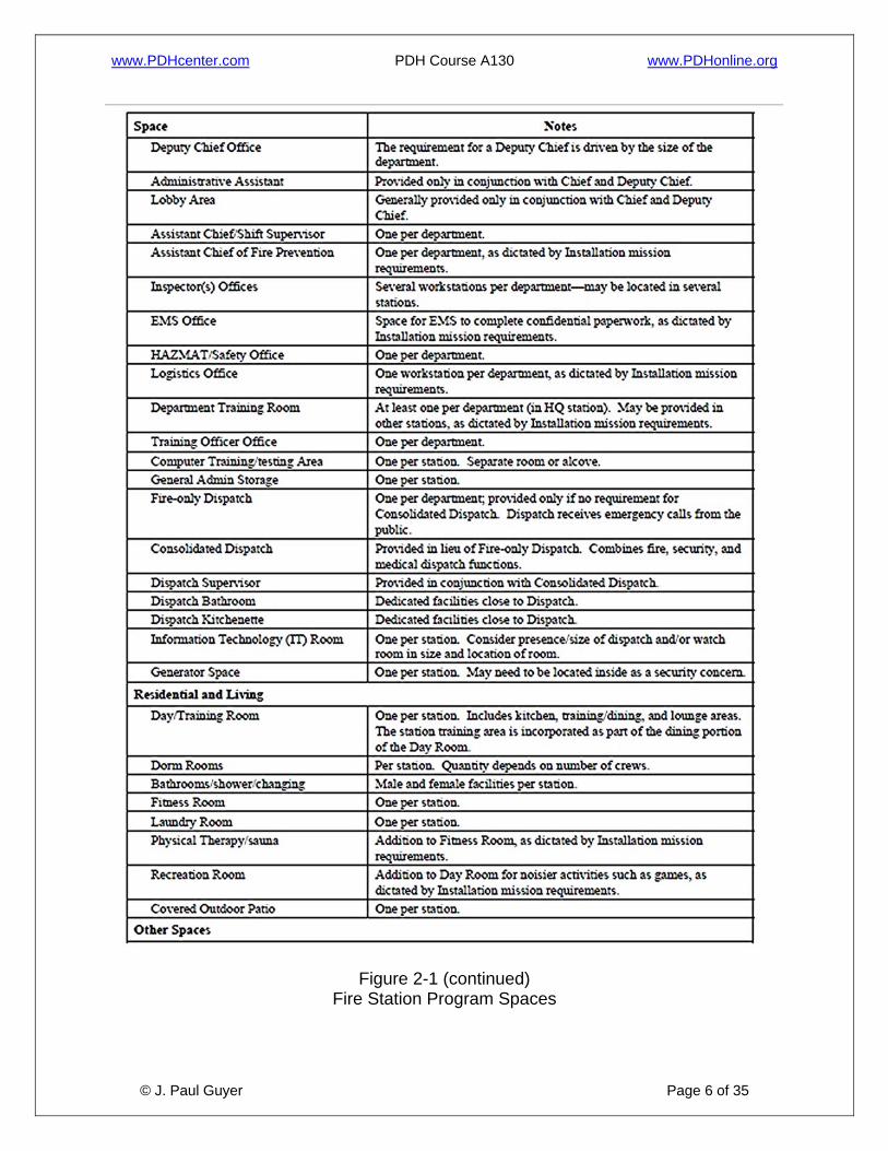
Table 2-1
Fire Station Program Spaces
www.PDHcenter.com PDH Course A130 www.PDHonline.org
© J. Paul Guyer Page 6 of 35
Figure 2-1 (continued) Fire Station Program Spaces

www.PDHcenter.com PDH Course A130 www.PDHonline.org
© J. Paul Guyer Page 7 of 35
2.2 SPACE PROGRAM. The space program for Fire Stations may be developed
through the use of an interactive worksheet. It is completed by first entering the
appropriate Service branch and then selecting the following: the type of station, the
class of station, the number of companies to be housed/dorm room count, the number
and class of vehicles to be housed, and the additional spaces required. As selections
are made, the program areas are calculated and summed for both the building and the
site. The worksheet must be filled out in collaboration with the appropriate fire
department representative(s). This interactive worksheet is available as a
downloadable Microsoft© Excel© file from the Whole Building Design Guide Web site
(http://dod.wbdg.org).
2.2.1 Critical Dimensions. To understand how the numbers in the interactive
worksheet are calculated, there are several critical dimensions that must be understood.
2.2.2.1 Apparatus Bays. The apparatus bays are sized based on the class of truck to be housed. See Table 2-2
for a list of common truck types. These types have been classified as follows in order to
standardize the size criteria:
• Large. These typically include structural aerial (ladder) trucks or large
tanker trucks with lengths greater than 11.58 m (38 ft.). The standardized
footprint (floor space occupied by the truck, not considering the space
around it) is 3.05 m by 15.24 m (10 ft. by 50 ft.).
• Medium. This class covers a wide range of vehicles from structural
pumper trucks and smaller tanker trucks to rescue and HAZMAT trucks.
• Small. These typically include ambulances, small rescue or HAZMAT trucks,
small brush units, and command vehicles. Small trucks have lengths less than
9.14 m (30 ft.). A separate vehicle bay size class is not designated for these
trucks. Depending on the actual size of the Small class truck, it may be housed in
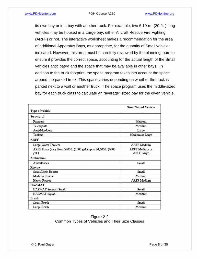
www.PDHcenter.com PDH Course A130 www.PDHonline.org
© J. Paul Guyer Page 8 of 35
its own bay or in a bay with another truck. For example, two 6.10-m- (20-ft.-) long
vehicles may be housed in a Large bay, either Aircraft Rescue Fire Fighting
(ARFF) or not. The interactive worksheet makes a recommendation for the area
of additional Apparatus Bays, as appropriate, for the quantity of Small vehicles
indicated. However, this area must be carefully reviewed by the planning team to
ensure it provides the correct space, accounting for the actual length of the Small
vehicles anticipated and the space that may be available in other bays. In
addition to the truck footprint, the space program takes into account the space
around the parked truck. This space varies depending on whether the truck is
parked next to a wall or another truck. The space program uses the middle-sized
bay for each truck class to calculate an “average” sized bay for the given vehicle.
Figure 2-2
Common Types of Vehicles and Their Size Classes

www.PDHcenter.com PDH Course A130 www.PDHonline.org
© J. Paul Guyer Page 9 of 35
2.2.2.2 Dorm Room Counts. The worksheet uses two methods to calculate the
number of dorm rooms needed (dorm room count). First, the user enters the number of
Structural companies and the number of ARFF companies, as appropriate. (If it is a
Structural station, ARFF companies are not permitted and vice versa.) The worksheet will calculate the number of dorm rooms using the number of companies entered. Second, the user adds or subtracts dorm rooms to accommodate ambulance companies, rescue companies, or cross-staffing of companies. The initial number of rooms plus or minus the modified number of rooms is the Final Dorm Room count. Dorm room counts must be coordinated with the Fire Chief. Cross staffed (x-staffed)
vehicles are staffed on an as needed basis by personnel assigned to another vehicle or
vehicles. X-staffed vehicles have no dedicated staff of their own.
Table 2-2
Sample Staffing by Vehicle Type

www.PDHcenter.com PDH Course A130 www.PDHonline.org
© J. Paul Guyer Page 10 of 35
2.2.3 Total Area. The space program developed through the use of the interactive
worksheet serves as a guideline for the Fire Station planning team and generally
represents the maximum space allowed. The final space program for a new Fire Station
will need to be carefully determined by Installation representatives and the appropriate
program office.
2.3 LOCATION DETERMINANTS. Several factors determine the most appropriate
and cost-effective location for a Fire Station.
2.3.1 Access/Response Time. The most critical determinant for the location of a Fire
Station is response time. In addition to response time, consider access to the station by
delivery vehicles, staff, and visitors. Consider that direct access and response time may
conflict with tightening antiterrorism (AT) criteria—ensure that trucks will not have to
cross access control points to reach a target structure or flightline. Facility site should
be prominent and easily visible from the target areas (structures or flightlines).
2.3.2 Size. Ensure adequate site space is available to accommodate the firefighting
vehicular turning radii, personnel parking, visitor parking, storage requirements, and
reserve vehicles (if applicable).
2.3.3 Sustainable Design. The location of a facility can have a significant impact on
achieving sustainable design rating points. Consider issues such as brownfield
redevelopment, access to public transportation, and reuse of existing paving and
hardscape when selecting a site.
2.4 COST. Facilities should be designed with the objective of achieving the lowest life
cycle cost over a 30-year period. To do so, the project’s design program must
adequately define the scope and performance requirements and match those needs
against a budget. Conversely, the budget must adequately support an appropriate and
high quality program and performance requirements.
www.PDHcenter.com PDH Course A130 www.PDHonline.org
© J. Paul Guyer Page 11 of 35
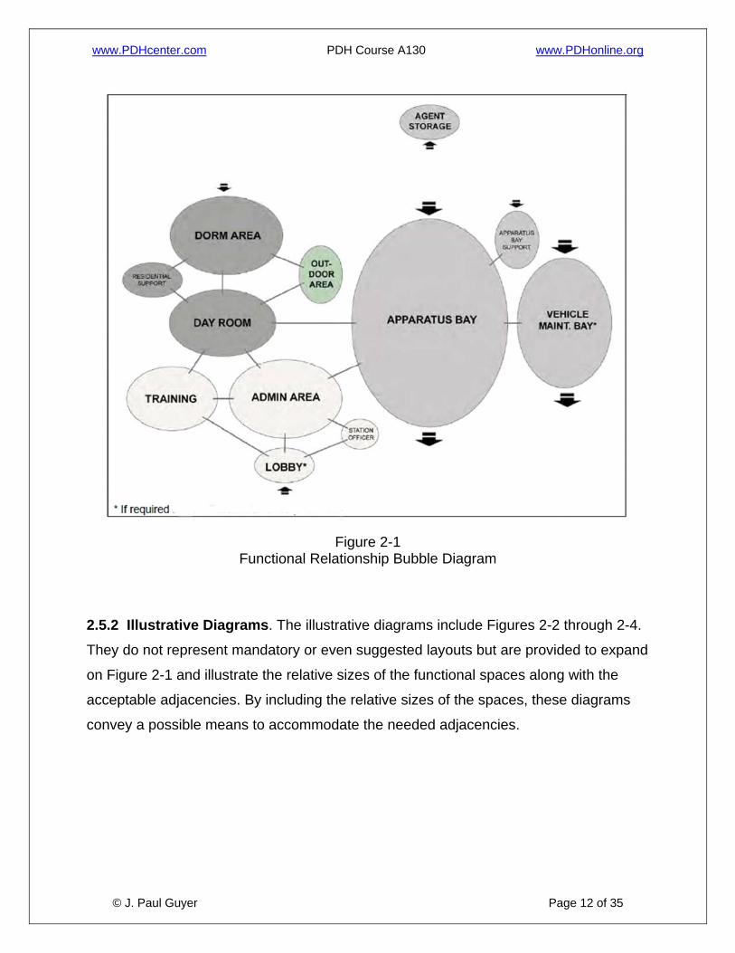
2.5 LAYOUT AND ADJACENCIES. As with the location determinants, the key internal
adjacencies are driven by response time. The location of the residential and living areas
must accommodate quick and clear access to the Apparatus Room for response in the
event of an alarm. The appropriate layout and adjacencies are illustrated through a
bubble diagram and a series of illustrative layout diagrams. In HQ/Main Stations and
Large HQ Stations, consider the relationship between the administrative areas and the
living areas. There may be a desire to separate these areas to provide a sense of
functional identity for each.
2.5.1 Functional Relationship Bubble Diagram. The bubble diagram in Figure 2-1
indicates the acceptable relative adjacencies of the functional spaces. Some of these
key adjacencies may be accommodated through a hallway rather than a direct
entrance/exit from one space to another. This is particularly true with the Apparatus
Room and the Day Room as many facility spaces need an adjacency with these two
spaces. Note that the “Apparatus Bay Support” area indicated in the diagrams includes
the following spaces, some of which may not be included in every station, depending
upon Installation mission requirements:
• SCBA Maintenance
• SCBA Compressor Room
• Work Room/Equipment Maintenance
• Equipment Wash/Disinfection
• Protective Clothing Laundry
• EMT Storage
• HAZMAT/CBRNE Equipment Storage
• Spare PPE Gear Storage
• Fire Extinguisher Inspection
• Fire Extinguisher Maintenance & Storage
• Flightline Fire Extinguisher Maintenance
www.PDHcenter.com PDH Course A130 www.PDHonline.org
© J. Paul Guyer Page 12 of 35
Figure 2-1
Functional Relationship Bubble Diagram
2.5.2 Illustrative Diagrams. The illustrative diagrams include Figures 2-2 through 2-4.
They do not represent mandatory or even suggested layouts but are provided to expand
on Figure 2-1 and illustrate the relative sizes of the functional spaces along with the
acceptable adjacencies. By including the relative sizes of the spaces, these diagrams
convey a possible means to accommodate the needed adjacencies.

www.PDHcenter.com PDH Course A130 www.PDHonline.org
© J. Paul Guyer Page 13 of 35
2.5.2.1 Figure 2-2.
This diagram illustrates a layout for a small, one- or two-company Satellite station.
Figure 2-2
Illustrative Layout Diagram A – Small Satellite
www.PDHcenter.com PDH Course A130 www.PDHonline.org
© J. Paul Guyer Page 14 of 35
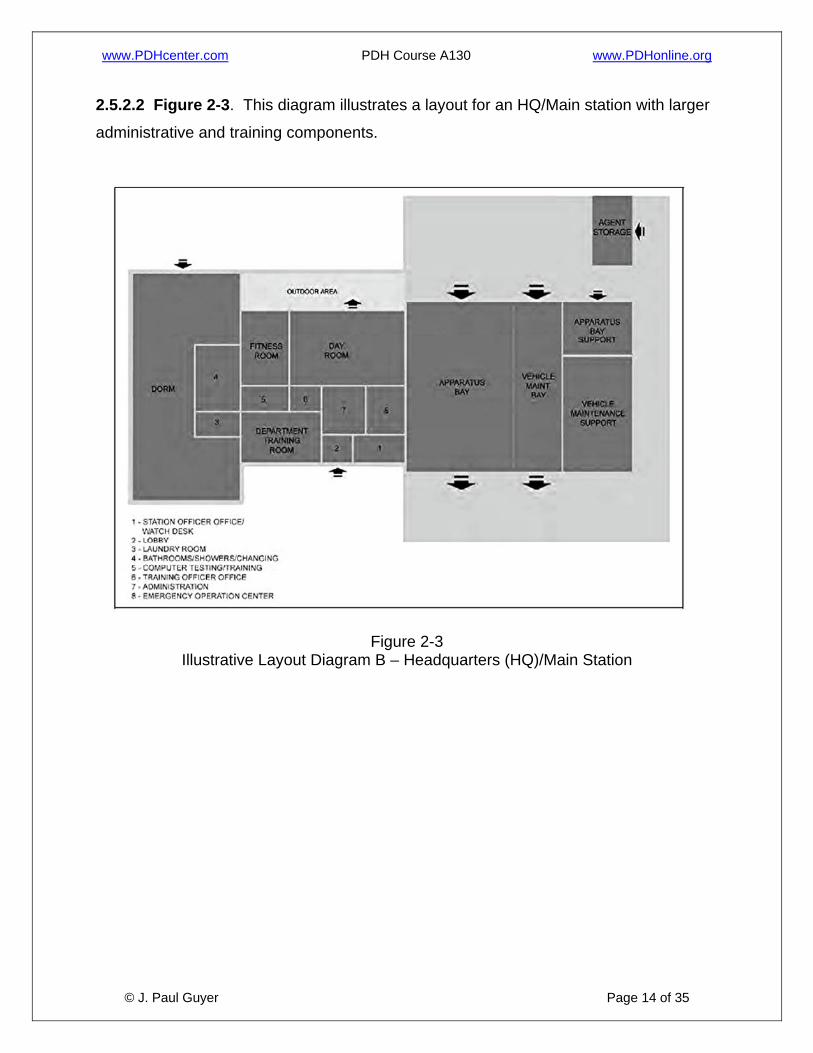
2.5.2.2 Figure 2-3. This diagram illustrates a layout for an HQ/Main station with larger
administrative and training components.
Figure 2-3
Illustrative Layout Diagram B – Headquarters (HQ)/Main Station

www.PDHcenter.com PDH Course A130 www.PDHonline.org
© J. Paul Guyer Page 15 of 35
2.5.2.3 Figure 2-4. This diagram illustrates a layout for a Large HQ station. This
diagram also captures some of the key relationships for any combination station,
regardless of size—in particular the need for separation of ARFF and Structural trucks
relative to a flightline.
Figure 2-4
Illustrative Layout Diagram C – Large HQ
2.5.3 Sample Floor Plans. Sample floor plans below further expand on these
illustrative diagrams. These do not represent mandatory or even suggested floor plans.
They are provided to illustrate possible means to accommodate the needed
adjacencies.

www.PDHcenter.com PDH Course A130 www.PDHonline.org
© J. Paul Guyer Page 16 of 35
Figure 2-5
Headquarters Station

www.PDHcenter.com PDH Course A130 www.PDHonline.org
© J. Paul Guyer Page 17 of 35
Figure 2-6
Large Headquarters Station

www.PDHcenter.com PDH Course A130 www.PDHonline.org
© J. Paul Guyer Page 18 of 35
Figure 2-7
Apparatus Bays – Large Vehicle Class
www.PDHcenter.com PDH Course A130 www.PDHonline.org
© J. Paul Guyer Page 19 of 35
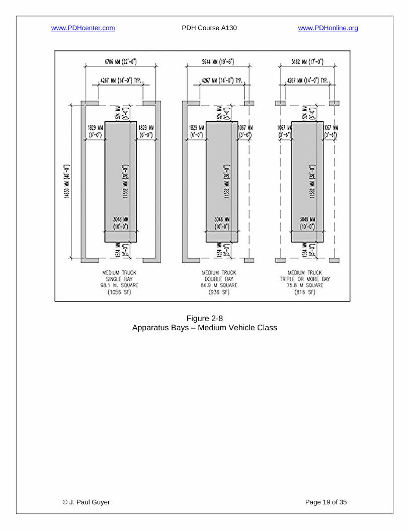
Figure 2-8
Apparatus Bays – Medium Vehicle Class

www.PDHcenter.com PDH Course A130 www.PDHonline.org
© J. Paul Guyer Page 20 of 35
Figure 2-9 Apparatus Bays – Large ARFF (Wide) Vehicle Class
www.PDHcenter.com PDH Course A130 www.PDHonline.org
© J. Paul Guyer Page 21 of 35
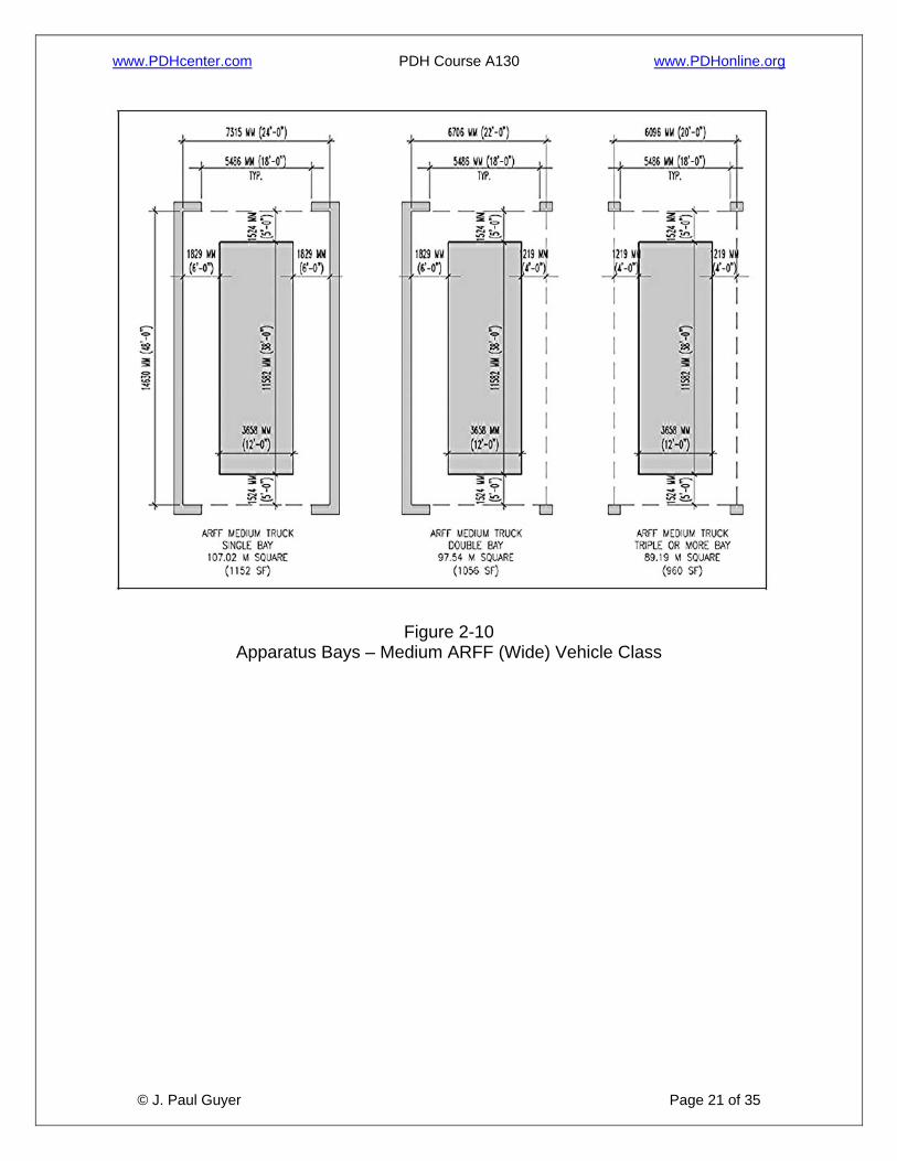
Figure 2-10 Apparatus Bays – Medium ARFF (Wide) Vehicle Class

www.PDHcenter.com PDH Course A130 www.PDHonline.org
© J. Paul Guyer Page 22 of 35
Figure 2-11 Department Training Room
www.PDHcenter.com PDH Course A130 www.PDHonline.org
© J. Paul Guyer Page 23 of 35
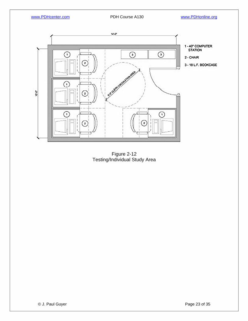
Figure 2-12 Testing/Individual Study Area
www.PDHcenter.com PDH Course A130 www.PDHonline.org
© J. Paul Guyer Page 24 of 35
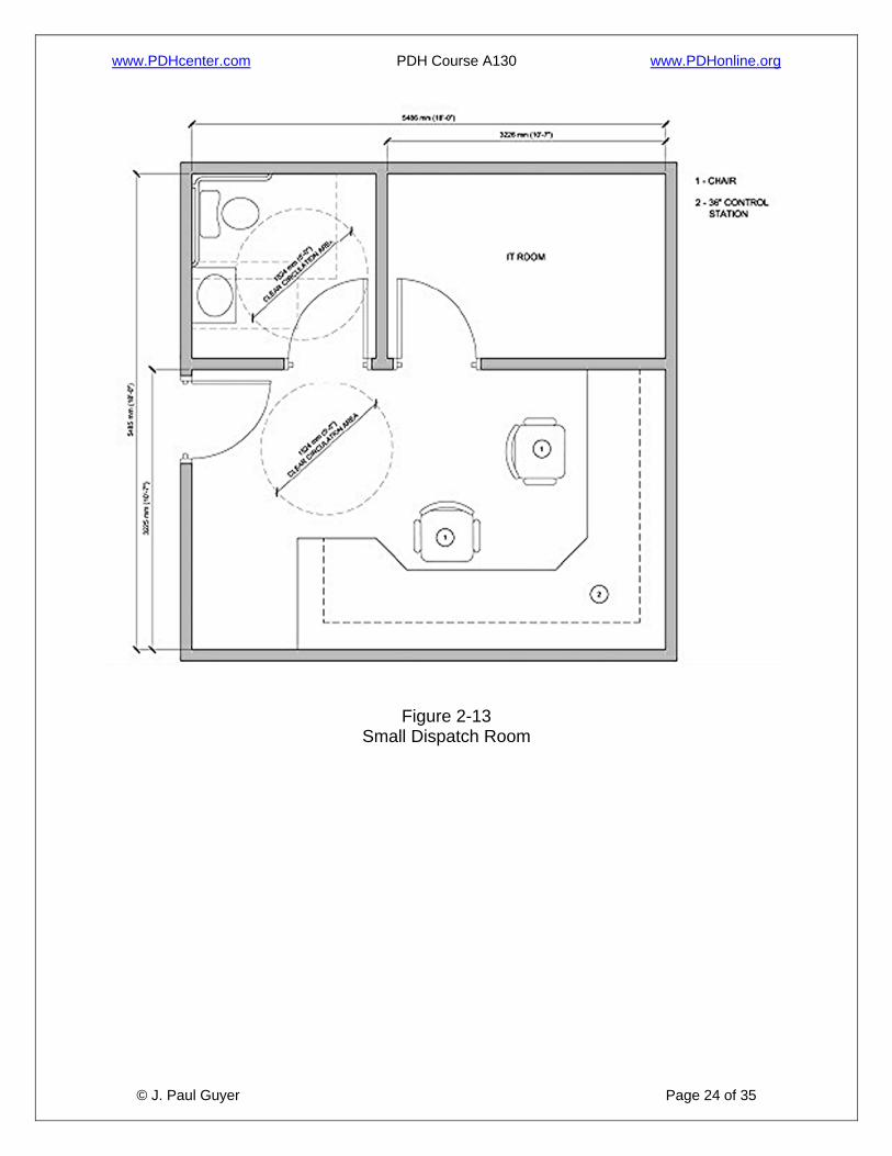
Figure 2-13 Small Dispatch Room
www.PDHcenter.com PDH Course A130 www.PDHonline.org
© J. Paul Guyer Page 25 of 35
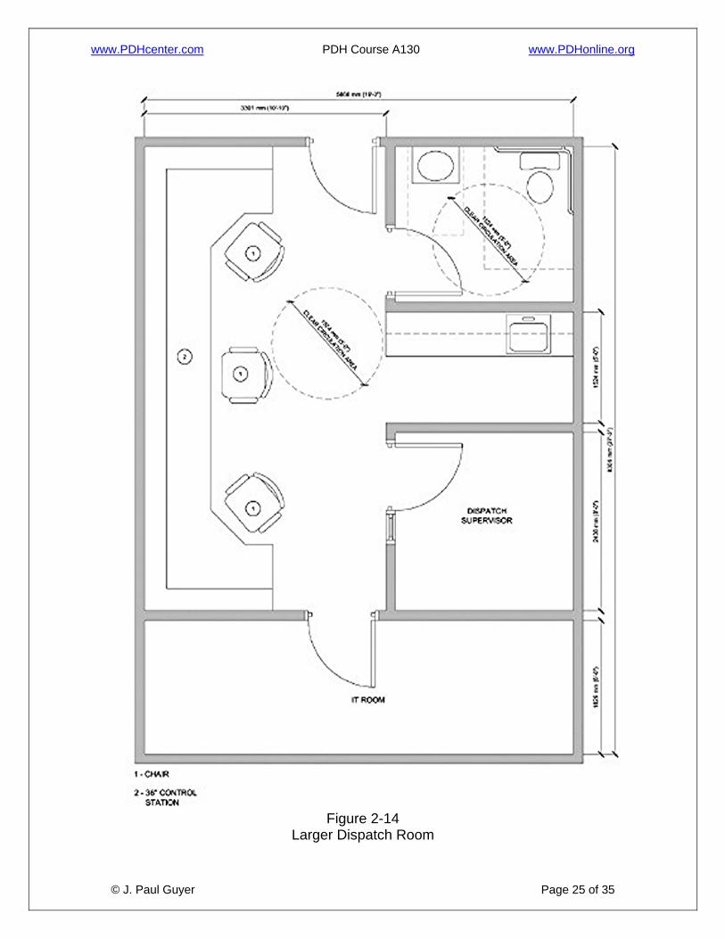
Figure 2-14
Larger Dispatch Room

www.PDHcenter.com PDH Course A130 www.PDHonline.org
© J. Paul Guyer Page 26 of 35
Figure 2-15 Day Room

www.PDHcenter.com PDH Course A130 www.PDHonline.org
© J. Paul Guyer Page 27 of 35
Figure 2-16 Day Room - Kitchen

www.PDHcenter.com PDH Course A130 www.PDHonline.org
© J. Paul Guyer Page 28 of 35
Figure 2-17 Day Room – Dining/Training Area

www.PDHcenter.com PDH Course A130 www.PDHonline.org
© J. Paul Guyer Page 29 of 35
Figure 2-18 Day Room – Living Room Area

www.PDHcenter.com PDH Course A130 www.PDHonline.org
© J. Paul Guyer Page 30 of 35
Figure 2-19
Dorm Room – One Bed
Figure 2-20
Dorm Room – Two Beds

www.PDHcenter.com PDH Course A130 www.PDHonline.org
© J. Paul Guyer Page 31 of 35
Figure 2-21 Dorm Room with Two Foldup Beds
www.PDHcenter.com PDH Course A130 www.PDHonline.org
© J. Paul Guyer Page 32 of 35
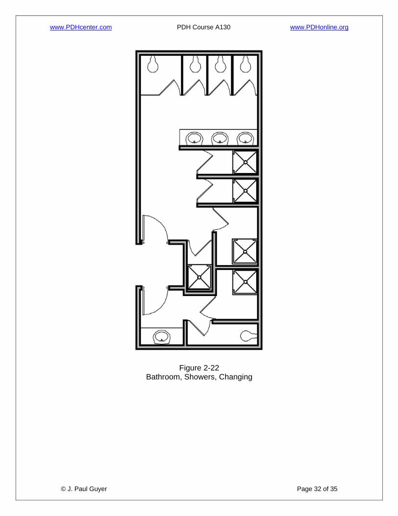
Figure 2-22 Bathroom, Showers, Changing
www.PDHcenter.com PDH Course A130 www.PDHonline.org
© J. Paul Guyer Page 33 of 35
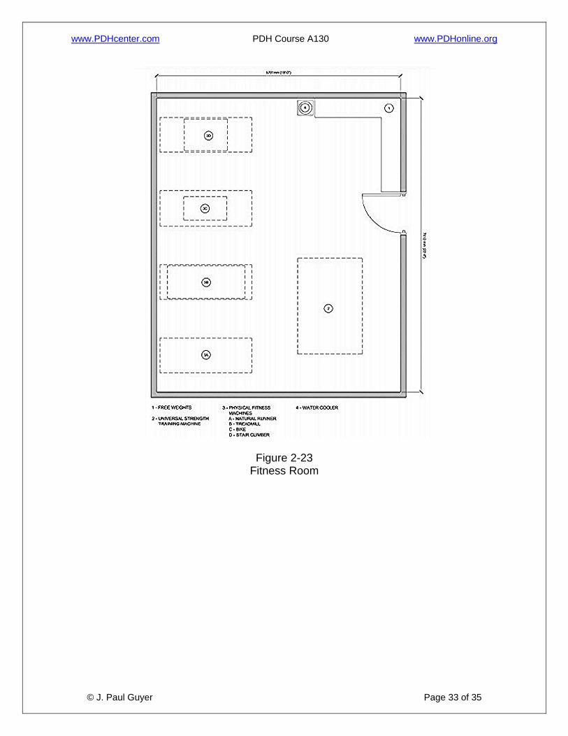
Figure 2-23 Fitness Room
www.PDHcenter.com PDH Course A130 www.PDHonline.org
© J. Paul Guyer Page 34 of 35
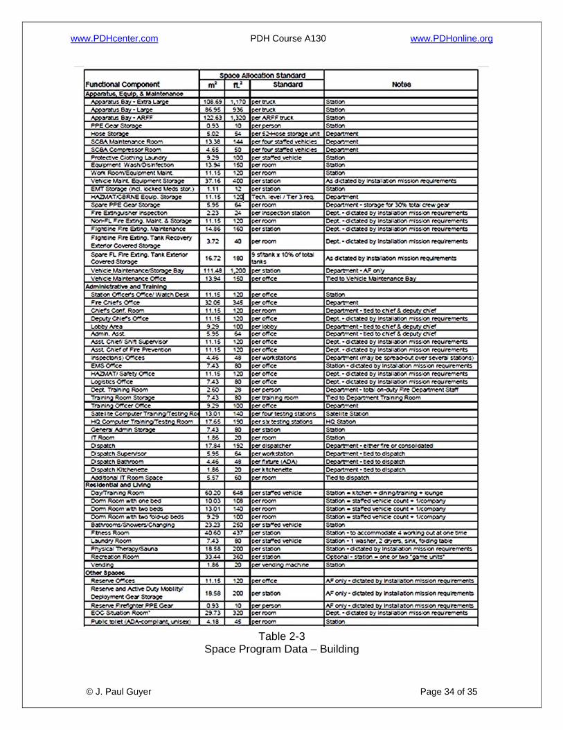
Table 2-3
Space Program Data – Building

www.PDHcenter.com PDH Course A130 www.PDHonline.org
© J. Paul Guyer Page 35 of 35
Table 2-4 Space Program Data - Site