an introduction to generator voltage, station service and ... · mechanical engineer, fire...
TRANSCRIPT
J. Paul Guyer, P.E., R.A. Editor Paul Guyer is a registered civil engineer, mechanical engineer, fire protection engineer and architect with 35 years of experience designing buildings and related infrastructure. For an additional 9 years he was a principal staff advisor to the California Legislature on capital outlay and infrastructure issues. He is a graduate of Stanford University and has held numerous national, state and local offices with the American Society of Civil Engineers, Architectural Engineering Institute and National Society of Professional Engineers. He is a Fellow of ASCE and AEI.
An Introduction to Generator Voltage, Station Service and Control Systems for Hydroelectric Power Plants

An Introduction to Generator Voltage, Station Service and
Control Systems for Hydroelectric Power Plants
J. Paul Guyer, P.E., R.A.
Editor
The Clubhouse Press El Macero, California


CONTENTS
1. GENERATOR VOLTAGE SYSTEM
2. STATION SERVICE SYSTEM
3. CONTROL SYSTEM
(This publication is adapted from the Unified Facilities Criteria of the United States government which are in the public domain, have been authorized for unlimited distribution, and are not copyrighted.) (Figures, tables and formulas in this publication may at times be a little difficult to read, but they are the best available. DO NOT PURCHASE THIS PUBLICATION IF THIS LIMITATION IS UNACCEPTABLE TO YOU.)


© J. Paul Guyer 2015 1
1. GENERATOR-VOLTAGE SYSTEM
1.1 GENERAL The generator-voltage system described in this discussion includes the
leads and associated equipment between the generator terminals and the low-voltage
terminals of the generator stepup (GSU) transformers, and between the neutral leads of
the generator and the power plant grounding system. The equipment generally
associated with the generator-voltage system includes switchgear; instrument
transformers for metering, relaying, and generator excitation systems; neutral grounding
equipment; and surge protection equipment. The equipment is classified as medium-
voltage equipment.
1.2 GENERATOR LEADS
1.2.1 GENERAL. The term “generator leads” applies to the circuits between the
generator terminals and the low voltage terminals of the GSU transformers. The
equipment selected depends upon the distance between the generator and transformer,
the capacity of the generator, the type of generator breakers employed, and the
economics of the installation. There are two general classes of generator leads: those
consisting of metal-enclosed buses and those consisting of medium-voltage cables. The
two classes, their advantages, disadvantages, and selection criteria are discussed in
the following subparagraphs. b. Metal-enclosed buses. There are three categories of
metal-enclosed bus: nonsegregated-phase, segregated phase, and isolated-phase.
Each type has specific applications dependent mainly on current rating and type of
circuit breaker employed with the bus.
1.2.2 NONSEGREGATED-PHASE BUSES. All phase conductors are enclosed in a
common metal enclosure without barriers, with phase conductors insulated with molded
material and supported on molded material or porcelain insulators. This bus
arrangement is normally used with metal-clad switchgear and is available in ratings up
to 4,000 A (6,000 A in 15-kV applications) in medium-voltage switchgear applications.

© J. Paul Guyer 2015 2
1.2.3 SEGREGATED-PHASE BUSES. All phase conductors are enclosed in a common
enclosure, but are segregated by metal barriers between phases. Conductor supports
usually are of porcelain. This bus arrangement is available in the same voltage and
current ratings as nonsegregated phase bus, but finds application where space
limitations prevent the use of isolated-phase bus or where higher momentary current
ratings than those provided by the nonsegregated phase are required.
1.2.4 ISOLATED-PHASE BUSES. Each phase conductor is enclosed by an individual
metal housing, which is separated from adjacent conductor housings by an air space.
Conductor supports are usually of porcelain. Bus systems are available in both
continuous and noncontinuous housing design. Continuous designs provide an
electrically continuous housing, thereby controlling external magnetic flux.
Noncontinuous designs provide external magnetic flux control by insulating adjacent
sections, providing grounding at one point only for each section of the bus, and by
providing shorting bands on external supporting steel structures. Noncontinuous
designs can be considered if installation of the bus will be at a location where
competent field welders are not available. However, continuous housing bus is
recommended because of the difficulty in maintaining insulation integrity of the
noncontinuous housing design during its service life. Isolated-phase bus is available in
ratings through 24,000 A and is associated with installations using station cubicle
switchgear (see discussion in paragraph 6-7b).
1.3 METAL-ENCLOSED BUS APPLICATION CRITERIA.
1.3.1 FOR MOST MAIN UNIT APPLICATIONS, the metal enclosed form of generator
leads is usually preferred, with preference for the isolated-phase type for ratings above
3,000 A. Enclosed buses that pass through walls or floors should be arranged so as to
permit the removal of housings to inspect or replace insulators.

© J. Paul Guyer 2015 3
1.3.2 ON ISOLATED-PHASE BUS RUNS (termed “delta bus”) from the generators to a
bank of single-phase GSU transformers, layouts should be arranged to use the most
economical combination of bus ratings and lengths of single-phase bus runs. The runs
(“risers”) to the single phase transformers should be sized to carry the current
corresponding to the maximum kVA rating of the transformer.
1.3.3 METAL-ENCLOSED BUS connections to the GSU transformer that must be
supported at the point of connection to the transformer should have accommodations
permitting the bus to be easily disconnected should the transformer be removed from
service. The bus design should incorporate weather-tight closures at the point of
disconnection to prevent moisture from entering the interior of the bus housing.
1.3.4 ON ALL ENCLOSED BUS RUNS, requirements for enclosing the connections
between the bus and the low voltage bushings of the GSU transformer should be
coordinated and responsibilities for scopes of supply clearly defined between
transformer supplier and bus supplier. Details of the proposed design of the connector
between the GSU transformer bushing terminals and the bus terminal should be
evaluated to ensure probability of reliable service life of the connection system.
1.4 INSULATED CABLES.
1.4.1 CABLES MAY BE APPROPRIATE for some small generators or in installations
where the GSU transformer is located in the plant’s switchyard. In the latter situation,
economic and technical evaluations should be made to determine the most practical
and cost-effective method to make the interconnection. Cables, if used, should have
copper conductors. Acceptable cable types include: (a) Single conductor, ethylene-
propylene-rubber (EPR) insulated, with non-PVC jacket. (b) Multi-conductor, ethylene-
propylene-rubber (EPR) insulated cables, with aluminum or steel sheath, and non- PVC
jacket, in multiple if necessary to obtain capacity. (c) Oil-pipe cable systems.

© J. Paul Guyer 2015 4
1.4.2 OIL-FILLED CABLE TERMINATIONS with cables terminated with a conductor
lug and a stress cone should be used for terminating oil-pipe cable systems. Cold shrink
termination kits should be used for terminating single and multi-conductor EPR cables.
Termination devices and kits should meet the requirements of IEEE 48 for Class I
terminations.
1.4.3 WHEN CABLES OF ANY TYPE are run in a tunnel, the effect of cable losses
should be investigated to determine the safe current-carrying capacity of the cable and
the extent of tunnel ventilation required to dissipate the heat generated by these losses.
Locations where hot spots may occur, such as risers from the tunnel to equipment or
conduit exposed to the sun, should be given full consideration.
1.5 NEUTRAL GROUNDING EQUIPMENT. Equipment between the generator neutral
and ground should, insofar as practicable, be procured along with the generator main
leads and switchgear. The conductor may be either metal-enclosed bus or insulated
cable in nonmagnetic conduit. Generator characteristics and system requirements
determine whether the machine is to be solidly grounded through a circuit breaker
(usually not possible), through a circuit breaker and reactor (or resistor), or through a
disconnecting switch and a distribution type of transformer. Solidly grounded systems
do not find wide application because resulting fault currents initiated by a stator to
ground fault are much higher than currents produced by alternative neutral grounding
systems. Higher ground fault currents lead to higher probability of damage to the stator
laminations of the connected generator. If a circuit breaker is used in the grounding
scheme, it can be either a single-pole or a standard 3-pole air circuit breaker with poles
paralleled to form a single-pole unit. Suitable metal enclosures should be provided for
the reactors, resistors, or grounding transformers used in the grounding system.
1.6 INSTRUMENT TRANSFORMERS
1.6.1 GENERAL. The instrument transformers required for the unit control and
protective relaying are included in procurements for metal-clad switchgear breakers that

© J. Paul Guyer 2015 5
are to be employed for generator switching. The instrument transformers are mounted
in the switchgear line-up with potential transformers mounted in draw-out compartments
for maintenance and service. Current transformers for the GSU transformer zone
differential relay are also mounted in the metal-clad switchgear cubicles. In isolated-
phase bus installations, the instrument transformers are included in procurement for the
isolated-phase bus. The current transformers, including those for generator differential
and transformer differential protection, are mounted “in-line” in the bus with terminations
in external terminal compartments. Required potential transformers are mounted in
dedicated compartments tapped off the main bus leads. The dedicated compartments
also contain the generator surge protection equipment (see Chapter 3, “Generators”).
Specified accuracy classes for instrument transformers for either type of procurement
should be coordinated with the requirements of the control, protective relaying, and
metering systems. Instrument transformers for the generator excitation system should
be included in the appropriate procurement.
1.6.2 CURRENT TRANSFORMERS. Current transformers of the multiple secondary
type are usually required and are mounted in the isolated-phase bus or in the metal-clad
switchgear to obtain the necessary secondary circuits within a reasonable space.
Current transformers in the neutral end of the generator windings are usually mounted
in the generator air housing. Accessibility for shortcircuiting the secondary circuits
should be considered in the equipment layout. The current transformers should be
designed to withstand the momentary currents and shortcircuit stresses for which the
bus or switchgear is rated.
1.6.3 POTENTIAL TRANSFORMERS. The potential transformers for metering and for
excitation system service are housed in separate compartments of the metal-clad
switchgear. If station cubicle breakers or isolated-phase bus are involved, a special
cubicle for potential transformers and surge protection equipment is provided in a
variety of arrangements to simplify generator lead connections. Potential transformers
should be protected by current limiting resistors and fuses. Draw-out type mountings are
standard equipment in metal-clad switchgear. Similar arrangements are provided in

© J. Paul Guyer 2015 6
cubicles associated with isolated-phase bus. Cubicles with the isolated-phase buses
also provide phase isolation for transformers.
1.7 SINGLE UNIT AND SMALL POWER PLANT CONSIDERATIONS. When metal-
clad switchgear is used for generators in small plants (having typically one or two
generators of approximately 40,000 kW or less) the switchgear may be equipped with
indicating instruments, control switches, and other unit control equipment (e.g.,
annunciators and recorders) mounted on the switchgear cell doors. This arrangement
can take the place of a large portion of the conventional control switchboard. The
switchgear may be located in a control room, or the control room omitted entirely,
depending upon the layout of the plant. Current philosophy is to make the smaller plants
suitable for unmanned operation, and remote or automatic control. This scheme
eliminates the need for a control room. Arrangements for control equipment with this
type of scheme are described in more detail in Chapter 8, “Control System.”
1.8 EXCITATION SYSTEM POWER POTENTIAL TRANSFORMER. The power
potential transformer (PPT) is fed from the generator leads. The PPT is procured as part
of the excitation system equipment. The PPT should be a three phase, 60-Hz, self-
cooled, ventilated dry type transformer. The PPT is generally tapped at the generator
bus with primary current limiting fuses, designed for floor mounting, and with a low-
voltage terminal chamber with provisions for terminating the bus or cable from the
excitation system power conversion equipment.
1.9 CIRCUIT BREAKERS
1.9.1 GENERAL. The particular switching scheme selected from those described
includes the generator voltage and capacity rating, and results from fault studies will
determine the type of generator breaker used for switching, together with its continuous
current rating and short-circuit current rating. If a “unit” switching scheme is chosen with
switching on the high side of the GSU transformer, then criteria regarding high-voltage
power circuit breakers are used to select an appropriate breaker. If a generator-voltage

© J. Paul Guyer 2015 7
switching scheme is selected, then criteria outlined in this paragraph should be used for
breaker selection.
1.9.2 GENERATOR-VOLTAGE CIRCUIT BREAKER TYPES.
1.9.2.1 WHEN GENERATOR-VOLTAGE CIRCUIT BREAKERS are required, they are
furnished in factory-built steel enclosures in one of three types. Each type of circuit
breaker has specific applications dependent on current ratings and short-circuit current
ratings. In general, Table 6-1 provides a broad overview of each breaker type and its
range of application for generator switching. The three types are as follows: (a) Metal-
clad switchgear. Metal-clad switchgear breakers can be used for generator switching on
units of up to 45 MVA at 13.8 kV, depending on interrupting duty requirements. Either
vacuum interrupters or SF6 interrupting mediums are permitted by the guide
specification. (b) Station-type cubicle switchgear. Station-type breakers can be used in
generator switching applications on units of approximately 140 MVA. Details of
construction are covered in IEEE C37.20.2. For SF6 circuit breakers, the insulating and
arc-extinguishing medium is the gas. For indoor equipment, in areas not allowed to
reach temperatures at or near freezing, the gas will probably not require heating
provisions. However, special care and handling is needed for SF6 gas. (c) In-line
isolated-phase bus breakers. For high current, medium-voltage, generator breaker
applications, i.e., 15 kV, 6,000 Amp or higher, in-line breakers mounted in the isolated-
phase bus system have been employed on high-capacity systems. These breakers
employ either SF6 or compressed air insulating and arc extinguishing systems and can
incorporate breaker isolating switches in the breaker compartment. This type of breaker
requires less space than a station type cubicle breaker but has higher initial cost. It
should receive consideration where powerhouse space is at a premium. Technical
operating parameters and performance are covered in IEEE C37.013.
1.9.2.2 THE ESSENTIAL FEATURES OF DRAW-OUT METAL-CLAD switchgear and
station type cubicle switchgear are covered in IEEE C37.20.2. Essential features of in-
line isolated phase bus-type circuit breakers are covered in IEEE C37.013 and C37.23.

© J. Paul Guyer 2015 8
Specific current and interrupting ratings available at other voltages are summarized in
Tables 6-2 and 6-3.
Table 6-1
Generator Breaker Application Table, 13.8-kV Application
Table 6-2
Indoor Metal-Clad Switchgear, Removable Breaker Nominal Ratings

© J. Paul Guyer 2015 9
Table 6-3
Indoor Metal-Enclosed Switchgear, Fixed Breaker Preferred Ratings For Generator
Circuit Breakers 4/

© J. Paul Guyer 2015 10
2. STATION SERVICE SYSTEM
2.1 POWER SUPPLY
2.1.1 GENERAL. A complete station service supply and distribution system should be
provided to furnish power for station, dam auxiliaries, lighting, and other adjacent
features of the project. The loss of a station service source, either through switching
operations or due to protective relay action, should not leave the plant without service
power. The station service system should have a minimum of two full-capacity,
redundant power sources.
2.1.2 PLANT “BLACK START” CAPABILITY.
2.1.2.1 GENERAL. “BLACK START” CAPABILITY is desirable at hydro plants since
the plants can assist in re-establishing generation for the power system in an
emergency. “Black start” capability is defined as the ability of the plant, without an
external source of power, to maintain itself internally, start generating units, and bring
them up to speed-no-load conditions, close the generator breakers, energize
transformers and transmission lines, perform line charging as required, and maintain
units while the remainder of the grid is re-established. The plant must then
resynchronize to the grid.
2.1.2.2 POWER SYSTEM PROBLEMS. (a) There are a number of circumstances that
can lead to collapse of all or parts of a bulk power distribution system. Regardless of the
circumstances, the triggering event generally leads to regional and subregional
mismatch of loads and generation and “islanding” (i.e., plants providing generation to
isolated pockets of load). Separation of generation resources from remote loads and
“islanding” can cause voltage or frequency excursions that may result in the loss of
other generation resources, particularly steam generation, which is more sensitive to
frequency excursions than hydroelectric turbine generators. Steam generation is also
harder to return to service than hydro generation, so the burden of beginning system
© J. Paul Guyer 2015 11
restoration is more likely to fall on hydro resources. (b) When a transmission line is
removed from service by protective relay action, the power it was carrying will either
seek another transmission line route to its load, or be interrupted. If its power is shifted
to other transmission lines, those lines can become overloaded and also be removed
from service by protective relays. System failures are more likely to happen during
heavy load periods, when failures cascade because of stress on the system. If the
hydro units are running at or near full load when the plant is separated from the system,
they will experience load rejections. (c) Units subjected to a load rejection are designed
to go to speed-no-load until their operating mode is changed by control action.
Sometimes, however, they shut down completely, and if station service is being
supplied by a unit that shuts down, that source will be lost. Units can’t be started, or
kept on line, without governor oil pressure, and governor oil pressure can’t be
maintained without a source of station service power for the governor oil pumps. (d)
Assumptions made concerning plant conditions when the transmission grid collapses,
thus initiating the need for a “black start,” will define the equipment requirements and
operating parameters which the station service design must meet. At least one
emergency power source from an automatic start-engine-driven generator should be
provided for operating governor oil pumps and re-establishing generation after losing
normal station service power.
2.1.3 FOR LARGE POWER PLANTS.
2.1.3.1 TWO STATION SERVICE TRANSFORMERS with buses and switching
arranged so that they can be supplied from either the main generators or the
transmission system should be provided, with each transformer capable of supplying
the total station load. A unit that will be operated in a base load mode should be
selected to supply a station service transformer, if possible. Station service source
selection switching that will allow supply from either a main unit or the power system
should be provided. The switching should be done by interlocked breakers to prevent
inadvertent parallel operation of alternate sources. If a main unit is switched on as a
source, then the supply should not depend on that unit being connected to the power

© J. Paul Guyer 2015 12
system. If the power system is switched on as the source, then the supply should not
depend on any units being connected to the power system.
2.1.3.2 TO MEET FEDERAL ENERGY REGULATORY COMMISSION (FERC)
requirements, all reservoir projects should be equipped with an engine-driven generator
for emergency standby service with sufficient capacity to operate the spillway gate
motors and essential auxiliaries in the dam. The unit is usually installed in or near the
dam rather than in the powerhouse. It may also be used to provide emergency service
to the powerhouse, although the use of long supply cables from the dam to the
powerhouse could be a disadvantage.
2.1.3.3 FOR A LARGE POWER PLANT, a second automatic start emergency power
source may be required in the powerhouse. Besides diesel engine-generators, small
combustion turbines are an option, although they are more complex and expensive than
diesel engine-generator sets.
2.1.3.4 ANY EMERGENCY source should have automatic start control. The source
should be started whenever station service power is lost. The emergency source control
should also provide for manual start from the plant control point. It is also important to
provide local control at the emergency source for non-emergency starts to test and
exercise the emergency source. A load shedding scheme may be required for any
emergency source, if the source capacity is limited.
2.1.4 FOR SMALL, ONE-UNIT POWER PLANTS. One station service transformer
supplied from the transmission system should be provided for a normal station service
bus, and an emergency station service bus should be supplied from an engine-driven
generator. The emergency source should have sufficient capacity to operate the
spillway gate motors and minimum essential auxiliaries in the dam and powerhouse
such as unwatering pumps, governor oil pumps, and any essential preferred AC loads.
e. Station service distribution system.

© J. Paul Guyer 2015 13
2.1.4.1 IN MANY PLANTS, feeders to the load centers can be designed for 480-V
operation. In a large plant, where large loads or long feeder lengths are involved, use of
13.8-kV or 4.16-kV distribution circuits will be satisfactory when economically justified.
Duplicate feeders (one feeder from each station service supply bus) should be provided
to important load centers. Appropriate controls and interlocking should be incorporated
in the design to ensure that critical load sources are not supplied from the same bus.
Feeder interlock arrangements, and source transfer, should be made at the feeder
source and not at the distribution centers.
2.1.4.2 THE DISTRIBUTION SYSTEM control should be thoroughly evaluated to
ensure that all foreseeable contingencies are covered. The load centers should be
located at accessible points for convenience of plant operation and accessibility for
servicing equipment. Allowance should be made for the possibility of additional future
loads.
2.1.4.3 ALL OF THE AUXILIARY EQUIPMENT for a main unit is usually fed from a
motor control center reserved for that unit. Feeders should be sized based on maximum
expected load, with proper allowance made for voltage drop, motor starting inrush, and
to withstand short-circuit currents. Feeders that terminate in exposed locations subject
to lightning should be equipped with surge arresters outside of the building.
2.1.4.4 THREE-PHASE, 480-V STATION SERVICE SYSTEMS using an ungrounded-
delta phase arrangement have the lowest first cost. Such systems will tolerate, and
allow detection of, single accidental grounds without interrupting service to loads.
Three-phase, grounded-wye arrangements find widespread use in the industrial sector
and with some regulatory authorities because of perceived benefits of safety, reliability,
and lower maintenance costs over a 480-V delta system. Industrial plants also have a
higher percentage of lighting loads in the total plant load. Installation costs for providing
service to large concentrations of high-intensity lighting systems are lower with 480/277-
V wye systems. Delta systems are still preferred in hydro stations because of the
© J. Paul Guyer 2015 14
cleaner environment, good service record, and skilled electricians available to maintain
the system.
2.1.5 STATION SERVICE SWITCHGEAR.
2.1.5.1 METAL-CLAD SWITCHGEAR with SF6 or vacuum circuit breakers should be
supplied for station service system voltage above 4.16 kV. Metal-enclosed switchgear
with 600-V drawout air circuit breakers should be used on 480-V station service
systems. The switchgear should be located near the station service transformers.
2.1.5.2 THE STATION SERVICE SWITCHGEAR should have a sectionalized bus, with
one section for each normal station service source. Switching to connect emergency
source power to one of the buses, or selectively, to either bus should be provided. If the
emergency source is only connected to one bus, then the reliability of the station service
source is compromised since the bus supplied from the emergency source could be out
of service when an emergency occurred. It is preferable that the emergency source be
capable of supplying either bus, with the breakers interlocked to prevent parallel
operation of the buses from the emergency source.
2.1.5.3 EACH SUPPLY AND BUS TIE BREAKER should be electrically operated for
remote operation from the control room in attended stations. As a minimum, bus voltage
indication for each bus section should be provided at the remote point where remote
plant operation is provided. Transfer between the two normal sources should be
automatic. Transfer to the emergency power sources should also be automatic when
both normal power sources fail. Feeder switching is performed manually except for
specific applications.
2.1.5.4 IN LARGE STATION SERVICE SYSTEMS with a double bus arrangement,
source/bus tie breakers should be located at each end of the switchgear compartment.
The source/bus tie breakers should not be located in adjacent compartments because a
catastrophic failure of one breaker could destroy or damage adjacent breakers leading

© J. Paul Guyer 2015 15
to complete loss of station service to the plant. In large plants where there is sufficient
space, it is even safer to provide a separate, parallel cubicle lineup for each station
service bus for more complete physical isolation. Even with this arrangement, feeder
and tie breakers should not be located in adjacent compartments.
2.1.5.5 FOR 480-V STATION SERVICE SYSTEMS, a delta connected, ungrounded
system is recommended for the following reasons: (a) Nature of the loads. The load in a
hydroelectric power plant is made up predominantly of motor loads. In a commercial or
light industrial facility, where the load is predominantly lighting, the installation of a
480/277 V, wye-connected system is more economical due to the use of higher voltages
and smaller conductor sizes. These economies are not realized when the load is
predominantly motor loads. For high bay lighting systems, certain installation economies
may be realized through the use of 480/277-V wye-connected subsystems. (b) Physical
circuit layout. Wye-connected systems allow the ability to quickly identify and locate a
faulted circuit in a widely dispersed area. Although hydroelectric power plants are widely
dispersed, the 480-V system is concentrated in specific geographic locales within the
plant, allowing rapid location of a faulted circuit, aided by the ground detection system.
2.2 RELAYS. An overlapping protected zone should be provided around circuit
breakers. The protective system should operate to remove the minimum possible
amount of equipment from service. Overcurrent relays on the supply and bus tie
breakers should be set so feeder breakers will trip on a feeder fault without tripping the
source breakers. Ground overcurrent relays should be provided for wye-connected
station service systems. Ground detection by a voltage relay connected in the broken
delta corner of three potential transformers should be provided for ungrounded or delta-
connected systems (ANSI C37.96). Bus differential relays should be provided for station
service systems of 4.16 kV and higher voltage. The adjustable tripping device built into
the feeder breaker is usually adequate for feeder protection on station service systems
using 480-V low-voltage switchgear.
© J. Paul Guyer 2015 16
2.3 CONTROL AND METERING EQUIPMENT. Indicating instruments and control
should be provided on the station service switchgear for local control. A voltmeter, an
ammeter, a wattmeter, and a watthour meter are usually sufficient. A station service
annunciator should be provided on the switchgear for a large station service system.
Contact-making devices should be provided with the watthour meters for remote
indication of station service energy use. Additional auxiliary cabinets may be required
for mounting breaker control, position indication, protective relays, and indicating
instruments. For large plants, physical separation of control and relay cubicles should
be considered so control and relaying equipment will not be damaged or rendered
inoperable by the catastrophic failure of a breaker housed in the same or adjacent
cubicle.
2.4 LOAD/DISTRIBUTION CENTERS. Protective and control devices for station
auxiliary equipment should be grouped and mounted in distribution centers or,
preferably, motor control centers. The motor starters, circuit breakers, control switches,
transfer switches, etc., should all be located in motor control centers.
2.5 ESTIMATED STATION SERVICE LOAD
2.5.1 GENERAL.
2.5.1.1 THE MAXIMUM DEMAND that is expected on the station service system is the
basis for developing station service transformer ratings. The expected demand may be
determined from a total of the feeder loads with an appropriate diversity factor, or by
listing all connected loads and corresponding demand loads in kVA. A diversity factor
smaller than 0.75 should not be used. During high activity periods or plant emergencies,
higher than normal station service loads can be expected and if a small diversity factor
has been used, the system may not have adequate capacity to handle its loads.
2.5.1.2 DEMAND FACTORS USED FOR DEVELOPING station service equipment
capacities can vary widely due to the type of plant (high head stand-alone power plant

© J. Paul Guyer 2015 17
versus low head power plant integrated with a dam structure and navigation lock).
Development of demand factors for unit auxiliaries should account for the type of
auxiliaries in the plant based on trends observed at similar plants. For instance, the
governor oil pump demand for a Kaplan turbine will be greater than that for the governor
oil pump demand for a Francis turbine of the same output rating because of the
additional hydraulic capacity needed to operate the Kaplan turbine blades. If the plant is
base loaded, governor oil pumps will not cycle as often as governor oil pumps in a
similar plant used for automatic generation control or peaking service.
2.5.1.3 STATION SERVICE SYSTEMS should be designed to anticipate load growth.
Anticipated growth will depend on a number of factors including size of the plant,
location, and whether the plant will become an administrative center. A one- or two-unit
isolated plant not suitable for addition of more units would not be expected to
experience a dramatic increase in demand for station service power. For such a plant, a
contingency for load growth of 20 percent would be adequate. Conversely, some large
multi-purpose plants have experienced 100-percent increases in the connected kVA
loads on the station service system over original design requirements.
2.5.1.4 CAPACITY DEFICITS IN EXISTING STATION service systems have not been
caused by the designer’s inability to predict unit auxiliary requirements, but by
unforeseeable demands to provide service for off-site facilities added to multipurpose
projects. Examples of this have been the development of extensive maintenance and
warehouse facilities outside the power plant, or electrical requirements resulting from
environmental protection issues such as fish bypass equipment. The station service
design should have provisions for unanticipated load growth for multipurpose projects
with navigation locks and fish ladders. For such projects, a minimum growth factor
contingency adder of 50 percent could be justified. b. Auxiliary demand. Demand varies
greatly with different auxiliaries, and the selection of demand factors requires
recognition of the way various power plant equipment will be operated. One method
illustrated in Table 7-1 assumes 1 hp as the equivalent of 1 kVA and on lights and
heaters uses the kW rating as the kVA equivalent. The accuracy of the method is within
© J. Paul Guyer 2015 18
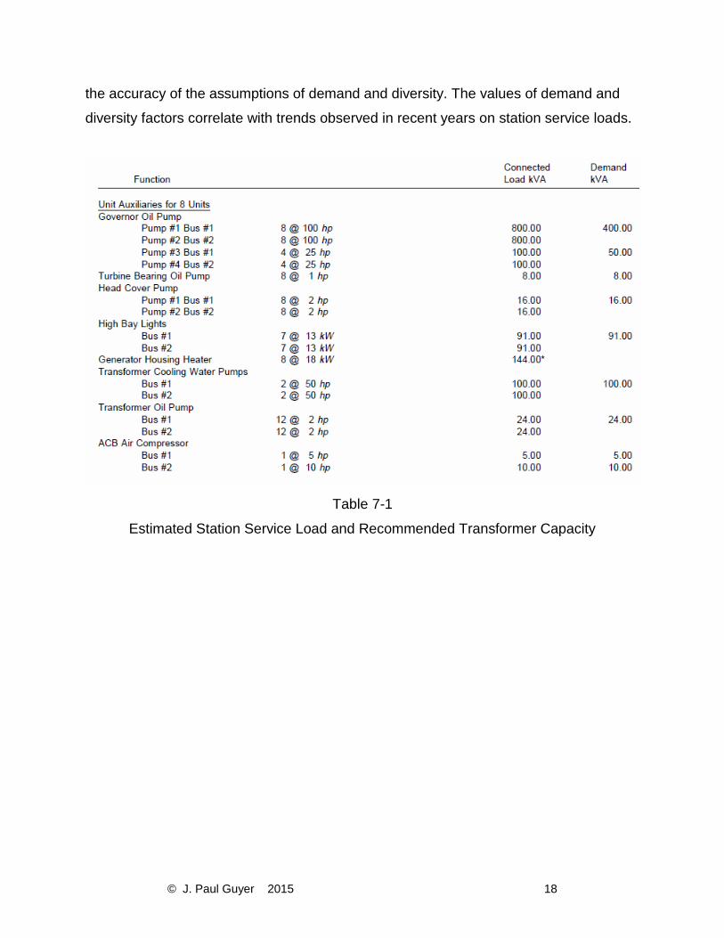
the accuracy of the assumptions of demand and diversity. The values of demand and
diversity factors correlate with trends observed in recent years on station service loads.
Table 7-1
Estimated Station Service Load and Recommended Transformer Capacity

© J. Paul Guyer 2015 19
Table 7-1 (continued)
Estimated Station Service Load and Recommended Transformer Capacity

© J. Paul Guyer 2015 20
3. CONTROL SYSTEM
3.1 GENERAL
3.1.1 SCOPE. The control system as discussed in this chapter deals with equipment for
the control and protection of apparatus used for power generation, conversion, and
transmission. It does not include low-voltage panelboards and industrial control
equipment as used with plant auxiliaries. IEEE 1010 and EPRI EL-5036, Volume 10,
provide guidelines for planning and designing control systems for hydroelectric power
plants.
3.1.2 CONTROL SYSTEM COMPONENTS. The control system consists primarily of a
computer-based control system, hard-wired logic or programmable logic, indicating and
recording instruments, control switches, protective relays, and similar equipment. The
greatest part of this equipment should be grouped at one location to facilitate
supervision and operation of the main generating units, transmission lines, and station
auxiliaries. The grouping of these controls at one location within the confines of the
power plant is termed “centralized control.”
3.1.3 START-STOP SEQUENCE. Each generator unit control system should be
provided with a turbine/generator start-stop sequencing logic using a master relay
located at the generator (or unit) switchboard. The starting sequence begins with pre-
start checks of the unit, followed by starting unit auxiliaries, and ends with the unit
operating under the speed-no-load condition. Manual or automatic synchronizing and
closure of the unit breaker can be performed at the local control location. The stopping
sequence should provide for four types of unit shutdown: protective relaying, operator’s
emergency stop switch, mechanical problems, and normal shutdown.
3.1.4 GENERATOR SWITCHBOARDS. Generator switchboards in larger power plants
are located near the controlled generator. The switchboards provide local control of the
unit. In smaller power plants, where metal-clad switchgear is used for switching the

© J. Paul Guyer 2015 21
generator, unit control equipment is located on auxiliary panels of the switchgear line-
up. Like the switchboards, the auxiliary panel equipment provides local control of the
unit.
3.1.5 AUXILIARY EQUIPMENT CONTROL. Large power plants using high-voltage
busing and switching or having an adjacent switchyard as part of the development
should have control for this equipment located in the grouping suggested in paragraph
8-1(b). Even though the controlled equipment is remote from the plant, the equipment is
not “offsite.” Offsite control denotes control from a location not resident to the plant, i.e.,
another plant or a control complex at another location.
3.1.6 CONTROL ROOM LOCATION. In plants with a few units, the control room
location with its centralized controls should provide ready access to the governor control
cabinets. In plants with ultimately four or more units, the control room should be located
near the center of the ultimate plant or at a location allowing ready access to the units
and adjacent switchyard. The relative number and lengths of control circuits to the units
and to the switchyard is a factor to consider, but is secondary to consideration of
operating convenience. The control room should be an elevation above maximum high
water, if there is any danger that the plant may be flooded. A decision on the location of
the control room should be reached at an early stage of plant design, since many other
features of the plant are affected by the control room location. Control location
definitions and control modes are further described in IEEE 1010. g. Smaller plants. In
smaller power plants, where indoor generator-voltage busing and switching are used,
hinged instrument panels on the switchgear cubicles should be used as mounting space
for main control equipment. This results in the main group of control equipment being
located at the main switchgear location.
3.2 CONTROL EQUIPMENT
3.2.1 GENERAL. Centralized automatic and manual control equipment should be
located in the control room of large power plants. The control console, in conjunction

© J. Paul Guyer 2015 22
with supervisory control and data acquisition (SCADA) equipment and the status
switchboard, enables the control room operator to control the powerhouse operation.
Equipment racks housing automatic synchronizing and centralized auxiliary equipment
should be located in or adjacent to the control room to facilitate connections with control
room equipment. If the plant is controlled from offsite, the plant’s SCADA equipment
should be located in or adjacent to the control room.
3.2.2 SPACE ALLOCATION. Space allotted for control equipment, whether in a
separate control room or in the main switchgear cubicle area, must be large enough to
accommodate the panels required for the ultimate number of generating units and
transmission lines. The space requirement, as well as the size and location of openings
required in the floor, should be provided to the architectural and structural designers to
ensure proper consideration in door, room, and floor slab designs.
3.2.3 CABINET CONSTRUCTION. Generator switchboard panels and doors should be
1/8-in. thick or No. 11 U.S.S. gauge smooth select steel with angle or channel edges
bent to approximately a 1/4-in. radius. Panels should be mounted on sills ready for
powerhouse installation in groups as large as can be shipped and moved into the
installation area. All equipment on the switchboards should be mounted and wired at the
factory, and the boards should be shipped to the powerhouse with all equipment in
place.
3.2.4 EQUIPMENT ARRANGEMENT. The arrangement of equipment on the control
switchgear, switchboard, or control console should be carefully planned to achieve
simplicity of design and to replicate unit control placements familiar to the intended
operating staff. Simplicity of design is a definite aid to operation and tends to reduce
operating errors; therefore, the relative position of devices should be logical and
uniform. Switchboard and control console design should be patterned after an
appropriate example to attain a degree of standardization in the arrangement of
indicating instruments and basic control switches. Control switches should be equipped
with distinctive handles as shown in Table 8-1. Each item of equipment should be

© J. Paul Guyer 2015 23
located by consideration of its functions, its relation to other items of equipment, and by
its use by the operator.
3.3 TURBINE GOVERNOR The digital governor electrical control cabinet usually is
located adjacent to the generator switchboard separate from the actuator cabinet. The
control cabinet contains governor electronic or digital “proportional-integral derivative”
(P-I-D) control components. The actuator cabinet housing the power hydraulics of the
governor system is located to minimize the pressure line runs between the turbine
servomotors, the actuator, and the governor pressure tank. For smaller capacity
governors and smaller plants, governor electronic and hydraulic controls are all located
in the governor actuator cabinet.
3.4 LARGE POWER PLANT CONTROL
3.4.1 GENERAL. Centralized control system equipment is located in the control room
and is interconnected to the generator switchboards located near the units. Required
control and monitoring of all functions of the hydroelectric power project are provided to
the operators. The control console with conventional control devices and monitoring
equipment in conjunction with a computer based data acquisition and control system
(DACS), provides control and indication access to individual items of equipment to
facilitate operation, supervision, and control. Hard-wired pushbutton switches provide
for direct operator manual control of unit start-stop, breaker close (initiating automatic
synchronizing), breaker trip, voltage, loading, and gate limit raise-lower. Analog or
digital panel meters and indicating lights continuously indicate the status of all main
units, breakers, transformers, and lines. The DACS system display monitors and
keyboards are available to operator control. The unit controls and instruments
supplement or duplicate those on the generator switchboard, and provide the control
room operator with the ability to transfer control of any selected unit or group of units to
the generator switchboard in case of system trouble. The control console may also
provide spillway gate control, fishway control, project communications, and other project
equipment control functions when required.
© J. Paul Guyer 2015 24
3.4.2 EQUIPMENT LOCATION. Arrangement of control and instrument switches and
mimic bus should simulate the relative order of interconnections or physical order of the
plant arrangement assisting the operator in forming a mental picture of connections.
The top of the control console panel should be inclined to provide easier access to the
control switches and to improve console visibility. Layouts of console visual display
terminals (VDTs) should follow applicable guidelines to ensure good visual acuity of the
displays. Panels of the control console should be arranged for ultimate development, so
that the addition of a control panel for another generator or another line will not disturb
existing equipment.
3.4.3 STATUS SWITCHBOARD. The status switchboard contains graphic and visual
indication, generator load recorders, station total megawatts and megavars recorders,
and other required project data displays. The status switchboard should be located for
easy observation from the control console. The status switchboard should be a standard
modular vertical rack enclosure joined together to form a freestanding, enclosed
structure.
3.4.4 EQUIPMENT RACKS. Equipment racks should be provided for mounting line
relays, automatic synchronizing equipment, the common and outside annunciator
chassis, auxiliary relays, communication equipment, and transfer trip equipment. The
equipment racks should be standard, modular, vertical rack enclosures.

© J. Paul Guyer 2015 25
Table 8-1
Typical Plant Control and lnstrumenl Switoh Data

© J. Paul Guyer 2015 26
3.4.5 SCADA EQUIPMENT. The SCADA and communication equipment should be
located in the general control area.
3.5 SMALL POWER PLANT CONTROL
3.5.1 GENERAL. Small power plants using medium-voltage metal-clad switchgear for
generator control impose different limitations on equipment arrangements than
arrangement limitations of generator switchboards for local unit control. This is due to
the variety of equipment available with switchgear and, consequently, the different
possibilities for locations for major control equipment. As noted in paragraph 8-1g,
hinged instrument p anels on the main switchgear can be used for control equipment.
Where space and switchgear construction allow, it is desirable to have hinged
instrument panels on the side of the stationary structure opposite the doors for removing
the breakers. These panels, however, provide space for only part of the necessary
control equipment, and one or more auxiliary switchgear compartments will be required
to accommodate the remaining equipment.
3.5.2 EQUIPMENT LOCATION. Annunciator window panels, indicating instruments,
control switches, and similar equipment should be mounted on the switchgear hinged
panels. The hinged panel for each breaker section should be assigned to the generating
unit, transmission line, or station service transformer that the breaker serves and only
the indicating instruments, control switches, etc., associated with the controlled
equipment mounted on the panel. A hinged synchronizing panel should be attached to
the end switchgear cubicle.
3.5.3 ADDITIONAL EQUIPMENT LOCATION. Protective relays, temperature
indicators, load control equipment, and other equipment needed at the control location
and not provided for on the switchgear panels should be mounted on the auxiliary
switchgear compartments.

© J. Paul Guyer 2015 27
3.5.4 SCADA EQUIPMENT. Small power plants are frequently unattended and
remotely controlled from an offsite location using SCADA equipment. The SCADA and
communication equipment should be located in the general control area.
3.6 PROTECTIVE RELAYS
3.6.1 GENERAL. The following discussion on protective relays includes those devices
which detect electrical faults or abnormal operating conditions and trip circuit breakers
to isolate equipment in trouble or notify the operator through alarm devices that
corrective action is required. The application of relays must be coordinated with the
partitioning of the electrical system by circuit breakers, so the least amount of
equipment is removed from operation following a fault, preserving the integrity of the
balance of the plant’s electrical system. (1) Generally, the power transmitting agency
protection engineer will coordinate with the Corps of Engineers protection engineer to
recommend the functional requirements of the overlapping zones of protection for the
main transformers and high voltage bus and lines. The Corps of Engineers protection
engineer will determine the protection required for the station service generators and
transformers, main unit generators, main transformers, and powerhouse bus. (2)
Electromechanical protective relays, individual solid state protective relays, multi-
function protective relays, or some combination of these may be approved as
appropriate for the requirements. Traditional electromechanical protective relays offer
long life but may malfunction when required to operate, while many less popular
designs are no longer manufactured. Individual solid state protective relays and/or multi-
function protective relays offer a single solution for many applications plus continuous
self-diagnostics to alarm when unable to function as required. Multi-function protective
relays may be cost-competitive for generator and line protection when many individual
relays would be required. When multifunction relays are selected, limited additional
backup relays should be considered based upon safety, the cost of equipment lost or
damaged, repairs, and the energy lost during the outage or repairs if appropriate. (3)
When the protection engineer determines that redundancy is required, a backup
protective relay with a different design and algorithm should be provided for reliability
© J. Paul Guyer 2015 28
and security. Fully redundant protection is rarely justified even with multi-function relay
applications. Generators, main transformers, and the high voltage bus are normally
protected with independent differential relays. (4) When the protective relays have been
approved, the protection engineer will provide or approve the settings required for the
application.
3.6.2 MAIN GENERATORS. (1) The general principles of relaying practices for the
generator and its excitation system are discussed in IEEE standards C37.101, C37.102,
and C37.106. Unless otherwise stated, recommendations contained in the above guides
apply to either attended or unattended stations. (2) Differential relays of the high speed,
percentage differential type are usually provided to protect the stator windings of
generators rated above 1500 kVA. (3) A high-impedance ground using a resistance
loaded distribution transformer scheme is generally used, thereby limiting generator
primary ground fault current to less than 25 A. A generator ground, AC overvoltage
relay with a third harmonic filter is connected across the grounding impedance to sense
zero-sequence voltage. If the generator is sharing a GSU transformer with another unit,
a timed sequential ground relay operation to isolate and locate generator and delta bus
grounds should be provided. (4) Out-of-step relays are usually provided to protect
generators connected to a 500-kV power system, because the complexity of a modern
EHV power system sometimes leads to severe system frequency swings, which cause
generators to go out of step. The generator out-of-step relays should incorporate an
offset mho and angle impedance relay system which can detect an out-of-step condition
when the swing locus passes through the generator or its transformer. (5) Frequency
relays, and under- and over-frequency protection, are not required for hydraulic-turbine-
driven generators. (6) Temperature relays are provided for thrust and guide bearings as
backup for resistance temperature detectors and indicating thermometers with alarms.
The relays are set to operate at about 105o C and are connected to shut down the unit.
Shutdown at 105o C will not save the babbitt on the bearing but will prevent further
damage to the machine.
3.6.2 GENERATOR BREAKERS.

© J. Paul Guyer 2015 29
3.6.2.1 MOST BREAKER FAILURE RELAYING schemes operate on high phase or
ground currents. When a trip signal is applied to the breaker, the breaker should open
and current flow should cease within the breaker interrupting time. The breaker failure
relay is usually applied to operate lockout relays to trip backup breakers after a time
delay based on the assumption the breaker has failed if current flow continues after the
breaker trip circuit has been energized. These schemes do not provide adequate
protection if breaker failure occurs while current is near zero immediately following
synchronizing.
3.6.2.2 ANOTHER SCHEME USES A BREAKER auxiliary contact to detect breaker
failure with fault detectors for phase current balance, reverse power, and overcurrent
relays. Protective relay contact closing or operation of the breaker control switch to the
trip position energizes a timing relay. If the breaker auxiliary contact does not close
within the breaker interrupting time, the timing relay will close its contacts, enabling the
phase current balance, reverse power, and overcurrent relays to perform the required
trip functions.
3.6.2.3 SOME BREAKER CONTROL SYSTEMS monitor the breaker trip coil using a
high resistance coil relay connected in series with the trip coil. A time delay relay is
required to allow the breaker to open during normal tripping without initiating an alarm.
3.6.3 PROVISION SHOULD BE MADE to trip generator breakers when there is a loss
of the breaker trip circuit DC control power or complete loss of DC for the entire plant. A
stored energy capacitor trip device can be used to trip the breaker in case of a loss of
control power.
3.6.4 TRANSFORMER PROTECTION. (1) Transformers or transformer banks over
1500 kVA should be protected with high-speed percentage- type differential relays. The
basic principles involved in transformer protection are discussed in IEEE C37.91. (2)
Separate differential relay protection for generators and transformers should be

© J. Paul Guyer 2015 30
provided even on unit installations without a generator circuit breaker. The relays
applicable for generators can be set for much closer current balance than transformer
differential relays. (3) Auto transformers can be treated as three winding transformers
and protected with suitable high speed differential relays. The tertiary winding of an
auto-transformer usually has a much lower kVA rating than the other windings. The
current transformer ratios should be based on voltage ratios of the respective windings
and all windings considered to have the same (highest) kVA rating. (4) Thermal relays
supplement resistance temperature detectors and thermometers with alarm contacts.
The relays are set to operate when the transformer temperature reaches a point too
high for safe operation, and are connected to trip breakers unloading the transformers.
These relays are important for forced-oil water-cooled transformers which may not have
any capacity rating without cooling water.
3.6.5 BUS PROTECTION. (1) High-voltage switchyard buses can be protected with bus
protection, but the necessity and type of bus protection depends on factors including
bus configuration, relay input sources, and importance of the switchyard in the
transmission system. Application of bus protection should be coordinated with the PMA
or utility operating agency. The basic principles of bus protection operation are
discussed in IEEE C37.97. (2) Large power plants with a complex station service
system configuration should be provided with station service switchgear bus differential
relay protection. (3) A ground relay should be provided on the delta connected buses of
the station service switchgear. A voltage relay, connected to the broken-delta potential
transformer secondary windings, is usually provided to detect grounds. A loading
resistor may be placed across the broken delta to prevent possible ferro-resonance.
The ground detector usually provides only an alarm indication. f. Feeder protection.
Feeder circuits that operate at main generator voltage and 4160-V station service
feeders should be protected with overcurrent relays having instantaneous trip units and
a ground relay. The setting of the ground relay should be coordinated with the setting of
the generator ground relay to prevent shutdown of a generator due to a grounded
feeder.

© J. Paul Guyer 2015 31
3.6.6 TRANSMISSION LINE PROTECTION. Relays for the protection of transmission
lines should be selected on the basis of dependability of operation, selectivity required
for coordination with existing relays on the interconnected system, speed of operation
required to maintain system stability, coordinating characteristics with relays on the
other end of the line, and the PMA or utility system operating requirements. The basic
principles of relaying practices are discussed in IEEE C37.95.
3.6.7 SHUTDOWN RELAYS. The shutdown lockout relays stop the unit by operating
shutdown equipment and tripping circuit breakers. The lockout relay operations are
usually divided into two groups. A generator electrical lockout relay, 86GX, is initiated by
protective relaying or the operator’s emergency trip switch. The generator mechanical
lockout relay, 86GM, is triggered by mechanical troubles, such as bearing high
temperatures or low oil pressure. The unit shutdown sequence is described in IEEE
1010. 8-7. Automatic Generation Control (AGC) For computer-based control systems,
unit load can be controlled in accordance with an error signal developed by digital
computers periodically sampling real power flow over the tie line, line frequency, and
generator power output. These analog signals are continuously monitored at the load
dispatch control center to obtain the plant generation control error. The control error
digital quantity is transmitted via telemetry to each plant and allocated to the units by the
computer-based plant control system. AGC action by the plant control system converts
the raise/lower megawatt signal into a timed relay contact closure to the governor. The
governor produces a wicket gate open/close movement to change the generator output
power. Other modes of operation include set point control, regulating, base loaded,
ramped control, manual control, and others relative to the nature of the project and
operating philosophy. Coordination of the engineering planning of the AGC with the
marketing agency should begin at an early stage.