an introduction to nesc and tinyos, or, a really complicated way to build very simple applications...
TRANSCRIPT

An Introduction to nesC and TinyOS, or,A really complicated way to build very simple applications
CENS Summer Internship07/08/05
Ben Greenstein – [email protected]
Contributors: Tom Schoellhammer, Deepak Ganesan, David Culler’s Lab (UCB)
CENS Systems Lab
2
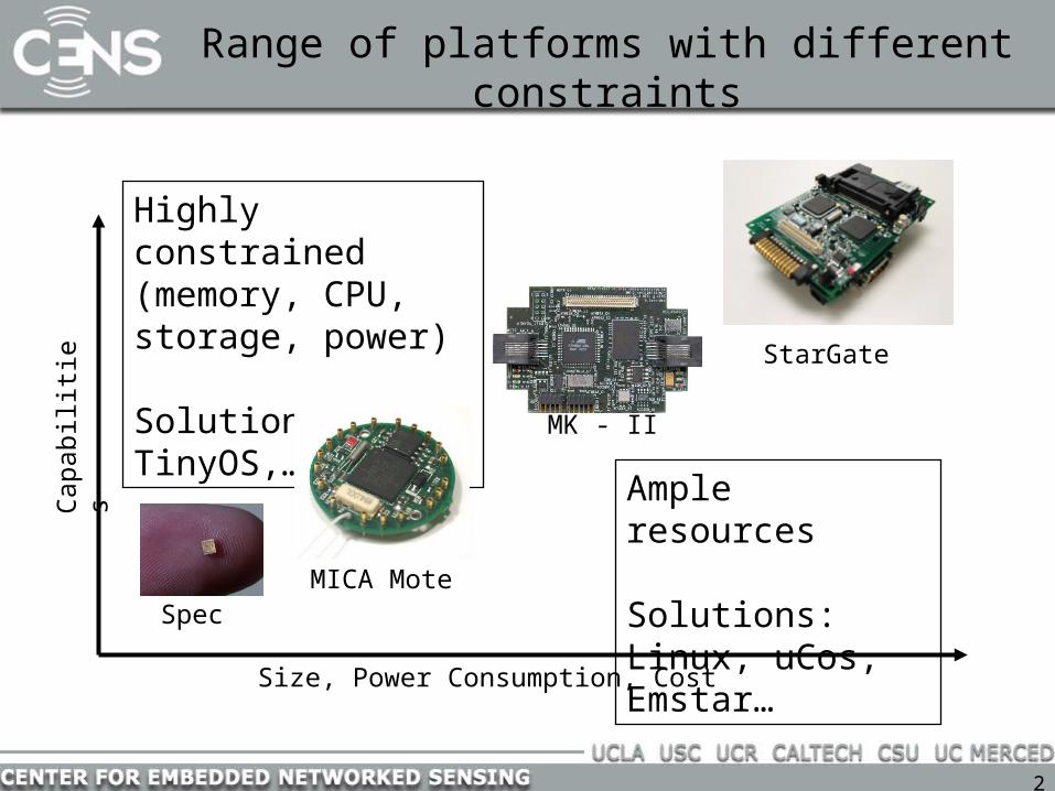
Range of platforms with different constraintsC
apabili
tie
s
Size, Power Consumption, Cost
MICA Mote
MK - II
StarGate
Spec
Ample resources
Solutions: Linux, uCos, Emstar…
Highly constrained (memory, CPU, storage, power)
Solutions: TinyOS,…

3
Why do we use utterly constrained platforms?
• No wires = batteries and radios
• Resources drain batteries– Radio, Flash, ADC, RAM, MCU, etc.
• Deployments are often remote– Don’t always have summer interns to change batteries
• Constrained platforms are smaller• Constrained platforms are cheaper

4
Technology for low-power, cheap nodes
• CMOS miniaturization– 1 M trans/$ tiny (~mm2), inexpensive processing and storage– 1-10 mW active, 1 W passive (at 1% use 100 W average)
• Micro-sensors (MEMS, Materials, Circuits)– acceleration, vibration, gyroscope, tilt, magnetic, heat, motion,
pressure, temp, light, moisture, humidity, barometric– chemical (CO, CO2, radon), biological, micro-radar, ...– actuators too (mirrors, motors, smart surfaces, micro-robots)
• Communication– short range, low bit-rate, CMOS radios (1-10 mW)
• Power– batteries remain primary storage (1,000 mW/mm3), fuel cells 10x– solar (10 mW/cm2, 0.1 mW indoors)
• 1 cm3 battery 1 year at 10 msgs/sec

5
Characteristics of Network Sensors
• Small physical size and low power consumption
• Concurrency-intensive operation– multiple flows, not wait-command-respond=> never poll, never block
• Limited Physical Parallelism and Controller Hierarchy
– primitive direct-to-device interface– Asynchronous and synchronous devices=> interleaving flows, events, energy
management• Diversity in Design and Usage
– application specific, not general purpose– huge device variation=> efficient modularity=> migration across HW/SW boundary
• Robust Operation– numerous, unattended, critical=> narrow interfaces
sensorsactuators
network
storage

6
What is a mote?
• Jason Hill’s Master’s Thesis (UCB)• PhD Dissertation was supposed to be a prototype for a smart-
dust system on a chip– Small physical size: 1 mm3
– Low Power Consumption: < 50 mW
7
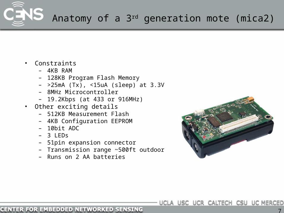
Anatomy of a 3rd generation mote (mica2)
• Constraints– 4KB RAM– 128KB Program Flash Memory– >25mA (Tx), <15uA (sleep) at 3.3V– 8MHz Microcontroller– 19.2Kbps (at 433 or 916MHz)
• Other exciting details– 512KB Measurement Flash– 4KB Configuration EEPROM– 10bit ADC– 3 LEDs– 51pin expansion connector– Transmission range ~500ft outdoor– Runs on 2 AA batteries
8
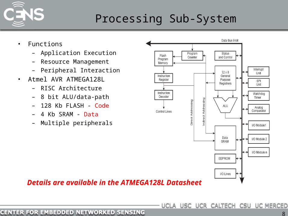
Processing Sub-System
• Functions– Application Execution– Resource Management– Peripheral Interaction
• Atmel AVR ATMEGA128L– RISC Architecture– 8 bit ALU/data-path– 128 Kb FLASH - Code– 4 Kb SRAM - Data– Multiple peripherals
Details are available in the ATMEGA128L Datasheet

9
Sensing Sub-System
• Functions– Sampling physical
signals/phenomena• Different types of sensors
– Photo-sensor– Acoustic Microphone– Magnetometer– Accelerometer
• Sensor Processor Interface– 51 Pin Connector– ON-OFF switches for individual
sensors– Multiple data channels
Sensors consume powerTurn them off after sampling !
Useful Link/Resources• http://www.tinyos.net/ Look under Hardware Designs tab• Crossbow website http://www.xbow.com

10
Mica Weather Board – Weather monitoring applications
• Total Solar Radiation• Photosynthetically Active Radiation
– Resolution: 0.3A/W• Relative Humidity
– Accuracy: ±2%• Barometric Pressure
– Accuracy: ±1.5mbar• Temperature
– Accuracy: ±0.01oC• Acceleration
– 2 axis– Resolution: ±2mg
• Designed by UCB w/ Crossbow and UCLA
Revision 1.5
Revision 1.0

11
Communication Sub-System
• Functions– Transmit – Receive data packets
wirelessly– Co-ordinate/Network with other
nodes• Implementation
– Radio• Modulation – Demodulation• Two types of radios: RFM, ChipCon
CC1000• RFM: Mica & predecessors• CC1000: Mica2 onwards
– AVR• Protocol Processing

12
Wireless Comm. Basics
• RFM Radio– Simple radio, only modulates-demodulates bits• CC1000 Radio– Performs Manchester coding-decoding and synchronization also

13
AVR Peripherals
• UART– Serial communication with the PC
• SPI – Serial Peripheral Interface– Synchronous serial communication– Interface to Radio in the Mote
• ADC– Analog – Digital Converter– Digitizing sensor readings
• I/O Ports– General Purpose Input Output pins (GPIO)– Used to light up LEDs in Mote

14
Radio Power Management
• Radio has very high power consumption– Tx power is range dependant - 49.5 mW (0 dBm)– Rx power is also very high - 28.8 mW– Power-down sleep mode - 0.6 uW– Above data for CC1000, 868 MHz (Check out CC1000 data-sheets for more
numbers)
• Radio power management critical– Idle state channel monitoring power = Rx Power– Put radio to sleep when not in use– But then, how do we know when somebody is trying to contact us ?

15
AVR Power Management
• Low Power operation – 15 mW @ 4 MHz• Multiple Sleep Modes
– Sleep Modes: Shutdown unused components– Idle Mode – 6 mW
• CPU OFF, all peripherals ON• CPU “woken up” by interrupts
– Power Down Mode – 75 uW• CPU and most peripherals OFF• External Interrupts, 2 Wire Interface, Watchdog ON
– Power Save Mode – 120 uW• Similar to Power Down• Timer0 continues to run “asynchronously”

16
Typical sensor network operation
• Sensing Subsystem– Keep the very low power sensors on all the time on each node in the network
• Processing subsystem– Low-power sensors interrupt (trigger) processor when “events” are identified OR– Processor wakes up periodically on clock interrupt, takes a sample from sensor,
processes it, and goes back to sleep.• Radio subsystem
– Processor wakes up radio when event requires collaborative processing or multi-hop routing.
• Tiered architectures of above subsystems can be envisaged in other platforms

17
Traditional Systems
• Well established layers of abstractions
• Strict boundaries
• Ample resources
• Independent apps at endpoints communicate pt-pt through routers
• Well attended
User
System
Physical Layer
Data Link
Network
Transport
Network Stack
Threads
Address Space
Drivers
Files
Application
Application
Routers

18
by comparison ...
• Highly Constrained resources– processing, storage, bandwidth, power
• Applications spread over many small nodes– self-organizing Collectives – highly integrated with changing environment and network– communication is fundamental
• Concurrency intensive in bursts– streams of sensor data and network traffic
• Robust– inaccessible, critical operation

19
So, how do we write programs for motes?
• Write C-style programs using a language for embedded software development (e.g., nesc)
• Use a cross-compiler to build a binary image for a mote MCU (e.g., avr-gcc).
• Use a programmer (e.g., uisp) to load the binary onto a mote
• Event driven execution:– Messages received over radio, discrete event sensors generate
interrupts when they detect things, timers go off.
– We write handlers (functions) that are called in response to various events.
– We write tasks to do background processing

20
What are TinyOS and nesC?
• TinyOS is a collection of software modules that can be glued together to build applications. Examples:
– GenericComm: send and receive radio packets– TimerC: start timers and get notified when they expire– ADC: sample light and temperature data, among others– UART: communicate over the serial interface– LedsC: make pretty lights blink
• TinyOS is also a FIFO scheduler:– Interrupts are handled immediately– Background tasks are scheduled (put on a queue are are executed when
there’s nothing more important to do)
• NesC is the language in which TinyOS modules are written– To define modules and the interfaces that connect them– Can create configurations, which are hierarchies of glued together modules

21
TinyOS Goals (claims)
• Flexibility– new sensor network nodes keep emerging
• Telos, iMote, mica2, mica2Dot, etc.
– Flexible hardware/software interface• Future designs may require different HW/software interfaces and may move service
(MAC, e.g.) into hardware or software
• Modularity– Component model
• Sensor Network Challenges– Address the specific and unusual challenges of sensor networks:
• limited resources, concurrency- intensive operation, a need for robustness, and application-specific requirements.
22
Each mote runs a single application
• Properties– All memory resources are known statically– Rather than employing a general-purpose OS, applications are built from a suite of
reusable system components coupled with application-specific code – The hardware/software boundary varies depending on the application and hardware
platform; it is important to design software for flexible decomposition• Challenges:
– Driven by interaction with the environment (interrupts)– Limited resources (motes)– Reliability– Soft real-time requirements (radio management and sensor polling)– Lacking common service
• Time synchronization

23
TinyOS
● application = scheduler + graph of components● event-driven architecture● single shared stack● NO kernel, process/memory management, virtual memory

24
Application = Graph of Components
RFM
Radio byte
Radio Packet
UART
Serial Packet
ADC
Temp photo
Active Messages
clocksbit
by
tep
ac
ke
t
Route map router sensor appln
ap
pli
ca
tio
n
HW
SW

25
The nesC programming language: moving away from perl
• NesC started with a perl script– Pretended to be a lexer and parser– Offered no compile-time support for error detection– Component model wasn’t there yet
• Now it is a systems programming language for motes• Interrupt-driven programming model
– integrates reactivity to the environment, concurrency, and communication• Provides whole-program optimizations and compile-time data race detection
(does it work?) – Does it simplify application development?– reduce code size?– eliminate many sources of potential bugs?

26
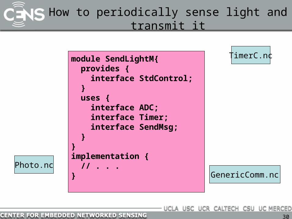
How to periodically sense light and transmit it
Photo.nc
TimerC.nc
GenericComm.nc
I know how to return a light value
I know how to tell someone
when some time has gone by
And I can transmit
messages over a radio!

27
How to periodically sense light and transmit it
Photo.nc
TimerC.nc
GenericComm.nc
I know how to return a light value
I know how to tell someone
when some time has gone by
And I can transmit
messages over a radio! SendLightM.nc
I’m the glue that ties
these modules together

28
How to periodically sense light and transmit it
Photo.nc
TimerC.nc
GenericComm.nc
SendLightM.nc
I am a user of the services these other
modules provide

29
How to periodically sense light and transmit it
Photo.nc
TimerC.nc
GenericComm.nc
SendLightM.nc
Specifically, I use the interfaces that
these modules provide
ADC
Timer
SendMsg
30
How to periodically sense light and transmit it
Photo.nc
TimerC.nc
GenericComm.nc
module SendLightM{ provides { interface StdControl; } uses { interface ADC; interface Timer; interface SendMsg; }}implementation { // . . . }

31
Modules
• A module has:– Frame (internal state)– Tasks (computation)– Interface (events, commands)
• Frame :– one per component– statically allocated– fixed size
• Keyword “includes” goes before module declaration
– Semantic equivalent of #include, with caveats: No cpp directives allowed
– Practical hack: put #include in implementation block
• Commands and events are function calls
• Application: linking/glueing interfaces (events, commands)
includes Foo;module SendLightM{ provides { interface StdControl; } uses { interface ADC; interface Timer; interface SendMsg; }}implementation {#include “FooConstants.h” int x; // a frame variable
task void work(){ // do something }
command result_t StdControl.start(){ call Timer.start(TIMER_REPEAT, 1000); return SUCCESS; } event result_t Timer.fired(){ post work(); }}

32
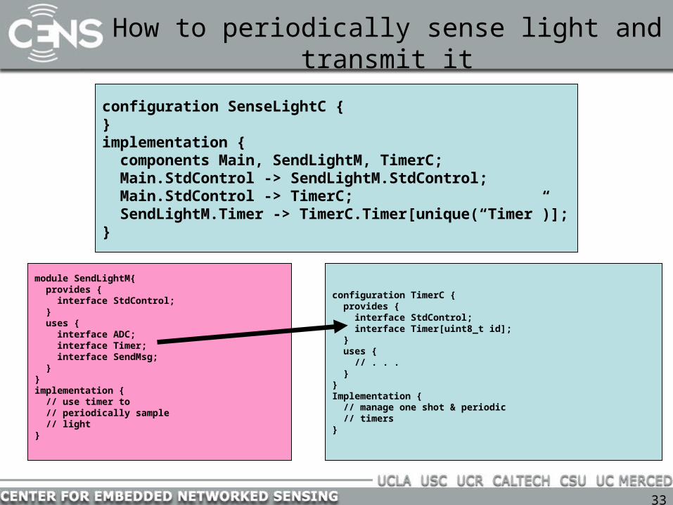
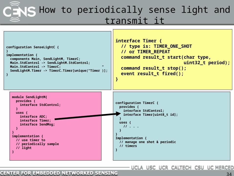
How to periodically sense light and transmit it
configuration TimerC { provides { interface StdControl; interface Timer[uint8_t id]; } uses { // . . . }}Implementation { // manage one shot & periodic // timers}
module SendLightM{ provides { interface StdControl; } uses { interface ADC; interface Timer; interface SendMsg; }}implementation { // use timer to // periodically sample // light }
33
How to periodically sense light and transmit it
configuration TimerC { provides { interface StdControl; interface Timer[uint8_t id]; } uses { // . . . }}Implementation { // manage one shot & periodic // timers}
module SendLightM{ provides { interface StdControl; } uses { interface ADC; interface Timer; interface SendMsg; }}implementation { // use timer to // periodically sample // light }
configuration SenseLightC {}implementation { components Main, SendLightM, TimerC; Main.StdControl -> SendLightM.StdControl; Main.StdControl -> TimerC; SendLightM.Timer -> TimerC.Timer[unique(“Timer”)];}
34
How to periodically sense light and transmit it
configuration TimerC { provides { interface StdControl; interface Timer[uint8_t id]; } uses { // . . . }}Implementation { // manage one shot & periodic // timers}
module SendLightM{ provides { interface StdControl; } uses { interface ADC; interface Timer; interface SendMsg; }}implementation { // use timer to // periodically sample // light }
configuration SenseLightC {}implementation { components Main, SendLightM, TimerC; Main.StdControl -> SendLightM.StdControl; Main.StdControl -> TimerC; SendLightM.Timer -> TimerC.Timer[unique(“Timer”)];}
interface Timer { // type is: TIMER_ONE_SHOT // or TIMER_REPEAT command result_t start(char type, uint32_t period); command result_t stop(); event result_t fired();}

35
Parameterized Interfaces
• Can associate a port with an interface, so that a provider can distinguish users• Used because the provider doesn’t know how many users will be connecting to it
configuration SenseLightC {}implementation { components Main, SendLightM, TimerC; Main.StdControl -> SendLightM.StdControl; Main.StdControl -> TimerC; SendLightM.Timer -> TimerC.Timer[unique(“Timer”)];}
configuration TimerC { provides { interface StdControl; interface Timer[uint8_t id]; } uses { // . . . }}Implementation { // manage one shot & periodic // timers}
TimerC can provide up to 256 instances of the Timer interface.
36
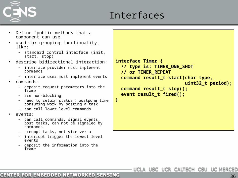
Interfaces
• Define “public methods that a component can use
• used for grouping functionality, like:– standard control interface (init, start,
stop)• describe bidirectional interaction:
– interface provider must implement commands
– interface user must implement events• commands:
– deposit request parameters into the frame
– are non-blocking– need to return status postpone time
consuming work by posting a task– can call lower level commands
• events:– can call commands, signal events, post
tasks, can not be signaled by commands– preempt tasks, not vice-versa– interrupt trigger the lowest level events– deposit the information into the frame
interface Timer { // type is: TIMER_ONE_SHOT // or TIMER_REPEAT command result_t start(char type, uint32_t period); command result_t stop(); event result_t fired();}

37
Interface Examples
interface StdControl { command result_t init (); command result_t start (); command result_t stop ();}
interface Timer { command result_t start (char type, uint32_t interval); command result_t stop (); event result_t fired ();}
interface SendMsg { command result_t send (uint16_t addr, uint8_t len, TOS_MsgPtr p); event result_t sendDone ();}
interface ReceiveMsg { event TOS_MsgPtr receive (TOS_MsgPtr
m);}
StdControl.nc Timer.nc
ReceiveMsg.ncSendMsg.nc

38
How to periodically sense light and transmit it
module SendLightM{ provides { interface StdControl; } uses { interface ADC; interface Timer; interface SendMsg; }}implementation { command result_t StdControl.init() { return SUCCESS; } command result_t StdControl.start(){ call Timer.start(TIMER_REPEAT, 1000); // 1000ms return SUCCESS; } command result_t StdControl.stop(){ call Timer.stop(); return SUCCESS; } event result_t Timer.fired(){ call ADC.getData(); }}
interface Timer { // type is: TIMER_ONE_SHOT // or TIMER_REPEAT command result_t start(char type, uint32_t period); command result_t stop(); event result_t fired();}
interface ADC { async command result_t getData(); async command result_t getContinuousData(); async event result_t dataReady(uint16_t data);}

39
How to periodically sense light and transmit it
module SendLightM{ provides { interface StdControl; } uses { interface ADC; interface Timer; interface SendMsg; }}implementation { command result_t StdControl.init() { return SUCCESS; } command result_t StdControl.start(){ call Timer.start(TIMER_REPEAT, 1000); // 1000ms return SUCCESS; } command result_t StdControl.stop(){ call Timer.stop(); return SUCCESS; } event result_t Timer.fired(){ call ADC.getData(); } async event result_t ADC.dataReady(uint16_t data){ // send a message with the data }}
interface Timer { // type is: TIMER_ONE_SHOT // or TIMER_REPEAT command result_t start(char type, uint32_t period); command result_t stop(); event result_t fired();}
interface ADC { async command result_t getData(); async command result_t getContinuousData(); async event result_t dataReady(uint16_t data);}
Split-phase interface

40
Split-phase Interfaces
• Operation request and completion are separate functions:
• No blocking operations because tasks execute non-preemptively• The usual way to do this is to register a callback by passing a function pointer
interface SendMsg { command result_t send (uint16_t address, uint8_t length, TOS_MsgPtr p); event result_t sendDone (TOS_MsgPtr msg, result_t success);} SendMsg.nc

41
How to periodically sense light and transmit it
• In a configuration, modules and perhaps sub-configurations are connected together by the interfaces they use and provide
• Interfaces have commands and events
module SendLightM{ provides { interface StdControl; } uses { interface ADC; interface Timer; interface SendMsg; }}implementation { command result_t StdControl.init() { return SUCCESS; } command result_t StdControl.start(){ call Timer.start(TIMER_REPEAT, 1000); // 1000ms return SUCCESS; } command result_t StdControl.stop(){ call Timer.stop(); return SUCCESS; } event result_t Timer.fired(){ call ADC.getData(); } async event result_t ADC.dataReady(uint16_t data){ // send a message with the data }}

42
How to periodically sense light and transmit it
• So, what’s this “async” word?
• Some functions, like dataReady are called directly from a hardware interrupt handler.
• Async means that this function might be called straight from the IH.
• Why do we care whether or not a function is called from the IH?
module SendLightM{ provides { interface StdControl; } uses { interface ADC; interface Timer; interface SendMsg; }}implementation { command result_t StdControl.init() { return SUCCESS; } command result_t StdControl.start(){ call Timer.start(TIMER_REPEAT, 1000); // 1000ms return SUCCESS; } command result_t StdControl.stop(){ call Timer.stop(); return SUCCESS; } event result_t Timer.fired(){ call ADC.getData(); }
async event result_t ADC.dataReady(uint16_t data){ // send a message with the data }}
43
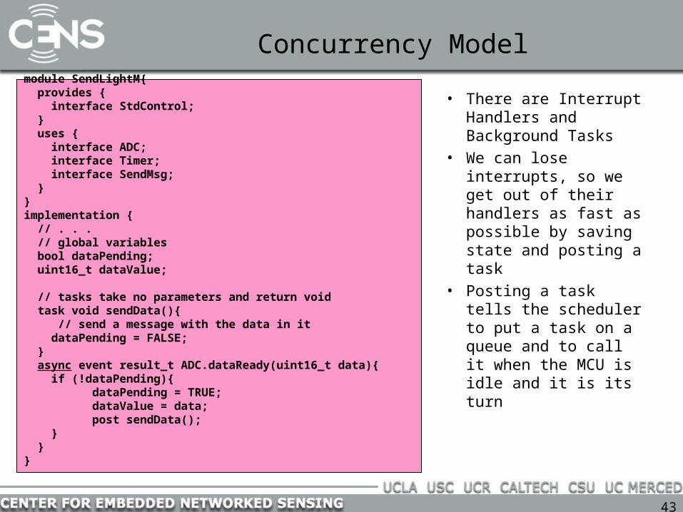
Concurrency Model
• There are Interrupt Handlers and Background Tasks
• We can lose interrupts, so we get out of their handlers as fast as possible by saving state and posting a task
• Posting a task tells the scheduler to put a task on a queue and to call it when the MCU is idle and it is its turn
module SendLightM{ provides { interface StdControl; } uses { interface ADC; interface Timer; interface SendMsg; }}implementation { // . . . // global variables bool dataPending; uint16_t dataValue;
// tasks take no parameters and return void task void sendData(){ // send a message with the data in it dataPending = FALSE; } async event result_t ADC.dataReady(uint16_t data){ if (!dataPending){
dataPending = TRUE; dataValue = data; post sendData(); } }}

44
Concurrency Model
• Since tasks (and even some interrupts) can be interrupted, we sometimes need extra support to prevent race conditions
• Use the keyword atomic to prevent interruption…
• Note, try to avoid calling from within an atomic block
module SendLightM{ // . . .}implementation { // . . . // global variables bool dataPending; uint16_t dataValue;
// tasks take no parameters and return void task void sendData(){ // send a message with the data in it dataPending = FALSE; } async event result_t ADC.dataReady(uint16_t data){ bool doWork = FALSE; atomic { if (!dataPending){ dataPending = TRUE; doWork = TRUE; } } if (doWork) post sendData(); } }}

45
Configurations
• Configurations refer to configurations and modules
• No distinction between an included configuration and an included module
• Configuration can expose an underlying module’s interface
• An application must connect a Main component to other components
• connected elements must be compatible (interface-interface, command-command, event-event)
• 3 wiring statements in nesC:
– endpoint1 = endpoint2
– endpoint1 -> endpoint2
– endpoint1 <- endpoint2
configuration CntToLeds {}implementation { components Main, Counter, IntToLeds, TimerC; Main.StdControl -> IntToLeds.StdControl; Main.StdControl -> Counter.StdControl; Main.StdControl -> TimerC.StdControl; Counter.Timer -> TimerC.Timer[unique("Timer")]; Counter.IntOutput -> IntToLeds.IntOutput;}
configuration TimerC { provides interface Timer[uint8_t id]; provides interface StdControl;}
implementation { components TimerM, ClockC, NoLeds, HPLPowerManagementM;
TimerM.Leds -> NoLeds; TimerM.Clock -> ClockC; TimerM.PowerManagement -> HPLPowerManagementM;
StdControl = TimerM; Timer = TimerM;}

46
Concurrency
• Tasks and interrupts (foreground and background operations)– Tasks cannot preempt other tasks
• Low priority for performing computationally intensive work
– Interrupts can preempt tasks– Interrupts can preempt other interrupts, but not important for this course
• TOSH_INTERRUPT() – interrupt allowed• TOSH_SIGNAL() – interrupt forbidden
• Scheduler– Two level scheduling - interrupts (vector) and tasks (queue)– Queue of tasks
• No associated priorities• FIFO execution
– No local state associated with tasks• Programmer must manage own internal state when tasks need it
– Danger: task queue overflows (because no dynamic memory)
47
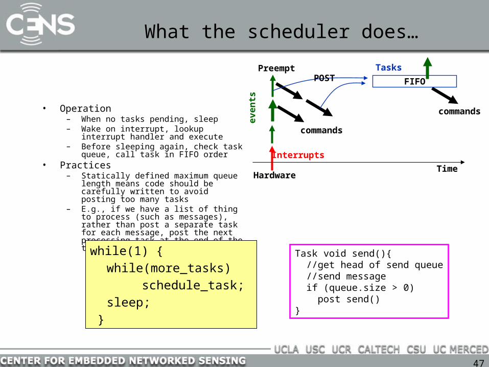
What the scheduler does…
• Operation– When no tasks pending, sleep– Wake on interrupt, lookup interrupt handler
and execute– Before sleeping again, check task queue, call
task in FIFO order• Practices
– Statically defined maximum queue length means code should be carefully written to avoid posting too many tasks
– E.g., if we have a list of thing to process (such as messages), rather than post a separate task for each message, post the next processing task at the end of the task handler
Task void send(){ //get head of send queue //send message if (queue.size > 0) post send()}
Hardware
Interrupts
events
commands
FIFO
TasksPOST
Preempt
Time
commands
while(1) {while(more_tasks)
schedule_task;sleep;
}

48
Posting Tasks
module BlinkM {…}implementation {… task void processing () { if(state) call Leds.redOn(); else call Leds.redOff(); }
event result_t Timer.fired () { state = !state; post processing(); return SUCCESS; }…}
BlinkM.nc

49
Language features for concurrency
• Post – Puts a function on a task queue– Must be void foo(void)– void task do-work() { //do something }– post do-work();
• Atomic– Interrupts can preempt execution– Turn off interrupts with atomic{ }– E.g. to implement a semaphore
• Async– Use async to tell compiler that this code can be called from an
interrupt context – used to detect potential race conditions• Norace
– Use norace to tell compiler it was wrong about a race condition existing (the compiler usually suggests a million possible race conditions)

50
Debugging using print statements
• TinyOS’s printf:– dbg(DBG_USR1, “%s [%d] – link quality is %d\n”,
__FILE__, __LINE__, link_quality);
• DBG_USR1, DBG_USR2, DBG_USR3, and DBG_ERROR are defined for your enjoyment
51
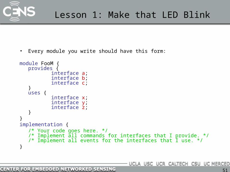
Lesson 1: Make that LED Blink
• Every module you write should have this form:
module FooM { provides {
interface a; interface b; interface c;
} uses {
interface x; interface y; interface z;
} } implementation {
/* Your code goes here. */ /* Implement all commands for interfaces that I provide. */ /* Implement all events for the interfaces that I use. */
}

52
Lesson 1: Make that LED Blink
• Every module you write will need to have an interface called StdControl (standard control). It has three methods:
interface StdControl { /* * Initialize the component and its subcomponents. */ command result_t init(); /* * Start the component and its subcomponents. */ command result_t start(); /* * Stop the component and pertinent subcomponents (not all * subcomponents may be turned off due to wakeup timers, etc.). */ command result_t stop();
}
53
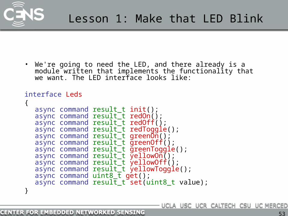
Lesson 1: Make that LED Blink
• We're going to need the LED, and there already is a module written that implements the functionality that we want. The LED interface looks like:
interface Leds {
async command result_t init(); async command result_t redOn(); async command result_t redOff(); async command result_t redToggle(); async command result_t greenOn(); async command result_t greenOff(); async command result_t greenToggle(); async command result_t yellowOn(); async command result_t yellowOff(); async command result_t yellowToggle(); async command uint8_t get(); async command result_t set(uint8_t value);
}

54
Lesson 1: Make that LED Blink
• Let's add these interfaces and the required methods to our module :
module FooM { provides {
interface StdControl; } uses {
interface Leds; }
} implementation {
/* StdControl Interface. */
command result_t StdControl.init() { // Initialize the LEDs.
dbg(DBG_USR3, "%s [%d] - Initialization started.\n", __FILE__, __LINE__);
call Leds.init();
dbg(DBG_USR3, "%s [%d] - Initialization finished.\n", __FILE__, __LINE__);
return SUCCESS; } command result_t StdControl.start() { return SUCCESS; } command result_t StdControl.stop() { return SUCCESS; }
}

55
Lesson 1: Make that LED Blink
• Now we need to be able to generate a periodic event so that we can toggle the LEDs. There is already a component written that does what we want and the interface that exports this functionality is called Timer:
interface Timer {
/* 'type' takes value of either TIMER_REPEAT or TIMER_ONE_SHOT
*/
/* 'interval' is the number of milliseconds until the timer will expire
*/ command result_t start(char type, uint32_t interval);
command result_t stop();
/* EVENT! */ event result_t fired();
}
56
Lesson 1: Make that LED Blink
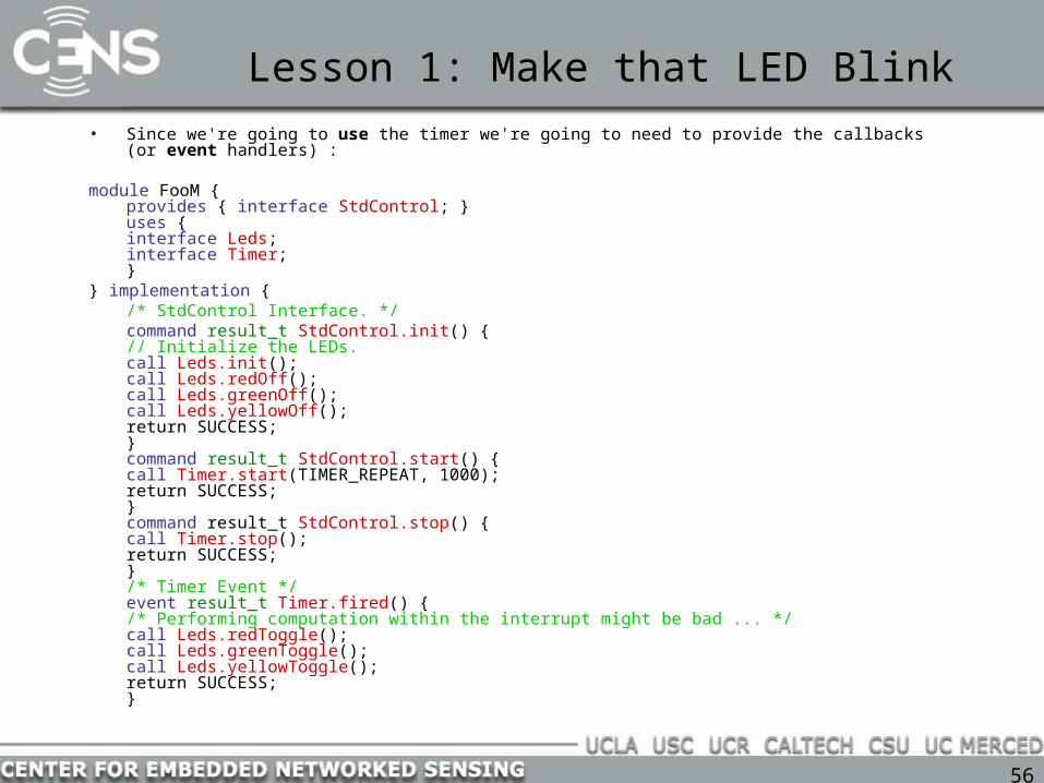
• Since we're going to use the timer we're going to need to provide the callbacks (or event handlers) :
module FooM { provides { interface StdControl; } uses {
interface Leds; interface Timer;
} } implementation {
/* StdControl Interface. */ command result_t StdControl.init() {
// Initialize the LEDs. call Leds.init(); call Leds.redOff(); call Leds.greenOff(); call Leds.yellowOff(); return SUCCESS;
} command result_t StdControl.start() {
call Timer.start(TIMER_REPEAT, 1000); return SUCCESS;
} command result_t StdControl.stop() {
call Timer.stop(); return SUCCESS;
} /* Timer Event */ event result_t Timer.fired() {
/* Performing computation within the interrupt might be bad ... */ call Leds.redToggle(); call Leds.greenToggle(); call Leds.yellowToggle(); return SUCCESS;
}

57
Lesson 1: Make that LED Blink
• Notice that we're doing our "processing" inside the timer event. This amount of processing is negligable, but it is possible to spend too much time inside the interrupt, causing you to miss interrupts, which causes bizaar behavior.
• That's all the code we have to write, but we still need to create a wiring file that explains what other modules will use those interfaces that we provide, and those modules that we will use. Here it is:
configuration Foo { } implementation {
components Main, FooM, LedsC, TimerC; Main.StdControl -> FooM.StdControl; Main.StdControl -> TimerC.StdControl; FooM.Timer -> TimerC.Timer[unique("Timer")]; FooM.Leds -> LedsC.Leds;
}

58
Lesson 2: Using Tasks
• We're going to move our computation into a task that will run in the background :
includes AM; module FooM {
provides { interface StdControl;
} uses { interface Leds; interface Timer;
} }implementation {
/* Tasks must be void! */
task void task_toggleLeds() { call Leds.redToggle();
call Leds.greenToggle();
call Leds.yellowToggle(); }
/* StdControl Interface. */
command result_t StdControl.init(){ // Initialize the LEDs. call Leds.init(); return SUCCESS;
} command result_t StdControl.start(){
call Timer.start(TIMER_REPEAT, 1000);
return SUCCESS; }
command result_t StdControl.stop(){ call Timer.stop(); return SUCCESS;
}
/* Timer Event */ event result_t Timer.fired() {
post task_toggleLeds(); return SUCCESS;
} }

59
Lesson 3: Using the Radio
• So now we want to use the radio to send a simple message, like whether the LEDs are on or off. So we're going to augment our previous code to add a
• tinyos-1.x/tos/interfaces/SendMsg.nc :
interface SendMsg { command result_t send(uint16_t address, uint8_t length, TOS_MsgPtr msg); event result_t sendDone(TOS_MsgPtr m, result_t success);
}
60
Lesson 3: Using the Radio
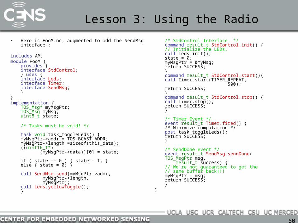
• Here is FooM.nc, augmented to add the SendMsg interface :
includes AM; module FooM {
provides { interface StdControl;
} uses { interface Leds; interface Timer; interface SendMsg;
} } implementation {
TOS_Msg* myMsgPtr; TOS_Msg myMsg; uint8_t state;
/* Tasks must be void! */
task void task_toggleLeds() { myMsgPtr->addr = TOS_BCAST_ADDR;myMsgPtr->length
=sizeof(this_data); ((uint16_t*) (myMsgPtr->data))[0] = state;
if ( state == 0 ) { state = 1; } else { state = 0; }
call SendMsg.send(myMsgPtr->addr, myMsgPtr->length,
myMsgPtr); call Leds.yellowToggle();
}
/* StdControl Interface. */ command result_t StdControl.init() {
// Initialize the LEDs. call Leds.init(); state = 0; myMsgPtr = &myMsg; return SUCCESS;
} command result_t StdControl.start(){
call Timer.start(TIMER_REPEAT, 500);
return SUCCESS; } command result_t StdControl.stop() {
call Timer.stop(); return SUCCESS;
}
/* Timer Event */ event result_t Timer.fired() {
/* Minimize computation */ post task_toggleLeds(); return SUCCESS;
}
/* SendDone event */ event result_t SendMsg.sendDone(
TOS_MsgPtr msg, result_t success) {
// We're not guaranteed to get the
// same buffer back!!! myMsgPtr = msg; return SUCCESS;
} }

61
Lesson 3: Using the Radio
• Here’s the new configuration:
configuration Foo { } implementation {
components Main, FooM, LedsC, TimerC, GenericComm; Main.StdControl -> FooM.StdControl; Main.StdControl -> TimerC.StdControl; Main.StdControl -> GenericComm; FooM.Timer -> TimerC.Timer[unique("Timer")]; FooM.Leds -> LedsC.Leds; FooM.SendMsg -> GenericComm.SendMsg[5];
}

62
Lesson 4: Adding Receive
• GenericComm has more than just a send interface. It also has a receive interface that looks like this:
• tinyos-1.x/tos/interfaces/ReceiveMsg.nc :
interface ReceiveMsg { // Return a pointer to an empty TOS_Msg. event TOS_MsgPtr receive(TOS_MsgPtr m);
}

63
Lesson 4: Adding Receive
• So let's add the event handler. First we'll augment our interfaces, then we'll add in the handler, then we'll add the wiring :
includes AM; module FooM {
provides { interface StdControl;
} uses { interface Leds; interface Timer; interface SendMsg; interface ReceiveMsg;
} } implementation {
// ...
/* ReceiveMsg Event handlers */ event TOS_MsgPtr ReceiveMsg.receive(TOS_MsgPtr m) {
dbg(DBG_USR3, "%s [%d] - Received a message data == %d.\n", __FILE__, __LINE__, ((uint16_t*)(m->data))[0]); call Leds.redToggle(); return m;
} }
64
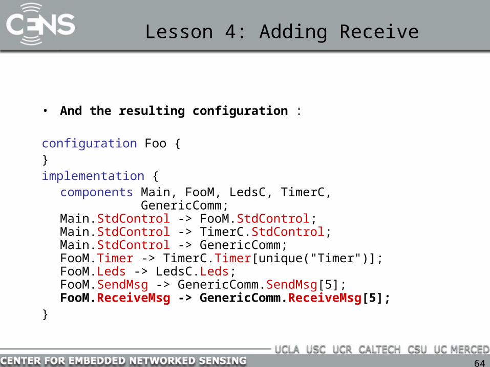
Lesson 4: Adding Receive
• And the resulting configuration :
configuration Foo { } implementation {
components Main, FooM, LedsC, TimerC, GenericComm; Main.StdControl -> FooM.StdControl; Main.StdControl -> TimerC.StdControl; Main.StdControl -> GenericComm; FooM.Timer -> TimerC.Timer[unique("Timer")]; FooM.Leds -> LedsC.Leds; FooM.SendMsg -> GenericComm.SendMsg[5]; FooM.ReceiveMsg -> GenericComm.ReceiveMsg[5];
}
65
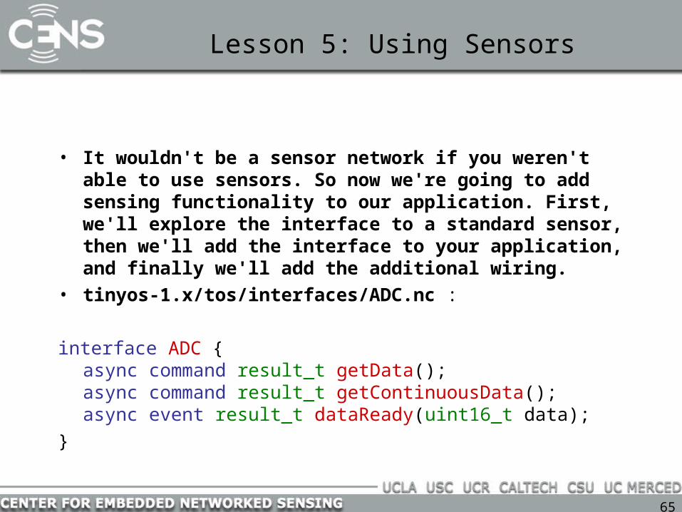
Lesson 5: Using Sensors
• It wouldn't be a sensor network if you weren't able to use sensors. So now we're going to add sensing functionality to our application. First, we'll explore the interface to a standard sensor, then we'll add the interface to your application, and finally we'll add the additional wiring.
• tinyos-1.x/tos/interfaces/ADC.nc :
interface ADC { async command result_t getData(); async command result_t getContinuousData(); async event result_t dataReady(uint16_t data);
}

66
Lesson 5: Using Sensors
includes AM; module FooM {
provides { interface StdControl;
} uses {
interface Leds; interface Timer; interface SendMsg; interface ReceiveMsg; interface ADC;
} } implementation {
// . . .
/* Tasks must be void! */ task void task_toggleLeds() {
call ADC.getData(); call Leds.yellowToggle();
}
// . . ./* Timer Event */ event result_t Timer.fired() {
/* Minimize computation */ post task_toggleLeds(); return SUCCESS;
}
// . . .
/* ADC Data ready event */
async event result_t ADC.dataReady(uint16_t this_data) {
dbg(DBG_USR3, "%s [%d] – DataReady == %d.\n",
__FILE__, __LINE__, this_data);
call Leds.greenToggle(); myMsgPtr->addr = TOS_BCAST_ADDR; myMsgPtr->length =
sizeof(this_data); ((uint16_t*)(myMsgPtr->data))[0]
= this_data; call SendMsg.send(myMsgPtr->addr,
myMsgPtr->length,
myMsgPtr); return SUCCESS;
} }

67
Lesson 5: Using Sensors
• And the resulting configuration :
configuration Foo { } implementation {
components Main, FooM, LedsC, TimerC, GenericComm, Photo; Main.StdControl -> FooM.StdControl; Main.StdControl -> TimerC.StdControl; Main.StdControl -> GenericComm; FooM.Timer -> TimerC.Timer[unique("Timer")]; FooM.Leds -> LedsC.Leds; FooM.SendMsg -> GenericComm.SendMsg[5]; FooM.ReceiveMsg -> GenericComm.ReceiveMsg[5];FooM.ADC -> Photo;
}
68
Lesson 6: Assigning Node IDs
• Assigning a unique identifier to a sensor node is very useful. TinyOS and it's build system already support unique IDs through a special symbol called TOS_LOCAL_ADDRESS.
• We're going to change our application so that in addition to sending a packet containing photo-sensor data, it will include it's own ID so that someone receiving the packet knows where it came from. This won't require any new modules or wiring (Foo.nc will remain the same), only a few lines of code. :

69
Putting it all together
includes AM; module FooM {
provides { interface StdControl;
} uses {
interface Leds; interface Timer; interface SendMsg; interface ReceiveMsg; interface ADC;
} } implementation {
/* Tasks must be void! */
TOS_Msg* myMsgPtr; TOS_Msg myMsg; uint8_t state;
/* Tasks must be void! */
task void task_toggleLeds() { dbg(DBG_USR3, "%s [%d] - Call Get Data.\n", __FILE__, __LINE__); call ADC.getData(); dbg(DBG_USR3, "%s [%d] - Toggle Yellow.\n", __FILE__, __LINE__); call Leds.yellowToggle();
}

70
Putting it all together
/* StdControl Interface. */
command result_t StdControl.init() { // Initialize the LEDs. dbg(DBG_USR3, "%s [%d] - Initialization started.\n",
__FILE__, __LINE__); call Leds.init(); state = 0; myMsgPtr = &myMsg; dbg(DBG_USR3, "%s [%d] - Initialization finished.\n",
__FILE__, __LINE__); return SUCCESS;
} command result_t StdControl.start() {
dbg(DBG_USR3, "%s [%d] - Starting timer.\n", __FILE__, __LINE__);
call Timer.start(TIMER_REPEAT, 500); return SUCCESS;
} command result_t StdControl.stop() {
dbg(DBG_USR3, "%s [%d] - Stopping timer.\n", __FILE__, __LINE__);
call Timer.stop(); return SUCCESS;
}

71
Putting it all together
/* Timer Event */
event result_t Timer.fired() { dbg(DBG_USR3, "%s [%d] - Timer fired.\n", __FILE__, __LINE__); /* Minimize computation */ post task_toggleLeds(); return SUCCESS;
}
/* SendDone event */
event result_t SendMsg.sendDone(TOS_MsgPtr msg, result_t success) { dbg(DBG_USR3, "%s [%d] - Send complete.\n", __FILE__, __LINE__); // We're not guaranteed to get the same buffer back!!! myMsgPtr = msg; return SUCCESS;
}
/* ReceiveMsg Event handlers */
event TOS_MsgPtr ReceiveMsg.receive(TOS_MsgPtr m) { dbg(DBG_USR3, "%s [%d] - Received a message data == %d.\n", __FILE__, __LINE__, ((uint16_t*)(m->data))[0]); call Leds.redToggle(); return m;
}

72
Putting it all together
/* ADC Data ready event */
async event result_t ADC.dataReady(uint16_t this_data) { dbg(DBG_USR3,
"%s [%d] - Data Ready == %d.\n", __FILE__, __LINE__, this_data); call Leds.greenToggle(); myMsgPtr->addr = TOS_BCAST_ADDR; myMsgPtr->length = sizeof(this_data); ((uint16_t*)(myMsgPtr->data))[0] = TOS_LOCAL_ADDRESS; ((uint16_t*)(myMsgPtr->data))[1] = this_data; call SendMsg.send(myMsgPtr->addr, myMsgPtr->length,
myMsgPtr); return SUCCESS; }
}

73
Programming Environment
• OS: cygwin/Win2000 or gcc/Linux
• Software: atmel tools, java, perl
mote
programming board
mote-PC comms Code
download

74
nesC details
• naming conventions:– nesC files suffix: .nc
– C stands for Configuration (Clock, ClockC)
– M stands for Module (Timer, TimerC, TimerM)
?
Clock.nc
?
ClockC.nc
configuration ClockC { ...}
implementation {…}
ClockC.nc
interface Clock { ...}
Clock.nc
?
Timer.nc
interface Timer { ...}
Timer.nc
?
TimerC.nc
?
TimerM.nc
configuration TimerC { ...}
implementation {…}
TimerC.nc
module TimerM { ...}
implementation {…}
TimerM.nc
● clarifications:– “C” distinguishes between
an interface and the component that provides it
– “M” when a single component has both: a configuration, a module

75
Compiling an application
• Avr cross-compilation– Specify platform, programming interface, mote ID– To make and install a binary with ID of 3:
• make mica2 install.3
– To install a preexisting binary with ID of 12:• make mica2 reinstall.12
• Pc native compilation– Create a binary that runs on your pc for debugging and simulation– Make pc, make emstar

76
Directory structure
• tos-contrib– make-contrib – where all contributed projects go– project-name – a particular project that has been contributed
• apps – the applications written for this project– Makefile
» Directives for all application in this project– Makerules– Foo-App
» Makefile – define TOSH_DATA_LENGTH, sensorboards, etc» Foo-App.nc – top-level configuration for the application» Foo-AppM.nc - non-reusable application-specific code
• lib - Configurations and modules defined for the project• interfaces - interfaces defined to be used with the modules and
configurations in lib
• tinyos-1.x has same structure (apps, lib, interfaces) as tos-contrib
77
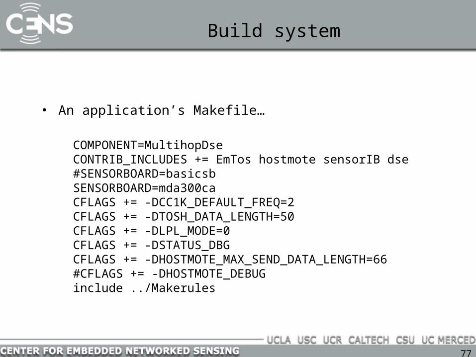
Build system
• An application’s Makefile…
COMPONENT=MultihopDseCONTRIB_INCLUDES += EmTos hostmote sensorIB dse#SENSORBOARD=basicsbSENSORBOARD=mda300caCFLAGS += -DCC1K_DEFAULT_FREQ=2CFLAGS += -DTOSH_DATA_LENGTH=50CFLAGS += -DLPL_MODE=0CFLAGS += -DSTATUS_DBGCFLAGS += -DHOSTMOTE_MAX_SEND_DATA_LENGTH=66#CFLAGS += -DHOSTMOTE_DEBUGinclude ../Makerules

78
Build system integration with Emstar
• Tricky to get TinyOS and Emstar to play nice
• Read: http://cvs.cens.ucla.edu/emstar/install.html
• Basically, a few symbolic links need to be established
• To build in emstar:– $EMSTAR_ROOT points to your emstar distribution– $TOSDIR points to your TinyOS distribution– in Make.conf set BUILD_EMTOS to 1– make [ARCH=mica2]
79
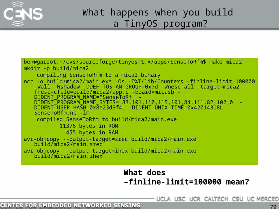
What happens when you build a TinyOS program?
ben@garrot:~/cvs/sourceforge/tinyos-1.x/apps/SenseToRfm$ make mica2mkdir -p build/mica2 compiling SenseToRfm to a mica2 binaryncc -o build/mica2/main.exe -Os -I%T/lib/Counters -finline-limit=100000
-Wall -Wshadow -DDEF_TOS_AM_GROUP=0x7d -Wnesc-all -target=mica2 -fnesc-cfile=build/mica2/app.c -board=micasb -DIDENT_PROGRAM_NAME="SenseToRf" -DIDENT_PROGRAM_NAME_BYTES="83,101,110,115,101,84,111,82,102,0" -DIDENT_USER_HASH=0x8e23d3f4L -DIDENT_UNIX_TIME=0x42014318L SenseToRfm.nc -lm
compiled SenseToRfm to build/mica2/main.exe 11376 bytes in ROM 455 bytes in RAMavr-objcopy --output-target=srec build/mica2/main.exe
build/mica2/main.srecavr-objcopy --output-target=ihex build/mica2/main.exe
build/mica2/main.ihex
What does –finline-limit=100000 mean?

80
The main() scheduler loop(tos/system/RealMain.nc)
int main() __attribute__ ((C, spontaneous)) { call hardwareInit(); call Pot.init(10); TOSH_sched_init(); call StdControl.init(); call StdControl.start(); __nesc_enable_interrupt();
while(1) { TOSH_run_task(); } }}
How are tasks handled? How are interrupts handled?

81
Under the hood: app.c
SenseToInt.nc: event result_t Timer.fired() { call ADC.getData(); return SUCCESS; }
# 75 "/home/ben/cvs/sourceforge/tinyos-1.x/tos/lib/Counters/SenseToInt.nc"
result_t SenseToInt$Timer$fired(void)#line 75{ SenseToInt$ADC$getData(); return SUCCESS;}
nesC compilation

82
Mapping callers to callees
• apps/SenseToRfm/SenseToRfm.nc:components Main, SenseToInt, IntToRfm, TimerC, DemoSensorC as Sensor;SenseToInt.ADC -> Sensor;
• tos/sensorboards/micasb/DemoSensorC.nc:components Photo as Sensor;ADC = Sensor;
• tos/sensorboards/micasb/Photo.nc:provides interface ADC as PhotoADC;components PhotoTemp;PhotoADC = PhotoTemp.ExternalPhotoADC;
• tos/sensorboards/micasb/PhotoTemp.nc:components PhotoTempM, ADCC, TimerC;ExternalPhotoADC = PhotoTempM.ExternalPhotoADC;PhotoTempM.InternalPhotoADC -> ADCC.ADC[TOS_ADC_PHOTO_PORT];
app.c:# 52 "/home/ben/cvs/sourceforge/tinyos-
1.x/tos/interfaces/ADC.nc“inline static result_t
SenseToInt$ADC$getData(void){#line 52 unsigned char result;#line 52#line 52 result =
PhotoTempM$ExternalPhotoADC$getData();
#line 52#line 52 return result;#line 52}
How does nesC know we wanted to call PhotoTempM.nc’s getData()?

83
Posting a task
async command result_t ExternalPhotoADC.getData(){
atomic { photoSensor =
stateReadOnce; }; post getSample(); return SUCCESS; }
static inline# 329
"/home/ben/cvs/sourceforge/tinyos-1.x/tos/sensorboards/micasb/PhotoTempM.nc"
result_t PhotoTempM$ExternalPhotoADC$getData(void)
#line 329{ { __nesc_atomic_t __nesc_atomic =
__nesc_atomic_start();#line 330 { PhotoTempM$photoSensor =
PhotoTempM$stateReadOnce; }#line 332 __nesc_atomic_end(__nesc_atomic); }#line 332 ; TOS_post(PhotoTempM$getSample); return SUCCESS;}
• No priorities• No parameters

84
Adding a task to the scheduler(./tos/system/sched.c)
bool TOS_post(void (*tp)(void)){ __nesc_atomic_t fInterruptFlags; uint8_t tmp;
fInterruptFlags = __nesc_atomic_start();
tmp = TOSH_sched_free;
if (TOSH_queue[tmp].tp == (void *)0) { TOSH_sched_free = (tmp + 1) & TOSH_TASK_BITMASK; TOSH_queue[tmp].tp = tp; __nesc_atomic_end(fInterruptFlags); return TRUE; } else { __nesc_atomic_end(fInterruptFlags); return FALSE; }}
Where are the parameters to the task being posted?

85
The main() scheduler loop(tos/system/RealMain.nc)
int main() __attribute__ ((C, spontaneous)) { call hardwareInit(); call Pot.init(10); TOSH_sched_init(); call StdControl.init(); call StdControl.start(); __nesc_enable_interrupt();
while(1) { TOSH_run_task(); } }}
# 54 "/home/ben/cvs/sourceforge/tinyos-1.x/tos/system/RealMain.nc"
int main(void)#line 54{ RealMain$hardwareInit(); RealMain$Pot$init(10); TOSH_sched_init();
RealMain$StdControl$init(); RealMain$StdControl$start(); __nesc_enable_interrupt();
while (1) { TOSH_run_task(); }}
86
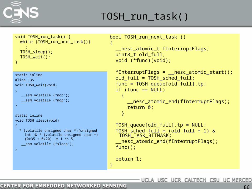
TOSH_run_task()
void TOSH_run_task() { while (TOSH_run_next_task()) ; TOSH_sleep(); TOSH_wait();}
bool TOSH_run_next_task (){ __nesc_atomic_t fInterruptFlags; uint8_t old_full; void (*func)(void); fInterruptFlags = __nesc_atomic_start(); old_full = TOSH_sched_full; func = TOSH_queue[old_full].tp; if (func == NULL) { __nesc_atomic_end(fInterruptFlags); return 0; }
TOSH_queue[old_full].tp = NULL; TOSH_sched_full = (old_full + 1) &
TOSH_TASK_BITMASK; __nesc_atomic_end(fInterruptFlags); func();
return 1;}
static inline
#line 135
void TOSH_wait(void)
{
__asm volatile ("nop");
__asm volatile ("nop");
}
static inline
void TOSH_sleep(void)
{
* (volatile unsigned char *)(unsigned int )& * (volatile unsigned char *)(0x35 + 0x20) |= 1 << 5;
__asm volatile ("sleep");
}

87
Atomic operations
void task outputTask() { uint16_t rCopy; atomic { rCopy = reading; } call IntOutput.output(rCopy >> 7); }
void SenseToInt$outputTask(void)#line 80{ uint16_t rCopy;
#line 82 { __nesc_atomic_t __nesc_atomic =
__nesc_atomic_start();#line 82 { rCopy = SenseToInt$reading; }#line 84 __nesc_atomic_end(__nesc_atomic); } SenseToInt$IntOutput$output(rCopy >>
7);}
Why should we use atomic blocks?

88
Atomic operations
typedef uint8_t __nesc_atomic_t;
inline __nesc_atomic_t __nesc_atomic_start(void) __attribute__((spontaneous))
{ __nesc_atomic_t result = inp(SREG); cli(); return result;}
inline void __nesc_atomic_end(__nesc_atomic_t oldSreg) __attribute__((spontaneou
s)){ outp(oldSreg, SREG);}
#line 153__inline __nesc_atomic_t __nesc_atomic_start(void
){ __nesc_atomic_t result = * (volatile unsigned
char *)(unsigned int )& * (volatile unsigned char *)(0x3F + 0x20);
#line 156 __asm volatile ("cli"); return result;}#line 160__inline void __nesc_atomic_end(__nesc_atomic_t
oldSreg){ * (volatile unsigned char *)(unsigned int )& *
(volatile unsigned char *)(0x3F + 0x20) = oldSreg;
}
cli() disables all interrupts by clearing the global interrupt mask. sei() enables.inp() reads a specified 8-bit port. outp() writes.
89
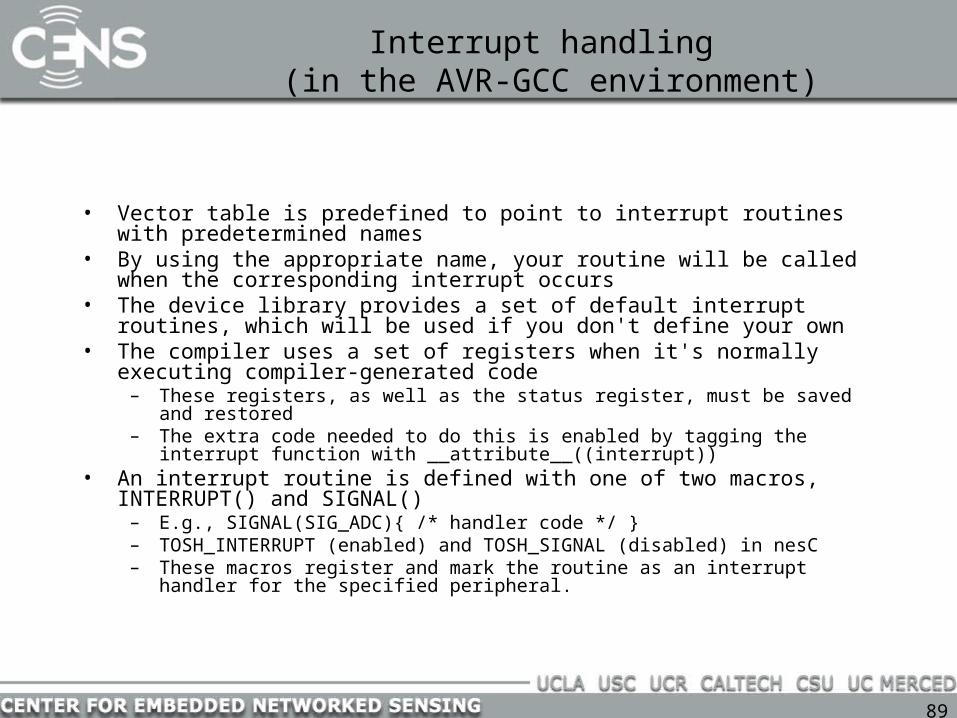
Interrupt handling (in the AVR-GCC environment)
• Vector table is predefined to point to interrupt routines with predetermined names
• By using the appropriate name, your routine will be called when the corresponding interrupt occurs
• The device library provides a set of default interrupt routines, which will be used if you don't define your own
• The compiler uses a set of registers when it's normally executing compiler-generated code
– These registers, as well as the status register, must be saved and restored – The extra code needed to do this is enabled by tagging the interrupt function with
__attribute__((interrupt))• An interrupt routine is defined with one of two macros, INTERRUPT() and
SIGNAL()– E.g., SIGNAL(SIG_ADC){ /* handler code */ }– TOSH_INTERRUPT (enabled) and TOSH_SIGNAL (disabled) in nesC – These macros register and mark the routine as an interrupt handler for the specified
peripheral.

90
Interrupt handlers
TOSH_SIGNAL(SIG_ADC) { uint16_t data = inw(ADCL); data &= 0x3ff; sbi(ADCSR, ADIF); cbi(ADCSR, ADEN); __nesc_enable_interrupt(); signal ADC.dataReady(data); }
#define TOSH_SIGNAL(signame)
void signame() __attribute__ ((signal, spontaneous, C))
# 144 "/home/ben/cvs/sourceforge/tinyos-1.x/tos/platform/mica2/HPLADCM.nc"
void __attribute((signal)) __vector_21(void)
#line 144{ uint16_t data = * (volatile unsigned
int *)(unsigned int )& * (volatile unsigned char *)(0x04 + 0x20);
#line 146 data &= 0x3ff; * (volatile unsigned char *)(unsigned
int )& * (volatile unsigned char *)(0x06 + 0x20) |= 1 << 4;
* (volatile unsigned char *)(unsigned int )& * (volatile unsigned char *)(0x06 + 0x20) &= ~(1 << 7);
__nesc_enable_interrupt(); HPLADCM$ADC$dataReady(data);}
91
Memory management
• Static allocation in TinyOS• No cross-module protection• Scary avr-glib implementation of malloc()
92
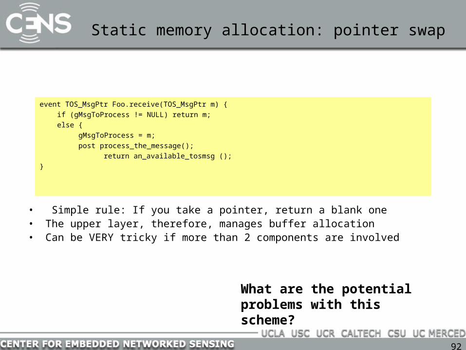
Static memory allocation: pointer swap
event TOS_MsgPtr Foo.receive(TOS_MsgPtr m) {
if (gMsgToProcess != NULL) return m;
else {
gMsgToProcess = m;
post process_the_message();
return an_available_tosmsg ();
}
• Simple rule: If you take a pointer, return a blank one• The upper layer, therefore, manages buffer allocation• Can be VERY tricky if more than 2 components are involved
What are the potential problems with this scheme?

93
Dynamic memory allocation(avr-libc-1.2.1/stdlib/malloc.c)
/* Step 3: If the request could not be satisfied from a freelist entry, * just prepare a new chunk. This means we need to obtain more memory * first. The largest address just not allocated so far is remembered in * the brkval variable. Under Unix, the "break value" was the end of the * data segment as dynamically requested from the operating system. Since * we don't have an operating system, just make sure that we don't collide * with the stack. */
//...
cp = STACK_POINTER() - __malloc_margin; // margin is 32 by defaultavail = cp - __brkval;
What are the potential problems with this scheme?

94
User-implemented dynamic memory pools
uint8_t mem[MemoryPoolM____size];
command void *Memory_p.malloc(uint8_t len){ mem_hdr_t *f = get_first_fit(len); if (f == NULL){ dbg(DBG_ERROR, "%s [%d] - can't allocate %d bytes: out of memory\n", __FILE__,__LINE__, len); return NULL; } allocate(f,len); dbg(DBG_USR1, "%s [%d] memory malloc %p len %d total bytes %d total ptrs %d\n", __FILE__,__LINE__,f->data,len,gAlloc, gPtrs); return f->data; }mem_hdr_t *get_first_fit(uint8_t len){ mem_hdr_t *f = (mem_hdr_t *)mem; while (f != NULL){ dbg(DBG_USR1, "%s [%d] - %p size %d len to fit %d\n", __FILE__,__LINE__,f, get_size(f), len); if (get_size(f) >= len && f->allocated == FALSE){ return f; } f = f->next; } return NULL; }
What are the potential problems with this scheme?

The End