an introduction to screw gas compression · advantages of the screw compressor to the power savings...
TRANSCRIPT

2325 20th Avenue NE, Calgary, AB T2E 8S4 Phone: 403.250.8810 Fax: 403.250.8815
[email protected] www.sageenergy.ca
AN INTRODUCTION TO SCREW GAS COMPRESSION By Trent Bruce
When it comes to selecting a compressor for natural gas compression, rotary screw compressors offer many advantages. This article offers an excellent introduction to rotary screw gas compression. Abstract
Screw compressors have been used on air and various refrigeration and process applications for a great number of years. In recent years the machines have become very popular in the natural gas industry for natural gas compression; specifically, for booster and gas gathering applications. Declining field pressures in the USA and Canada are forcing the industry to look at more flexible gas compression alternatives to the conventional reciprocating compressor.
This paper will discuss specific applications where screw gas compressors are used and the advantages of the rotary screw for natural gas compression to conventional reciprocating machines. We will look at some specific features of the screw compressor, which make it the machine of choice for many gas compression applications requiring high reliability, low maintenance costs and a very wide overall operating range.
We will look at a graphic model of a typical process flow diagram and review the components required to make up a rotary screw gas compressor package. We will also take a detailed look at the internals of the machine to better understand the overall operation, capacity control system, and the associated power savings that go with it when using screw compressors for natural gas compression.
It is extremely important to optimize adiabatic efficiencies in order to provide reduced power costs. On rotary screw gas compressors this is done using a feature called Vi, or internal volume ratio. The Vi can be changed on different machines using a couple of different methods. We will compare both these methods and their associated advantages.
Project economics always play an important role in any equipment selection. With the proper flexibility built into the initial package, rotary screw gas compression units can be used on numerous applications.
In review, this paper will provide a detailed look at screw compressors, where they are applied and exactly how they operate. We will compare the rotary screw gas compressor to other types of machines for similar natural gas compression applications and show the benefits in using this type of machine.
2325 20th Avenue NE, Calgary, AB T2E 8S4 Phone: 403.250.8810 Fax: 403.250.8815
[email protected] www.sageenergy.ca
INTRODUCTION TO SCREW COMPRESSORS FOR NATURAL GAS COMRPESSION
Oil flooded rotary screw compressors have been widely used on various air and refrigeration
applications for over forty years. These machines did not make a significant presence in the natural gas compression industry until the early 1990’s. Until this time, reciprocating compressors had been used almost exclusively for natural gas compression. As gas fields have matured and field pressures have dropped, screw compressors have become a very attractive alternative and supplement to reciprocating gas compressors.
This paper will discuss some of the applications and features of screw compressors, basic operating principles and the advantages of the rotary screw compressor over conventional reciprocating compressors for the natural gas compression industry. We will look at the machine itself, as well as the overall compression system and the components required in a screw gas compressor package. The screw compressors we will focus on are the oil flooded, heavy duty process gas machines rather than the air derivative types. We will provide numerous illustrations to help better understand the screw machine in natural gas compression applications.
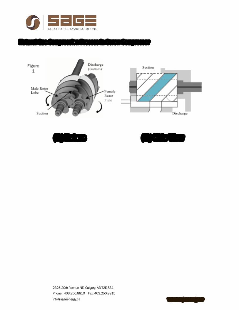
Figure 1 shows the basic geometry of the rotary screw compressor. View (A) is a simple representation of the actual rotors. We have labeled the male rotor lobe and the female rotor flute. As the rotors turn in an outward direction, the male flute will unmesh from the female flute forming an area for the gas to enter. The gas becomes trapped in the machine and compression occurs when the lobes of the rotors begin to mesh together again. The shaded area represents the pocket of gas that occurs within a specific flute. View (B) is a representation of the side view of the machine. The same flute is shaded for comparison. Here we see the suction port in the upper left corner and the discharge port in the lower right corner. The rotors will turn in an outward direction forcing the male and female flutes to unmesh, allowing process gas to enter the top of the machine. The gas will travel around the outside of the rotors until it reaches the bottom where the gas compression actually occurs. Gas will be discharged in the lower right corner of the picture.
2325 20th Avenue NE, Calgary, AB T2E 8S4 Phone: 403.250.8810 Fax: 403.250.8815
[email protected] www.sageenergy.ca
Natural Gas Compression Process in Screw Compressor
(A) Rotors (B) Side View
2325 20th Avenue NE, Calgary, AB T2E 8S4 Phone: 403.250.8810 Fax: 403.250.8815
[email protected] www.sageenergy.ca
APPLICATIONS FOR SCREW GAS COMPRESSORS
The rotary screw compressor is designed for low pressure applications with inlet pressures
ranging from vacuum pressure up to 100 psig and discharge pressures up to 350 psig. These pressure ranges are typical for most process style machines and can vary depending on manufacturer, frame size and operating speed. There are some screw machines available capable of operating at higher pressures by using cast steel casings but these are not yet commonly used in the natural gas compression industry due to capital cost and availability.
Screw compressors are commonly used in a variety of air compression, process gas compression, process refrigeration compression and natural gas compression applications, including individual wellhead boosters, low pressure gathering systems, low stage boosters to existing reciprocating gas compressors, solution gas compression and flare gas compression. They have been used on sweet and sour gas as well as acid gas applications with H2S concentrations of 35% and CO2 concentrations of 65%. Although most natural gas compression applications are based on a specific gravity of 0.57 – 0.65, screw gas compressors can be used on very light gases such as hydrogen and very heavy mole weight gases where specific gravities exceed 2.0.
The most common applications for screw compressors in natural gas service range in horsepower from roughly 90 to 1,500 and are available in both engine and electric drive. Screw compressors were originally developed to operate with electric drive two pole motors at 3,550 rpm. As they have become more popular for natural gas compression, engine drive applications have become much more common. On most of these applications, the screw compressor is operating direct drive at 1800 rpm, or half the rated speed.
2325 20th Avenue NE, Calgary, AB T2E 8S4 Phone: 403.250.8810 Fax: 403.250.8815
[email protected] www.sageenergy.ca
FEATURES OF THE SCREW COMPRESSOR
The rotary screw compressor is a positive displacement machine that operates without the
need for suction or discharge valves. It has the ability to vary suction volume internally while reducing part load power consumption. Screw compressors provide a much wider operating range and lower maintenance costs than conventional reciprocating gas compressors. Screw compressors are also much smaller and create much lower vibration levels than reciprocating compressors. Screw Gas Compressors Offer Reduced Maintenance
The only significant moving parts in a screw gas compressor are the male and female rotors. There are no valves, pistons, rings, or connecting rods that require regular maintenance. With the elimination of the pistons, rings and valves, annual maintenance costs are also reduced on screw gas compressors. It is not uncommon to operate screw compressors for several years without ever performing any significant maintenance repairs. When comparing screw gas compressors and reciprocating gas compressors, it is important to consider maintenance costs into the overall project cost. Screw Compressor Turn Down for Gas Compression Applications
Screw compressors offer turn down capabilities up to 90% of full load with very good part load power requirements. This turn down capability occurs within the machine and is independent of engine speed or bypass. This makes the machine an attractive alternative for gas compression applications where flow rates and operating conditions are not constant. The capacity control can typically be handled manually or automatically within the machine to meet the exact demands of the overall system. Controlling the flow rate of natural gas through the machine significantly reduces the need for an external discharge to suction bypass valve. This bypass system is the most common means of automatic capacity control on reciprocating compressors. Using an external bypass valve or a suction pressure control valve consumes much more power than reducing the flow rate of gas within the compressor. The ability to adjust capacity within the machine is comparable to varying the stroke length and suction volume on a reciprocating machine. However, the screw compressor can vary capacity automatically where the reciprocating machine must have the variable volume pockets adjusted manually. The turn down capability using variable volume pockets is much less than the screw machine as well.
2325 20th Avenue NE, Calgary, AB T2E 8S4 Phone: 403.250.8810 Fax: 403.250.8815
[email protected] www.sageenergy.ca
Screw Compressors Offer High Compression Ratios
Screw compressors can operate from roughly 2 to 20 ratios of compression on a single stage while maintaining high volumetric efficiencies. These efficiencies are achieved by injecting large quantities of lube oil into the machine during the compression process. Oil is typically injected into the compressor at an approximate rate of 10-20 USGPM per 100 HP, which significantly reduces the discharge temperature of the process gas. The oil is discharged with the process gas and will be removed later from the gas stream. The oil also serves as the driving force for the non-driven rotor. Where dry screw compressors rely on timing gears, the oil flooded screw compressor uses a film of lube oil between the drive and non-drive rotors.
Reciprocating compressors can operate at much higher pressures than screw compressors, but are typically limited to roughly 4 ratios of compression per stage. Multi-staging and inter-cooling these compressors is required to prevent poor volumetric efficiencies, rod loading and excessive discharge temperatures. In applications where the system compression ratios exceed four, multi-stage reciprocating machines will offer better adiabatic efficiencies, or power requirements, than the single stage screw compressors. In this case the user must weigh the advantages of the screw compressor to the power savings of the reciprocating compressor.
Screw Compressors Accommodate Wide Operating Ranges
The screw compressor itself can operate over a very wide range with little or no changes required to the machine. This makes it very well suited for natural gas compression applications where flow rates and operating conditions are often changing. Over time, as field conditions change, many reciprocating compressors encounter rod loading or temperature problems and require costly retrofits. This often entails changing cylinders, changing cooler sections and often re-staging the machine. In contrast, screw compressors are designed to operate over the entire range with no changes to the compressor itself. Screw Compressors Enable Smaller Package Sizes
Rotary screw gas compressors provide high capacities with minimal installation space compared to reciprocating compressors. Based on a full speed design of 3,600 rpm, a large screw gas compressor can provide over 50 MMSCFD of gas based on a 100 psig suction pressure. The physical size of the compressor is much smaller than a comparable reciprocating gas compressor.
2325 20th Avenue NE, Calgary, AB T2E 8S4 Phone: 403.250.8810 Fax: 403.250.8815
[email protected] www.sageenergy.ca
Lower Vibration with Screw Gas Compressors
With only two major moving parts operating in a circular motion, screw compressors create much lower vibration levels than reciprocating compressors. Although the slide valve assembly also moves to control capacity, it happens at such a slow rate that we do not consider it a maintenance concern. With lower vibration levels, screw compressors do not require the same type of foundation as the reciprocating compressors, which can result in lower installation costs.
In general, screw compressors for gas compression are considered to provide very high reliability, resulting in lower maintenance costs and reduced down time compared to reciprocating compressors.
2325 20th Avenue NE, Calgary, AB T2E 8S4 Phone: 403.250.8810 Fax: 403.250.8815
[email protected] www.sageenergy.ca
SCREW COMPRESSOR BASIC OPERATING PRINCIPLES
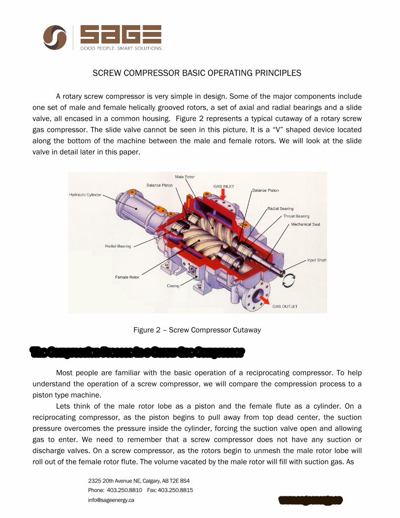
A rotary screw compressor is very simple in design. Some of the major components include
one set of male and female helically grooved rotors, a set of axial and radial bearings and a slide valve, all encased in a common housing. Figure 2 represents a typical cutaway of a rotary screw gas compressor. The slide valve cannot be seen in this picture. It is a “V” shaped device located along the bottom of the machine between the male and female rotors. We will look at the slide valve in detail later in this paper.
Figure 2 – Screw Compressor Cutaway
The Compression Process in a Screw Gas Compressor
Most people are familiar with the basic operation of a reciprocating compressor. To help understand the operation of a screw compressor, we will compare the compression process to a piston type machine.
Lets think of the male rotor lobe as a piston and the female flute as a cylinder. On a reciprocating compressor, as the piston begins to pull away from top dead center, the suction pressure overcomes the pressure inside the cylinder, forcing the suction valve open and allowing gas to enter. We need to remember that a screw compressor does not have any suction or discharge valves. On a screw compressor, as the rotors begin to unmesh the male rotor lobe will roll out of the female rotor flute. The volume vacated by the male rotor will fill with suction gas. As
2325 20th Avenue NE, Calgary, AB T2E 8S4 Phone: 403.250.8810 Fax: 403.250.8815
[email protected] www.sageenergy.ca
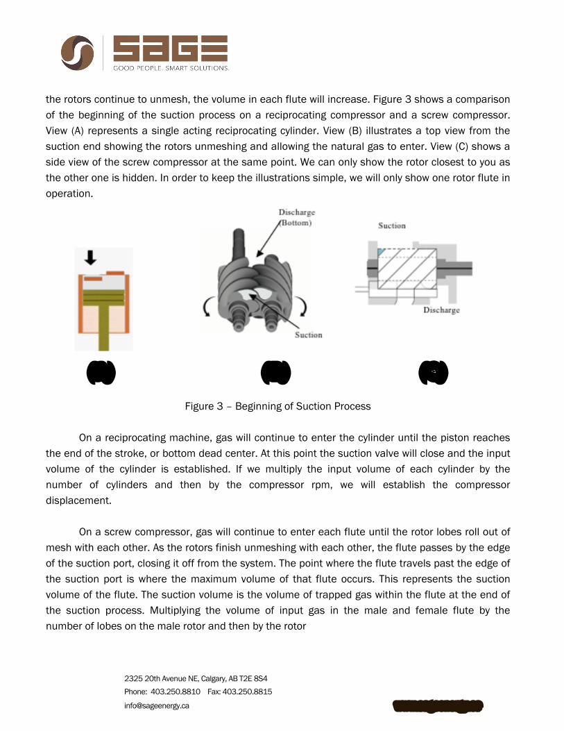
the rotors continue to unmesh, the volume in each flute will increase. Figure 3 shows a comparison of the beginning of the suction process on a reciprocating compressor and a screw compressor. View (A) represents a single acting reciprocating cylinder. View (B) illustrates a top view from the suction end showing the rotors unmeshing and allowing the natural gas to enter. View (C) shows a side view of the screw compressor at the same point. We can only show the rotor closest to you as the other one is hidden. In order to keep the illustrations simple, we will only show one rotor flute in operation.
(A) (B) (C)
Figure 3 – Beginning of Suction Process
On a reciprocating machine, gas will continue to enter the cylinder until the piston reaches
the end of the stroke, or bottom dead center. At this point the suction valve will close and the input volume of the cylinder is established. If we multiply the input volume of each cylinder by the number of cylinders and then by the compressor rpm, we will establish the compressor displacement.
On a screw compressor, gas will continue to enter each flute until the rotor lobes roll out of mesh with each other. As the rotors finish unmeshing with each other, the flute passes by the edge of the suction port, closing it off from the system. The point where the flute travels past the edge of the suction port is where the maximum volume of that flute occurs. This represents the suction volume of the flute. The suction volume is the volume of trapped gas within the flute at the end of the suction process. Multiplying the volume of input gas in the male and female flute by the number of lobes on the male rotor and then by the rotor
2325 20th Avenue NE, Calgary, AB T2E 8S4 Phone: 403.250.8810 Fax: 403.250.8815
[email protected] www.sageenergy.ca
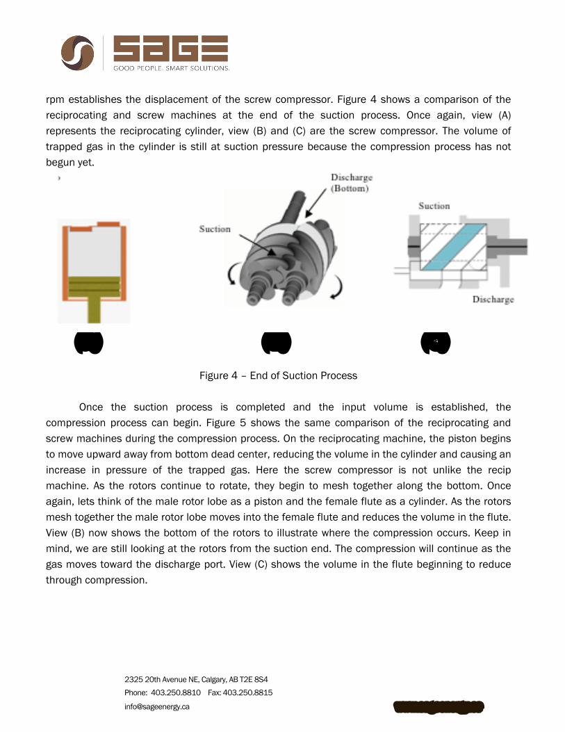
rpm establishes the displacement of the screw compressor. Figure 4 shows a comparison of the reciprocating and screw machines at the end of the suction process. Once again, view (A) represents the reciprocating cylinder, view (B) and (C) are the screw compressor. The volume of trapped gas in the cylinder is still at suction pressure because the compression process has not begun yet.
(A) (B) (C)
Figure 4 – End of Suction Process Once the suction process is completed and the input volume is established, the
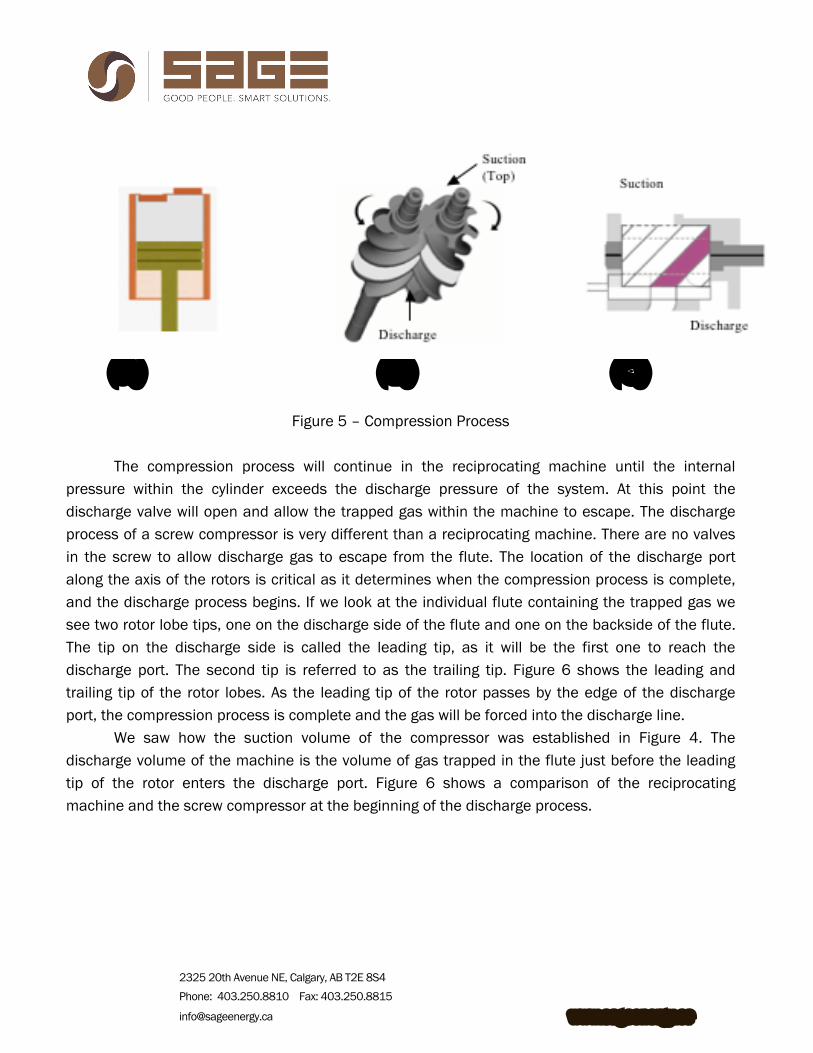
compression process can begin. Figure 5 shows the same comparison of the reciprocating and screw machines during the compression process. On the reciprocating machine, the piston begins to move upward away from bottom dead center, reducing the volume in the cylinder and causing an increase in pressure of the trapped gas. Here the screw compressor is not unlike the recip machine. As the rotors continue to rotate, they begin to mesh together along the bottom. Once again, lets think of the male rotor lobe as a piston and the female flute as a cylinder. As the rotors mesh together the male rotor lobe moves into the female flute and reduces the volume in the flute. View (B) now shows the bottom of the rotors to illustrate where the compression occurs. Keep in mind, we are still looking at the rotors from the suction end. The compression will continue as the gas moves toward the discharge port. View (C) shows the volume in the flute beginning to reduce through compression.
2325 20th Avenue NE, Calgary, AB T2E 8S4 Phone: 403.250.8810 Fax: 403.250.8815
[email protected] www.sageenergy.ca
(A) (B) (C)
Figure 5 – Compression Process
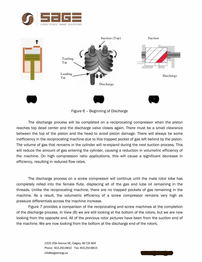
The compression process will continue in the reciprocating machine until the internal pressure within the cylinder exceeds the discharge pressure of the system. At this point the discharge valve will open and allow the trapped gas within the machine to escape. The discharge process of a screw compressor is very different than a reciprocating machine. There are no valves in the screw to allow discharge gas to escape from the flute. The location of the discharge port along the axis of the rotors is critical as it determines when the compression process is complete, and the discharge process begins. If we look at the individual flute containing the trapped gas we see two rotor lobe tips, one on the discharge side of the flute and one on the backside of the flute. The tip on the discharge side is called the leading tip, as it will be the first one to reach the discharge port. The second tip is referred to as the trailing tip. Figure 6 shows the leading and trailing tip of the rotor lobes. As the leading tip of the rotor passes by the edge of the discharge port, the compression process is complete and the gas will be forced into the discharge line.
We saw how the suction volume of the compressor was established in Figure 4. The discharge volume of the machine is the volume of gas trapped in the flute just before the leading tip of the rotor enters the discharge port. Figure 6 shows a comparison of the reciprocating machine and the screw compressor at the beginning of the discharge process.
2325 20th Avenue NE, Calgary, AB T2E 8S4 Phone: 403.250.8810 Fax: 403.250.8815
[email protected] www.sageenergy.ca
(A) (B) (C)
Figure 6 – Beginning of Discharge The discharge process will be completed on a reciprocating compressor when the piston
reaches top dead center and the discharge valve closes again. There must be a small clearance between the top of the piston and the head to avoid piston damage. There will always be some inefficiency in the reciprocating machine due to this trapped pocket of gas left behind by the piston. The volume of gas that remains in the cylinder will re-expand during the next suction process. This will reduce the amount of gas entering the cylinder, causing a reduction in volumetric efficiency of the machine. On high compression ratio applications, this will cause a significant decrease in efficiency, resulting in reduced flow rates.
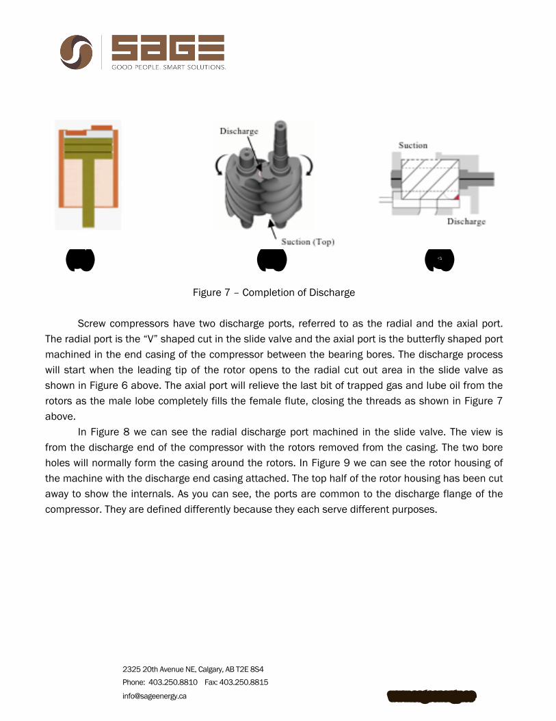
The discharge process on a screw compressor will continue until the male rotor lobe has
completely rolled into the female flute, displacing all of the gas and lube oil remaining in the threads. Unlike the reciprocating machine, there are no trapped pockets of gas remaining in the machine. As a result, the volumetric efficiency of a screw compressor remains very high as pressure differentials across the machine increase.
Figure 7 provides a comparison of the reciprocating and screw machines at the completion of the discharge process. In View (B) we are still looking at the bottom of the rotors, but we are now looking from the opposite end. All of the previous rotor pictures have been from the suction end of the machine. We are now looking from the bottom at the discharge end of the rotors.
2325 20th Avenue NE, Calgary, AB T2E 8S4 Phone: 403.250.8810 Fax: 403.250.8815
[email protected] www.sageenergy.ca
(A) (B) (C)
Figure 7 – Completion of Discharge Screw compressors have two discharge ports, referred to as the radial and the axial port.
The radial port is the “V” shaped cut in the slide valve and the axial port is the butterfly shaped port machined in the end casing of the compressor between the bearing bores. The discharge process will start when the leading tip of the rotor opens to the radial cut out area in the slide valve as shown in Figure 6 above. The axial port will relieve the last bit of trapped gas and lube oil from the rotors as the male lobe completely fills the female flute, closing the threads as shown in Figure 7 above.
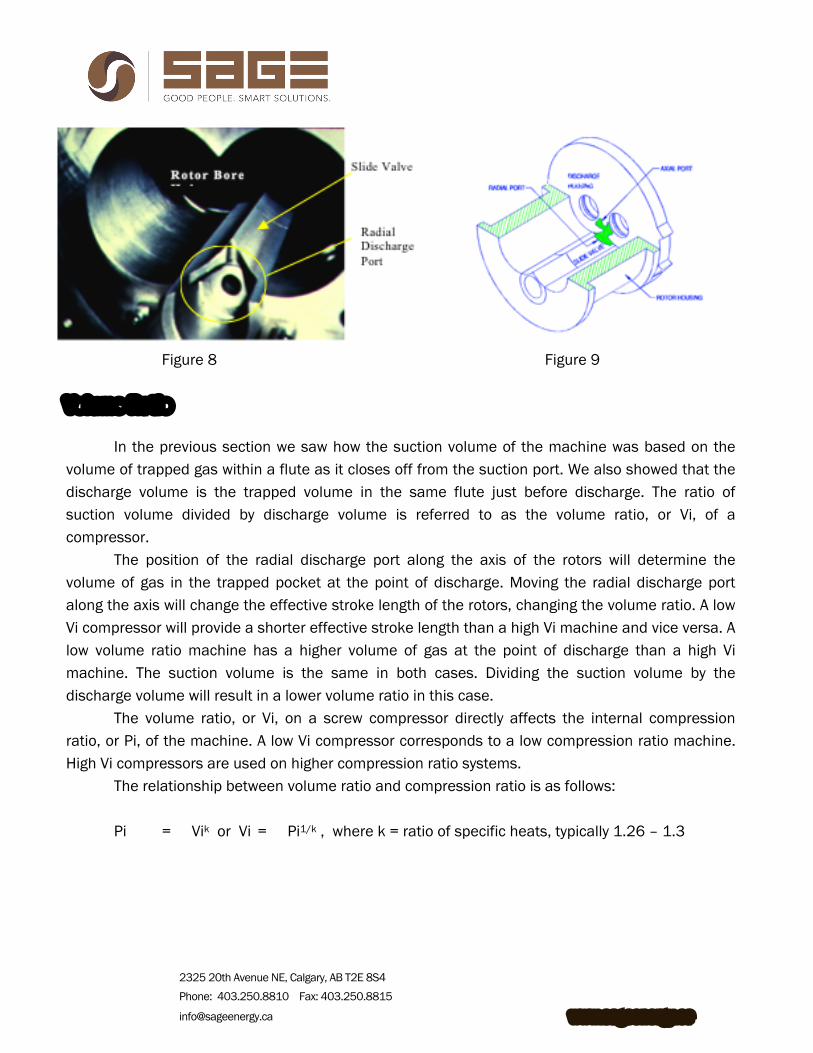
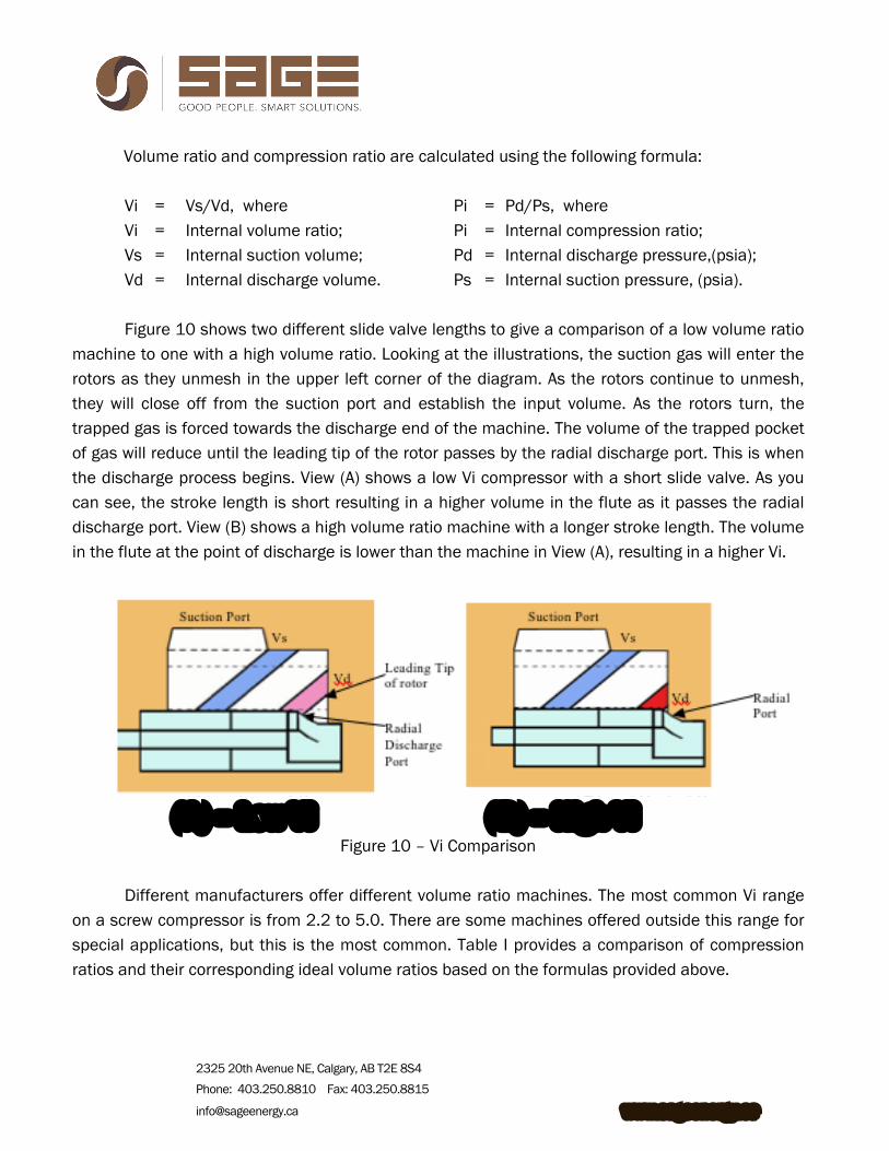
In Figure 8 we can see the radial discharge port machined in the slide valve. The view is from the discharge end of the compressor with the rotors removed from the casing. The two bore holes will normally form the casing around the rotors. In Figure 9 we can see the rotor housing of the machine with the discharge end casing attached. The top half of the rotor housing has been cut away to show the internals. As you can see, the ports are common to the discharge flange of the compressor. They are defined differently because they each serve different purposes.
2325 20th Avenue NE, Calgary, AB T2E 8S4 Phone: 403.250.8810 Fax: 403.250.8815
[email protected] www.sageenergy.ca
Figure 8 Figure 9 Volume Ratio
In the previous section we saw how the suction volume of the machine was based on the volume of trapped gas within a flute as it closes off from the suction port. We also showed that the discharge volume is the trapped volume in the same flute just before discharge. The ratio of suction volume divided by discharge volume is referred to as the volume ratio, or Vi, of a compressor.
The position of the radial discharge port along the axis of the rotors will determine the volume of gas in the trapped pocket at the point of discharge. Moving the radial discharge port along the axis will change the effective stroke length of the rotors, changing the volume ratio. A low Vi compressor will provide a shorter effective stroke length than a high Vi machine and vice versa. A low volume ratio machine has a higher volume of gas at the point of discharge than a high Vi machine. The suction volume is the same in both cases. Dividing the suction volume by the discharge volume will result in a lower volume ratio in this case.
The volume ratio, or Vi, on a screw compressor directly affects the internal compression ratio, or Pi, of the machine. A low Vi compressor corresponds to a low compression ratio machine. High Vi compressors are used on higher compression ratio systems.
The relationship between volume ratio and compression ratio is as follows: Pi = Vik or Vi = Pi1/k , where k = ratio of specific heats, typically 1.26 – 1.3
2325 20th Avenue NE, Calgary, AB T2E 8S4 Phone: 403.250.8810 Fax: 403.250.8815
[email protected] www.sageenergy.ca
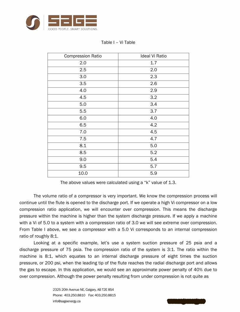
Volume ratio and compression ratio are calculated using the following formula: Vi = Vs/Vd, where Pi = Pd/Ps, where Vi = Internal volume ratio; Pi = Internal compression ratio; Vs = Internal suction volume; Pd = Internal discharge pressure,(psia); Vd = Internal discharge volume. Ps = Internal suction pressure, (psia). Figure 10 shows two different slide valve lengths to give a comparison of a low volume ratio
machine to one with a high volume ratio. Looking at the illustrations, the suction gas will enter the rotors as they unmesh in the upper left corner of the diagram. As the rotors continue to unmesh, they will close off from the suction port and establish the input volume. As the rotors turn, the trapped gas is forced towards the discharge end of the machine. The volume of the trapped pocket of gas will reduce until the leading tip of the rotor passes by the radial discharge port. This is when the discharge process begins. View (A) shows a low Vi compressor with a short slide valve. As you can see, the stroke length is short resulting in a higher volume in the flute as it passes the radial discharge port. View (B) shows a high volume ratio machine with a longer stroke length. The volume in the flute at the point of discharge is lower than the machine in View (A), resulting in a higher Vi.
(A) – Low Vi (B) – High Vi
Figure 10 – Vi Comparison
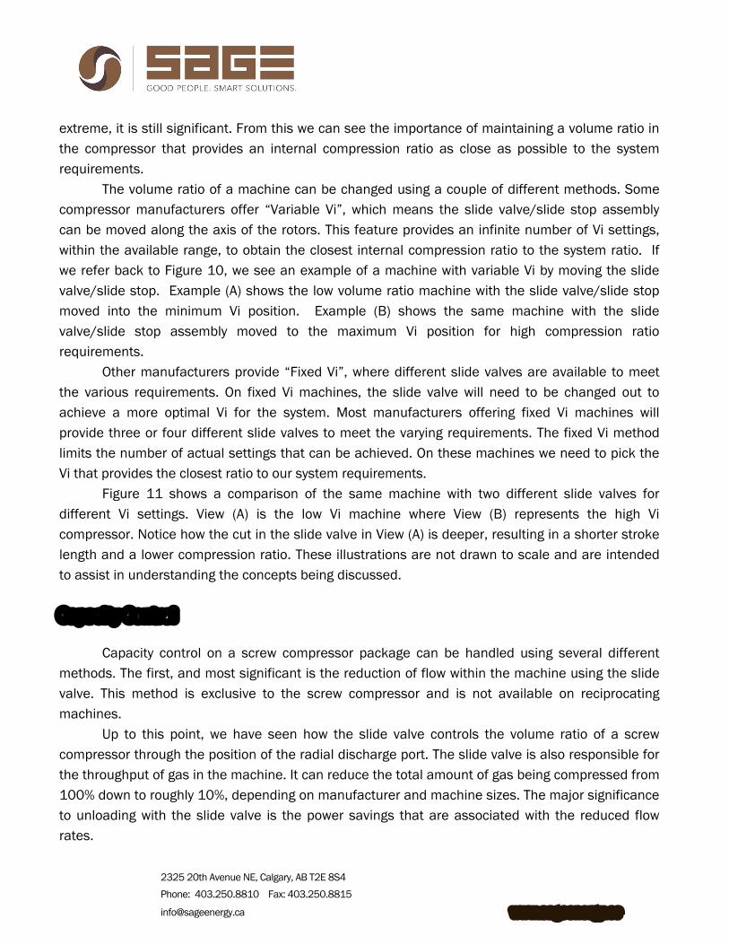
Different manufacturers offer different volume ratio machines. The most common Vi range on a screw compressor is from 2.2 to 5.0. There are some machines offered outside this range for special applications, but this is the most common. Table I provides a comparison of compression ratios and their corresponding ideal volume ratios based on the formulas provided above.
2325 20th Avenue NE, Calgary, AB T2E 8S4 Phone: 403.250.8810 Fax: 403.250.8815
[email protected] www.sageenergy.ca
Table I – Vi Table
Compression Ratio Ideal Vi Ratio
2.0 1.7 2.5 2.0 3.0 2.3 3.5 2.6 4.0 2.9 4.5 3.2 5.0 3.4 5.5 3.7 6.0 4.0 6.5 4.2 7.0 4.5 7.5 4.7 8.1 5.0 8.5 5.2 9.0 5.4 9.5 5.7
10.0 5.9
The above values were calculated using a “k” value of 1.3. The volume ratio of a compressor is very important. We know the compression process will
continue until the flute is opened to the discharge port. If we operate a high Vi compressor on a low compression ratio application, we will encounter over compression. This means the discharge pressure within the machine is higher than the system discharge pressure. If we apply a machine with a Vi of 5.0 to a system with a compression ratio of 3.0 we will see extreme over compression. From Table I above, we see a compressor with a 5.0 Vi corresponds to an internal compression ratio of roughly 8:1.
Looking at a specific example, let’s use a system suction pressure of 25 psia and a discharge pressure of 75 psia. The compression ratio of the system is 3:1. The ratio within the machine is 8:1, which equates to an internal discharge pressure of eight times the suction pressure, or 200 psi, when the leading tip of the flute reaches the radial discharge port and allows the gas to escape. In this application, we would see an approximate power penalty of 40% due to over compression. Although the power penalty resulting from under compression is not quite as
2325 20th Avenue NE, Calgary, AB T2E 8S4 Phone: 403.250.8810 Fax: 403.250.8815
[email protected] www.sageenergy.ca
extreme, it is still significant. From this we can see the importance of maintaining a volume ratio in the compressor that provides an internal compression ratio as close as possible to the system requirements.
The volume ratio of a machine can be changed using a couple of different methods. Some compressor manufacturers offer “Variable Vi”, which means the slide valve/slide stop assembly can be moved along the axis of the rotors. This feature provides an infinite number of Vi settings, within the available range, to obtain the closest internal compression ratio to the system ratio. If we refer back to Figure 10, we see an example of a machine with variable Vi by moving the slide valve/slide stop. Example (A) shows the low volume ratio machine with the slide valve/slide stop moved into the minimum Vi position. Example (B) shows the same machine with the slide valve/slide stop assembly moved to the maximum Vi position for high compression ratio requirements.
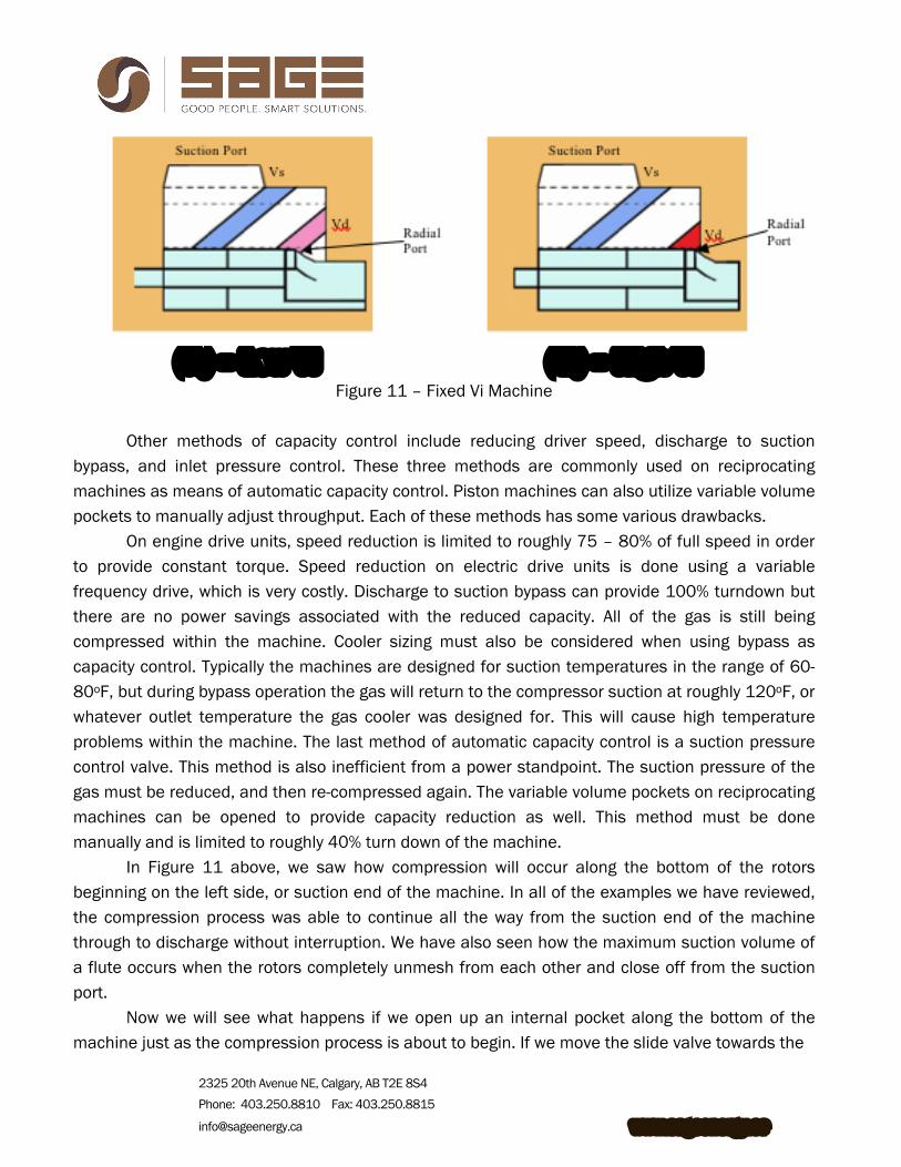
Other manufacturers provide “Fixed Vi”, where different slide valves are available to meet the various requirements. On fixed Vi machines, the slide valve will need to be changed out to achieve a more optimal Vi for the system. Most manufacturers offering fixed Vi machines will provide three or four different slide valves to meet the varying requirements. The fixed Vi method limits the number of actual settings that can be achieved. On these machines we need to pick the Vi that provides the closest ratio to our system requirements.
Figure 11 shows a comparison of the same machine with two different slide valves for different Vi settings. View (A) is the low Vi machine where View (B) represents the high Vi compressor. Notice how the cut in the slide valve in View (A) is deeper, resulting in a shorter stroke length and a lower compression ratio. These illustrations are not drawn to scale and are intended to assist in understanding the concepts being discussed.
Capacity Control
Capacity control on a screw compressor package can be handled using several different methods. The first, and most significant is the reduction of flow within the machine using the slide valve. This method is exclusive to the screw compressor and is not available on reciprocating machines.
Up to this point, we have seen how the slide valve controls the volume ratio of a screw compressor through the position of the radial discharge port. The slide valve is also responsible for the throughput of gas in the machine. It can reduce the total amount of gas being compressed from 100% down to roughly 10%, depending on manufacturer and machine sizes. The major significance to unloading with the slide valve is the power savings that are associated with the reduced flow rates.
2325 20th Avenue NE, Calgary, AB T2E 8S4 Phone: 403.250.8810 Fax: 403.250.8815
[email protected] www.sageenergy.ca
(A) – Low Vi (B) – High Vi Figure 11 – Fixed Vi Machine
Other methods of capacity control include reducing driver speed, discharge to suction
bypass, and inlet pressure control. These three methods are commonly used on reciprocating machines as means of automatic capacity control. Piston machines can also utilize variable volume pockets to manually adjust throughput. Each of these methods has some various drawbacks.
On engine drive units, speed reduction is limited to roughly 75 – 80% of full speed in order to provide constant torque. Speed reduction on electric drive units is done using a variable frequency drive, which is very costly. Discharge to suction bypass can provide 100% turndown but there are no power savings associated with the reduced capacity. All of the gas is still being compressed within the machine. Cooler sizing must also be considered when using bypass as capacity control. Typically the machines are designed for suction temperatures in the range of 60-80oF, but during bypass operation the gas will return to the compressor suction at roughly 120oF, or whatever outlet temperature the gas cooler was designed for. This will cause high temperature problems within the machine. The last method of automatic capacity control is a suction pressure control valve. This method is also inefficient from a power standpoint. The suction pressure of the gas must be reduced, and then re-compressed again. The variable volume pockets on reciprocating machines can be opened to provide capacity reduction as well. This method must be done manually and is limited to roughly 40% turn down of the machine.
In Figure 11 above, we saw how compression will occur along the bottom of the rotors beginning on the left side, or suction end of the machine. In all of the examples we have reviewed, the compression process was able to continue all the way from the suction end of the machine through to discharge without interruption. We have also seen how the maximum suction volume of a flute occurs when the rotors completely unmesh from each other and close off from the suction port.
Now we will see what happens if we open up an internal pocket along the bottom of the machine just as the compression process is about to begin. If we move the slide valve towards the
2325 20th Avenue NE, Calgary, AB T2E 8S4 Phone: 403.250.8810 Fax: 403.250.8815
[email protected] www.sageenergy.ca
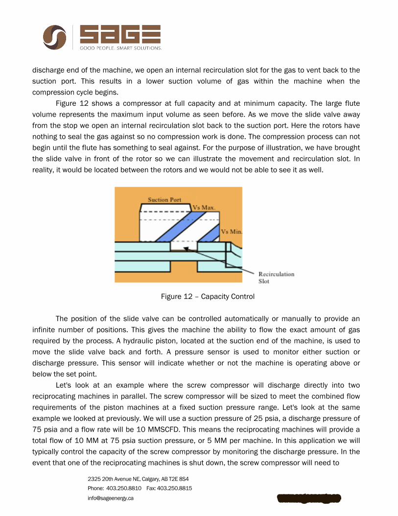
discharge end of the machine, we open an internal recirculation slot for the gas to vent back to the suction port. This results in a lower suction volume of gas within the machine when the compression cycle begins.
Figure 12 shows a compressor at full capacity and at minimum capacity. The large flute volume represents the maximum input volume as seen before. As we move the slide valve away from the stop we open an internal recirculation slot back to the suction port. Here the rotors have nothing to seal the gas against so no compression work is done. The compression process can not begin until the flute has something to seal against. For the purpose of illustration, we have brought the slide valve in front of the rotor so we can illustrate the movement and recirculation slot. In reality, it would be located between the rotors and we would not be able to see it as well.
Figure 12 – Capacity Control The position of the slide valve can be controlled automatically or manually to provide an
infinite number of positions. This gives the machine the ability to flow the exact amount of gas required by the process. A hydraulic piston, located at the suction end of the machine, is used to move the slide valve back and forth. A pressure sensor is used to monitor either suction or discharge pressure. This sensor will indicate whether or not the machine is operating above or below the set point.
Let's look at an example where the screw compressor will discharge directly into two reciprocating machines in parallel. The screw compressor will be sized to meet the combined flow requirements of the piston machines at a fixed suction pressure range. Let's look at the same example we looked at previously. We will use a suction pressure of 25 psia, a discharge pressure of 75 psia and a flow rate will be 10 MMSCFD. This means the reciprocating machines will provide a total flow of 10 MM at 75 psia suction pressure, or 5 MM per machine. In this application we will typically control the capacity of the screw compressor by monitoring the discharge pressure. In the event that one of the reciprocating machines is shut down, the screw compressor will need to

2325 20th Avenue NE, Calgary, AB T2E 8S4 Phone: 403.250.8810 Fax: 403.250.8815
[email protected] www.sageenergy.ca
unload or reduce the flow rate by 50% to prevent the reciprocating machine from overloading the engine. The discharge pressure sensor will sense an increase in the discharge pressure and send a signal back to the control system telling it to unload the machine. Lube oil from the system will be directed through a four way directional valve to the backside of the hydraulic piston, forcing it to move the slide valve towards the discharge end of the machine. This will reduce the throughput of gas in the compressor until it reaches the desired rate of 5 MM.
Once the down stream compressor is started up again, the discharge pressure will begin to fall as the reciprocating machines take away the gas. The pressure sensor will provide a signal to load the machine and oil will be pumped through another port on the directional valve back to the other side of the piston, forcing the slide valve towards the suction end until the desired pressure is reached. If you are unsure of where the hydraulic cylinder is located, please refer back to Figure 2 earlier in the paper.
Operating at half capacity as we saw in the above example provides significant power savings as well. Figure 13 below shows the typical part load power consumption of a screw compressor at various different compression ratios. At low ratios, the offload power consumption is better than the high ratio machines. These power savings are significantly higher than reciprocating machines.
Figure 13 – Part Load Power Curve at Various System
Compression Ratios
2325 20th Avenue NE, Calgary, AB T2E 8S4 Phone: 403.250.8810 Fax: 403.250.8815
[email protected] www.sageenergy.ca
Lube Oil System
As we mentioned at the beginning of this paper, the machines we are looking at are oil flooded compressors. These machines require large amounts of lube oil to provide sealing between the rotor lobes and the casing, and the male and female lobes where the compression occurs. The oil is also required for lubrication of the bearings and shaft seals, and to reduce the heat of compression in the machine.
The lube oil system on a screw compressor is a closed loop system. The oil is injected into the machine in several places. The main oil injection port feeds the rotors directly with smaller lines feeding various points on the machine for seals and bearings. Once the oil is injected, passages within the machine will drain all the bearing and seal oil into the rotors where it combines with the gas. The gas and oil mixture is then discharged out of the machine. The oil that is injected must be removed from the gas down stream of the compressor.
A separate oil separator vessel is required to remove this oil from the gas. This vessel can be either vertical or horizontal in design, depending on equipment layouts and availability of space. The vessel will require coalescing type elements to remove as much oil as possible. Typical oil carry over rates from the separator are in the 10 ppm range. The oil separator also acts as a reservoir for the lube oil system. The lube oil will flow from the bottom of the separator, through an oil cooler where it is cooled from discharge temperature down to 140-160oF, through an oil filter and then back to the machine. Depending on the compressor manufacturer and the operating conditions, some machines require lube oil pumps to circulate the oil. Other manufacturers will use the differential pressure from discharge to suction to move the oil around the system.
The oil cooling can be done using two different methods. The direct cooling method simply uses a section in the after cooler to cool the oil using the ambient air. The indirect method cools the oil in a shell and tube or plate and frame cooler. A water/glycol mixture is pumped through the other side of the exchanger and then circulated through a section in the gas after cooler. This method requires an additional exchanger and water pump.
There are various arguments supporting each method. We have found the indirect cooling to be the most useful in our applications. It is particularly important to use this method in areas where cold ambient temperatures occur and the units are provided in heated buildings rather than outside. Here the oil is kept inside the building and not exposed to freezing temperatures. Direct cooling methods are not effective in cooler climates. Any oil left in an aerial cooler in cold weather during shut down periods will become more viscous and difficult to move around the system. In areas where the temperatures are warmer, direct cooling methods are seen more often. In these applications, vendors much choose the most effective and reliable methods for their clients. Although additional oil coolers and water pumps are required on the indirect systems, the cost of

2325 20th Avenue NE, Calgary, AB T2E 8S4 Phone: 403.250.8810 Fax: 403.250.8815
[email protected] www.sageenergy.ca
the aerial cooler increases with direct cooling as oil requires more surface area in the cooler than a water/glycol mixture. Another factor we need to consider is the amount of oil in the system. The direct cooling method will require much more lube oil than the indirect system. The oil used in these systems is typically a synthetic product that is much more expensive than a water/glycol mixture.
Screw Compressor Package Components
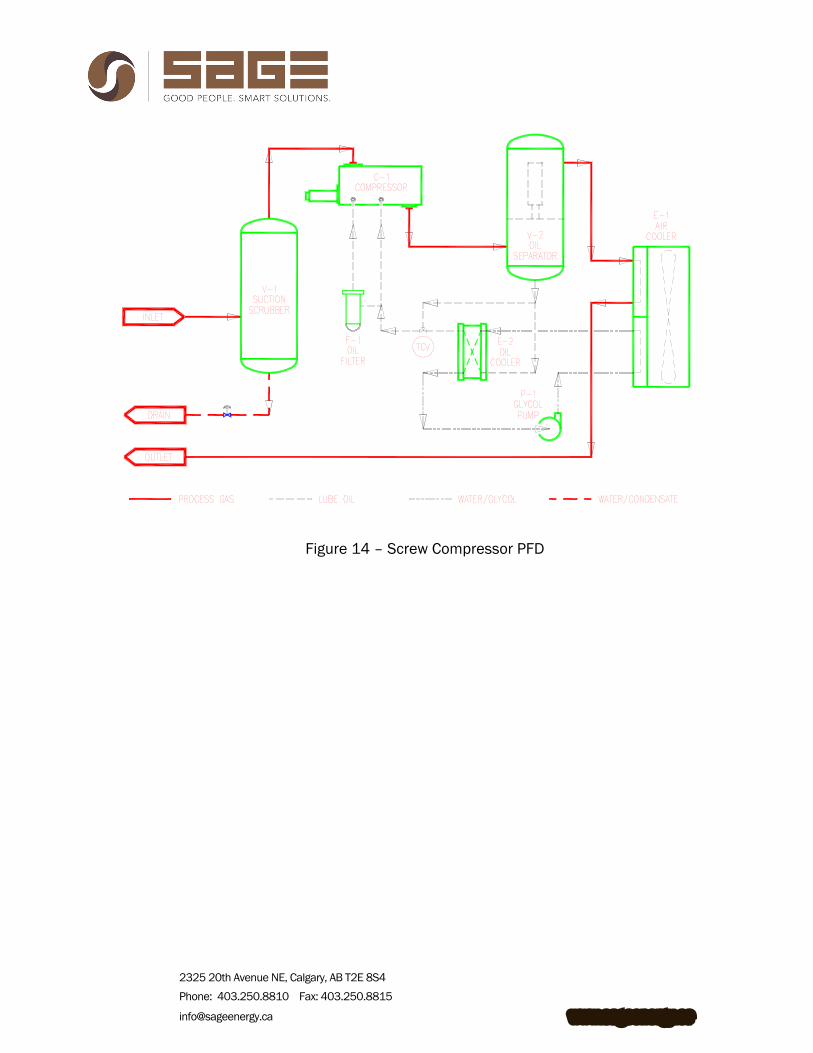
With the exception of the oil separator and the oil cooling system, most of the components on a screw compressor package are similar to a reciprocating machine. Figure 14 provides an illustration of a typical process flow diagram for a natural gas screw compressor package. The inlet gas is fed through a suction scrubber or filter to remove any free liquids and particulate. Liquids are drained from the vessel to skid edge and the gas is taken off the top and fed into the compressor where it mixes with the lube oil. The high pressure gas is fed through the oil separator where the oil is removed to accumulate in the bottom of the vessel. The gas is then sent to the after cooler where it is cooled from normal discharge temperatures of 170-220oF down to 120oF. These temperatures will vary a little depending on different requirements and ambient conditions. The cooled gas is then taken off skid for connection to the field piping.
The lube oil will flow from the bottom of the oil separator through an oil cooler into the main oil header. The header splits into two main feed points for the compressor. Some of the oil is filtered down to roughly 10 microns and then injected into the bearings and shaft seal. The remaining oil is injected directly into the rotors.
We have labeled the process gas, compressor lube oil, water/glycol for compressor oil cooling and water/condensate drain lines.
2325 20th Avenue NE, Calgary, AB T2E 8S4 Phone: 403.250.8810 Fax: 403.250.8815
[email protected] www.sageenergy.ca
Figure 14 – Screw Compressor PFD
2325 20th Avenue NE, Calgary, AB T2E 8S4 Phone: 403.250.8810 Fax: 403.250.8815
[email protected] www.sageenergy.ca
CONCLUSION
In recent years, declining pressures in natural gas fields have made rotary screw
compressors a very attractive alternative and supplement to reciprocating machines. We know that screw compressors are not designed to compete against the reciprocating market in all applications. Screws are low pressure machines, designed to operate up to roughly 350 psig discharge pressure. They are not designed to operate at the same high pressures that piston machines can achieve.
Even with their growing popularity, very few people understand how screw compressors actually operate. We have looked at a comparison of the compression process of a screw machine to a reciprocating machine. We have seen that screw compressors do not have any suction and discharge valves that open and close automatically based on pressure differential across them. Screws require proper positioning of the radial discharge port to control volume ratio, which is ultimately required to match the internal compression ratio of the machine to the system requirements.
We reviewed the concept of capacity control using the slide valve, and the power savings associated with the reduced capacity. We have looked at the lube oil system, why it is required, and how it operates. We also reviewed the overall screw compressor package to see what major components were required to make the system operational.
Screw compressors are not designed to replace reciprocating machines. They are designed to provide a very flexible, highly reliable alternative for low pressure applications.
ACKNOWLEDGMENTS We would like to thank Frick and Ariel Corporation for their co-operation in providing some of
the graphics and information presented in this paper. Their help was greatly appreciated.