an investigation in techniques used to procedurally ... · an investigation in techniques used to...
TRANSCRIPT

An Investigation in Techniques used to Procedurally Generate Dungeon Structures 1
An Investigation in Techniques used to Procedurally Generate Dungeon Structures
By: Nathan Williams

An Investigation in Techniques used to Procedurally Generate Dungeon Structures 2
Abstract
This project takes a look at understanding the ever increasingly popular topic of procedural content generation and it uses to generate structures that can be used as levels inside video games. With a focus on dungeon generation, several techniques are explored and compared to each other
to gain an understanding of where each one may be appropriate to be used. Due to a desire to improve current techniques, new approaches are investigated and developed to help with some of
the common problems found in dungeon generation.

An Investigation in Techniques used to Procedurally Generate Dungeon Structures 3
1 TABLE OF CONTENTS
1 TABLE OF CONTENTS .............................................................................................................. 3
2 INTRODUCTION ...................................................................................................................... 6
2.1 BRIEF .................................................................................................................................... 6
2.1.1 WHAT IS A DUNGEON? .................................................................................................................... 6
2.1.2 WHY DUNGEONS?........................................................................................................................... 8
2.2 PRODUCT ............................................................................................................................... 8
2.3 EXISTING TECHNIQUES FOR GENERATING DUNGEONS ....................................................................... 9
2.3.1 BINARY SPACE PARTITIONING BASED DUNGEONS .................................................................................. 9
2.3.2 DELAUNAY TRIANGULATION DUNGEONS ........................................................................................... 13
2.3.3 GRAPH GRAMMARS ....................................................................................................................... 16
2.3.4 CELLULAR AUTOMATA .................................................................................................................... 18
RESEARCH CONCLUSION .................................................................................................................. 19
3 DESIGN ................................................................................................................................ 20
3.1 INTRODUCTION ..................................................................................................................... 20
3.2 TECHNOLOGY CHOICE ............................................................................................................. 20
3.2.1 UNITY .......................................................................................................................................... 20
3.2.2 DIREXTX/OPENGL ................................................................................................................... 21
3.2.3 LIBGDX ....................................................................................................................................... 21
3.2.4 CONCLUSION ................................................................................................................................ 21
3.3 EVALUATION STRATEGY ........................................................................................................... 22
3.3.1 PRODUCT EVALUATION .................................................................................................................. 22
3.3.2 PROJECT EVALUATION .................................................................................................................... 22
4 DEVELOPMENT ..................................................................................................................... 23
4.1 DELAUNAY DUNGEON GENERATION ........................................................................................... 23
4.2 BINARY SPACE PARTITIONING DUNGEON GENERATION ................................................................... 30
4.3 CELLULAR AUTOMATA GENERATION ........................................................................................... 34
5 TEST EVALUATION ................................................................................................................ 36
5.1 IS THE STRUCTURE A DUNGEON ................................................................................................. 36
5.2 IMPLEMENTATION DIFFICULTY .................................................................................................. 36
5.3 GENERATION TIME ................................................................................................................. 37
5.3.1 DELAUNAY GENERATION ................................................................................................................ 37
5.3.2 BSP GENERATION ......................................................................................................................... 38
5.3.3 CELLULAR AUTOMATA GENERATION ................................................................................................. 39
5.3.4 ANALYSIS ..................................................................................................................................... 40
5.4 MEMORY USAGE ................................................................................................................... 41
5.4.1 DELAUNAY GENERATION ................................................................................................................ 41
5.4.2 BSP GENERATION ......................................................................................................................... 42
5.4.3 CELLULAR AUTOMATA GENERATION ................................................................................................. 43
5.4.4 ANALYSIS ..................................................................................................................................... 44
5.5 PRODUCT SWOT ANALYSIS ..................................................................................................... 45

An Investigation in Techniques used to Procedurally Generate Dungeon Structures 4
5.5.1 STRENGTHS .................................................................................................................................. 45
5.5.2 WEAKNESSES ................................................................................................................................ 45
5.5.3 OPPORTUNITIES ............................................................................................................................ 45
5.5.4 THREATS ...................................................................................................................................... 45
6 CONCLUSION ........................................................................................................................ 46
6.1 PROJECT EVALUATION ............................................................................................................. 46
6.2 FURTHER RESEARCH ............................................................................................................... 46
6.3 PROJECT CONCLUSION ............................................................................................................ 47
7 APPENDIX ............................................................................................................................ 48
7.1 APPENDIX A – DUNGEON TILESET .............................................................................................. 48
7.2 APPENDIX B – DELAUNAY GENERATION TIME RESULTS .................................................................. 49
7.3 APPENDIX C – BSP GENERATION TIME RESULTS ............................................................................ 51
7.4 APPENDIX D – CELLULAR AUTOMATA GENERATION TIME RESULTS..................................................... 53
7.5 APPENDIX E – DELAUNAY GENERATION MEMORY RESULTS .............................................................. 55
7.6 APPENDIX F – BSP GENERATION MEMORY RESULTS ...................................................................... 55
7.7 APPENDIX G – CELLULAR AUTOMATA GENERATION MEMORY RESULTS .............................................. 55
7.8 APPENDIX H – FIRST TERM DEVELOPMENT TIMETABLE ................................................................... 56
7.9 APPENDIX I – SECOND TERM DEVELOPMENT TIMETABLE ................................................................. 57
8 BIBLIOGRAPHY ..................................................................................................................... 58

An Investigation in Techniques used to Procedurally Generate Dungeon Structures 5
Figure 2.1– Screenshot from Rouge, showing the shape of the games dungeons ...................................... 7 Figure 2.2 - Overview of a dungeon from The Legend of Zelda: A Link to the Past .................................. 7 Figure 2.3 – Screenshot of a level from Spelunky .................................................................................................. 8 Figure 2.4- Visual representation of dungeon space after one BSP split Retrieved from: http://roguebasin.roguelikedevelopment.org/index.php?title=Basic_BSP_Dungeon_generation 9 Figure 2.5 – BSP Tree representation of dungeon space after one BSP split .............................................. 9 Figure 2.6 - BSP Tree representation of dungeon space after two BSP splits .......................................... 10 Figure 2.7– Visual representation of dungeon space after two BSP splits ................................................ 10 Figure 2.8 – Visual representation of dungeon space after four BSP splits .............................................. 10 Figure 2.9 – Visual representation of dungeon space after dungeon rooms added to leaf node ..... 11 Figure 2.10 –Visual representation of dungeon space after leaf node sibling rooms connected ...... 12 Figure 2.11 – Visual representation of fully connected dungeon ................................................................. 12 Figure 2.12 – Development screenshot of TinyKeep by PhiGames ............................................................... 13 Figure 2.13 – Generation of cells with rectangles. ............................................................................................. 13 Figure 2.14 – Layout of cells after separation steering behaviour applied .............................................. 14 Figure 2.15 – Final graph created by combining the Delaunay triangulation with the minimal spanning tree. .................................................................................................................................................................. 14 Figure 2.16 – Example graph .................................................................................................................................... 16 Figure 2.17– Example substitution rule ................................................................................................................. 16 Figure 2.18 – Example graph after substitution ................................................................................................. 16 Figure 2.19– Shape grammar showing alphabet, rules and output. ........................................................... 17 Figure 2.20 – Comparison grid showing results of background research ................................................. 19 Figure 3.1 – Technology choice comparison grid ............................................................................................... 21 Figure 4.1– Inverse Square Law Separation formula ....................................................................................... 23 Figure 4.2– Algorithm to find if a vertex is inside a hull .................................................................................. 23 Figure 4.3– Function to calculate if point is inside triangle ........................................................................... 24 Figure 4.4– Vertex being added to triangulation ............................................................................................... 24 Figure 4.5– Illustration of Lawson flip in action ................................................................................................ 25 Figure 4.6 – Illustration of quadrilateral of Incident edge ............................................................................. 25 Figure 4.7– Screenshot of dungeon created by implementation .................................................................. 26 Figure 4.8– Corridor Digger movement algorithm............................................................................................ 27 Figure 4.9– Hashing Value Grid ................................................................................................................................ 28 Figure 4.10– Grid representation of tiles in dungeon ....................................................................................... 28 Figure 4.11– Grid representation of tiles in dungeon with hash value grid overlaid ........................... 28 Figure 4.12– Screenshot of final output of Delaunay generation ................................................................ 29 Figure 4.13– Representation of BSPNode class ................................................................................................... 30 Figure 4.14– Screenshot of output after 5 BSP splits ........................................................................................ 31 Figure 4.15– Representation of rooms in dungeon with connections......................................................... 32 Figure 4.16– Visualization of Delaunay connection strategy ........................................................................ 32 Figure 4.17– Visualization of Transitive Connect strategy ............................................................................ 33 Figure 4.18– Screenshot of final output of BSP generation ............................................................................ 33 Figure 4.19 – pseudo-code for the 4-5 rule......................................................................................................... 34 Figure 4.20 – Screenshot of outputted structured of Cellular Automata generation ........................... 35 Figure 5.1 – Grid of generation types compared against dungeon criteria .............................................. 36 Figure 5.2 – Grid of generation types compared to difficulty criteria ........................................................ 36 Figure 5.3 – Graph of Delaunay generation time with different room amounts .................................... 37 Figure 5.4 – Graph of BSP generation time with different room amounts ............................................... 38 Figure 5.5 - Graph of Cellular Automata generation time with different grid sizes .............................. 39 Figure 5.6 – Graph of BSP and Delaunay generation time comparison ..................................................... 40 Figure 5.7 - Graph of Delaunay RAM usage with different room amounts ............................................... 41 Figure 5.8 - Graph of BSP RAM usage with different room amounts .......................................................... 42 Figure 5.9 – Graph of Cellular Automata RAM Usage with different grid sizes ...................................... 43 Figure 5.10 - Graph of BSP and Delaunay RAM usage comparison ............................................................. 44

An Investigation in Techniques used to Procedurally Generate Dungeon Structures 6
2 INTRODUCTION
2.1 BRIEF
Procedural Content Generation (PCG) is the “algorithmic creation of anything from background scenery to symphonies to storylines” (Lambe, 2012). PCG has been used in video games since the early 1980’s when “the limited capabilities of home computers in the early eighties constrained the space available to store game content” (Togelius, 2013). In modern times there are several advantages to developers when using PCG in games development. The use of PCG allows game developers to create large amounts of diverse game content in a much smaller time frame than it would have taken to make that content manually. An example of this is Borderlands 2 (Gearbox Software, 2012) where all the collectables in the game “are randomly generated so no two pieces of gear are the same” (Gearbox Software, 2012). PCG has also grown in use in Indie game development. Due to teams often being fairly small, the possibility to create large amounts of content procedurally that would have otherwise not been possible with a small team, becomes an attractive option. Minecraft (Mojang, 2009) an Indie game originally created by a single developer, used PCG to generate the entire game world which is “nine hundred million square kilometres” (Persson, 2010) in size.
Level generation is a diverse topic in PCG as there are large variations on the characteristic of a level between different games. However in a lot of cases well known structures can be used, for example:
Dungeon structure
Cave structure
Island structure
Maze structure
Due to each of these subsections being large research areas in themselves the focus of this investigation will be largely on dungeon generation.
2.1.1 WHAT IS A DUNGEON?
Dungeon structures in video games have largely been connected with the ‘dungeon crawler’ and ‘rouge-likes’ genres of video games. These styles of games evolve around players exploring labyrinth style mazes in search of treasure. One of the earliest uses of dungeons was in the game Rouge (Wichman, 1980) which used ASCII graphics to represent procedurally generated dungeons that consisted of square rooms connected together with corridors, as can be seen in Figure 2.1. Each ASCII character represents a different element of the dungeon, for example the ‘@’ symbol is the players location and the ‘#’ is a corridor.

An Investigation in Techniques used to Procedurally Generate Dungeon Structures 7
Figure 2.1– Screenshot from
Rouge, showing the shape of the games dungeons Retrieved from:
http://www.gamasutra.com/db_area/images/feature/40
13/0601.jpg
As hardware evolved so have dungeons in video games. The Legend of Zelda: A Link to the Past (Nintendo, 1991) has hand crafted dungeons with similarities to the ones in Rouge (Wichman, 1980) except with the notable difference that there are no corridors between rooms, and all rooms are a uniform sized and aligned on a grid, as can be seen in Figure 2.2.
Figure 2.2 - Overview of a dungeon from The Legend of Zelda: A Link to the Past
Retrieved from: http://www.zeldacapital.com/Games/maps_la/color_dungeon.png

An Investigation in Techniques used to Procedurally Generate Dungeon Structures 8
Both the previous examples demonstrate dungeons for games with a top down perspective of the game world. There are games that fit into the ‘platformer’ genre that have levels that consist of dungeon like structures using a side on perspective of the game world. Spelunky (Mossmouth , 2013) uses a mixture of hand crafted segments/rooms procedurally placed together to create its dungeon like levels, as can be seen in Figure 2.3.
Figure 2.3 – Screenshot of a level from Spelunky
Retrieved from: http://spelunkyworld.com/images/spelunky-ss12.jpg
All the mentioned dungeons share a common characteristic. They are created using a ‘room’ structure of some form and a method to connect the ‘rooms’ together.
2.1.2 WHY DUNGEONS?
Dungeon structures can cover a diverse range of modifications allowing them the potential to be used in a large number of games. In the Indie game development scene there is an increasing number of games in development that are using procedurally generated dungeons. Some of these include:
Tinykeep (Phigames, 2013)
Delver (Priority Interrupt, 2013)
Dungeon Hearts 2 (Cube Roots, 2013)
Chasm (Discord Games LLC, 2013)
The recent increase in interest in the topic of procedural dungeon generation has created several discussions across the internet on techniques that could be used to solve the problem and developers sharing techniques they have invented with one another, making the timing appropriate for an investigation on the topic.
2.2 PRODUCT
The outcome of this research project will be several prototype programs that show off unique dungeon generation methods.
The target users for the research in this report will be game developers interested in creating procedurally generated levels for their projects.

An Investigation in Techniques used to Procedurally Generate Dungeon Structures 9
2.3 EXISTING TECHNIQUES FOR GENERATING DUNGEONS
2.3.1 BINARY SPACE PARTITIONING BASED DUNGEONS
A Binary Space Partition (BSP) Tree is a data structure first conceived by Henry Fuchs in the early 1980’s, designed to be used to represent 3D objects in a virtual environment. BSP is a recursive process of splitting a domain into two pieces and storing the subsections in a Binary Tree structure. BSP has been used in a variety of computer graphic related problems. One example is its use in the game Doom(id Software, 1993) where “the image of a room in Doom would be essentially split up into a giant tree of leaves” (Kushner, 2003) using a BSP Tree. This technique created during the development of Doom has become an industry standard approach in the video games industry.
A BSP Tree can also be used to conveniently create and represent a dungeon structure, as is documented in the online Procedural Content Generation Wiki (pcg.wikidot.com, 2014). If a 2D or 3D space is defined for the dungeon to be created in, after one BSP split of the dungeon space, could result in the following:
Dungeon
A B
Figure 2.4- Visual representation of dungeon space
after one BSP split Retrieved from:
http://roguebasin.roguelikedevelopment.org/index.php?title=Basic_BSP_Dungeon_generation
Figure 2.5 – BSP Tree representation
of dungeon space after one BSP split

An Investigation in Techniques used to Procedurally Generate Dungeon Structures 10
The method used for the BSP spilt is crucial in order to create random variations each time a dungeon is generated. In order to achieve this, selected aspects of the BSP split needs to be randomised. First, the split needs to choose if it will be a horizontal or a vertical split. In Figure 2.4 the root node was split using a vertical split. The position of the spilt can likewise be randomized to be any distance from the left or top, depending on the split type, of the parent node it is splitting from. It is good practice to place a padding area around the sides of the split to avoid creating nodes that are consequently small in area and thus unusable. If a second split of the dungeon happens the results could be the following:
After two splits it becomes more apparent how the dungeon space is being stored in the BSP Tree. Due to the Binary Tree representation of the dungeon, useful relationships between leaf nodes can be deduced. After four BSP splits the dungeon space will resemble the following:
Figure 2.8 – Visual representation of dungeon space
after four BSP splits Retrieved from:
http://roguebasin.roguelikedevelopment.org/index.php?title=Basic_BSP_Dungeon_generation
Dungeon
A B
A1 A2 B1 B2
Figure 2.7– Visual representation of dungeon space after two BSP splits
Retrieved from:
http://roguebasin.roguelikedevelopment.org/index.php?title=Basic_BSP_Dungeon_generation
Figure 2.6 - BSP Tree representation of dungeon space after two BSP splits

An Investigation in Techniques used to Procedurally Generate Dungeon Structures 11
The number of BSP splits that are done in the generation depends on the type of dungeon that is trying to be created and the size of the space allocated for the dungeon to begin with. As more splits occur, the max size of a dungeon room will become smaller, so it is important to balance these variables with one another.
Once the dungeon space has been adequately split, the next step is to fill leaf nodes with dungeon rooms, the structures that will make the foundation shape of the dungeon. The implementation of the dungeon rooms can vary; some examples of what they could be are handmade tiles, procedurally generated shapes, or just basic rectangles. The distribution of the rooms can vary too from placing a room into every leaf node on the BSP tree to any randomized variation. Assume the dungeon rooms are represented by rectangles; the dungeon could look like the following after this stage:
Connecting rooms together to create a fully connected dungeon is possible due to rooms being paired together by a parent node in the BSP tree. Rooms can be connected by adding corridors that span between room pairs. The implementation of the corridors can vary depending on use, using simple brute force methods (i.e. create corridors that go directly from one room to another, even if it intersects other rooms) or using approaches that use a path finding algorithms to smartly connect rooms. Begin by connecting sibling rooms (rooms inside leaf nodes that share a common parent).
- dungeon room
- leaf node
Figure 2.9 – Visual representation of dungeon space after dungeon rooms are added to leaf node
Retrieved from:
http://roguebasin.roguelikedevelopment.org/index.php?title=Basic_BSP_Dungeon_generation

An Investigation in Techniques used to Procedurally Generate Dungeon Structures 12
Figure 2.10 –Visual representation of dungeon
space after leaf node sibling rooms connected Retrieved from:
http://roguebasin.roguelikedevelopment.org/index.php?title=Basic_BSP_Dungeon_generat
ion
By continuing the depth first iteration over the BSP Tree, connecting rooms in leaf nodes of the current node, to the current nodes sibling node until the root node of the BSP Tree is reached, will create a fully connected dungeon.
Figure 2.11 – Visual representation of fully
connected dungeon Retrieved from:
http://roguebasin.roguelikedevelopment.org/index.php?title=Basic_BSP_Dungeon_generat
ion
The BSP Tree technique has some nice properties due to the way the dungeon is stored in a BSP Tree. For example it is possible to add elements to the dungeon such as doors that are locked and require the player to find a key located in the dungeon in order to pass through it (Willems, 2010). By placing the key in dungeon space lower down the BSP Tree than the corresponding door it unlocks, you can ensure it is always possible to find the key i.e. the key isn’t placed behind the locked door making it impossible to progress.
However, with the BSP technique it is not possible to set a desired number of rooms to generate as there is only control over the number of BSP splits that occur, meaning all dungeons will generate with NumberOfSplits2 rooms. Lack of such control over number of rooms in the dungeon could be considered a negative attribute of the technique.

An Investigation in Techniques used to Procedurally Generate Dungeon Structures 13
2.3.2 DELAUNAY TRIANGULATION DUNGEONS
TinyKeep (PhiGames, 2013) is a dungeon crawler game currently in development being created by PhiGames. The game relies heavily on procedurally generated dungeons. The games developers created a unique, custom made technique for generating the dungeons in the game. PhiGames discussed how this technique worked at the Manchester Unity User Group (M.U.U.G) meeting in 2013.
The algorithm begins by creating a number of cells and creating a random rectangle inside each cell. The developers used Park-Miller Normal Distribution for the rectangle randomness as this “skews the size of the cells so that they are more likely to be of a small size” (Phi Dinh, 2013). The dungeon at this stage can be seen in Figure 2.13.
The next step in the algorithm is to separate out the cells and stop them from overlapping each another, as they do in Figure 2.13.
A separation steering behaviour based on the Inverse-square law is used to move all the cells so they are no longer overlapping. Separation steering behaviour algorithms first originated from the work done by Craig Reynolds in his paper from 1999 titled ‘Steering Behaviours for Autonomous Characters’. Although his worked was largely focused on trying to “simulate complex natural phenomenon” (Reynolds, 2013), his research has become used in a wide range of areas. After using a steering behaviour to separate the cells, cells that are over a set size become rooms. The results of this process can be seen in Figure 2.14.
Figure 2.12 – Development screenshot of TinyKeep by PhiGames
Retrieved from: http://tinykeep.com/media.html
Figure 2.13 – Generation of cells with
rectangles.

An Investigation in Techniques used to Procedurally Generate Dungeon Structures 14
All white space between cells at this stage should be filled with 1*1 unit sized cells. The developers then used Delaunay triangulation to construct a graph of all the rooms centre points. The graph formed after using Delaunay triangulation has a large number of connections between rooms. To generate a graph better suited for a dungeon structure Prim’s algorithm is used to find a minimal spanning tree of the original graph produced by the Delaunay triangulation.
However the minimal spanning tree produced by Prim’s algorithm removes some interesting attributes from the graph, such as cycles, which make for a more interesting dungeon shape, in moderation. In order to maintain a small number of cycles in the final graph, a third graph is produced using a combination of both the graph produced by Delaunay triangulation and the graph of the minimal spanning tree, that keeps a small percentage (around %15) of the Delaunay triangulation graph in the final graph.
Rooms are connected with corridors, depending on the position of the rooms to each other either a straight or a ‘Z’ shaped corridor will be used to connect the two rooms. In order to create less uniformed corridors the developers used a technique of re adding small cells from the original phase of the generation (after the steering behaviour was applied) that overlapped with the corridor that was added to connect the rooms.
Red cells represent rooms
Connection from original Delaunay graph
Connection from minimal
spanning tree
Figure 2.14 – Layout of cells after separation steering
behaviour applied
Figure 2.15 – Final graph created by
combining the Delaunay triangulation with the minimal spanning tree.

An Investigation in Techniques used to Procedurally Generate Dungeon Structures 15
The Delaunay Technique offers more precise control over the number of rooms generated in a dungeon in comparison to the BSP technique. The layout of the dungeons rooms are also less uniformed and the dungeon can contain more interesting shapes due to the influence of cycles in the connection graph. However, adding features such as locked doors and keys would be more complicated than in the BSP technique, as there is no stored ordered structure of the dungeons space.

An Investigation in Techniques used to Procedurally Generate Dungeon Structures 16
2.3.3 GRAPH GRAMMARS
Graph grammars are a procedure used to re-write the contents of a graph, usually by using a set of rules that determine how the rewrite should work on a given ‘alphabet’. Originally used to describe languages, Graph grammars have begun to be applied in many areas of computer science due to “its graphical, declarative and formal nature” (Pérez, 2009). Consider the graph in Figure 2.16. If this graph was part of a grammar, then the alphabet for the grammar would be the characters ‘S’, ‘A’, ‘B’, ‘C’ and ‘D’.
Substitution rules can be defined for the grammar in the graph in Figure 2.16. When applying a substitution rule the graph is searched for a sub-graph that matches the left hand side of a rule and then replaced with the right hand side of the rule. Consider the rule in Figure 2.17.
When the substitution rule in Figure 2.17 is applied to the graph in Figure 2.16 the results will be the graph in Figure 2.18. The node labelled ‘S’ will be removed from the graph and replaced by two nodes, ‘B’ and ‘A’ that are connected together.
SS
B A
b
SS
AS
B
C
D
B
AS
B
C
D
B
B A
b
Figure 2.16 – Example graph
Figure 2.17– Example substitution rule
Figure 2.18 – Example graph after
substitution

An Investigation in Techniques used to Procedurally Generate Dungeon Structures 17
There have been several unique attempts at using graph grammars within PCG for the application of video game. Joris Dormans and Sander Bakkes researched using graph grammars to generate levels around predefined missions. In their work the alphabet of the grammar consisted of specific game elements and the rules described what game space could contain, for example ‘Dungeon := monster, chest’. To generate the world space around the missions they used a concept similar to graph grammars, known as shape grammars. Graph grammars are limited in that they can only generate the connection between nodes, and not the in game structure of the dungeon.
Shape grammars behave similar to graph grammars except the alphabet consist of shapes that can be used to construct larger shapes, through the grammars substitution rules. Figure 2.19 shows an example shape grammar from Joris and Bakkes research. In Figure 2.19 ‘a’ is the alphabet, ‘b’ is the substitution rules and ‘c’ is an example of an output that can be created using this grammar.
Although the shape grammar in Figure 2.19 produces relatively simple maze style structures, there has also been cases where shape grammars have been used to generate more complicated shapes. In G. Stiny and W. J. Mitchell’s 1978 paper titled “The Palladian grammar” they defined a shape grammar that can generate structures that simulated the more complex nature of European style architecture created by architect Andrea Palladio. As such the technique could most likely be modified to generate dungeon structures by constructing an appropriate grammar. By combing a technique that uses both shape and graph grammars an entire dungeon could theoretically be generated.
The graph grammar technique has the potential to offer far more control over the outputted dungeons than previous techniques, due to the easy nature of adding or changing substitution rules. However there is far less literature available on this technique related to dungeon generation and the implementation could be significantly more difficult than other techniques.
Figure 2.19– Shape grammar showing alphabet, rules and output.
Retrieved from: Generating Missions and Spaces for Adaptable Play Experiences,
Joris Dormans & Sander Bakkes, 2011, p223

An Investigation in Techniques used to Procedurally Generate Dungeon Structures 18
2.3.4 CELLULAR AUTOMATA
Cellular Automata “are discrete dynamical systems whose behaviour is completely specified in terms of a local relation” (Toffoli, 1987). The space in such a system is stored in a grid where each cell can be in one of a finite number of states. Originally conceived by Stanislaw Ulam as a way to simulate fluid in the 1950’s, Cellular Automata systems have gone on to be used in a large number of problems, often focused around Artificial Intelligence.
Cellular Automata first found its use in game development when used for “modelling environmental systems like heat and fire, rain and fluid flow, pressure and explosions” (Johnson, 2010). Johnson put forward the idea of using Cellular Automata to generate cave structures in his paper ‘Cellular automata for real-time generation of infinite cave levels” published in 2010. The technique he investigated was an extension of a well-known rule set that can be used to generate cave like structures with Cellular Automata.
The technique starts by filling an empty grid with random cells that are not empty. Once the noise is distributed onto the grid, several generations of the Cellular Automata are applied. During each generation, a cell examines the state of the cells around itself, and depending on the state of the cells around it, it either dies, or continues living throughout that generation.
Through use of different rule sets that determine if a cell lives or dies, the results from the Cellular Automata can vary greatly. Although most past work related to Cellular Automata in regards to game level generation focuses on cave structures, it could be possible to generate more dungeon based structures depending on the rule set used for the generations. The appropriateness of this technique to dungeon generation is hard to judge through initial research.

An Investigation in Techniques used to Procedurally Generate Dungeon Structures 19
RESEARCH CONCLUSION
Of all the techniques researched, the Delaunay triangulation and Binary Space Partitioning techniques suggest they would give the best results for dungeon generation. However the research has shown some areas of the technique could benefit from further work being done. For example, for both the Delaunay and BSP techniques, very little research was found on how to handle the connection of rooms during the generation, besides generic solutions that use either naïve approaches or path finding to solve the problem. It is possible new work can be done on room connection strategies.
The Cellular Automata technique doesn’t stand out as appropriate to be used for dungeon generation on first look. However Cellular Automata’s are flexible systems that allow for the definitions of a vast array of different rules. It may be possible to use a new rule set to generate a dungeon that would meet the requirements of this investigation with some experimentation.
Graph Grammars and their use in dungeon generation looks like a very promising area of research. Due to the little literature on the subject centred on dungeon generation it could require significant work to find approaches that work well, however it suggests it has the potential to give vast control over how the generation works, far more than any of the other techniques.
A breakdown of the observations from the research done in this section can be seen in Figure 2.20.
Technique Can Generate Fully
Connected Dungeons?
Can set fixed amount of rooms in
generation?
Requires connection strategy to connect
rooms together? BSP Yes No Yes Cellular Automata Unknown No No Delaunay Yes Yes Yes Graph Grammars Yes Unknown No
Figure 2.20 – Comparison grid showing results of background research

An Investigation in Techniques used to Procedurally Generate Dungeon Structures 20
3 DESIGN
3.1 INTRODUCTION
There have been many different approaches to dungeon generation and a wide variety of techniques used. The development plan is to implement chosen techniques discussed in the background research section of this report to gain first-hand experience with the techniques. Then, using the knowledge gained throughout the development and the implementations of the techniques, comparisons will be made to analysis the effectiveness of each technique in accordance to the evaluation strategy outlined in section 3.3.
The techniques that have been chosen to be implemented based on the background research are:
Delaunay generation
BSP generation
Cellular Automata generation
The Graph Grammar technique will not be implemented due to the complexity of such an implementation, and the potential impact it could have on the project as a hole.
3.2 TECHNOLOGY CHOICE
As general techniques and algorithms are being investigated, none of which are tied to any specific language or tool, the choice of technologies used to develop the products of this report will depend largely on the approach. Due to this, the language/software development kit (SDK) chosen should depend on personal knowledge of languages and their appropriateness to achieving the outlined goals.
As this investigation is largely focused on the techniques related to dungeon generation, it makes sense to choose a technology that abstracts away lower level graphics rendering to allow more time to be allocated to the development of the dungeon generation related techniques. Some possible languages/SDK’s that could be used are:
Unity (Unity Technologies)
DirectX (Microsoft) / OpenGL (Silicon Graphics inc.)
LibGDX (Badlogic games)
3.2.1 UNITY
Unity is a game engine with a built in Integrated development environment (IDE) that has “a powerful rendering engine fully integrated with a complete set of intuitive tools and rapid workflows to create interactive 3D and 2D content” (Unity Technologies, 2014). Unity is currently a popular engine, especially among indie developers. This is beneficial as any source code produced in the process of doing this project would be in a format already familiar to a large number of developers. Existing personal experience with the framework through the development of several projects greatly increases the viability of the technology as a choice for the project.
However Unity is not open source and as such, if any problems were to occur with the engine during the development of the project, such as bugs in core features, complete reliance on Unity Technologies would be required to fix the issue. This would only be an issue if the bug is severe enough to stop progression of the project. It is unlikely such a severe bug will exist within an engine as mature as Unity.

An Investigation in Techniques used to Procedurally Generate Dungeon Structures 21
3.2.2 DIREXTX/OPENGL
Both SDK’s are very mature platforms being maintained by large companies. They allow much more low level control over rendering than an engine such as Unity, but at the cost of greater complexity to develop with. Using these SDK’s combined with C++ would allow very precise control over memory management allowing the possibility to produce implementations of given generation techniques in the most optimised form. However having only moderate experience working with DirectX and C++, implementations would take longer, and be more difficult.
3.2.3 LIBGDX
LibGDX is a framework for Java built around the popular Light Weight Java Game Library (LWJGL), which acts as a wrapper for OpenGL in Java. LibGDX is popular among indie developers due to being free to use and actively in development. Large amounts of personal experience have been gained with the framework through the completion of personal projects. Due to its popularity among indie developers, this again makes it an attractive choice to develop in. LibGDX is maintained by a much smaller community and is a less mature platform than Unity as well, making the likelihood for severe bugs more likely.
3.2.4 CONCLUSION
Figure 3.1 – Technology choice comparison grid
Due to the quick nature of developing in Unity and previous experience with the engine, the generation techniques will be implemented using the Unity engine. This will allow for focus on the technical areas related to the implementations rather than the technology being used to develop in. The produced source codes will be useable to a high volume of users who already work within the environment.
Technology Open source? Has growing
user base?
Adequate personal
knowledge?
Is appropriate for the
development of the product?
Unity No Yes Yes Yes DirextX/OpenGL No Yes No Yes LibGDX Yes Yes Yes Yes

An Investigation in Techniques used to Procedurally Generate Dungeon Structures 22
3.3 EVALUATION STRATEGY
3.3.1 PRODUCT EVALUATION
The produced dungeon generations will be evaluated and analysed in several areas, the primary areas include:
Generation time – The time from start to end of the generation process will be timed for several sample points (based off number of rooms in the dungeon) across the different generation techniques.
Memory usage – By using a profiler (such as the built in profiler to Unity) the amount of Random Access Memory (R.A.M) different generation techniques use can be assessed and measured.
Is the structure generated a dungeon? – The following criteria will be judged on the implementation to determine if the structure created is a dungeon:
o Clearly definable rooms present in the dungeon o Rooms do not overlap with one another o All rooms fully connected to dungeon (i.e no areas are disconnected from the
dungeon)
Depending on the appropriateness to the implementation as well as time constraints, there is the possibility for several secondary evaluations to take place, these include:
Flexibility – A common feature (such as doors and keys) will be added into the implementations and the difficulty of adding such feature will be assessed.
Appropriateness for use in game – Interviews with level designers discussing what attributes the generated dungeon lacks or does well.
Implementation difficulty – A rating will be given for the difficulty of the implementation that is asserted using attributes such as, implementation time and number of problems that occurred during implementation.
Code complexity – An estimate of the complexity of the code solutions will be attained either using Cyclomatic complexity or Henry Kafura’s information flow measure.
3.3.2 PROJECT EVALUATION
The success of this project requires the creation of several prototype generations. As such, provided two or more working prototypes of different generation techniques are created, data can be collected and analysed. The projects quality and worth will depend on:
The number of different prototyped generation techniques being successfully implemented.
The completion of the product evaluation as mentioned in previous sections for all prototyped generations.

An Investigation in Techniques used to Procedurally Generate Dungeon Structures 23
4 DEVELOPMENT
4.1 DELAUNAY DUNGEON GENERATION
To begin the Delaunay generation a number of randomly sized rooms had to be randomly placed around the centre of the scene. At this stage the inverse square separation steering behaviour is applied to the rooms to stop any overlapping between rooms. The formula for the inverse square separation behaviour that was used is as follows:
The values for K and maxAcceleration in Figure 4.1 were derived by experimenting to find what produced a working output. Besides moving rooms to avoid overlap it was also important to keep all rooms aligned to a 1*1 unit grid, to ensure later stages of the implementation would work correctly.
Next, the Delaunay triangulation of the rooms had to be constructed. The research on the subject revealed there are several well-known algorithms to construct the Delaunay triangulation of a group of vertices (in this case the rooms). It was decided to use the Incremental algorithm, although other algorithms (such as QuickHull) had lower average Big O complexity, Incremental was the easiest to understand and implement. Due to this it was decided to implement this algorithm first, and if it was discovered to have sufficient problems, try another one later. As documented by Bernd Gärtner in his lecture ‘Delaunay Triangulation: Incremental Construction’, to begin the triangulation a large triangle that contains all the rooms had to be created. This triangle is often referred to as the Omega Triangle.
The algorithm proceeds by adding the vertices one at a time into the triangulation, maintaining the Delaunay property of the triangulation at all times. The first step to adding a vertex to the triangulation is to locate which sub triangle it is located inside of.
Finding if a point was inside a triangle proved to be more difficult than originally anticipated, however an algorithm that can detect if a point is inside a convex or concave hull was originally used, and functioned perfectly. The algorithm worked as follows:
Strength = min(k / (distance * distance), maxAcceleration)
Distance = the distance between overlapping rooms
K = 2000
maxAcceleration = 5 (units per frame)
1. Create a point that is outside the hull (point Y) 2. Produce a line segment connecting the point in
question (point X) to the new point Y. 3. Loop around all edge segments of the hull. Check if
the segment intersects with XY 4. If the number of intersections counted is even, X is
outside the hull, Otherwise X is inside the hull
Figure 4.1– Inverse Square Law Separation formula
Retrieved from: Artificial Intelligence for Games (Millington, 2009)
Figure 4.2– Algorithm to find if a vertex is inside a hull
Retrieved from: http://stackoverflow.com/a/16909956

An Investigation in Techniques used to Procedurally Generate Dungeon Structures 24
Although the algorithm in Figure 4.2 worked, the complexity for implementing it was higher than it needed to be for the problem, as several helper functions for line intersections were required to make it work. At a later date, a mathematical function was discovered that solved this same problem as seen in Figure 4.3.
Due to the less complex implementation of the function in Figure 4.3 compared to the algorithm in Figure 4.2, it was decided to change the technique used to the later. This decision was largely done due to concerns about maintaining a codebase that was quickly increasing in complexity and becoming difficult to understand.
Once it is known which triangle the vertex being added is within, that triangle is broken into three new triangles that connect to the edges of the original triangle from the new vertex, as demonstrated in Figure 4.4.
function SameSide(p1,p2, a,b)
cp1 = CrossProduct(b-a, p1-a)
cp2 = CrossProduct(b-a, p2-a)
if DotProduct(cp1, cp2) >= 0 then return true
else return false
function PointInTriangle(p, a,b,c)
if SameSide(p,a, b,c) and SameSide(p,b, a,c)
and SameSide(p,c, a,b) then return true
else return false
Figure 4.3– Function to calculate if point is inside triangle
Retrieved from: http://www.blackpawn.com/texts/pointinpoly/
Figure 4.4– Vertex being added to triangulation

An Investigation in Techniques used to Procedurally Generate Dungeon Structures 25
Once the new triangles are added to the triangulation, all the incident edges (edges from the original triangle that were replaced) are considered dirty, as it is possible the addition of this new vertex has made them no longer Delaunay. There are a number of techniques that can be used to assess if these edges are still Delaunay. The technique used in this implementation is known as the Lawson flip documented in Charles L. Lawson 1971 paper Transforming Triangulations.
The Lawson flip works by flipping the incident edge in the quadrilateral formed by the two triangles sharing the incident edge. Figure 4.5 illustrates these changes with the new vertex ‘s’ being added to the triangulation.
There are several techniques that can be used to decide if an edge should be flipped. Some of them require calculating circumcircles of the triangles and checking if other vertices lay within their circumcircles in accordance with Thale’s Theorem. However during the research done at this stage another technique was discovered that requires only adding up the angles of adjacent vertices in the quadrilaterals being examined (Berg, 2010). Consider Figure 4.6.
α γ In
cid
ent
Ed
ge
Vertex being added
Figure 4.5– Illustration of Lawson flip in action
Retrieved from: Delaunay Triangulation: Incremental Construction (Gärtner, 2014)
Figure 4.6 – Illustration of quadrilateral of Incident edge

An Investigation in Techniques used to Procedurally Generate Dungeon Structures 26
If the angle γ is added to the angle α in Figure 4.6 and the sum is greater than 180° then it is known that this new triangle is not Delaunay and the edge should have Lawson’s flip applied.
Once again, the technique that was simplest to understand was used, even if it wasn’t necessarily the most efficient. In this case that was the angle adding method to determine if edges needed to be flipped. As only the length of edges was known, research had to be undertook on how to calculate the angle of a triangle using only the lengths of the edges, which was found to be a straight forward math equation.
However, making the Delaunay triangulation function that uses edge flipping work correctly took a substantial amount of time and was significantly difficult. Due to the several areas of research that were required in such a function, the recursive nature of the function, and apparent randomness of errors, it was difficult to debug and track down problems. However after much perseverance, the function did eventually work. This success can be contributed to choosing the simplest methods to solving problems when possible, and avoiding unnecessary complexity unless it was actually required.
The next stage of the implementation requires calculating the minimal spanning tree of the Delaunay triangulation. There are two well-known and commonly used algorithms for solving the minimal spanning tree problem, Prim’s algorithm and Kruskal’s algorithm. In this scenario neither algorithm had any characteristics in particular that made them more appropriate than the other. Due to this Prim’s algorithm was chosen to be used.
Implementing Prim’s algorithm and then creating a final graph for the dungeon that merged a small percentage of edges from the Delaunay triangulation graph into the minimal spanning tree was relatively straight forward. Figure 4.7 shows what the implementation outputted at this stage looks like.
Figure 4.7– Screenshot of dungeon created by
implementation

An Investigation in Techniques used to Procedurally Generate Dungeon Structures 27
It was now appropriate to convert the 2D representation of a dungeon that was created at this stage into a 3D game world. To begin with the 2D squares that represent rooms were converted into 3D rooms made out of floor tiles and surrounded by wall tiles. Because all the 2D squares were aligned to a 1*1 grid during the first part of the implementation, and all tiles are 1*1 units in size, every tile at this stage is correctly aligned to a grid.
Because working with a grid is easier than working directly with 3D objects a class that can convert the world at this stage into a 2D grid was created. It may seem counter intuitive to construct a 2D grid of a 3D world; however this makes it easier and more efficient to check what surrounds any given object, which will be important later in the implementation.
One of the more difficult problems with the 3D conversion is the connection strategy that is used to join rooms together. Not much literature was found on the problem during research, and as such a simple algorithm was created to solve the problem. The technique created was a naïve approach that required creating a ‘Digger’, which would position itself at the centre of one room, and move to the centre of another, turning all tiles to floors surrounded by walls as it moved. Figure 4.8 shows the movement algorithm for this ‘Digger’.
This Digger took advantage of the grid representation of the world, and worked by setting grid cells to be floors rather than working in 3D space. Due to having this grid representation of the world, implementing this technique was far simpler than it would have been otherwise.
Once all the rooms were connected appropriately (i.e. connected to the rooms they were connected to on the graph created by the Delaunay triangulation and minimal spanning tree merged together) the implementation was left with a simple 3D representation of the dungeon. However all walls in the dungeon were simply white cubes, which wouldn’t be appropriate for use in a game. To create a properly tiling dungeon requires over 50 separate wall tile pieces for every combination of how walls could be situated around each other. A royalty free tile set is used in this implementation as can be seen in Appendix A. To calculate which tile each individual wall should use is done by making use of a technique known as bit masking.
Bit masking works by calculating a hash value for each wall, then using that hash value to decide which tile to use. The hash value is calculated by checking the 8 tiles around any given wall and adding values depending on if there are walls there, and where they are located (Driver, 2010). See Figure 4.9 for the hash value grid.
1. If startPosition.x < targetPosition.x then x +=1 until x = targetPosition.x else x -= 1 until x = targetPosition.x
2. If startPosition.z < targetPosition.y then z +=1 until
z = targetPosition.z else z -= 1 until z = targetPosition.z
Figure 4.8– Corridor Digger movement algorithm

An Investigation in Techniques used to Procedurally Generate Dungeon Structures 28
Figure 4.9– Hashing Value Grid
If the yellow square labelled ‘#’ in Figure 4.9 is the wall tile you are trying to find the hash value for, then if any of the tiles in the 8 squares around it contain a wall, the value of that square in the hash value grid is added to the hash. For example, consider the grid representation in Figure 4.10.
Figure 4.10– Grid representation of tiles in dungeon
When the hashing value grid is applied to the scenario in Figure 4.10 the values added to the hash can be seen in Figure 4.11.
1 0 4
8 # 16
0 0 0
Figure 4.11– Grid representation of tiles in dungeon with hash value grid overlaid
1 2 4
8 # 16
32 64 128
Cell that is wall
Wall cell hash is being calculated for
Cell that is floor

An Investigation in Techniques used to Procedurally Generate Dungeon Structures 29
Only surrounding grid squares that are walls have the values added to the hash value. In the scenario in Figure 4.11, the hash for the yellow cell labelled ‘#’ would be 1 + 4 + 8 + 16 = 29. Checking the values of cells surrounding a wall is extremely quick due to being stored in a grid. If a grid structure was not constructed physical collisions would have had to of been checked between wall tiles and that would have been significantly slower and more difficult to implement than doing grid look ups. This is one of the areas where using the grid structure has the most benefits.
Making the hashing function work was relatively straight forward, however assigning hash values to individual tiles took a long time. Tiles can have up to 10 different hashes that correspond to that tile. Over 160 hashes have been manually assigned and there is most likely still some missing. A better approach likely exists. For 2D hash mapping there are well known layouts to align tiles on texture atlases to make them automatically work with the hash values. However no such conversion was found for a 3D tile set, although one likely exists, due to the common nature of this problem. Due to this area not being a main focus of the project, the manual solution was taken, although future research into the subject would be beneficial.
The implementation for the Delaunay dungeon generation was now complete at this stage. Figure 4.12 shows the final results of the program.
Figure 4.12– Screenshot of final output of Delaunay generation

An Investigation in Techniques used to Procedurally Generate Dungeon Structures 30
4.2 BINARY SPACE PARTITIONING DUNGEON GENERATION
To begin the Binary space partitioning implementation a large square is created and put in the scene. This square represents the total space available to the dungeon. The next step was to implement a function that would handle the partitioning of the start square into smaller partitions. The splitting function works relatively simply. It randomly chooses between a 50% chance of splitting horizontally or vertically. It then chooses a random position within the partition to split at, with a set margin from either edge of the partition to avoid creating a very small child partition after the split.
Once a function existed to split a partition, a data structure was needed to store the BSP tree in. A BSP node class was created which stored the partition data it represented, as well as references to three more BSP nodes, a left child, right child and parent. A Visual representation of this class can be seen in Figure 4.13.
By using this structure the BSP tree was constructed by creating new BSP nodes for both newly created partitions when a split occurs and setting them as children to the current partitions BSP node. This required beginning the implementation by creating a BSP node that has no parent assigned to it and setting the partitions from the first split as its children. After 5 splits of the BSP results in what can be seen in Figure 4.14
Partition Data
BSPNode BSPNode
Left Child Right Child
BSPNode
BSPNode
Parent
Figure 4.13– Representation of BSPNode class

An Investigation in Techniques used to Procedurally Generate Dungeon Structures 31
Next stage of the implementation was adding rooms to all leaves of the tree. Finding leaves to put rooms in required doing a breadth first traversal of the tree, and adding rooms to any nodes that didn’t have children. With rooms added, a 2D grid was constructed in the same manner as done in the Delaunay triangulation and a 3D world representation of the dungeon was created. Rooms were sized to be the same size as the partition they were in, with a 1*1 unit margin around all edges.
The first stage in connecting rooms was to connect all leaf nodes to their sibling. Nodes are considered siblings if they share the same parent node. The connection strategy used to connect the rooms in the 3D space was the same strategy reused from the Delaunay triangulation implementation. Once siblings are connected a recursive function was written that continues the depth first traversal connecting sibling nodes higher up the tree, until the root node is reached. One quirk of this implementation is that once the traversal is higher than the parents of leaves, a node does not actually contain a room directly. As such a function was written that for any given node, it would traverse the tree downwards through its children until a room can be found, and that room would be used for the connection at that part of the traversal.
At this stage the dungeon was complete, however it was noted that with the use of the connection strategy that was used, often when two rooms were connected, the connection strategy would naïve pass right through other rooms to achieve the connection, if they laid on the path taken. Research found that a path finding algorithm may be appropriate, to connect rooms while avoiding other rooms. However, due to rooms being nearly the entire size of the partition they were in, there was very little empty space for corridors to be added in around other rooms, even with the use of a path finding algorithm.
Figure 4.14– Screenshot of output after 5 BSP splits

An Investigation in Techniques used to Procedurally Generate Dungeon Structures 32
As such a custom technique was created to try and avoid the number of unwanted intersections with rooms when creating corridors. This technique was named the Transitive Connect strategy. The strategy relies on the transitive relationships between room connections, to find the two closes rooms that are connected to the target rooms through transitivity. Consider Figure 4.15.
If room ‘A’ was connected to room ‘E’ using the connection strategy from the Delaunay generation the results would be as seen in Figure 4.16.
As can be noted in Figure 4.16 the new corridor would intersect directly through room ‘C’ and room ‘F’. The idea behind the Transitive Connect is to find the two closes rooms that can be connected that would connect the target rooms together through transitivity. Figure 4.17 illustrates how this connection would work in the same scenario as Figure 4.16.
A
C
B
D
F
E
A
C
B
D
F
E
Figure 4.15– Representation of rooms in dungeon with connections
Figure 4.16– Visualization of Delaunay connection strategy

An Investigation in Techniques used to Procedurally Generate Dungeon Structures 33
As can be observed in Figure 4.17 the Transitive Connect connects room ‘C’ with room ‘D’ in order to fulfil the connection of room ‘A’ to room ‘E’, as these two rooms are closes together in Euclidean distance and the new connection between them connects room ‘A’ to room ‘E’ through transitivity.
Although the Transitive Connect improved the intersecting room problem, it did not eliminate it completely, as it is still possible for there to be a room in the path of the corridor being dug by it between the two closes rooms. However, this method was deemed satisfactory for this implementation, and once the auto tiling of dungeon walls was applied, the dungeon was complete. Figure 4.18 shows a dungeon produced by the implementation.
A
C
B
D
F
E
Figure 4.17– Visualization of Transitive Connect strategy
Figure 4.18– Screenshot of final output of BSP generation
An Investigation in Techniques used to Procedurally Generate Dungeon Structures 34
4.3 CELLULAR AUTOMATA GENERATION
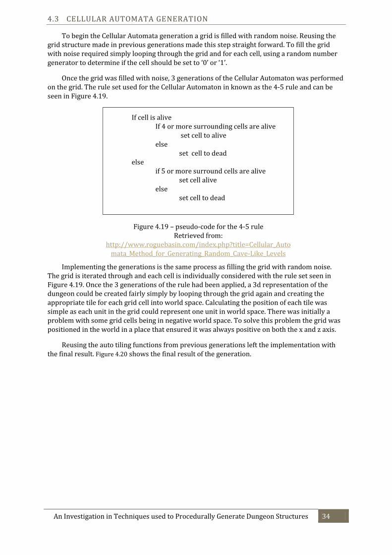
To begin the Cellular Automata generation a grid is filled with random noise. Reusing the grid structure made in previous generations made this step straight forward. To fill the grid with noise required simply looping through the grid and for each cell, using a random number generator to determine if the cell should be set to ‘0’ or ‘1’.
Once the grid was filled with noise, 3 generations of the Cellular Automaton was performed on the grid. The rule set used for the Cellular Automaton in known as the 4-5 rule and can be seen in Figure 4.19.
Implementing the generations is the same process as filling the grid with random noise. The grid is iterated through and each cell is individually considered with the rule set seen in Figure 4.19. Once the 3 generations of the rule had been applied, a 3d representation of the dungeon could be created fairly simply by looping through the grid again and creating the appropriate tile for each grid cell into world space. Calculating the position of each tile was simple as each unit in the grid could represent one unit in world space. There was initially a problem with some grid cells being in negative world space. To solve this problem the grid was positioned in the world in a place that ensured it was always positive on both the x and z axis.
Reusing the auto tiling functions from previous generations left the implementation with the final result. Figure 4.20 shows the final result of the generation.
If cell is alive If 4 or more surrounding cells are alive set cell to alive else set cell to dead else if 5 or more surround cells are alive set cell alive else set cell to dead
Figure 4.19 – pseudo-code for the 4-5 rule Retrieved from:
http://www.roguebasin.com/index.php?title=Cellular_Automata_Method_for_Generating_Random_Cave-Like_Levels

An Investigation in Techniques used to Procedurally Generate Dungeon Structures 35
Several different rule sets for the Cellular Automaton were experimented with during the development of the generation, however non produced ideal results except for the 4-5 rule, as such this rule was decided on to be used for the final implementation. This could suggest an explanation why very little literature was found on the use of Cellular Automata for use in level generation passed cavern structures in the background research, due to it being difficult to control the out of the technique in a meaningful way.
Figure 4.20 – Screenshot of outputted structured of Cellular Automata generation

An Investigation in Techniques used to Procedurally Generate Dungeon Structures 36
5 TEST EVALUATION
The created prototype generations will be evaluated using the evaluation strategy outline in section 3.3. The three primary evaluation categories will be used to conduct the evaluation as well as one secondary evaluation strategy.
5.1 IS THE STRUCTURE A DUNGEON?
In section 3.3.1 three criteria were identified that would be used to determine if generated structures were valid to be accepted as a dungeons The output of the implemented generations will be considered and determine if they meet the requirements outlined. Figure 5.1 shows the results of each generation judged against the outlined requirements.
Figure 5.1 – Grid of generation types compared against dungeon criteria
As is shown in Figure 5.1 both the Delaunay and BSP generation satisfies the criteria for being considered a dungeon. However the Cellular Automata generation fails as it does not produce rooms in the generation, and not all areas of the generation are fully connected together, i.e. there are areas that are impossible to get to inside the structure.
5.2 IMPLEMENTATION DIFFICULTY
To estimate the difficulty of the implementation of different techniques, several criteria will be considered from the experience gained during the development of the prototypes. By considering these criteria, a personal estimate rating will be given to each technique to represent the difficulty of the implementation.
Generation Type Implementation
time (hours) Debugging time
(hours) Total Difficulty
rating (1-5*) Delaunay 60 10 4
BSP 20 3 3 Cellular Automata 3 0.2 1
Figure 5.2 – Grid of generation types compared to difficulty criteria
*1 the implementation was very straightforward, not very challenging. 5 the difficult was extremely difficult, many challenging problems encountered.
Figure 5.2 demonstrates that the Delaunay generation was the most challenging to implement, taking roughly 3x the time as the BSP generation, and required the most amount of time to debug. The BSP generation was moderately difficult, but did not require as much relative time to find problems with the generation. The Cellular Automata generation was significantly less time consuming to implement that the other two generation techniques and required far less time to debug.
Generation Type Are there clearly definable rooms in the structure?
Do rooms overlap with one another?
Are all rooms fully
connected to the Dungeon?
Does the structure
qualify as a Dungeon?
Delaunay Yes No Yes Yes BSP Yes No Yes Yes
Cellular Automata No No No No

An Investigation in Techniques used to Procedurally Generate Dungeon Structures 37
0
1
2
3
4
5
6
7
8
2 4 8 16 32 64 128
Tim
e (
S)
Number of Rooms
Delaunay Generation Time
5.3 GENERATION TIME
The Generation time of the implementation is measured using a built in function to Unity named ‘Time.realtimeSinceStartup’. The function is described in the Unity Documentation as “The real time in seconds since the game started (Read Only)” (Unity Technologies, 2014). For the Delaunay and BSP generation a consistent sample size of room numbers was used to try and give a fair comparison. The generations were measured 5 times for each different room count and the results averaged out to get the final value.
5.3.1 DELAUNAY GENERATION
The full data used to construct the graph in Figure 5.3 can be seen in Appendix B.
The results of the generation time tests as seen in Figure 5.3 do not yield anything unexpected. As more rooms are generated in the dungeon the generation time takes longer. 128 rooms was the largest to the power of 2 test that could be completed, as the results show in Appendix B, the program crashed when trying any room number of 265 or greater. The results suggest here that the generation length is largely linked to the number of rooms generated, and could become substantially long if a large number of rooms are used.
Figure 5.3 – Graph of Delaunay generation time with different room amounts

An Investigation in Techniques used to Procedurally Generate Dungeon Structures 38
0
0.5
1
1.5
2
2.5
3
3.5
4
2 4 8 16 32 64 128 256
Tim
e (
S)
Number of Rooms
BSP Generation Time
5.3.2 BSP GENERATION
The full data used to construct the graph in Figure 5.4 can be seen in Appendix C.
The results of the generation time test shown in Figure 5.4 produced some interesting and unexpected results. As more rooms are generated, up to around 64 rooms, the generation time actually decreases, then after 64 rooms starts to rise again. There are some possible explanations for this behaviour. Because in the BSP generation the size of the dungeon space stays consistent, regardless of room numbers generated, this means with only 1 split of the BSP tree, you end up with two very large rooms that cover the entire dungeon space. Tiling these rooms will require far more walls than would be present in a dungeon with more splits, as there is less empty space between rooms in the dungeon. As such, as you add more splits, you actually add more empty space (because of the padding between partitions when adding rooms). This could suggest why less splits take longer to generate. However a dungeon with 256 rooms takes around 1.5 seconds to generate, giving this generation method a fast execution time in large dungeons, but performs slow in small dungeons.
Figure 5.4 – Graph of BSP generation time with different room amounts

An Investigation in Techniques used to Procedurally Generate Dungeon Structures 39
0
0.5
1
1.5
2
2.5
3
2500 5625 10000 15625 22500 30625 40000
Tim
e (
S)
Number of Cells in Grid
Cellular Automata Generation Time
5.3.3 CELLULAR AUTOMATA GENERATION
The full data used to construct the graph in Figure 5.4 can be seen in Appendix D. Due to the way the Cellular Automata generation works it was not possible to measure generation time against number of rooms in the dungeon, as there are no defined rooms in the dungeon. As such the generation time was measured against the size of the grid used to store the dungeon.
The graph in Figure 5.5 shows that as the grid gets larger the time it takes to generate the dungeon takes longer. There is some level off of the increase in time around a grid size of 20,000 to 30,000. The reason for this level off is unclear. However a generalized observation can be made that as more cells are added to the dungeon, the longer it takes to generate. The largest test shows a 2.5 second generation time, which would in most cases, probably be satisfactory in the use of a game.
Figure 5.5 - Graph of Cellular Automata generation time with different grid sizes
An Investigation in Techniques used to Procedurally Generate Dungeon Structures 40
0
1
2
3
4
5
6
7
8
2 4 8 16 32 64 128 256
Tim
e (
S)
Number of Rooms
Generation Time Comparison
BSP Generation Time
Delaunay Generation Time
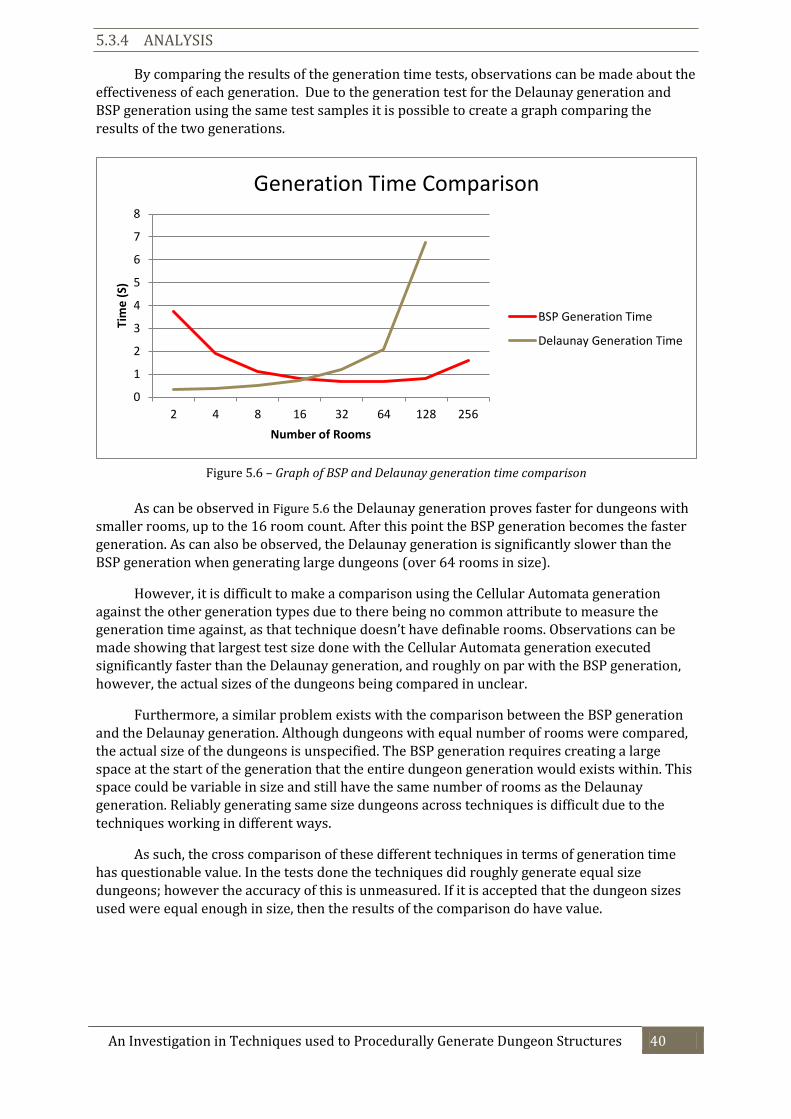
5.3.4 ANALYSIS
By comparing the results of the generation time tests, observations can be made about the effectiveness of each generation. Due to the generation test for the Delaunay generation and BSP generation using the same test samples it is possible to create a graph comparing the results of the two generations.
As can be observed in Figure 5.6 the Delaunay generation proves faster for dungeons with smaller rooms, up to the 16 room count. After this point the BSP generation becomes the faster generation. As can also be observed, the Delaunay generation is significantly slower than the BSP generation when generating large dungeons (over 64 rooms in size).
However, it is difficult to make a comparison using the Cellular Automata generation against the other generation types due to there being no common attribute to measure the generation time against, as that technique doesn’t have definable rooms. Observations can be made showing that largest test size done with the Cellular Automata generation executed significantly faster than the Delaunay generation, and roughly on par with the BSP generation, however, the actual sizes of the dungeons being compared in unclear.
Furthermore, a similar problem exists with the comparison between the BSP generation and the Delaunay generation. Although dungeons with equal number of rooms were compared, the actual size of the dungeons is unspecified. The BSP generation requires creating a large space at the start of the generation that the entire dungeon generation would exists within. This space could be variable in size and still have the same number of rooms as the Delaunay generation. Reliably generating same size dungeons across techniques is difficult due to the techniques working in different ways.
As such, the cross comparison of these different techniques in terms of generation time has questionable value. In the tests done the techniques did roughly generate equal size dungeons; however the accuracy of this is unmeasured. If it is accepted that the dungeon sizes used were equal enough in size, then the results of the comparison do have value.
Figure 5.6 – Graph of BSP and Delaunay generation time comparison

An Investigation in Techniques used to Procedurally Generate Dungeon Structures 41
5.4 MEMORY USAGE
The memory usage of each implementation was measured using the Unity Pro Profiler, which gives access to statistics on the programs execution such as total memory used. Rendering was disabled during the tests so that the memory usage was not increased by rendering.
5.4.1 DELAUNAY GENERATION
The full data used to construct the graph in Figure 5.7 can be seen in Appendix E.
Figure 5.7 - Graph of Delaunay RAM usage with different room amounts
Similar to the results observed in the generation time for the Delaunay generation, as larger dungeons are generated more RAM is used to store the dungeon. This would be expected due to the generation adding in more rooms that are not otherwise present in dungeons with smaller room counts. Each room would have to be stored in memory which would account for the increase in RAM usage.
0
50
100
150
200
250
2 4 8 16 32 64 128
RA
M (
M.B
)
Number of Rooms
Delaunay RAM Usage

An Investigation in Techniques used to Procedurally Generate Dungeon Structures 42
5.4.2 BSP GENERATION
The full data used to construct the graph in Figure 5.8 can be seen in Appendix F.
Figure 5.8 - Graph of BSP RAM usage with different room amounts
The results from the BSP RAM usage tests are fairly interesting, but when considered, are quite logical. As can be seen in Figure 5.8 the difference in RAM usage from the smallest dungeon to the largest is relatively small, only having a difference of about 15mb. The RAM usage goes up very little when more rooms are generated, in most cases. When considering how the technique works, this can be explained. The generation method creates one large area for the dungeon, and then split it up more and more depending on how many rooms are required. Because of this the dungeon size is the same if there are 2 rooms, or if there are 256 rooms. The only attribute that changes is how many segments the dungeon is broken into between the different room counts. As the dungeon isn’t getting larger as rooms are added it is logical than the RAM usage stays roughly the same. The small increase in RAM that is seen can be possibly related to there being more tiles in dungeons with higher room counts.
55
60
65
70
75
80
2 4 8 16 32 64 128 256
RA
M (
M.B
)
Number of Rooms
BSP RAM Usage

An Investigation in Techniques used to Procedurally Generate Dungeon Structures 43
5.4.3 CELLULAR AUTOMATA GENERATION
The full data used to construct the graph in Figure 5.9 can be seen in Appendix G.
Figure 5.9 – Graph of Cellular Automata RAM Usage with different grid sizes
The results of the Cellular Automata RAM tests as seen in Figure 5.9 do not yield anything unexpected. As the number of cell in the grid increases, so does the RAM usage of the dungeon. The increase is consistent across all data points. This would be expected as larger size grids are created for larger dungeons, and as the grid gets larger, more RAM would be required to store it.
0
50
100
150
200
250
300
2500 5625 10000 15625 22500 30625 40000
RA
M (
M.B
)
Number of Cells in Grid
Cellular Automata RAM Usage

An Investigation in Techniques used to Procedurally Generate Dungeon Structures 44
5.4.4 ANALYSIS
The RAM usage tests have the same potential problem as discussed in section 5.3.4, due to the potential different sizes of the dungeons. However, as mentioned before, effort was put in to ensure the dungeons were roughly the same size, as far as was possible to achieve.
Figure 5.10 shows the comparison between the Delaunay and BSP generations RAM usage test results.
Figure 5.10 - Graph of BSP and Delaunay RAM usage comparison
As can be seen in Figure 5.10 the BSP generation uses less RAM than the Delaunay generation in all test samples. This would suggest that BSP is a more efficient method in terms of memory consumption. However, the RAM usage is fairly similar up to around the 32 room generations, and it is only after that point in which the Delaunay generation starts using significant more RAM.
The Cellular Automata results are harder to compare with the other generations again because of the lack of consistent sample data to compare against. It can be observed than the RAM usage of the generation starts around roughly the same amount as the other generations and the largest test sample is slightly larger than the largest Delaunay generation test sample.
0
50
100
150
200
250
2 4 8 16 32 64 128
RA
M (
M.B
)
Number of Rooms
RAM Usage Comparison
Delaunay
BSP

An Investigation in Techniques used to Procedurally Generate Dungeon Structures 45
5.5 PRODUCT SWOT ANALYSIS
To assess the value of the produced product an S.W.O.T analysis will be undertaken to identify key characteristics of the product. Doing an S.W.O.T analysis helps “maximizes the potential of the strengths and opportunities while minimizing the impact of the weakness and threats” (ERC, 1998) of the evaluated software.
5.5.1 STRENGTHS
The key strengths to the product are:
Three unique generation techniques were implemented and tested
New room connection strategy was created (Transitive connect strategy).
Data was collected and analysed from each unique generation technique.
Cross comparisons and conclusions were drawn from collected data
5.5.2 WEAKNESSES
Evaluations did not use consistent metrics across all generations
Data was only collected on one set of hardware
1 of the 3 techniques did not produce a structure that qualified as a dungeon
5.5.3 OPPORTUNITIES
More research areas have been identified through the project that could be further investigated, such as Graph Grammars and Shape Grammars.
5.5.4 THREATS
Produced structures were not analysed from a level design perspective. Only analytically against hard metrics.
The analysis of the product highlights that there are several strong points to the product however the weakness shows that some of the strengths may not be as full proof as they seem at first look when examined more closely. However, the product does meet the requirements initially set out when the investigation began. All primary evaluation strategies were applied to created generations and results were obtained as to the evaluation strategy stated in section 3.3.
The threats highlight how even though generations were created and evaluated, at no point a design perspective was considered on the created generations. Due to this it is potentially possible that the created generations have no practical use in actual games development. This is potentially a large issue with the investigation as the object was to investigate techniques more thoroughly in the hope to help game developers make informed choices on which technique to use in their projects. If the techniques aren’t useable in a games development, the results found during the evaluation will have little value to game developers.
However, it is unlikely this is the scenario, as there are examples of such techniques already being used in commercial projects. For example, TinyKeep (PhiGames, 2014) uses the Delaunay technique for its dungeon generation and Pixel Dungeon (Watabou, 2014) uses a BSP method for its dungeon generation, suggesting at least these two techniques are applicable for use in games development.
An Investigation in Techniques used to Procedurally Generate Dungeon Structures 46
6 CONCLUSION
6.1 PROJECT EVALUATION
The success of the project was outlined in section 3.3.2 to be linked to two main factors. The first being the number of successful generation techniques that were implemented. Through the development of the product three different techniques were implemented out of four that were identified in section 2.3. As such, in regards to the first factor, the product was comprehensive, and met the requirements set out for the project. More work could be done by doing an implementation of a generation technique based around Graph Grammars. This was not completed during this project due to the complexity of the technique. It was analysed as a threat to the project to try and undertake the work required to complete the implementation. Judging by the experience gained implementing and evaluating the first three techniques, this choice proved to be a beneficial one to the project.
The second factor linked to the success of the project was determined as the completion of the evaluations of the generations. All created generations were evaluated using the primary criteria determined in section 3.3.1. One secondary criterion was evaluated as well. As such, the evaluation of the generations was largely comprehensive. The integrity of the evaluation strategies was questioned, and potential problems were identified. There are further metrics that could be evaluated from the secondary evaluation criteria, leaving room for further work in the area. As discovered during the evaluations of each generation, it was found to be difficult to accurately measure any metric across different generations, due to the non-uniformed size of each dungeon. It was has been learnt through undertaking this process that creating test strategies can be difficult, and much attention has to be considered to unifying and formalizing the testing strategy’s.
The time management of the project compared to the expected timetables created during the initial stages of the project as can be seen in Appendix H and Appendix I, has varied fairly significantly. Some of the main reasons for this variation were a large misunderstanding of how long the initial research would take, compared to how long it took in reality. Having never researched any topic in as much depth as this report covers, it is understandable that the prediction was incorrect. This report has help bring awareness to how long research takes and the knowledge learnt will help with the planning of future projects.
6.2 FURTHER RESEARCH
Several areas of the investigating undertaken have either lead to new topics that were not possible to research in the time frame of this investigation or demonstrated weakness in the approach that was taken.
Further research into Graph Grammar and Shape Grammar based dungeon generation would be largely beneficial for the investigation. The initial background research demonstrates large amounts of potential for the technique, especially related to generating dungeons around level design requirements. The research into this topic would relate to another area that needs further work from the evaluation strategies. Evaluating the potential use a dungeon has in terms of game design and level design is needed. Learning new approaches on how to accurately test different generation techniques with different metrics, such as metrics related to the level design feasibility of a generated dungeon, would be beneficial. This area would also help avoid the problems encountered with the evaluation strategies used in this evaluation, where the compared data wasn’t completely consistent.

An Investigation in Techniques used to Procedurally Generate Dungeon Structures 47
These are the main areas of further research that have been identified through doing this investigation. The investigation itself could be broaden by looking at different types of dungeon generations, such as for levels with side on perspective instead of top down/3D.
6.3 PROJECT CONCLUSION
There have been many successes achieved during the completion of this project. The main success is the implementation of the different algorithms. The Delaunay one was particularly challenging and many new programming related techniques were learnt through the process of completing the implementation, such as how triangulation works, its purpose, and many different problems calculating triangulations can help solve, such as finding a convex hull of a group of polygons.
Some areas of the project have been less successful, even some areas related to the implementations of the generation techniques. For example, no proper use of Software Quality Assurance (SQA) was applied during the development of the prototypes, leaving potentially lower quality demo’s than would of otherwise been created with the use of SQA. Other less successful areas have been outline in previous sections, such as the problems found with the evaluation strategy.
However, the entire project has been a great learning experience, and the areas that were less successful were the most useful to learn from. The project has successfully achieved the goals it set out to achieve, to at least a satisfactory level. The conclusions drawn from the evaluation strategy, although possibly not precisely accurate, do show how the different generations work from a high level perspective, for example, the BSP tree will always only require roughly as much memory as the first split requires, whereas the Delaunay dramatically increases in memory consumption as more rooms are added. Information such as this, derived from the evaluation strategy, can be useful for a game developer to know when trying to choose a technique for their game. As the focus of the report, was to help game developers make more informed decisions on techniques to use, the results found in this report can indeed help them do that.
Dungeon generation is a very broad and complex area of PCG. This project has helped further the formalization of the subject, and scratched the very surface of an otherwise deep and ever increasing area of computer games development. The future for the topic is exciting and only just beginning.

An Investigation in Techniques used to Procedurally Generate Dungeon Structures 48
7 APPENDIX
7.1 APPENDIX A – DUNGEON TILESET
A render of the tiles used in the tile set all three dungeon generations used, as retrieved from http://opengameart.org/content/3d-dungeon-tileset (08/03/2014) Special thanks to OpenGameArt.org member ‘Skorpio’ for making this tile set freely available to be used and Liam Bower for exporting the individual models

An Investigation in Techniques used to Procedurally Generate Dungeon Structures 49
7.2 APPENDIX B – DELAUNAY GENERATION TIME RESULTS
Test Number Number of Rooms Generation Time (S) 1 2 0.3394571 2 2 0.3045621 3 2 0.3647743 4 2 0.3073522 5 2 0.3528039
Average Time: 0.33378992
Test Number Number of Rooms Generation Time (S) 1 4 0.4056896 2 4 0.403481 3 4 0.3748098 4 4 0.3676056 5 4 0.3530588
Average Time: 0.38092896
Test Number Number of Rooms Generation Time (S) 1 8 0.4904901 2 8 0.4970773 3 8 0.566237 4 8 0.4703249 5 8 0.5374306
Average Time: 0.51231198
Test Number Number of Rooms Generation Time (S) 1 16 0.7454771 2 16 0.6809146 3 16 0.6903022 4 16 0.7244036 5 16 0.714299
Average Time: 0.7110793
Test Number Number of Rooms Generation Time (S) 1 32 1.18694 2 32 1.231536 3 32 1.225295 4 32 1.181989 5 32 1.156056
Average Time: 1.1963632
Test Number Number of Rooms Generation Time (S) 1 64 2.103427 2 64 2.008343 3 64 2.09196 4 64 2.09456 5 64 2.107467
Average Time: 2.0811514

An Investigation in Techniques used to Procedurally Generate Dungeon Structures 50
*Program crashed when trying to execute test
Test Number Number of Rooms Generation Time (S) 1 128 6.702223 2 128 6.406401 3 128 6.930064 4 128 7.070667 5 128 6.594977
Average Time: 6.7408664
Test Number Number of Rooms Generation Time (S) 1 256 N/A* 2 256 N/A* 3 256 N/A* 4 256 N/A* 5 256 N/A*
Average Time: N/A*

An Investigation in Techniques used to Procedurally Generate Dungeon Structures 51
7.3 APPENDIX C – BSP GENERATION TIME RESULTS
Test Number Number of BSP Splits Number of Rooms Generation Time (S) 1 1 2 4.011813 2 1 2 3.647554 3 1 2 3.642833 4 1 2 3.790057 5 1 2 3.6146
Average Time: 3.7413714
Test Number Number of BSP Splits Number of Rooms Generation Time (S) 1 2 4 1.94444 2 2 4 1.967834 3 2 4 1.845763 4 2 4 1.911388 5 2 4 1.893493
Average Time: 1.9125836
Test Number Number of BSP Splits Number of Rooms Generation Time (S) 1 3 8 1.132471 2 3 8 1.126262 3 3 8 1.108531 4 3 8 1.127339 5 3 8 1.171568
Average Time: 1.1332342
Test Number Number of BSP Splits Number of Rooms Generation Time (S) 1 4 16 0.8044382 2 4 16 0.8281473 3 4 16 0.8192808 4 4 16 0.8231851 5 4 16 0.8345353
Average Time: 0.82191734
Test Number Number of BSP Splits Number of Rooms Generation Time (S) 1 5 32 0.7047508 2 5 32 0.7018908 3 5 32 0.6938654 4 5 32 0.7016528 5 5 32 0.6939383
Average Time: 0.69921962

An Investigation in Techniques used to Procedurally Generate Dungeon Structures 52
Test Number Number of BSP Splits Number of Rooms Generation Time (S) 1 6 64 0.6918635 2 6 64 0.6915058 3 6 64 0.677397 4 6 64 0.6931908 5 6 64 0.6945659
Average Time: 0.6897046
Test Number Number of BSP Splits Number of Rooms Generation Time (S) 1 7 128 0.8196436 2 7 128 0.8137906 3 7 128 0.8209357 4 7 128 0.8082628 5 7 128 0.827222
Average Time: 0.81797094
Test Number Number of BSP Splits Number of Rooms Generation Time (S) 1 8 256 1.576295 2 8 256 1.603643 3 8 256 1.605789 4 8 256 1.584035 5 8 256 1.610196
Average Time: 1.5959916
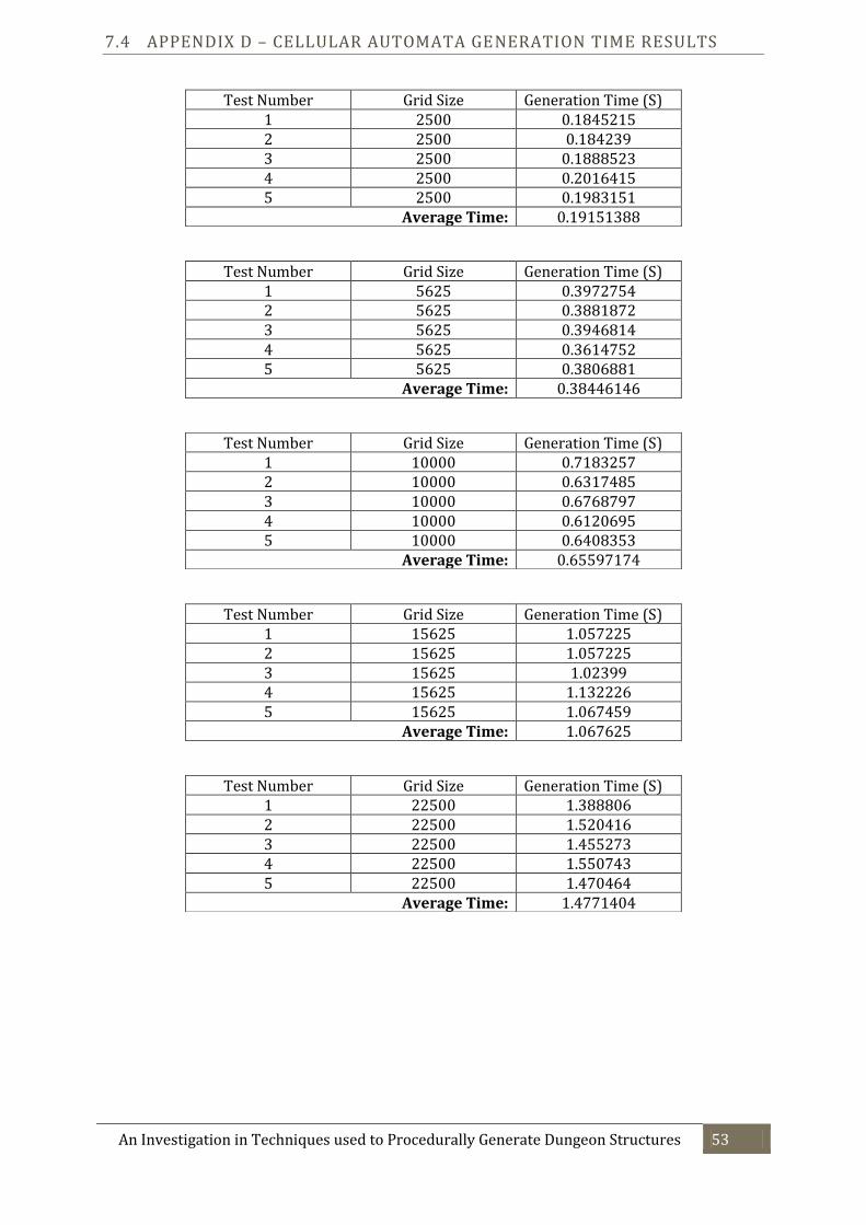
An Investigation in Techniques used to Procedurally Generate Dungeon Structures 53
7.4 APPENDIX D – CELLULAR AUTOMATA GENERATION TIME RESULTS
Test Number Grid Size Generation Time (S) 1 2500 0.1845215 2 2500 0.184239 3 2500 0.1888523 4 2500 0.2016415 5 2500 0.1983151
Average Time: 0.19151388
Test Number Grid Size Generation Time (S) 1 5625 0.3972754 2 5625 0.3881872 3 5625 0.3946814 4 5625 0.3614752 5 5625 0.3806881
Average Time: 0.38446146
Test Number Grid Size Generation Time (S) 1 10000 0.7183257 2 10000 0.6317485 3 10000 0.6768797 4 10000 0.6120695 5 10000 0.6408353
Average Time: 0.65597174
Test Number Grid Size Generation Time (S) 1 15625 1.057225 2 15625 1.057225 3 15625 1.02399 4 15625 1.132226 5 15625 1.067459
Average Time: 1.067625
Test Number Grid Size Generation Time (S) 1 22500 1.388806 2 22500 1.520416 3 22500 1.455273 4 22500 1.550743 5 22500 1.470464
Average Time: 1.4771404

An Investigation in Techniques used to Procedurally Generate Dungeon Structures 54
Test Number Grid Size Generation Time (S) 1 30625 1.52603 2 30625 1.531386 3 30625 1.583579 4 30625 1.465613 5 30625 1.551985
Average Time: 1.5317186
Test Number Grid Size Generation Time (S) 1 40000 2.689693 2 40000 2.694524 3 40000 2.742126 4 40000 2.818364 5 40000 2.59924
Average Time: 2.7087894

An Investigation in Techniques used to Procedurally Generate Dungeon Structures 55
7.5 APPENDIX E – DELAUNAY GENERATION MEMORY RESULTS
* Program crashed when trying to execute test
7.6 APPENDIX F – BSP GENERATION MEMORY RESULTS
7.7 APPENDIX G – CELLULAR AUTOMATA GENERATION MEMORY RESULTS
Test Number Number of Rooms R.A.M Usage (~MB) 1 2 82 2 4 85 3 8 88 4 16 97 5 32 98 6 64 129
7 128 204
8 256 N/A*
Test Number Number of BSP Splits Number of Rooms R.A.M Usage (~MB) 1 1 2 65 2 2 4 68 3 3 8 68 4 4 16 69 5 5 32 69 6 6 64 70
7 7 128 74
8 8 256 78
Test Number Grid Size R.A.M Usage (~MB) 1 2500 66 2 5625 73 3 10000 93 4 15625 128 5 22500 152 6 30625 192
7 40000 248

An Investigation in Techniques used to Procedurally Generate Dungeon Structures 56
7.8 APPENDIX H – FIRST TERM DEVELOPMENT TIMETABLE
.
Week Commencing
Task 17/11/2013 24/11/2013 01/12/2013 08/12/2013 15/12/2013 22/12/2013 29/12/2013 05/01/2013 12/01/2013
Interview users for requirements
Look for research material
Develop Evaluation Strategy
Begin write up of initial research
Create Initial Test Strategy
Prototype Initial Generation Methods Reflected on initial findings and approach

An Investigation in Techniques used to Procedurally Generate Dungeon Structures 57
7.9 APPENDIX I – SECOND TERM DEVELOPMENT TIMETABLE
The time allocated to this project has been broken down into weeks, with each week assigned a task that needs to be completed during the week. Two weeks have been given to allow for the work load from other modules around hand in times and one week is reserved for either working on secondary evaluations if the project is running smoothly or catching up on past tasks that may not have been completed during their designated slot.
Task 01/02/2014 08/02/2014 15/02/2014 22/02/2014 01/03/2014 08/03/2014 15/03/2014 22/03/2014
Finish background research BSP Implementation
TinyKeep implementation
Shape Grammar implementation
Task 29/03/2014 01/04/2014 08/04/2014 15/04/2014 22/04/2014 29/04/2014 01/05/2014
Other module hand ins
Primary Evaluation
Secoundary Evaluation/Recovery
Final write up / Conclusion

An Investigation in Techniques used to Procedurally Generate Dungeon Structures 58
8 BIBLIOGRAPHY
Adams, D. (2002). Automatic Generation of Dungeons for Computer Games. University of Sheffield. Retrieved from: http://www.dcs.shef.ac.uk/intranet/teaching/public/projects/archive/ug2002/pdf/u9da.pdf Angry Fish Studios. (2011). Bitmasking Infographic [web log post]. Retrieve from: http://www.angryfishstudios.com/2011/04/adventures-in-bitmasking/ Barton, M. Loguidice, B. (2009, May, 05). Gamasutra - The History of Rogue: Have @ You, You Deadly Zs. Retrieved from: http://www.gamasutra.com/view/feature/132404/the_history_of_rogue_have__you_.php?page=2 Basic Dungeon Generation. (2012, October, 26). Retrieved from: http://roguebasin.roguelikedevelopment.org/index.php?title=Basic_BSP_Dungeon_generation Berg, Mark de (2010). Computational geometry: algorithms and applications (3rd edition). Springer: Berlin. ISBN: 9783540779742 Cube Roots. (2014). Dungeon Hearts 2 [Computer Software]. Cube Roots. (2014). Dungeon Hearts 2 Independent Gaming Source topic. Retrieved from: http://forums.tigsource.com/index.php?topic=35116.0 Dinh, P. (2013). Procedural Dungeon Generation Algorithm Explaines. Retrieved from: http://www.reddit.com/r/gamedev/comments/1dlwc4/procedural_dungeon_generation_algorithm_explained/ Driver, S. (2010). A Bitwise Method For Applying Tilemaps [web log post]. Retrieved from: http://www.saltgames.com/2010/a-bitwise-method-for-applying-tilemaps/ Discord Games. (2014). Chasm [Computer Software] Discord Games. (2014). Chasm Independent Gaming Source topic. Retrieved from: http://forums.tigsource.com/index.php?topic=30117.0 Discord Games. (2014). Official website. Retried from: http://www.chasmgame.com/ Dormans, J. (2010) Adventures in level design: Generating missions and spaces for action adventure games. Retrieved from: http://www.jorisdormans.nl/pdf/dormans2010_AdventuresInLevelDesign.pdf Dormans, J. Bakkes, S. (2011). Generating Missions and Spaces for Adaptable Play Experiences. IEE Transactions on Computational Intelligence and AI in Games. volume 3. Retrieved from: http://sander.landofsand.com/publications/Dormans_Bakkes_-_Generating_Missions_and_Spaces_for_Adaptable_Play_Experiences.pdf ERC (1998). SWOT Analysis. Retrieved from: http://erc.msh.org/quality/ittools/itswot.cfm

An Investigation in Techniques used to Procedurally Generate Dungeon Structures 59
Firemana. (2013). Stack Overflow answer [web log post]. Retrieved from: http://stackoverflow.com/a/16909956 Fuchs, H. (1980). On visible surface generation by a priori tree structures. 124-133. Retrieved from: http://dl.acm.org/citation.cfm?id=807481 Gärtner, B. (N.D). Delaunay Triangulation: Incremental Construction. Retrieved from: http://www.ti.inf.ethz.ch/ew/courses/CG13/lecture/Chapter%207.pdf Gearbox Software. [gearboxsoftware]. (2013, August, 31). Borderlands 2: An Introduction by Sir Hammerlock. Retrieved from: http://www.youtube.com/watch?v=oUu-FzRFYZA Infolet.org. (N.D). Find Area of Rectangle, Triangle and Circle in C#. Retrieved from: http://www.infolet.org/2012/11/calculate-area-of-rectangle-triangle-circle-in-c.html Johnson, L. Yannakakis, G.N. Togelius, J. (2010). Cellular automata for real-time generation of infinite cave levels. Retrieved from: http://www.itu.dk/people/yannakakis/a7-Johnson.pdf Kushner, D. (2003). Masters of Doom. United States, Random House, Inc. Lawson, C.L. (1972). Transforming Triangulations. Pages 365-372. Retrieved from: http://www.diku.dk/hjemmesider/ansatte/rfonseca/literature/lawson/index.html Linden, R.V.D. Lopes, R. Bidarra, R. (2013). Designing Procedurally Generated Levels. Retrieved from: http://graphics.tudelft.nl/~rafa/myPapers/bidarra.RvdL.IDP13.pdf Millington, I. Funge, J. (2009). Artificial Intelligence for Games. (2nd edition).Massachusetts: Elsevier. ISBN: 978-0-12-374731-0 Mossmouth. (2013). Spelunky [Computer Software]. Naughtyyt (03/04/2013) Graph Grammar based Procedural Generation for a Rougelike [Video File]. Retrieved from: http://www.youtube.com/watch?v=RAtdFKiqs34&feature=youtu.be Naughty (2013) Graph Grammar and Voronoi based Level Generation for a Roulgelike – Work in Progress. Retrieved from: http://www.reddit.com/r/gamedev/comments/1bne5o/graph_grammar_and_voronoi_based_level_generation/ Persson, M. (2010, March, 02). Clearing up the world size math. [Web log post]. Retrieved from: http://notch.tumblr.com/post/422515389/clearing-up-the-world-size-math Phigames (2013). TinyKeep - A 3D Dungeon Crawler. Retrieved from: http://tinykeep.com PhiGames. (2014). Tiny Keep [Computer Software]. Prim, R.C. (1957). Shortest Connection Networks And Some Generalizations. Retrieved from: http://www3.alcatel-lucent.com/bstj/vol36-1957/articles/bstj36-6-1389.pdf Quendus (2014/04/04) Re: Graph Grammar and Voronoi based Dungeon Generation [web log post]. Retrieved from: http://forums.roguetemple.com/index.php?PHPSESSID=e3ss1jbg8rm4khb2dja9qg2ma4&topic=3222.msg26626#msg26626

An Investigation in Techniques used to Procedurally Generate Dungeon Structures 60
Reynolds, C (2004). Steering Behaviors For Autonomous Characters. Retrieved from: http://www.red3d.com/cwr/steer/ Scott, J. (N.D). Point in triangle test. Retrieved from: http://www.blackpawn.com/texts/pointinpoly/ Skorpio. (2012). 3D Dungeon Tileset[web log post]. Retrieved from: http://opengameart.org/content/3d-dungeon-tileset Stiny, G. (1978). The Palladian grammar. Environment and Planning B, volume 5, pages 5-18. Retrieved from: https://www.andrew.cmu.edu/course/48-747/subFrames/readings/Stiny&Mitchell.thePalladianGrammar.pdf Toffoli, T. Margolus, N. (1987). Cellular Automata Machines: A New Environment for Modeling. Massachusetts: MIT Press. Togelius, J. Nelson, M.J. Shaker N. (2013). Procedural Content Generation in Games. University of Copenhagen. Retrieved from: http://pcgbook.com/ Toy, M. Wichman, G. Arnold, K. Lane, J. (1980). Rouge [Computer Software]. Unity Technologies. (2014). Unity documentation for Time.realtimeSinceStartup. Retrieved from: https://docs.unity3d.com/Documentation/ScriptReference/Time-realtimeSinceStartup.html USNW Austrillia. (1998). Delaunay Triangulation Algorithms. Retrieved from: http://www.cse.unsw.edu.au/~lambert/java/3d/delaunay.html Velasco, P.P.P (2009) Matrix Graph Grammars as a Model of Computation. Retrieved from: http://arxiv.org/pdf/0905.1202.pdf Watabou. (2014). Pixel Dungeon [Computer Software] Willems, S. (2010) Random Dungeon Generation [Web log post]. Retrieved from: http://www.saschawillems.de/?page_id=395