an investigation of the hydro-electrio possibilities …
TRANSCRIPT

AN INVESTIGATION
OF THE
HYDRO-ELECTRIO POSSIBILITIES FOR FAM POWER
OF A
SMIALL BROOK Ill METHUEII, MASSACHUSETTS.

ci~/ ~Q \ t~s Ile
4
AN ITVESTIGATIOI
OF THE
HYDRO-IECTRIC POSSIBILITIES FOR F1ALM PIOVER
OF A
SIL/JL BROOK IN UETHUEN, MASSACHUSETTS.
A Thesis
Submitted to
The Faculty of the Massachusetts Institute of Technology.
By:
Edwin C. Schatz
Harold L. Townend.

ACKINOWTLIDGE1 E=ETT
Throughout the course of work on this thesis
we have received encouragement, guidance, suggest-
ions and cons:tructive criticism from Prof. Barrows
of the Civil Engineering Department. For the assist-
ance that Prof. Barrows has given us, we wish to thank
him.
7e also wish to thank Mr. Mayo of the S. Morgan
Smith Company, Mr. Garratt of the Remco Wood Stave
Pipe Company, and the General Electric Company for
their advice and quotations.

TABLE OF CONT MTTS
INTRODUCTION. . * . . . . . .
1.IETHOD OF INVESTIGATION . . .
THE DAM . . . . . . . . . . .
THE SPILL'lAY. . . . . . . . .
THE PIPE LINE . . . . . . . .
POWER PLANT.RI?20AIT . . . . ..
EFFICIENCY OF THE UNIIT. . . .
COST OF PLANT. 0 0 0 0
COST OF PO1dER. . . . . . . . . .
RECOMIhENDATIONS. . . . . . .
APPENDICES:
APPENDIX A
APPENDIX B
C
APPENDIX D
APPENDIX E
APPENDIX F
APPENDIX G
APPENDIX H
APPENDIX I
APPENDIX J
APPENDIX K
. . 0 . 0 - *. . Page 1 - 4
. . . 0 . . . . " 5
. . . 0 . . . 0 " 6 -11
. . 0 0 . 0 0 0 " 12 - 14
. ... 15 - 16
. . .. 17 - 21
. . . . 0 . 0 0 "? 22
. 0 . . . . . 0 II 23
. . . 0 . . . . " 24
. 0 . . . . . " 25
Graph (lost head vs Q.)
Efficiency Curve Generator
i " Turbine
Overall Efficiency
Data for Curves
17eir Readings
17iring Diagram
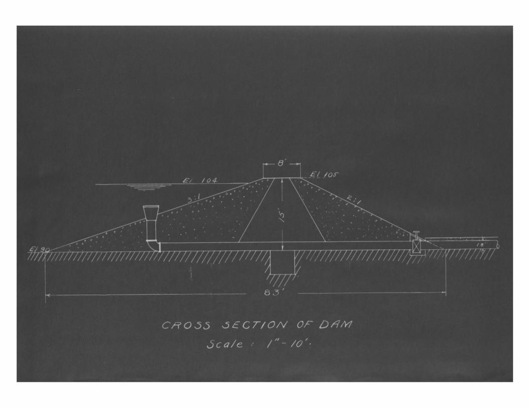
Cross-Section of Dam
Topographical Map
Power House Layout

IrTRODUCTION
The purpose of this paper is to investigate and
report upon the hydro-electric possibilities of a small
brook for farm power.
In recent years the development of hydro-
electric stations has been rapid and of great value to
the country. Most of these stations are of considerable
size, being situated along large rivers. The small de-
velopment has not, on the other hand, received much
attention. This is due to the fact that the power com-
panies are not interested in small units and the individual
owner of a site does not, as a rule, realize the possibil-
ities of the small stream. The State of New York has con-
ducted an investigation along these lines, which speaks
very favorably of the small station, finding that the cost
of maintenance of the plant is very small, the first cost
being in almost every case the controlling factor.
The site investigated for this particular
paper, is in Methuen, Massachusetts, on the farm of Mr.
Richard Batty. The power is to be used, to a very large
extent, for lighting the different farm buildings, and
to run small motors in and about the home.
The source of power is the Bare Meadow Brook,
a small stream with a flow of about one and one-half cu-
bic feet per second. The flow is fairly consistent, as
it is fed by springs. After rains and freshets, the
quantity of water in the brook is considerably larger,
but due to the nature of the drainage area, the peak
values are of short duration.
As the flow is small, storage is necessary.
This is to be accomplished by means of a dam. The most
economical dan proved to be an earthern one, located as
is shown on the map (Appendix J.) Since the material of
which it would be made is rather porous, a loam core is
necessary. The soil for the dam could be taken from the
spillway section and from the hills on either side of the
brook, while the loam can be scraped from the surface of
the ground.
The flooded areas is all pasture land and at
present of very little value, and is practically all in
the property of Mr. Batty.
An additional head of five feet can be obtained by
means of a 225 foot pipe line. The additional cost of in-
stallation of the plant would be more than offset by the
3.
head gained and the more economical use of the water.
The pond would be kept at practically a con-
stant head - not over a foot deviation either way, except
when the demand for power was very urgent. It would not
be feasible to allow the water to drop more than a foot
because the inflow is so small that if the head is once
lowered, it Will require some time to build up again, un-
less the plant were shut down for a considerable period.
The power house will be a small wood-frame
building, containing a vertical reaction turbine, a
generator, governor and switchboard. The wheel will be
a McCormick, 11.4 H.P., 576 R.P.M. vertical set turbine
operating under a 19 foot head. The generator will be
a direct current, compound wound General Electric 7 LN
unit, and would be connected to the turbine with a quarter
turn belt. A Woodward governor will be installed to
operate the wicket gate mechanism.
The entire development will cost about 5,000,
and will cut the cost per K.W.H., the present selling
price by the local power company, of ".125 to .041 at
the switchboard, the saving per year will be approximate-
ly '250.
The cost of the development per horsepower
' 440, is high, as would be expected from so small a plant.
4.0
The cost could be cut dovm considerably if the omer
undertook to build the dam and power house himself, and
this is the logical thing for him to do.
The chances of the plant being shut down, due
to repairs for any long period of time, are very small,
but since it might possibly happen, it would be necessary
to tie in with the power system of Lawrence as a safe-
guard.

5.
LETHOD OF INVESTIGATION.
The amount of water available was de-
termined by weir measurement. A triangular weir
with a 90O notch was erected in the stream for
this purpose. An old dam was utilized in the lo-
cation of the weir. This did not prove entirely
satisfactory, since the water seeped through the
dam to a slight degree. The readings were all a
trifle low for this reason. However, it was de-
cided that the value of 1.5 second feet was a rea-
sonable value to allow for the stream at all times.
The amount of head available was de-
termined by a set of levels. A topographical map
of the site was made by plane table work in the
early part of the summer of 1922, in order to de-
termine the amount of storage and the best location
of the dam.
0.
THE DAM.
In the consideration of this project,
since the governing condition is that of the
available water and the economical utilization
thereof, a means of control is essentially impor-
tant.
The control of the water should be
brought about by means of a storage reservoir.
Due to the character of the topography at this
particular site, this can easily be made by means
of a dam located, as shown on the map.
In order to locate the dam properly,
several factors must be considered. First, utilize
all of the available head; second, allow adequate
storage; third, guard against damage to property
of adjacent owners due to flood conditions at the
high water stage; fourth, a minimum of material;
fifth, a good foundation. These factors must be
balanced, the one against the other, and that solu-
tion determined upon which is most economical.
The foundation should, if possible, be
built upon ledge rock. A careful study of the site

7.
and of the territory surrounding did not disclose any
traces of the presence of ledge rock. In fact, it dis-
closed that the hill over which the brook fell was what
is known as a drumlin, or a hill made up of the drift
deposited by one of the glacial movements from the north.
Therefore, one of the conditions was eliminated in this
project.
The other features are all more closely re-
lated to one another. It was determined by a set of
levels that the top of the dam could not go over a cer-
tain elevation, since this would tend to cause the water
to flood back over the property of the land owner di-
rectly upstream. Obviously, it should be built high
enough so that every foot of head that is available would
be used. It was decided, then, that the top of the dam
would come at elevation 105, in order to meet the two above
named conditions.
Having fixed the elevation of the top, it next
became necessary to determine the location of the dam in
respect to its position on the stream. This must be so
arranged that the water could be stored during the part
of the day that the plant was not in operation. More-
over, it was decided that during this time no water should
be allowed to flow through the spillway. Computations
showed that by placing the dam at the position shown, the
water would not waste over the top under ordinary condi-

8.
tions until storage had been in progress for approxi-
mately twenty hours. Since the plant will normally
be run from eight to ten hours per day, there is suffi-
cient leeway to prevent the waste of water.
This location, however, would not permit the
utilization of all the head available. In order to get
this full head, by means of a dam, its position would
need to be over 200 feet farther downstream. This would
be very uneconomical, since it would necessitate a very
long and rather high dam. Moreover, the increase in the
amount of material in the structure would make it pro-
hibitive. The-ultimate solution, then, was to place
the dam as shown and convey the water through a pipe
line to the power house, 225 feet below the dam. The
site chosen was peculiarly well adapted to the construc-
tion, since at this point the brook is flanked on either
side by high hills, the ravine is narrow and deep; and
by building a dam fifteen feet in height (at the highest
point) it was found that a total head of 19 feet could
be obtained. Fourteen feet of the head would be ob-
tained by the use of the dam, and the other five by the
use of the pipe line.
Several types of dams were considered. The
only practical type was found to be an earth fill dam,
9.
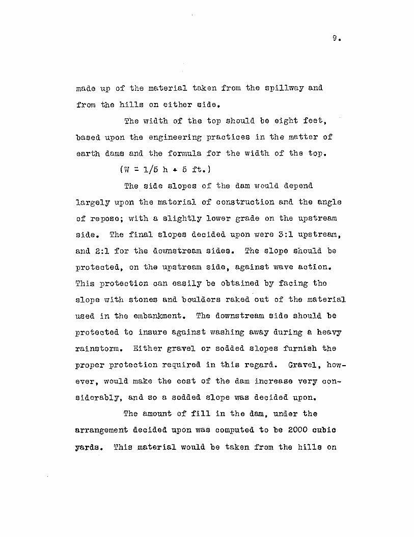
made up of the material taken from the spillway and
from the hills on either side.
The width of the top should be eight feet,
based upon the engineering practices in the matter of
earth dams and the formula for the width of the top.
(71 1/5 h 4 5 ft.)
The side slopes of the dam would depend
largely upon the material of construction and the angle
of repose; with a slightly lower grade on the upstream
side. The final slopes decided upon were 3:1 upstream,
and 2:1 for the dovmstream sides. The slope should be
protected, on the upstream side, against wave action.
This protection can easily be obtained by facing the
slope with stones and boulders raked out of the material
used in the embankment. The downstream side should be
protected to insure against washing away during a heavy
rainstorm. Either gravel or sodded slopes furnish the
proper protection required in this regard. Gravel, how-
ever, would make the cost of the dam increase very con-
siderably, and so a sodded slope was decided upon.
The amount of fill in the dam, under the
arrangement decided upon was computed to be 2000 cubic
yards. This material would be taken from the hills on
10.
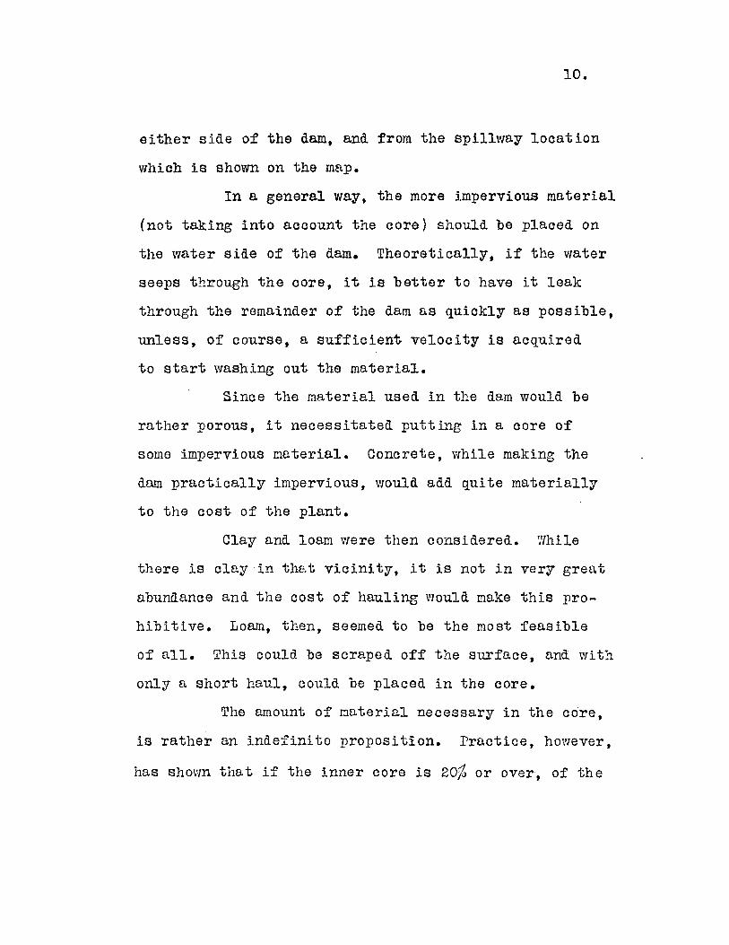
either side of the dam, and from the spillway location
which is shown on the map.
In a general way, the more impervious material
(not taking into account the core) should be placed on
the water side of the dam. Theoretically, if the water
seeps through the core, it is better to have it leak
through the remainder of the dam as quickly as possible,
unless, of course, a sufficient velocity is acquired
to start washing out the material.
Since the material used in the dam would be
rather porous, it necessitated putting in a core of
some impervious material. Concrete, while making the
dam practically impervious, would add quite materially
to the cost of the plant.
Clay and loam were then considered. Yhile
there is clay in that vicinity, it is not in very great
abundance and the cost of hauling would make this pro-
hibitive. Loam, then, seemed to be the most feasible
of all. This could be scraped off the surface, and with
only a short haul, could be placed in the core.
The amount of material necessary in the core,
is rather an indefinite proposition. Practice, however,
has shown that if the inner core is 20O or over, of the
11.
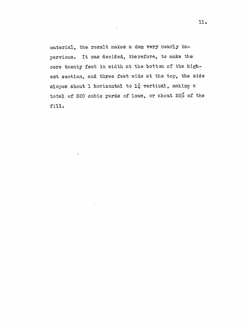
material, the result makes a dam very nearly im-
pervious. It was decided, therefore, to make the
core twenty feet in width at the bottom of the high-
est section, and three feet wide at the top, the side
slopes about 1 horizontal to l-2 vertical, making a
total of 520 cubic yards of loan, or about 25%o of the
fill.

12.
THE SPILLVT;AY
The spillway was designed to carry a
maximum of 200 second feet of water around the dam.
It will have a base width of five feet with sixty
degree side slopes. As the average run-off of this
locality is 1.5 second feet per square mile of drain-
ing area, anl the area drained is but two and a half
square miles, it is readily seen that there is a very
safe margin in the 200 second feet assumption. It
is quite possible that there will never be any demand
for such a large channel. This is due to the flat
drainage area, and the correspondingly slow run-off
tendency, and the existence of several ponds above the
site which would tend to hold in check any sudden
fluctuation in the run-off.
The channel will be surfaced with rock in
order to insure better flow in times of necessity.
The reason for picking such a relatively large section
and lining the channel with rock is that the spillway
is the only means there is of protecting the dam, in
case of an exceptionally heavy and long protracted
rainy spell.
There will be flashboards, two feet high,

placed at the entrance of the spillway. The bottom
of the boards will be at elevation 103, and as the
pond will be at elevation 104, there will be one
foot of water in the channel above the flashboards
on the water side at all times. In order to make
a tight joint, the section of the spillway where the
flashboards are placed will have concrete sides and
bottom. The flashboards will be removable and be
made of one inch spruce timber.
The spillway will be located as shown on
the map, circling the hill on the south side of the
brook. This location was decided upon in order to
insure against the water wasted coming into contact
with the downstream side of the dam. The spillway
could possibly be built nearer the brook and at a
smaller cost, but the risk of damage to the dam would
more than offset the additional cost necessitated by
locating the spillway channel, as shown.
The excavation necessary can all be ac-
complished by scraping, some of the material being
used for the dam and the remainder wasted over the side
of the hill.
The estimated cost of constructing the dam
and spillway, using the excavation of the one for the

14.
fill of the other, is 1200, which can be cut
down quite materially if the owner plans to build
these two portions of the plant himself.

15.
THE PIPE LIIT.
The amount of power that can be developed
by any hydro-electric station is limited by the quan-
tity of water and the available head. The amount of
water which can be used in this project is limited to
approximately 1.5 second feet, and therefore, if a
greater head can be obtained by the use of a pipe line,
it would prove advantageous. It was found that by
using a pipe line 225 feet long, an additional head
of five feet could be obtained.
Numerous types of pipe could be used in
this development. Several kinds of steel and iron
pipes were investigated as well as wood stave pipe.
Steel has a longer life than the wood stave, but it has
the disadvantage of a very large cost, and that it will
corrode.
Wood stave pipe is very suitable for low
head developments and has some advantages over steel,
some of vhich are:- low first cost; it does not cor-
rode; it has a lower coefficient of friction - which
does not become greater with age as in the case of
iron pipes, - and it tends to prevent freezing of the
water, due to the fact that wood is an excellent non-
16.
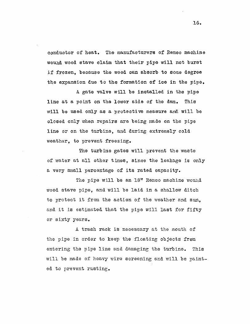
conductor of heat. The manufacturers of Remco machine
woudi wood stave claim that their pipe will not burst
if frozen, because the wood can absorb to some degree
the expansion due to the formation of ice in the pipe.
A gate valve will be installed in the pipe
line at a point on the lower side of the dam. This
will be used only as a protective measure andi will be
closed only when repairs are being made on the pipe
line or on the turbine, and during extremely cold
weather, to prevent freezing.
The turbine gates will prevent the waste
of water at all other times, since the leakage is only
a very small percentage of its rated capacity.
The pipe will be an 18" Remco machine wou.id
wood stave pipe, and will be laid in a shallow ditch
to protect it from the action of the weather and sun,
and it is estimated that the pipe will last for fifty
or sixty years.
A trash rack is necessary at the mouth of
the pipe in order to keep the floating objects from
entering the pipe line and damaging the turbine. This
will be made of heavy wire screening and will be paint-
ed to prevent rusting.
17.
POWER PLANT.
The power house will be a wood frame
structure, 12 feet wide and 16 feet long, set on a
concrete foundation. The house will contain the
turbine, governor, generator, and switchboard.
Two types of turbines are at present in use,
the impulse wheel and the reaction turbine. The im-
pulse wheel is particularly adapted to high head de-
velopments, but must be set at an elevation suffi-
ciently high that a free discharge is obtained.
The vertical reaction turbine is well adapted
for low head developments since it may be operated at
the level of the tail water and thus utilize the entire
head. This type of wheel will also develop a high
specific speed, which is essential in this development.
It was decided to install a vertical re-
action turbine, and because of the small size, it was
necessary to pick a stock size.
Turbines made by the James Leffel Company
and the S. Morgan Smith Company were then investigated
and it was found that the 9 inch McCormick 11.4 H.P.
vertical turbine, manufactured by the S. Morgan Smith
Company, was best suited to the project. This turbine
18.
operates under a 19 foot head, running at 575 R.P.M.
and uses about 6.6 second feet of water.
The turbine will be connected to the gener-
ator by a quarter turn belt. As the rated speeds of
the turbine and generator are not the same, it will
become necessary to use pulleys of different sizes.
The pulley supplied with the turbine is 4 inches wide,
with a 24 inch diameter. The generator will be oper-
ated at 1700 R.P.M., therefore, since the turbine
runs 575 R.P.M., an eight inch pulley will be re-
quired on the generator.
A four inch belt will be used. This size
will easily carry the necessary load. It will be
turned through ninety degrees, since the shaft of the
turbine is vertical, while that of the generator is
horizontal.
The generator to be used is a flat or
slightly over-compounded generator. It is rated
at 7 K.7J; 125 volts, and 1700 R.P.M. The generator
was selected of slightly lower capacity than the
turbine to take account of the belt loss and the
losses in the generator itself.
Direct current will be used as this type
of power is advantageous wherever the transmission
line is short, because it gives better speed regula-
tion with motors, and is as good, or better, than

19.
alternating current for lighting purposes. An in-
duction generator could not be used because there is
no synchronous motor load. A direct current genera-
tor is cheaper than a synchronous generator and re-
quires no exciter. The load center is only about
300 feet from the power house, and so the power loss
in the line will be small.
It is not feasible to generate power at a
higher voltage than 125, because the lighting system
used in this locality is rated at 110 volts and it
may become necessary to use the central station for
standby service.
, The voltage of the load must be kept prac-
tically constant. This is especially necessary in a
lighting load as it is expected to come on this plant,
and a variation of voltage will prove costly for two
important reasons:- a higher voltage causes a de-
crease in the life of the filament, while a lower
voltage means a very decided decrease in the effici-
ency of the lamps.
To maintain a constant- voltage, the speed
must be kept constant. To do this, a Woodward me-
chanical governor is to be installed. A Tirrill vol-
tage regulator could be used, but this apparatus

20.
operates independently of the turbine, and has the
disadvantage that it would not act as a speed pro-
tective device. The Woodward governor, on the other
hand, operates the wicket gates of the turbine. Thus,
if the load drops off, the generator and turbine tend
to speed up. The governor will then cut down the
quantity of water supplied, causing an economical use
of the water as well as a means of regulating the vol-
tage.
The switching apparatus will be on one
panel. The panel will consist of a field rheostat,
fuses, switch, ammeter, voltmeter, and a ground de-
tector.
The fuses will have ample capacity for
the generator and will be used as a protection
against a direct short circuit of the entire system.
Each branch circuit will be protected by smaller
fuses. This arrangement enables the generator to
supply power to most of the load even though there is
a short circuit in some branch.
The ammeter and voltmeter are not essential
to the operation of the plant but are of practical
value, since they may be used to learn the output of
the plant. The ammeter also enables one to detect
partial short circuits.

21.
The system will be connected to ground
through a ground detector. This consists of two
low power lights connected in series across the line
and connected to ground at a point midway between the
two. The ground connection is made through a galvan-
ized iron pipe, which is driven five or six feet into
the ground, which, being damp, is a good conductor.
The ground detector operates to show when a break in
the insulation occurs. A single break is of no im-
portance in itself, but in case of a second break, a
short circuit may occur. The instant a break in the
insulation is made, a connection to ground is obtained,
and one of the lights burn more brightly than the
other. This is a warning to repair the break before
a short circuit occurs.
There will be no devices to protect against
lightning, because any danger from this source is
practically nil. The line will not be exposed to
any great degree and the capacitance of the line will
be low, due to the fact that it is short and close to
the ground, with wires of small diameter.

22.
EFFICIENCY OF THE UNIT
The overall efficiency of the plant cannot
be much greater than sixty percent. The generator
and turbine will operate at slightly over eighty
percent efficiency. The losses in the pipe line and
belt transmission of power are small, but should also
be considered. The belt loss will be assumed as five
percent in the computations to obtain the overall
efficiency.
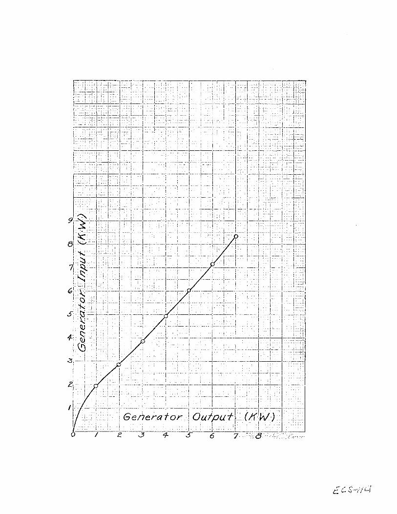
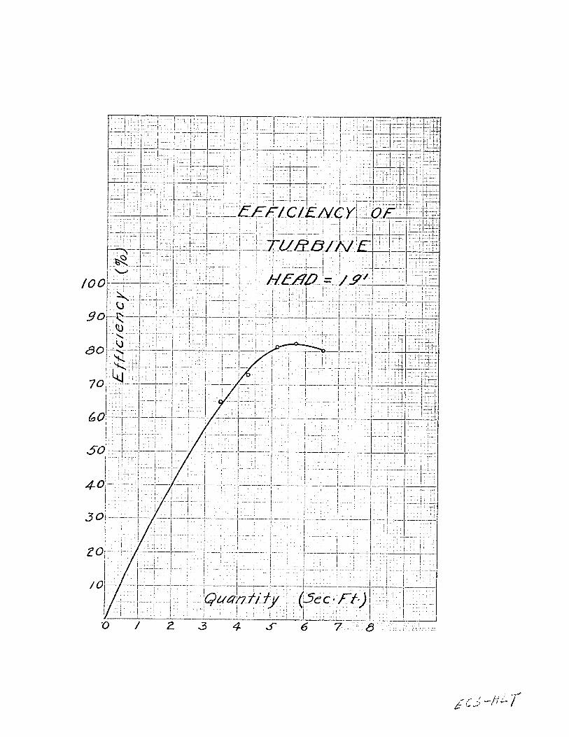
The efficiency curve of the turbine (Appendix
B and C) was plotted from data furnished by the Gen-
eral Electric Company.
The efficiency curve of the turbine (Appendix
D) was plotted from a Holyoke test 466, made January
17, 1890, upon a 12 inch wheel of the same series as
the wheel to be installed.
A study of the curves shows that to obtain
a good economy, the plant should be operated at a load
varying from five to seven kilowatts. At smaller loads
the turbine and generator losses increase rapidly; at
higher loads the turbine and pipe losses increase
rapidly.
23.
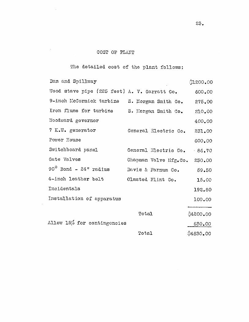
COST OF PLAITT
The detailed cost of the plant follows:
Dan an& Spillway
Vood stave pipe (225 feet)
9-inch McCormick turbine
Iron flume for turbine
Yloodward governor
7 K.W. generator
Power House
Switchboard panel
Gate Valves
900 Bond - 24" radius
4-inch leather belt
Incidentals
Installation of apparatus
A. V. Garratt Co.
S. Morgan Smith Co.
S. Morgan Smith Co.
General Electric Co.
General Electric Co.
Chapman Valve Mfg.Co
Davis & Farnum Co.
Olmsted Flint Co.
Total
Allow 15fo for contingencies
Total
V1200.00
600.00
275.00
210.00
400.00
231.00
600.00
86.70
230.00
59.50
15.00
192.80
100.00
:?4200.00
630.00
4830.00

24.
COST OF POIER.
Assuming the plant will be run for eight
hours per day, at an efficiency of 55 per cent.
H. P. : 1.5 x 62.5 x .55 x 19 x 24 - 5.36550
5.36 x .746 = 4 K-W.
Interest and. depreciation on development at 10%.
4800 x 010 = 1)480
480 - .120 per K. W. year.4
_ 120 = 6O.041 per K. V1. hour.8 x 365
Cost per K.V7.H. from Lawrence Gas Co.
for a lighting load
Cost per K.VI.H. of hydro-electric power
Saving per K.!.H.
00.125
0.041
90.084
Saving per year - 365 days of 8 hours each
.084 x 8 x 365 = .245.
The cost of operation will be very small, as the
process consists only in starting and, stopping of the
turbine and the lubrication of the bearings.

25.
RECOIEUTDAT IOITS
Wve conclude, from the foregoing investi-
gation, that the plant is feasible, and recommend
that it be built.
We further recommend that the owner build
the dam, the spillway, and the power house, thus re-
ducing the initial cost of the plant by very nearly
.41500. 00.
We also recommend that construction of the
dam and spillway be started in the early spring in
order that the dam will have had sufficient time to
become thoroughly settled before the spring freshets
of the following year.
Respectfully submitted,

A P P E N D I X A.

. . ..... .T
+ ~A I 7FIT
7 7 V1 7 .4J2c r~£ ~ fP 7/0Lo5I
r17_'~~~ -78-1OfLS-,
I 1I
117I ri 7
__ I
(Sec.F/')
1 7 c5~
Ii
I-
' c
I
.4
j

APPENDI CES B&C.

- - -
-7
/00
go
do-
7 7
40
S--
/0
'I'
1 1
I I
f 7
0 / 2
11 tT
- -7
7 --7 7-
-7
_771= -- 1 -71777 n _ -
71 771-i F~1 I I T~2~V
__~~YE /fCCC Qr4<j
ji-1 7.
IIt
-T 7
Get'en icr-04
3 4 4
I 7£
77177---4--
i iS6 T ,
ol
.1- { 1 ~ ri-_____ ___ I i I Ii
1,-I [ I I I -~
______ I _______ __________
t I1 I I
I I
I I -1 1II I I __
I I -1- - I6>' I I F-
I L ~1Ilj~Z~ ___
f I
'7; tI _____
I I It
___ j jili1 1
-~ --- 1
I I I
I II
~- I IL.i:. I &eflerctOr 04'/pa< (/i~kV)___ I __ I _________ Io / ~ 6 :7 8
,' .- '

A P P E N D I X D.
III ~ 77-7
7 ft
i-- 777,
J I
Z 0
oti
_L'_5
I _-_6_ _ _

A P P E Y D I X E.

6 - ------ V~f~
i - A -

APPENDIX F.
DATA FOR CURVES.
The size of the pipe was limited by the
losses, due to friction. The loss in a pipe line
in feet of head is expressed by the formula F V2D 2~g
where "f" is the friction coefficient of the pipe,
"1" is the length in feet, "d" the diameter in feet,
"TvI the velocity in the pipe in feet per second, and
"g1 the acceleration due to gravity. This formula
shows that for a given quantity of water, the head
lost in the pipe is inversely proportional to the fifth
power of the diameter because the velocity is inversely
proportional to the second power of "d".
If the load cycle of the plant were known,
the most economical size of pipe could be accurately
calculated. This would be computed by making the sum
of the value of the lost power and the depreciation
charges a minimum. The loss cannot be computed due
to it being dependent upon the quantity of water flowing,
and as this is a variable, it became necessary to choose
a pipe which gave a reasonable lost head without too
great a velocity.
An eighteen inch pipe was decided upon, since

F
it came closer to the requirements than any other;
the curve of lost head in feet plotted against the
quantity of water flowing is shown in the Graph
(Appendix A).
The lost head is.made up of an entrance
loss, a loss in the bend, and a friction loss in the
pipe. The entrance loss and the loss at the bend are
both proportional to the square of the velocity. The
entrance loss being C as is also the loss at the2 g
bond; C for the entrance loss, being .5 and that for
the bend about .194. The entrance loss will be dimin-
ished by flaring the entrance, so that the entrance
velocity will not exceed 1.5 feet per second.
The loss at the bend is a function of d/r
where "d" is the diameter of the pipe and "r" the radius
of the bend. For this case d/r is .75, and "0" is .194.
The velocity of the water will not exceed four feet per
second. The lost head at the bend cannot exceed
.194 x 16 .048 feet, which is too small to take into64
account, since the level of the water in the reservoir
will vary much more than that.
Other factors which should be taken into ac-
count in the construction of pipe lines are water, hammer
and vacuum in the pipe. Since the pipe line in this
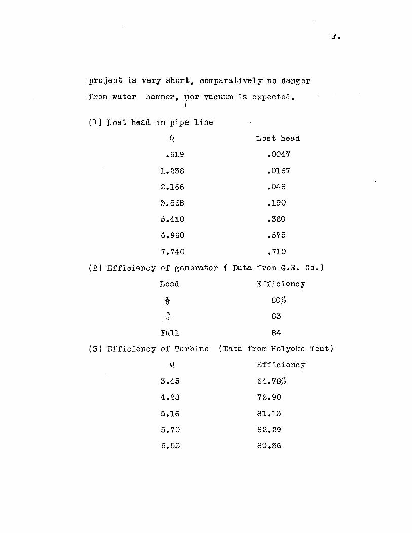
F.
project is very short, comparatively no danger
from water hammer, nor vacuum is expected.I
(1) Lost head in pipe line
q Lost head
.619 .0047
1.238 .0167
2.166 .048
3.868 .190
5.410 .360
6.960 .575
7.740 .710
(2) Efficiency of generator ( Data from G.E. Co.)
Load Efficiency
280%
3 83
Full 84
(3) Efficiency of Turbine (Data from Holyoke Test)
Q Efficiency
3.45 64.78;
4.28 72.90
5.16 81.13
5.70 82.29
6.53 80.36
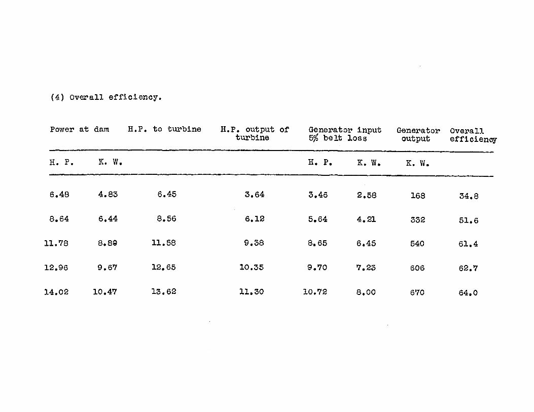
(4) Overall efficiency.
Power at dam H.P. to turbine H.P. output ofturbine
Generator input5% belt loss
Generatoroutput
Overallefficiency
H. P. K.W. H. P. K. W. K. W.
6*48
8.64
11.78
12.96
4.83
6.44
8.89
9.67
6*45
8.56
11.58
12.65
3.,64
6.12
9*38
10.35
3*46
5.64
8.65
9.70
2*58
4.21
6*45
7.23
168
540
606
34*8
51.6
61*4
62.7
13.62 11.30 10.7214.02 10.47 8.00 670 64.0

F.
'IJR READINGS.
Date Read Date Read Date Read Date Read
Sept. 8 .85' Oct. 1 .49' 1ov. 1 .85' Dec. 1 .60'
" 9 .85 "T 2 .48 " 2 .85 "t 2 .65
10 .83 3 47 " 3 .84 " 3 .75
"11 .84 " 4 46 " 4 .80 " 4 .65
" 12 1.10 " 5 .45 " 5 .85 " 5 .65
13 1.05 " 6 .45 " 6 .85 " 6 .70
" 14 1.00 " 7 .50 IT 7 .95 IT 7 .65
" 15 .93 it 8 .60 IT 8 1.05 it 8 .60
16 1.03 " 9 .70 "T 9 .85 It 9 .60
" 17 1.00 " 10 .70 it 10 .95 " 10 .65
"T 18 .85 " 11 .70 " 11 .75 " 11
"T 19 .75 " 12 .80 " 12 .70 " 12 .65
i 20 .80 " 13 .80 " 13 .75
" 21 .63 i 14 .80 T 14
" 22 .63 "? 15 .90 i 15
" 23 .63 " 16 .90 " 16 .65
" 24 .55 " 17 " 17 .60we ir
" 25 .50 " 18 - 18 .60broken
" 26 .50 it 19 " 19 .50
" 27 .50 I 20 " 20 .90
" 28 .50 it 21 " 21 .85
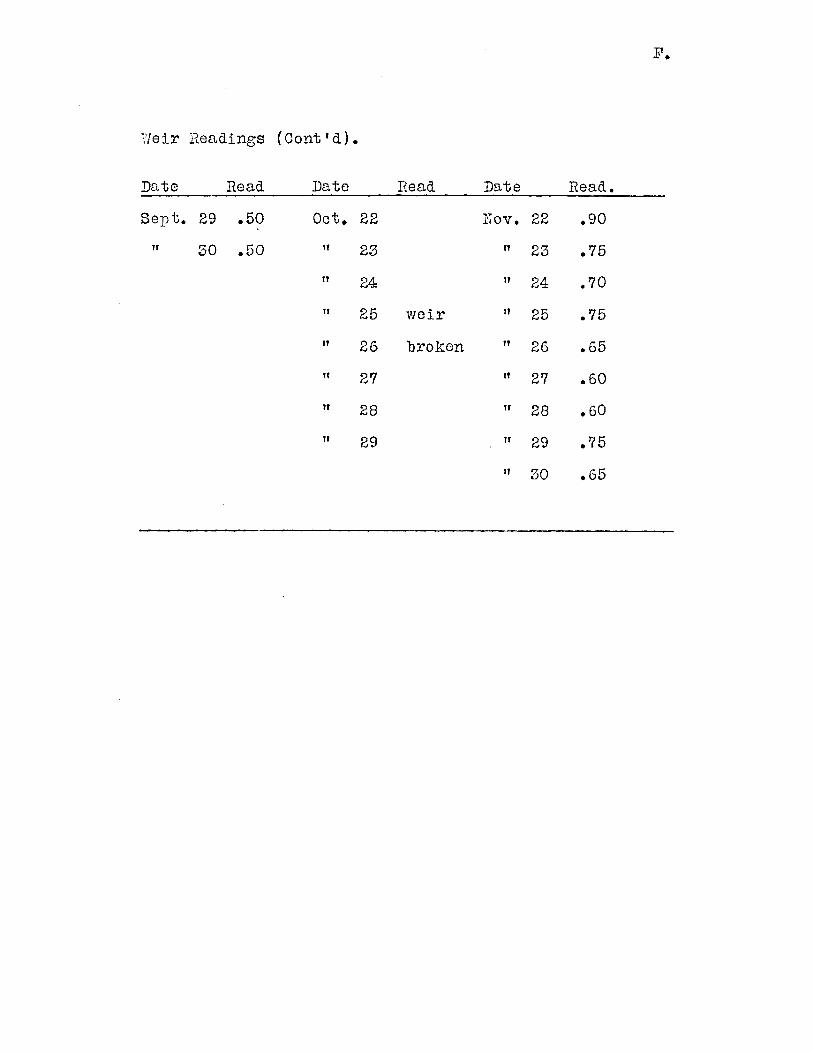
P.
Weir Readings (Cont'd).
Date Read Date Read Date Read.
Sept. 29 .50 Oct. 22 Uov. 22 .90
" 30 .50 IT 23 " 23 .75
" 24 "t 24 .70
" 25 weir "t 25 .75
" 26 broken " 26 .65
" 27 "t 27 .60
" 28 "t 28 .60
" 29 . 29 .75
"? 30 .65

ol


K
