an object model framework for interface management … · an object model framework for interface...
TRANSCRIPT

An Object Model Framework for Interface Management in Building
Information Models
by
Qian Chen
Dissertation submitted to the Faculty of the
Virginia Polytechnic Institute and State University
in partial fulfillment of the requirement for the degree
Doctor of Philosophy in
Environmental Design and Planning
Chair:
Dr. Yvan Beliveau
Dr. Georg Reichard
Committee Members:
Dr. Michael Garvin
Prof. Michael O’Brien
July 13, 2007, Blacksburg, Virginia
Keywords: Interface Management, Interface Issues, Building Information Model, Housing
Construction, Interface Object Model, Integrated Project Delivery
Copyright 2007 by Qian Chen
ALL RIGHTS RESERVED

An Object Model Framework for Interface Management in Building
Information Models
Qian Chen
ABSTRACT
The construction industry’s overall project performance is significantly reduced by numerous
interface issues that also hinder its industrialization. Interface Management (IM) is becoming
critical to the success of multidisciplinary construction projects. This research deals with three
challenging problems associated with IM: 1) how to build a holistic understanding of interface
issues for developing all-around IM solutions; 2) how to define and present interface information
in a unified, accurate, and efficient way to improve information sharing, coordination, and
implementation; and 3) how to resolve interface issues as a whole to optimize IM performance.
Comprehensive cause factors of interface issues are investigated from different yet
interrelated perspectives. These cause factors allow for the development of an object data model
and a systematic IM strategy. The findings of this multi-perspective approach not only add a
holistic view of interface issues to the existing body of knowledge but also provide a theoretical
base for researchers and practitioners to seek all-around IM solutions.
As a key innovation, an object view of interfaces is defined, resulting in a unified way of
presenting interface information. This new technique of modeling interfaces as knowledgeable,
intelligent, and active objects is far superior to the traditional use of simple relationships. The
proposed Interface Object Model (IOM) framework is the first in the literature to present a
comprehensive data structure and its dependencies of interface information for object modeling.
This can greatly improve the quality and interoperability of modeled interface information.
When integrated into a Building Information Modeling (BIM) approach, this technique can
significantly enhance BIM capabilities for interface-related coordination, decision-making,
operation, and management.

iii
As a first application, a systematic model-based IM strategy is conceptually developed,
which provides a good foundation for creating an implementation environment for the developed
interface model. This strategy aims to resolve interface issues as a whole throughout a complete
project process.
The multi-perspective approach, the generically structured IOM, and the conceptual,
systematic IM strategy all target broad applications. Individually or jointly, they can also be
applied to other domains beyond construction.
iv
Acknowledgements
I would like to express my deepest appreciation to Professor Yvan Beliveau, my advisor. He has
generously provided his invaluable insights, inspiring ideas, constant guidance, and warm
encouragement. With his generous financial support, it is possible for me to finish my Ph.D.
study. Also, his kind advice for my career and life are highly appreciated. It has been my
pleasure to have him as my mentor and friend.
I would like to give my great thanks to Professor Georg Reichard, my co-advisor. He has
generously given his time and shared his experience with me. He is always available when I need
help and guidance in the development of my research. He is open-minded and very supportive. I
highly appreciate his sharing of teaching experience with me when I worked as his Teaching
Assistant. I feel very fortunate to have worked with and learned from him.
I would like to thank my committee members: Professor Michael O’Brien for his
instructive advice and kind support—I have learned a great deal from him to shape my work
attitude, research enthusiasm, and personality; Professor Michael Garvin for his insightful
comments and advice. Also, appreciation is given to Professor Ron Wakefield, who opened the
door for me to join Virginia Tech and guided me through my first years of Ph.D. study and
research, and Professor Thomas Mills, who has offered his kind assistance when I need any help.
Thanks also goes to my colleagues and close friends: Victor Quagraine, Brendan Johnston,
Younghan Jung, and many others. They have contributed their suggestions and experience to my
study. They also make my journey here full of joys and fun.
Finally, special appreciation is given to my family: my mother, Rongfang Yang, my father,
Siqian Chen, my brother, Hong Chen, and my dear husband, Jia Liu. Without their endless love
and strong support, none of my achievements would be possible. My deepest thanks goes to my
grandma. I always miss her endless love and care, which brought me the happiest childhood.

v
Table of Contents
CHAPTER 1: INTRODUCTION............................................................................................. 1
1.1 BACKGROUND................................................................................................................ 1
1.2 PROBLEM STATEMENT ................................................................................................... 4
1.3 SCOPE OF RESEARCH ..................................................................................................... 5
1.4 RESEARCH OBJECTIVES ................................................................................................. 7
1.5 RESEARCH METHODOLOGY ........................................................................................... 8
1.6 RESEARCH CONTRIBUTIONS........................................................................................... 9
1.7 RESEARCH LIMITATIONS.............................................................................................. 12
1.8 DISSERTATION ORGANIZATION.................................................................................... 13
CHAPTER 2: LITERATURE REVIEW .............................................................................. 15
2.1 THE EVOLUTION OF IM................................................................................................ 15
2.2 IM IN MANUFACTURING .............................................................................................. 19
2.2.1 Manufacturing IM Strategies ............................................................................ 19
2.2.2 Lean Production ................................................................................................ 21
2.2.3 Agile Manufacturing......................................................................................... 25
2.3 IM IN OFFSHORE CONSTRUCTION ................................................................................ 26
2.4 INTERFACE RELATED RESEARCH ................................................................................. 28
2.4.1 Defining and Categorizing Interfaces ............................................................... 28
2.4.2 Physical Interfaces between Building Components.......................................... 33
2.4.2.1 CladdISS for Windows and Cladding System............................................ 33 2.4.2.2 Knowledge-Based System for Wooden Construction ................................ 36
2.4.3 Interfaces among Various Construction Parties................................................ 38
2.4.4 Design-Construction Interface .......................................................................... 40
2.4.5 Contractual Interface......................................................................................... 45
2.4.6 Systems Approaches ......................................................................................... 48
2.4.6.1 Systems Engineering.................................................................................. 48 2.4.6.2 Systems Engineering Approach for Dynamic IM ...................................... 48 2.4.6.3 Building Systems........................................................................................ 50 2.4.6.4 Systems Integration in Housing Construction........................................... 51
2.5 INFORMATION MODELING FOR INTERFACES AND IM ................................................... 53
vi
2.5.1 3D/4D Visualization ......................................................................................... 53
2.5.2 Object-Oriented CAD and Supporting Modeling Methods .............................. 54
2.5.3 Industry Foundation Classes (IFCs).................................................................. 57
2.5.4 Building Information Modeling (BIM)............................................................. 61
2.5.5 Unified Modeling Language (UML) ................................................................ 63
CHAPTER 3: INTERFACE-RELATED BUILT ENVIRONMENT ANALYSIS............ 66
3.1 A MULTI-PERSPECTIVE APPROACH ............................................................................. 66
3.2 PERSPECTIVE ONE: PEOPLE/PARTICIPANTS.................................................................. 68
3.2.1 Poor Communication among Parties ................................................................ 69
3.2.1.1 Lack of Communication............................................................................. 70 3.2.1.2 Delayed or Ineffective Communication..................................................... 70
3.2.2 Poor Coordination among Parties ..................................................................... 71
3.2.2.1 Unaware of Interface Issues...................................................................... 72 3.2.2.2 Unaware of Interface Ownership & Responsibilities................................ 72 3.2.2.3 Lack of Coordination between Design and Construction Parties............. 73 3.2.2.4 Lack of Resource and Personnel to Facilitate Coordination.................... 73 3.2.2.5 Lack of Coordination among Specialties .................................................. 73 3.2.2.6 Unable to Work on Site Simultaneously .................................................... 74 3.2.2.7 Unwilling to Bear Coordination and Resolution Responsibilities ............ 74
3.2.3 Poor Decision-Making ...................................................................................... 74
3.2.3.1 The Complexity and Uncertainties of a Project ........................................ 75 3.2.3.2 Bad Policy for Handling Inter-Company Relationships ........................... 75 3.2.3.3 Lack of Information or Outdated Information .......................................... 76 3.2.3.4 Slowness of Owner’s Decision-Making..................................................... 76 3.2.3.5 Lack of Experience in Design and Construction....................................... 76
3.2.4 Financial Problems............................................................................................ 77
3.2.4.1 Delayed Payments ..................................................................................... 77 3.2.4.2 Low Budget for Design and Construction................................................. 78 3.2.4.3 Cost Disputes among Parties .................................................................... 78
3.3 PERSPECTIVE TWO: METHODS/PROCESSES .................................................................. 79
3.4 PERSPECTIVE THREE: RESOURCES ............................................................................... 81
3.5 PERSPECTIVE FOUR: DOCUMENTATION ....................................................................... 82
3.6 PERSPECTIVE FIVE: PROJECT MANAGEMENT ............................................................... 84
3.7 PERSPECTIVE SIX: ENVIRONMENT ............................................................................... 85
3.8 FINDINGS AND OUTCOMES........................................................................................... 86

vii
CHAPTER 4: INTERFACE OBJECT MODEL FRAMEWORK ..................................... 91
4.1 INTRODUCTION TO THE IOM........................................................................................ 91
4.1.1 What is a Model? .............................................................................................. 91
4.1.2 What is an Object Model?................................................................................. 92
4.1.3 What is the IOM?.............................................................................................. 92
4.1.3.1 An Object View of Interfaces..................................................................... 93 4.1.3.2 Important Modeling Concepts in the IOM ................................................ 93
4.2 INTRODUCTION TO THE IOM FRAMEWORK.................................................................. 94
4.3 ARCHITECTURE OF THE IOM FRAMEWORK.................................................................. 95
4.4 FRAMEWORK DEVELOPMENT....................................................................................... 96
4.4.1 Interface Categorization.................................................................................... 96
4.4.1.1 Category One: Physical Interface ............................................................. 98 4.4.1.2 Category Two: Functional Interface......................................................... 98 4.4.1.3 Category Three: Contractual Interface..................................................... 99 4.4.1.4 Category Four: Organizational Interface................................................. 99 4.4.1.5 Category Five: Resource Interface ......................................................... 100
4.4.2 Interface Object Hierarchy.............................................................................. 101
4.4.3 UML Interface Object Class Diagrams........................................................... 103
4.4.3.1 Data Structure ......................................................................................... 106 4.4.3.2 Simple Interface and Reference Interface ............................................... 107 4.4.3.3 Physical Interface Object Classes........................................................... 107
4.4.4 System Data Dependency ............................................................................... 110
4.4.5 Relational Diagrams........................................................................................ 113
CHAPTER 5: INTERFACE OBJECT MODEL VALIDATION..................................... 118
5.1 THE DECISION-MAKING MODEL................................................................................ 118
5.1.1 The Decision-Making Model for Physical Interface Modeling...................... 118
5.1.2 A Decision-Making Scenario.......................................................................... 119
5.1.3 Interface Modeling Examples ......................................................................... 121
5.2 IOM VALIDATION IN SELECTED HOUSING CONSTRUCTION PROCESSES .................... 127
5.2.1 The U.S. Housing Construction Process......................................................... 127
5.2.2 Foundation Wall Installation........................................................................... 132
5.2.2.1 Foundation Wall Installation Process..................................................... 134 5.2.2.2 IOM Validation........................................................................................ 137
5.2.3 Componentized Superstructure Framing ........................................................ 141
5.2.3.1 Componentized Superstructure Framing Process................................... 141

viii
5.2.3.2 IOM Validation........................................................................................ 144
5.3 BENEFITS AND POTENTIAL APPLICATIONS ................................................................. 148
CHAPTER 6: SYSTEMATIC MODEL-BASED INTERFACE MANAGEMENT........ 150
6.1 INTRODUCTION TO THE STRATEGY............................................................................. 150
6.2 CONCEPTUAL DEVELOPMENT .................................................................................... 151
6.2.1 IM Sub-Processes for a Complete Project Process ......................................... 152
6.2.1.1 Project Definition and Conceptual Design ............................................. 154 6.2.1.2 Detailed Design....................................................................................... 155 6.2.1.3 Subcontract.............................................................................................. 155 6.2.1.4 Plan and Schedule ................................................................................... 156 6.2.1.5 Construction and Assembly ..................................................................... 157 6.2.1.6 Operation, Maintenance, Retrofit, and Salvage...................................... 158
6.2.2 The Interface Modeling Core.......................................................................... 159
6.2.3 Systematic Model-Based IM........................................................................... 161
6.3 DISCUSSION OF APPLICATIONS .................................................................................. 163
CHAPTER 7: CONCLUSIONS AND RECOMMENDATIONS...................................... 168
7.1 RESEARCH FINDINGS ................................................................................................. 168
7.1.1 A Multi-Perspective Analysis ......................................................................... 168
7.1.2 A Comprehensive IOM Framework ............................................................... 169
7.1.3 A Systematic Model-Based IM Strategy ........................................................ 169
7.1.4 IM Benefits ..................................................................................................... 170
7.2 RECOMMENDATIONS FOR FUTURE RESEARCH ........................................................... 171
7.2.1 Further Development of the IOM ................................................................... 171
7.2.2 Incorporation of the IOM with the IFC........................................................... 173
7.2.3 Strategic Development of IM.......................................................................... 175
7.2.4 Incorporation of IM with Lean and Agile....................................................... 176
REFERENCE…........................................................................................................................ 177
ix
List of Figures
Figure 1-1: Overall Research Scope ............................................................................................... 6
Figure 2-1: Complexities of IM (Pavitt and Gibb 2003, with permission from ASCE)............... 31
Figure 2-2: Cladding Interface Matrix (Pavitt and Gibb 2003, with permission from ASCE) .... 35
Figure 2-3: Typical Interface Drawing (Pavitt and Gibb 2003, with permission from ASCE).... 36
Figure 2-4: Characteristics of a Building Construction System (Nakajima 1998, with permission from Blackwell Publishing) .................................................................................................. 37
Figure 2-5: Analytical Design Planning Technique (AdePT) (Austin et al. 1999, with permission from Thomas Telford Ltd) .................................................................................................... 42
Figure 2-6: a) Partitioned Design Structure Matrix; b) Modified Information Matrix (Bogus et al. 2002, with permission from ASCE)...................................................................................... 45
Figure 2-7: A Cross Functional Team (Miles and Ballard 2002, with permission from World Scientific Publishing Company) ........................................................................................... 47
Figure 2-8: IFC Object Model Architecture (Wix and Liebich 1997, with permission from CIB)............................................................................................................................................... 59
Figure 2-9: Conflicts Identified in a BIM (Engineering News-Record (ENR), with permission from ENR) ............................................................................................................................ 62
Figure 2-10: An Example of a Class Diagram.............................................................................. 65
Figure 3-1: The Method of the Cause and Effect Diagram .......................................................... 67
Figure 3-2: The C&E Structure of the Multi-Perspective Approach............................................ 68
Figure 3-3: The Major Causes in the People/Participants Perspective ......................................... 69
Figure 3-4: The Minor Causes and Sub-factors for Poor Communication................................... 69
Figure 3-5: The Minor Causes for Poor Coordination.................................................................. 72
Figure 3-6: The Minor Causes for Poor Decision-Making........................................................... 75
Figure 3-7: The Minor Causes for Financial Problems ................................................................ 77
Figure 3-8: Interface Issue Cause Factors from the Methods/Processes Perspective................... 80
Figure 3-9: Interface Issue Cause Factors from the Resources Perspective ................................. 82
Figure 3-10: Interface Issue Cause Factors from the Documentation Perspective....................... 83
Figure 3-11: Interface Issue Cause Factors from the Project Management Perspective .............. 85
Figure 3-12: Interface Issue Cause Factors from the Environment Perspective........................... 86
x
Figure 3-13: The Generation of Interface Management and Control Elements for the People/Participants Category ................................................................................................ 88
Figure 3-14: Potential Elements for Interface Management and Control..................................... 89
Figure 3-15: Systems Approach: Integrated Interface Management ............................................ 90
Figure 4-1: The Conventional View of an Interface..................................................................... 93
Figure 4-2: The Innovative View of an Interface ......................................................................... 93
Figure 4-3: Architecture of the IOM Framework ......................................................................... 95
Figure 4-4: Interface Categorization............................................................................................. 98
Figure 4-5: Interface Object Hierarchy....................................................................................... 102
Figure 4-6: UML Physical Interface Object Class Diagram....................................................... 105
Figure 4-7: Physical Interface Class ........................................................................................... 108
Figure 4-8: Self_Adhesive Class ................................................................................................ 109
Figure 4-9: System Data Dependency ........................................................................................ 112
Figure 4-10: Data Dependency Between Physical Interface Objects and Facility Components 114
Figure 4-11: The Simple Type of Reference Interface ............................................................... 115
Figure 4-12: The Compound Type of Reference Interface......................................................... 116
Figure 4-13: The Comprehensive IOM Framework ................................................................... 117
Figure 5-1: The Decision-Making Model for Physical Interface Modeling ............................... 119
Figure 5-2: A Decision-Making Scenario................................................................................... 120
Figure 5-3: The Physical Interface Modeling Structure for the Selected Physical Condition.... 121
Figure 5-4: Glass Panel Bottom Sectional Detail ....................................................................... 122
Figure 5-5: Interface Object Modeling Example I...................................................................... 123
Figure 5-6: Granite Cladding Detail ........................................................................................... 124
Figure 5-7: Interface Object Modeling Example II .................................................................... 126
Figure 5-8: Use Case Diagram for the Operation of the Homebuilding Process........................ 128
Figure 5-9: Sequence Diagram for Interactions Between Participants in a Homebuilding Process............................................................................................................................................. 130
Figure 5-10: “Stick-Build” Framing Process.............................................................................. 131
Figure 5-11 : Typical Physical Interface Failures....................................................................... 132
Figure 5-12: Overall Structure of Foundation and Superstructure Subsystems ......................... 133
Figure 5-13: Facility Components and Their Relationships in Foundation Wall Installation.... 138
xi
Figure 5-14: Interface Object Model for Foundation Wall Installation...................................... 140
Figure 5-15: Facility Components and Their Relationships in Componentized Superstructure Framing ............................................................................................................................... 145
Figure 5-16: Interface Model for Componentized Superstructure Framing ............................... 147
Figure 6-1: The New IM Strategy for a Complete Project Process ............................................ 152
Figure 6-2: IM Sub-processes in a Complete Project Process .................................................... 153
Figure 6-3: The Interface Modeling Core................................................................................... 160
Figure 6-4: Systematic Model-Based IM Process Flow Chart ................................................... 162
Figure 7-1: Interface Modeling Capabilities of the Prototype .................................................... 172
Figure 7-2: The Implementation in Systems Integration ............................................................ 173
Figure 7-3: IFC Model Architecture (IAI 2006, with permission from IAI International Council)............................................................................................................................................. 174
Figure 7-4: Self-Organizing Multi-Disciplinary Teams in APM ............................................... 176
xii
List of Tables
Table 2-1: Definitions of Previously Defined Interface Categories in the Literature................... 30
Table 2-2: Common Interface Problems from Construction Parties’ Viewpoint (Al-Hammad 2000, with permission from ASCE)...................................................................................... 39
Table 2-3: UML Model Categories............................................................................................... 64
Table 6-1: Notations for the Process Flow Chart........................................................................ 154

1
CHAPTER 1: INTRODUCTION
Chapter 1 provides the background information for this research including an overview of the
United States (U.S.) housing construction industry, definitions of interface and interface
management (IM), as well as the scope, importance and urgency of IM in construction. This
chapter also presents the problem statement, scope, objectives, methodology, contributions,
limitations of this research, and outlines the organization of this dissertation.
1.1 BACKGROUND
U.S. housing construction is selected as the main background for this research. The U.S. housing
construction (also called homebuilding) industry has been evolving toward industrialization since
the Industrial Revolution. However, compared with other industries, e.g., manufacturing, the
industrialization in housing construction has lagged far behind. Modular, pre-cut, panelization,
wet-core modules, mobile homes, and wood components have been the six most commonly used
industrialization techniques for years (U.S. Congress 1986). Nevertheless, so far, stick-build,
utilizing classical framing lumber and depending on manual labor and labor-intensive processes
during on-site construction and assembly, is still the prevailing form of “industrialized” housing.
Homebuilding is notorious for its low productivity, waste, poor quality, and out-of-date
technologies (O’Brien, Wakefield, and Beliveau 2000).
Reasons adversely affecting the industrialization of housing construction are multifaceted.
Moshe Safdie addresses some external reasons: scattered building sites and a fragmented housing
market, diverse building codes, conservative and protective trade union practices, etc. (Sullivan
1980). At the same time, the peculiarities of homebuilding, which differentiate the industry from
factory manufacturing, are also crucial causes. Those peculiarities include the poorly controlled
built environment, the complexity of construction, temporary multi-organization, and the
interdisciplinary nature of the project delivery process. Under these circumstances, the industry’s
goal—to build a high quality, energy-efficient, comfortable, and healthy house in the most
economical way—is virtually unachievable.
2
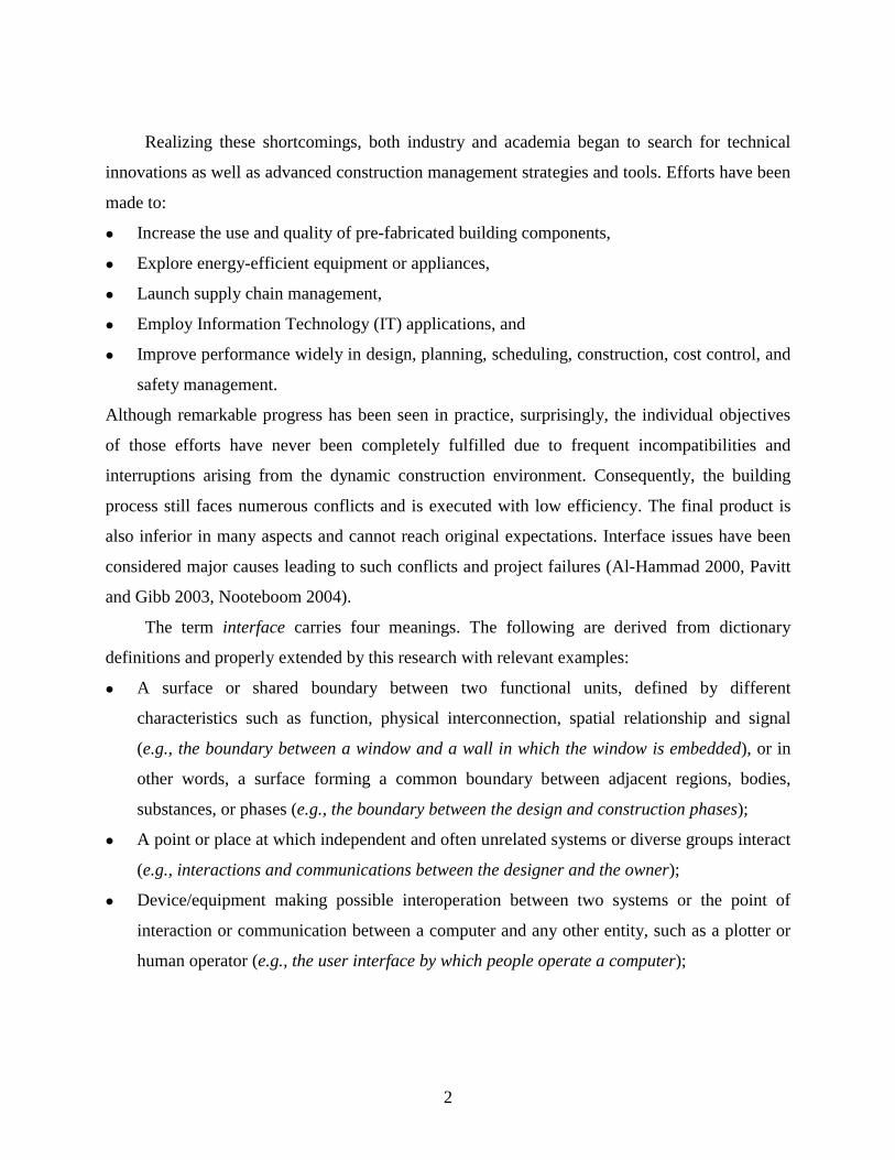
Realizing these shortcomings, both industry and academia began to search for technical
innovations as well as advanced construction management strategies and tools. Efforts have been
made to:
Increase the use and quality of pre-fabricated building components,
Explore energy-efficient equipment or appliances,
Launch supply chain management,
Employ Information Technology (IT) applications, and
Improve performance widely in design, planning, scheduling, construction, cost control, and
safety management.
Although remarkable progress has been seen in practice, surprisingly, the individual objectives
of those efforts have never been completely fulfilled due to frequent incompatibilities and
interruptions arising from the dynamic construction environment. Consequently, the building
process still faces numerous conflicts and is executed with low efficiency. The final product is
also inferior in many aspects and cannot reach original expectations. Interface issues have been
considered major causes leading to such conflicts and project failures (Al-Hammad 2000, Pavitt
and Gibb 2003, Nooteboom 2004).
The term interface carries four meanings. The following are derived from dictionary
definitions and properly extended by this research with relevant examples:
A surface or shared boundary between two functional units, defined by different
characteristics such as function, physical interconnection, spatial relationship and signal
(e.g., the boundary between a window and a wall in which the window is embedded), or in
other words, a surface forming a common boundary between adjacent regions, bodies,
substances, or phases (e.g., the boundary between the design and construction phases);
A point or place at which independent and often unrelated systems or diverse groups interact
(e.g., interactions and communications between the designer and the owner);
Device/equipment making possible interoperation between two systems or the point of
interaction or communication between a computer and any other entity, such as a plotter or
human operator (e.g., the user interface by which people operate a computer);

3
A shared logical boundary between two software components (e.g., the interface between
two construction management software components).
Although all of these interfaces can be found in construction, comparatively, the first two types
exist more widely and influence the construction process to a greater extent. Usually, interfaces
spread throughout the stages (e.g., design, manufacturing, construction, operation and
maintenance) of a housing project. They also lie between pre-fabricated building components,
individually designed and erected subsystems, or other active project entities, namely
people/participants, processes, resources, etc. The aforementioned efforts dealing with specific
technical or management issues ignore such interrelationships or interactions. As a result, diverse
interface issues, exemplified as mismatched building parts, systems performance failures,
coordination difficulties, assembly conflicts between trades, etc., occur repeatedly and greatly
reduce the homebuilder’s overall performance in terms of quality, cost, and time. Managing
interfaces, therefore, becomes an issue of significant importance.
After reviewing the characteristics of housing construction and the frequent interface issues,
this research provides a specific and precise definition for IM as follows:
Interface Management is the management of the boundaries among project entities
(people/participants, processes/phases, resources, contracts, costs, schedules,
systems/functions, and safety/risks) to enable a dynamic and well-coordinated
construction system.
This definition reflects the complex interactions among project entities in the current housing
construction environment, and simultaneously refines the goal of IM.
In the literature of building construction, interface related studies are very limited.
However, scattered research efforts are still able to disclose the most common interface issues
and to identify their potential causes. Insufficient and inaccurate interface information, as well as
inefficiencies in information sharing, are among the most often mentioned causes leading to
many critical interface issues (Al-Hammad and Al-Hammad 1996, Al-Hammad 2000, Khanzode
et al. 2000, Miles and Ballard 2002). Without sufficient information, IM, which involves
intensive decision-making, cannot be properly performed.

4
In practice, interfaces have been largely neglected by construction management personnel
because interface information has neither been adequately defined nor represented in the best
way for their use. Simultaneously, the large number of interfaces and their complexity prevent
the most capable people from visualizing potential interface issues and then managing these
issues. Computer assistance in the IM process will be essential. Thus a standard and efficient
way of presenting, recording, tracking, checking, and managing the large amount of interface
information is needed. The interface information should be easily applied to advanced IT tools.
Responding to such a need, this research aims at finding an accurate and standardized way
to present interface information as well as facilitating the use of the information in IT-
oriented interface management.
1.2 PROBLEM STATEMENT
In the construction industry, IM is an emerging area and also a very challenging task of project
management. Due to poor IM performance, numerous interface issues have significantly reduced
overall project performance in the construction project delivery process and implicitly hindered
industrialization of construction. This research identifies three critical problems associated with
IM as follows:
How to build a holistic understanding of interface issues in the current built environment for
developing all-around IM solutions;
How to define and present interface information in a unified, accurate, and efficient way to
improve information sharing, coordination, and to allow for implementation in IT
applications;
How to resolve interrelated interface issues as a whole to optimize IM performance in a
construction project.
Previous studies investigated and dealt with interface issues mainly in one specific area (Al-
Hammad and Assaf 1992; Hinze and Andres 1994; Alarcón and Mardones 1998; Miles and
Ballard 2002; Pavitt et al. 2001; Pavitt and Gibb 2003). Interface issues have seldom been
considered as a whole, and comprehensive causes for such issues are still missing. As a result,
overall IM performance in a construction project is difficult to optimize since other untreated
interface issues largely influence the ones being treated. This research conducts an innovative
5
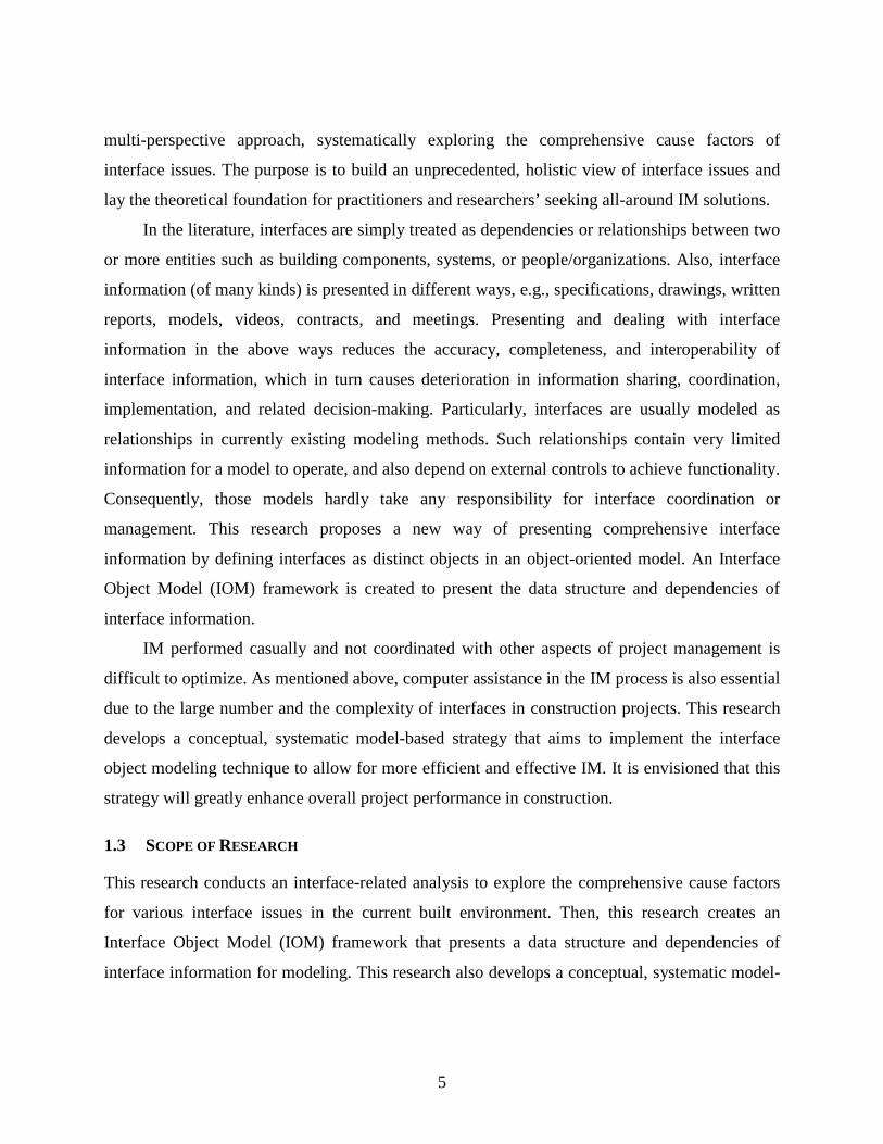
multi-perspective approach, systematically exploring the comprehensive cause factors of
interface issues. The purpose is to build an unprecedented, holistic view of interface issues and
lay the theoretical foundation for practitioners and researchers’ seeking all-around IM solutions.
In the literature, interfaces are simply treated as dependencies or relationships between two
or more entities such as building components, systems, or people/organizations. Also, interface
information (of many kinds) is presented in different ways, e.g., specifications, drawings, written
reports, models, videos, contracts, and meetings. Presenting and dealing with interface
information in the above ways reduces the accuracy, completeness, and interoperability of
interface information, which in turn causes deterioration in information sharing, coordination,
implementation, and related decision-making. Particularly, interfaces are usually modeled as
relationships in currently existing modeling methods. Such relationships contain very limited
information for a model to operate, and also depend on external controls to achieve functionality.
Consequently, those models hardly take any responsibility for interface coordination or
management. This research proposes a new way of presenting comprehensive interface
information by defining interfaces as distinct objects in an object-oriented model. An Interface
Object Model (IOM) framework is created to present the data structure and dependencies of
interface information.
IM performed casually and not coordinated with other aspects of project management is
difficult to optimize. As mentioned above, computer assistance in the IM process is also essential
due to the large number and the complexity of interfaces in construction projects. This research
develops a conceptual, systematic model-based strategy that aims to implement the interface
object modeling technique to allow for more efficient and effective IM. It is envisioned that this
strategy will greatly enhance overall project performance in construction.
1.3 SCOPE OF RESEARCH
This research conducts an interface-related analysis to explore the comprehensive cause factors
for various interface issues in the current built environment. Then, this research creates an
Interface Object Model (IOM) framework that presents a data structure and dependencies of
interface information for modeling. This research also develops a conceptual, systematic model-

6
based interface management (IM) strategy that can implement the IOM. Figure 1-1 illustrates the
overall research scope in detail.
Figure 1-1: Overall Research Scope
This scope consists of three distinguishable parts as described below:
In the first part of Figure 1-1 (A), the current built environment is analyzed to explore
comprehensive cause factors of various interface issues. In order to avoid the unilateralism, a
multi-perspective approach using the Cause-and-Effect (C & E) diagram method is employed.

7
This approach first identifies interrelated perspectives as main cause areas and then explores
major causes, minor causes, and sub-factors for interface issues within them. All the defined
cause factors are presented in the C & E diagram in a hierarchical way. Subsequently, a series of
interface management and control elements are summarized and displayed in affinity diagrams to
represent the same information in a more applicable format for future research use.
The second part of Figure 1-1 (B) focuses on creating a comprehensive IOM framework. It
starts with the creation of a framework architecture. This architecture specifies the two levels
(the Modeling level and the Application level) and the associated model components of the
proposed IOM as well as their functions. Based on the information, the model component
development processes are designed and some development examples are given. These processes
and examples will act as guidelines for the IOM’s future development. The second part also
includes an IOM validation that demonstrates how to model physical interfaces in two selected
construction processes.
The third part of Figure 1-1 (C) develops a conceptual, systematic model-based IM strategy.
The development implements three consecutive steps. Firstly, IM sub-processes that can deal
with various types of interface issues are proposed and integrated into a complete project
delivery process. Secondly, an interface modeling core is built to combine the IOM with current
BIM (Building Information Modeling) approaches. This core outlines an integrated BIM
environment. Finally, the modeling core is incorporated into the IM enhanced project delivery
process to perform model-based IM. Based on the established concept, this research discusses
how the strategy works in general and what specific functions the modeling core performs. This
will provide further clues for IM strategies for future development and implementation.
1.4 RESEARCH OBJECTIVES
The primary objective of this research is to enhance the construction industry’s overall project
performance by improving interface modeling through systematic model-based IM. Several
detailed objectives are generated below:
Perform an interface-related built environment analysis to explore the comprehensive cause
factors for various interface issues. A series of interface management and control elements
can then be identified to help develop the IOM framework and seek all-around IM solutions.

8
Create an IOM framework to present the basic data structure and dependencies of interface
information. In this comprehensive framework, the development processes and examples for
the proposed model components are presented to assist their full development in future
research.
Validate the IOM by modeling physical interfaces in two selected construction processes.
This validation is based on a fully developed physical interface object category and related
data dependencies presented in the framework. It is in preparation for one future research
task that will incorporate physical interface modeling into a currently existing BIM approach.
Develop the concept of a systematic model-based IM strategy for integrated project delivery
(IPD). This strategy aims to incorporate the IOM and BIM into an IM enhanced project
delivery process.
1.5 RESEARCH METHODOLOGY
In order to accomplish the research objectives, the following five main tasks with their subtasks
need to be performed:
1) Conduct a thorough literature review for interface issues and IM
- Review the evolution of IM and establish its importance and urgency in building and
housing construction
- Introduce IM practices in manufacturing and offshore construction
- Examine previous research work related to interface definition, interface categorization,
interface issues and causes, and IM methods and tools in building and housing
construction
- Investigate existing information modeling methods concerning interfaces and IM
- Review and evaluate the Industry Foundation Class (IFC) object model and the Unified
Modeling Language (UML) that are referred to or extensively used in this research
2) Perform an interface-related analysis of the current built environment based on a multi-
perspective approach
- Select the C&E diagram method
- Determine main perspectives/categories for the C&E diagram
9
- Determine major causes, minor causes, and sub-factors contributing to various interface
issues and present them in a well-structured, hierarchical way
- Explain those cause factors by categories
- Summarize interface management and control elements in affinity diagrams
3) Create a comprehensive framework of the IOM
- Determine the method of object-oriented modeling and the purpose of the IOM
- Determine the architecture, levels, and model components of the IOM
- Create development guidelines for model components
- Develop model components into different depths based on the research needs
4) Validate the proposed IOM
- Develop a decision-making model for the selection of appropriate physical interface
objects for modeling physical conditions
- Perform a field study to investigate and record two complete construction processes
including foundation wall installation and componentized superstructure framing
- Model physical interfaces in the selected construction processes by using UML and the
applicable physical interface objects with relevant date dependencies
5) Develop the concept of a systematic model-based IM strategy for IPD
- Propose IM sub-processes that deal with all types of interface issues in a complete
project process and present them in a process flow chart
- Build an interface modeling core that combines the IOM and BIM
- Create a systematic model-based IM strategy by incorporating the modeling core into
the IM enhanced process flow chart
- Explain how this strategy works in general and what specific functions the modeling
core performs in the systematic model-based IM strategy
1.6 RESEARCH CONTRIBUTIONS
This research makes several significant contributions to the existing body of knowledge in the
proposed area of study.
The most significant contribution of this research lies in the introduction of an object view
of interfaces and its inherent interface object modeling technique. Consequently, various types of
10
interfaces in construction projects can be accurately defined and modeled as objects in an object-
oriented modeling environment. Those objects are able to capture all data, operations, and
methods associated with real-world interfaces. They become active entities and can
automatically take actions (e.g., in decision-making and analysis processes). They can also react
to outside requests or events. In the modeling environment, interface objects outperform
interface relationships, which are neither knowledgeable nor active and depend on external
controls to achieve functionality.
This interface modeling technique can greatly enhance BIM capabilities. For example, it
can not only provide accurate and comprehensive interface information but also coordinate and
manage potential interface conflicts in broad project areas. Possible applications include but are
not limited to design, construction, team and resource organization, or cost and time management.
Modeling interfaces as objects allows for complex actions that can be of great value when
integrated into a BIM approach. The benefits include:
A building information model (BIM) enhanced with interface objects is capable of
representing information on a building project with a completeness that has not been
achieved before. This extended level of information content will improve and open new
ways for operation, process and decision-making modeling.
When it comes to change management, interface objects can act as parameters to extend
component relationships that are defined in a parametric building model. This significantly
increases the depth and breadth of automatic coordination between building or project
components when compared with mainly geometric-based coordination.
Interface objects can take actions to simulate, analyze, visualize, and finally guide field
interface operations.
Interface objects can be repeatedly used in BIMs. They incorporate past solutions and
generalize them for future use. Interface operations therefore become stable and
standardized. This leads to the best practice and optimization of interface management and
operations.
The Interface Object Model (IOM) framework developed within this dissertation is the first in
the literature to present a data structure for interface information and its data dependencies with

11
other well-known project information entities. The data structure consists of several object
categories, which cover all thematic interface types (e.g., physical, functional, organizational,
etc.) that can be found in real-world construction projects. Within these categories, applicable
interface objects can be further broken down in a hierarchical way for interface modeling.
The IOM becomes the backbone of interface modeling as well as the foundation of
interface databases. It can also supplement the IFC object model’s limited relationship types to
provide a complete data structure for BIMs. Most importantly, the IOM framework provides a
structure that is open for future development, be it corrections or extensions. Related interface
databases can also be populated with an ever-growing collection of reusable interface object
classes. The information is presented in a widely used object-oriented modeling language (UML)
that can be easily adopted by various software models and IT solutions to assist future interface
related project operations and management.
This research makes a second significant contribution in the area of identifying
comprehensive cause factors for various interface issues. It takes a multi-perspective approach to
analyzing the interface related built environment. This approach surpasses other research
methods that analyze interface issues in a loose and unilateral way. Therefore, it provides an
unprecedented understanding of what (in the current built environment) causes interface issues
and simultaneously builds a solid basis to search for all-around IM solutions. It benefits both
practitioners and researchers.
The comprehensive cause factors for various interface issues are explored from different
yet interrelated perspectives (e.g., People/Participants, Methods/Processes, etc.). Accordingly,
155 cause factors are identified and presented in a hierarchical way. Based on these factors, a
series of interface management and control elements are summarized to help develop the IOM
framework and seek all-around IM solutions in future research.
This research also conceptually develops a systematic model-based IM strategy that
provides a good foundation for creating an implementation environment for interface object
modeling. This strategy proposes to connect the IOM with current BIM approaches and merge
both models into a single application that facilitates interface-related project operations and
management. In detail, the systematic model-based IM strategy targets a complete project

12
delivery process. It applies systems engineering thinking in solving interface issues for integrated
project delivery. Sub-processes are considered interacting process components in a system for
project management. Various interfaces are modeled, coordinated, and controlled systematically
to avoid inherent issues in advance or to resolve irregular issues timely.
This research develops the strategy’s core that incorporates the IOM with a BIM to form an
integrated BIM environment, and connects sub-processes with the core for information modeling,
processing and exchange. Once fully developed, this core can be a powerful engine to monitor
thousands of interfaces, automatically check conflicts, instantly give notice of IM needs to
certain activities, but also provide a platform for interface risk analysis or the automated
generation of comprehensive IM documents and guidelines. Interface modeling is now
recognized for its strategic importance in the IM process. Ultimately, the fully developed
strategy will provide an IM tool for industry users to deal with their interface issues.
In addition, this research provides further potential for broad applications. Although this
research chooses the U.S. housing construction industry as its main background, the application
to a broader construction setting is not affected. The IOM framework can guide the development
of a widely applicable IOM in the AEC/FM (Architecture, Engineering and Construction/Facility
Management) domain. The proposed model is developed generically so that it could even be
applied anywhere outside the construction domain where interface issues are present. This
systematic IM strategy could be adapted in other project delivery environments when project
participants are willing to contribute and share project information.
1.7 RESEARCH LIMITATIONS
This research has several limitations:
First of all, most model components in the IOM framework are not developed into the
application level. The IOM’s overall efficacy might not be evident at the current stage. However,
the efficacy can be demonstrated in future research. For some highly developed components,
restrictions apply. For example, in the Interface Object Hierarchy Diagram, names for interface
subcategories and applicable objects can only be properly understood after the user has learned
the specific situations they represent. In the UML Physical Interface Object Diagram, attributes
listed for each object might not be all-inclusive and should be supplemented later on.

13
Second, this research only performs physical interface modeling to validate the IOM, and
does not demonstrate how to model other types of interfaces. The two selected construction
processes are described and modeled based on the author’s observation and understanding.
Future research should find more industry applications and further validate this model to its full
potential.
Third, the systematic model-based IM strategy is only conceptually developed. It lacks
detail for immediate implementation. Future research is needed to help this model-based IM
strategy achieve extensive usage and success in construction project management.
1.8 DISSERTATION ORGANIZATION
This dissertation is organized in the following seven chapters:
Chapter 1 Introduction: Gives background information leading to the study; describes the
statement of the problem; defines the research’s scope, objectives, and methodology; and
explains contributions and limitations of this research. Chapter 1 also presents the organization
of this dissertation.
Chapter 2 Literature Review: Reviews the evolution of IM in construction and
establishes its importance and urgency. IM practices in manufacturing and offshore construction
are introduced. This chapter also reviews research efforts that define and categorize interfaces,
identify interface issues and causes, and seek IM strategies and tools. Finally, information
modeling methods in the studied area are discussed and an examination of the IFC and UML is
presented.
Chapter 3 Interface-Related Built Environment Analysis: Presents a multi-perspective
approach that analyzes the current built environment in search of comprehensive cause factors
for various interface issues. The C&E diagram with six interrelated categories (perspectives) is
illustrated and explained. According to those cause factors, a series of interface management and
control elements are identified and presented in affinity diagrams.
Chapter 4 Interface Object Model Framework: Presents a comprehensive IOM
framework. The framework consists of two levels where five model components exist. Level one,
the Modeling Level, presents the data structure of interface information in class models. Level

14
two, the Application Level, presents data dependencies of interface information. How far each
model component is developed is determined based on the needs of this research.
Chapter 5 Interface Object Model Validation: Presents the validation process for the
proposed IOM. This chapter first presents a decision-making model that shows how to select
appropriate physical interface object subcategories and applicable objects for modeling different
types of physical conditions. Then two housing construction processes, foundation wall
installation and componentized superstructure framing, are described. Following each of them,
physical interface modeling is presented in UML.
Chapter 6 Systematic Model-Based Interface Management: Presents a conceptually
developed systematic model-based IM strategy in an integrated process flow chart. This strategy
is based on an IPD process and incorporates the IOM, the BIM approaches, and the IM
procedures. How this strategy works in general and the functions of the modeling core in the
process are discussed.
Chapter 7 Conclusions and Recommendations: Summarizes the research findings
including the comprehensive cause factors of interface issues, the IOM framework, and the
conceptually developed systematic model-based IM strategy. This chapter also recommends
directions and specific tasks for future research.

15
CHAPTER 2: LITERATURE REVIEW
This chapter first presents the evolution of IM (Interface Management) in construction and
simultaneously establishes its importance and urgency. Then, IM practices in manufacturing and
offshore construction are briefly introduced. Following this is an examination of relevant
research work in defining interfaces and interface categories, identifying interface issues and
causes, and seeking IM strategies and tools, which helps build the foundation of this research.
Finally, modeling methods for presenting interface information and managing interfaces are
investigated; the IFC and UML are reviewed and evaluated. Based on the literature review, the
best approach for defining and modeling interface information is developed.
2.1 THE EVOLUTION OF IM
IM is a very new topic in many industries. IM is not uniquely defined and usually varies based
on an industry’s characteristics and management needs. In the following, several construction-
related IM definitions are introduced.
The first definition is from the offshore construction industry involving construction of
structures and pipelines in a marine environment for the production and transmission of oil and
gas. Construction in a marine environment is dangerous, therefore offshore construction mainly
depends on modular construction—assembling individual modules onshore and lifting them into
place. There, IM is defined as “the management of common boundaries between people, systems,
equipment, or concepts” (Nooteboom 2004). In the civil engineering construction field,
Wideman (2002) provides two definitions for IM: 1) “the management of communication,
coordination and responsibility across a common boundary between two organizations, phases,
or physical entities which are interdependent;” and 2) “managing the problems that often occur
among people, departments, and disciplines rather than within the project team itself.” These
three definitions jointly define what IM means in construction and what scope is covered by IM.
IM has been a hidden aspect of project management for a long time (Nooteboom 2004). Only
recent years have seen an increased awareness of this missing link in the construction industry.
In some specific construction domains, e.g., offshore-construction, IM has become a critical area
16
of project management. However, in building and housing construction, interface issues and IM
have still not received wide acceptance and relevant research contributions are scarce. In the
following, starting from offshore construction, continuing to building construction, and finally
reaching housing construction, some real world interface issues with their adverse effects are
reviewed. Although this is not an all-inclusive list of interface issues, through these instances the
importance and urgency of IM can be visualized.
In offshore construction, serious cost overruns and delays often result from poorly defined
interfaces between different scopes of work or equipment supply, and failure to properly manage
resulting conflicts (Nooteboom 2004). Usually, contractors can easily coordinate interface issues
within their teams by focusing on work scopes and schedules of their own. Nonetheless, when
such issues cut across different contractual teams, they are difficult to handle or never get
adequate attention before leading to severe consequences. Furthermore, the multiplicity of teams
involved makes it even harder to determine who has the ownership of a particular interface.
Therefore, detailed project assessment needs to be conducted to clearly define the scope of work
(INTEC Engineering 2004). In addition, IM is needed in expansive project stages and areas.
More effective IM—meaning proactive avoidance or mitigation of any project issues (e.g.,
design conflicts, installation clashes, new technology application and regulatory challenges)—is
the key of the successful delivery of mega-projects on time and on budget (Nooteboom 2004).
In building construction, physical interfaces, joints, and connections between different
elements or sections cause many critical problems for building design, manufacture, construction,
and operation throughout the life of the buildings. Conflicts on physical interfaces usually reduce
the constructability. Additionally, poor management and control over organizational and
contractual interfaces also lead to project failures. As noticed, contractual interfaces are one of
the leading causes resulting in physical interface problems. According to O’Brien and Willmott
(2001), if the façade is split into several work packages, the interfaces might not be properly
designed, followed by serious physical interface issues at the construction stage. Fritschi
(2002/2003) indicates that interface issues arising from the coincidence of different processes or
competence areas form weak points of quality.

17
The workforce now in building construction is mainly subcontractor-based. The general
contractor (GC) has to be the construction coordinator who plans and manages the interfaces
between works and subcontractors. GCs’ needs for effective IM have been forcefully
emphasized (Gibb 1995). Moreover, Pavitt and Gibb (2003) state that IM is crucial in many
project areas including design, procurement, logistics, programming, contracting, management,
external influences, and human relationships.
In most traditional project delivery systems (non Design-Build), architects usually take
coordination responsibilities for interface design issues while project managers or
superintendents concentrate on field interface conflicts. In that case, design and construction
parties work separately with limited cooperation and coordination. The design stage is performed
with little or no constructability input from contractors, and the designers are seldom involved in
the construction stage. Indeed, interface design information is very useful for construction
planning and scheduling. According to Nakajima (1998), the assembly order for building
members and consequent activity schedule can be generated by a computer using a knowledge-
based system (KBS) that is based on such characteristics of components as the mating surfaces,
connection types, and jointing methods. This information should be provided in interface design.
The broken design-construction interface forces both the design and construction parties to
perform tasks based on their own knowledge and experience. This limitation produces numerous
interface-related design errors as well as field conflicts. Without holistically and accurately
defining interfaces of a building project in the design phase, or reasonably separating work
scopes and determining a compatible subcontracting strategy before a project starts, design and
construction parties confront some inherent drawbacks in their processes and can hardly
overcome them.
Examples of interface issues have been widely seen in building construction. The lack of
accurate interface parameter information has led to inferior interface design, design
inconsistency and errors, and component malfunction. Inappropriate work packaging or
subcontracting resulted in an excessive amount of interdependencies among work packages,
increased the number and complexity of interfaces in a project, and increased the likelihood of
delays (O’Connor et al. 1987). Lack of attention to the construction interfaces (e.g., activity
18
characteristics and relationships, workplace interfaces) between different scopes of work during
the planning stage led to installation interruptions later. The more complex the project, the more
often interface conflicts occurred. The same is true in housing construction.
The rapid rise in customizations and the highly fragmented and distributed nature of the
industry have increased the complexity of homebuilding to an unprecedented level. Although
small-sized homebuilders beyond number lack the knowledge and resources for IM, their IM
need is actually less pressing, due to fewer subcontractors involved and more full-time
supervision. However, it would be difficult for larger-sized homebuilders not to adequately
consider IM in their management systems. They face more critical interface issues. Compared
with other industries or other types of construction, the least coordination efforts have been made
in housing construction by subcontractors.
Stemming from the constant development of building knowledge and the increasing
standard of living, there are higher expectations for an optimized house in terms of comfort and
health. In addition, the cyclical energy crisis and economic decline require houses that are more
affordable to buy, as well as to operate and maintain. Systems integration, an important approach
to improving the quality of house design, construction, operation and maintenance, triggers
complex systems interface issues. Based on O’Brien and Wakefield (2004), the performance
implications of system conflicts are still obscure at present and improvised resolutions are not
optimized. Better interface design and construction methods regarding the house as a coordinated
whole system are urgently needed.
The operation & maintenance stage has now been accounted in evaluating the quality of
housing design and construction. Consequently, the scope of IM should be extended into this
after-project-stage. Complete interface maintenance documents should be available for
maintenance teams. When replacement or renovation is needed years after the house was built,
new materials and components can still easily fit into the house due to compatible physical
interfaces.
Until now, IT applications employed in the design and construction processes have been
less useful in solving interface issues. Progress made in improving design, construction, and
project management does help avoid and resolve some interface issues, but is of little help to
19
inherent interface conflicts (e.g., conflicts caused by improper workpackaging). Additionally, IM
has never been considered systematically like other established project management approaches
such as Total Quality Control. Dealing with interface issues is still done in a casual manner and
its efficacy hinges on the executives’ personal experience and behavior. Therefore, this research
aims to develop a systematic model-based IM strategy that targets all kinds of interface issues in
a project delivery process and enhances the overall IM performance.
2.2 IM IN MANUFACTURING
In the industrialization process, a close link between manufacturing and construction has been
established. Regarded as one type of site production, construction is similar to manufacturing in
many respects. Consequently, management strategies successfully employed in manufacturing
may achieve the same success in construction. In the following, manufacturing IM strategies are
first reviewed; and strategies that can be adopted by construction are explicated. Then lean
production, the widely applied manufacturing management philosophy in construction, is
introduced and its close relationship with IM is discussed. Lastly, agile manufacturing, which is
able to respond to unexpected changes/iterations and frequent interactions in an unpredictable
environment, is examined.
2.2.1 Manufacturing IM Strategies
IM is effectively implemented in manufacturing. Several reasons are given below. First, in
manufacturing, material and information flows have been well established between crews or
workstations. This is not difficult since manufacturing activities repeatedly occur at fixed
locations under well-controlled factory environments. Second, the design-manufacturing
interfaces receive careful attention in the areas of manufacturability-oriented design and efficient
communication between designers and manufacturers, due to processes such as DFM (Design for
Manufacture) and DFMA (Design for Manufacture and Assembly) by Boothroyd Dewhurst.
Third, the operational interfaces between users and machines, also called man-machine
interfaces, are more effective and user-friendly than ever before. This is due to a high level of
industrialization and IT implementations in manufacturing. Fourth, supply chain management

20
successfully controls interfaces between suppliers and manufacturers to stabilize the supply and
to keep a moderate inventory (acting as a buffer) for smooth production.
Beside the well-controlled interfaces mentioned above, physical interfaces between product
parts are always the biggest concern in product development. Incompatible or poorly-designed
physical interfaces between separately manufactured components could lead to conflicts or
inefficiency along the assembly line. The loss of time and profit can be extremely critical.
Product architecture is a very important parameter for properly determining product
components and related physical interfaces. Varying from modular to integral, product
architecture decides the decomposition of a product from the functional elements to basic
physical components. It also specifies interfaces among interacting physical components,
modules, and subsystems (Ulrich 1995; Ulrich and Eppinger 1995; Mikkola 2001). For a
proposed manufacture, IM plays a very important role in optimizing its product architecture.
In integral product architectures, interfaces shared between the components are coupled
(Ulrich 1995). IM concentrates on standardizing interfaces of customized components. This
greatly reduces production costs since changes to one component do not necessarily incur
changes to other components. In modular product architectures, IM is closely related to the
enhancement of modularity, which permits components to be separately produced, loosely
coupled, and interchangeably used while still maintaining system integrity. Mikkola (2001)
proposes three ways to help realize a higher level of modularity: 1) physical reduction of the
number of interfaces through component integration, 2) standardization of interfaces, and 3)
multi-functionality of the sub-modules (substitutability). Here, IM also deals with the issues of
component integration or multiplexing.
Sanchez (1999) tries to categorize manufacturing interfaces in developing products. Seven
different types are defined as attachment, spatial, transfer, control and communication,
environmental, ambient, and user. This categorization is based on the product itself. Sanchez
(2004) further indicates that manufacturing interfaces should be characterized by interface
specifications, which define the protocol for the fundamental interactions across all product
components.
21
Due to increasing global competition in product manufacturing, a challenging shift from a
single product development to a product family development appears to meet various customer
needs (Sundgren 1999; Sanchez 2004). The shift requires a very strong IM process, which can be
defined as “the distinct process of developing and finalizing the physical interfaces between the
platform and the end-product unique subsystems” (Sundgren 1999). According to Sanchez
(2004), a person acting as the “product architect” is necessary to take responsibility for
identifying the desired range of component variations and establishing interface specifications.
Recently, such a shift has also been seen in production homebuilders’ practice.
Regardless of the aforementioned housing construction peculiarities, which prevent the
industry from applying manufacturing IM strategies, IM in housing construction still lags far
behind what could be achieved. Currently, overall housing construction is inferior to advanced
manufacturing (e.g., the automobile or computer industry) in many ways, for example, how to
develop and construct a product. Although the industry has employed some manufacturing
techniques to produce homes such as HUD (U.S. Department of Housing and Urban
Development) code/mobile homes or modular homes, the quality and efficiency of housing
manufacturing are comparatively lower; this trend is also not dominant.
Most houses are still designed and built in a conventional manner. That is, a house shell is
first erected on site by manually joining a wide variety of building materials and components,
and then acts as a weatherproof platform for receiving subsystems. In such a built environment,
IM is largely neglected. Physical interfaces are seldom carefully planned and coordinated in
advance. Construction processes are performance-based. Builders rarely consider the influence
of variation or standardization on those processes. Therefore, the homebuilding industry can
actually learn a great deal from advanced manufacturing product architectures as well as
manufacturing IM strategies.
2.2.2 Lean Production
Lean production philosophy, also called world class manufacturing, just-in-time (JIT), total
quality control (TQC), and time based competition, originated in Japan in the 1950s and then
spread to other countries and industries. Instead of the conventional view of production as only
conversion activities, this philosophy views production as a continuous flow of materials and/or
22
information, starting from raw materials to the final product (Koskela 1992). Its basic idea is to
keep the production system and organization simple and to avoid waste (Melles 1994).
Since the 1980s, the construction industry has gradually accepted and adopted lean
production philosophy. Due to construction peculiarities, which differ from manufacturing, the
industry needs to be very flexible to accommodate lean production implementations. In order to
guide such attempts for improvement, Koskela (1992) summarizes eleven heuristic principles:
1. Reduce the share of non value-adding activities.
2. Increase output value through systematic consideration of customer requirements.
3. Reduce variability.
4. Reduce the cycle time.
5. Simplify by minimizing the number of steps, parts and linkages.
6. Increase output flexibility.
7. Increase process transparency.
8. Focus control on the complete process.
9. Build continuous improvement into the process.
10. Balance flow improvement with conversions improvement.
11. Benchmark.
These principles of lean are universally applicable to contractors’ practice (Davis and Standard
1999). They are helping the industry build a systematic quality management system. Based on
these principles, many lean techniques have been developed and employed, such as TQC, Last
Planner Technique (LPT), Construction Process Analysis (CAP), Concurrent Engineering (CE),
and Re-Engineering. However, for various reasons the application of lean production in
construction has not made much progress. Researchers still keep looking for better applications.
Applying lean production in the homebuilding industry is a potential breakthrough since
the mass production of similar single-family houses or townhouses is quite similar to
manufacturing. In the literature, the similarities and differences between industrialized housing
and automobile production at Toyota had been explicated (Gann 1996). Gann also answers the
following two questions:
23
How can the housing industry adopt lean production strategies to manage design and sales
systems, house components manufacturing, and construction site assembly for
accommodating customization?
How can a wider range of choices be delivered through managing the whole production
system and balancing the use of standard components with flexibility in assembly?
In practice, it has been proven that the lean philosophy can be employed to enhance the
industrialization of residential construction. The outstanding demonstration is in Japan where
manufacturing principles derived from the automobile industry have been successfully utilized to
produce homes. While measures compatible with the characteristics of housing construction are
discovered, lean production philosophy can have broader applications in housing construction.
CE, a lean technique dealing primarily with the product design phase, has been
implemented in the study of industrialized housing (Elshennawy et al. 1991). Armacost et al.
(1992) employ this approach to investigate the production of an essential building component—
the exterior structural wall panel—and concentrate on the methodology for identifying and
integrating customer requirements. An on-going research and development project aimed at the
industrialized development of a timber frame house system has used CE to integrate customer-
oriented design and production (Stehn & Bergström 2002).
In order to achieve a lean design process or a lean project delivery system, a
comprehensive project definition is needed, which is usually generated in the project conception
phase. Ballard and Zabelle (2000) regard the project definition as the first phase in project
delivery, which consists of three modules: 1) determining purposes (stakeholder needs and
value), 2) translating those purposes into criteria for both product and process design, and 3)
generating design concepts against which requirements and criteria can be tested and developed.
The movement through purposes, criteria, and concepts is necessarily iterative, which explains
why the design process in construction is complex, information-intensive, and time-consuming.
Here, purpose is the logical starting point in the three-point cycle. Upgrading of purposes,
criteria, or concepts within budget and schedule can add value to the project.
Value-adding processes are the basis for process re-engineering (Hammer and Champy
1993). Roy et al. (2003) introduce a program conducted by a major house builder in the UK,
24
which focuses on re-engineering of the build process through a combination of new technology,
product engineering, and changes in working practices. Roy et al. (2003) also indicate that
system integration for industrialized housing and mass customization contains three components:
design for modularity and efficiency of assembly, process engineering, and efficient supply chain
management. Bashford et al. (2003) propose the implementation of the even flow production
technique in the U.S. housing industry to bring more reliable planning to the building process
involving many trade subcontractors.
Since 1999, the Center for Housing Research at Virginia Polytechnic Institute and State
University has been conducting a HUD funded research project for industrializing the residential
construction site. In the published project stage reports, lean production philosophy has been
reviewed and existing applications in the residential construction industry are evaluated (O’Brien,
Wakefield, and Beliveau 2000; Wakefield, O’Brien, and Beliveau 2001; O’Brien, Wakefield,
and Beliveau 2002). Potential lean applications in this domain are discussed further in a paper
based on case studies conducted by the above research project (Chen et al. 2004).
IM studied in this research has a close two-fold relationship with lean production. On the
one hand, IM is very important in applying lean principles or techniques to construction. There
are four reasons.
Firstly, non value-adding activities (e.g., inspecting, moving and waiting, communicating
and coordinating, correcting, etc.) significantly increase when a task is divided into subtasks
executed by different specialists (Koskela 1992). Effective IM on contractual boundaries can
smooth information and material flows between sub-processes or disciplines and thus minimize
conflicts and waste. As a result, flow improvement is successfully balanced with conversion
improvement. It is worth mentioning that although communicating and coordinating are non
value-adding activities, they should be conducted more efficiently rather than suppressed.
Secondly, a good interface between clients and designers helps incorporate customer
requirements into design and increase the output value and flexibility. Efficient IM
simultaneously ameliorates other organizational interfaces between designers, contractors,
suppliers, fabricators, or installers. The whole project process becomes more transparent and
control of the complete process can be augmented.

25
Thirdly, IM emphasizes reducing the number of physical interfaces through component
integration and standardizing interfaces. Integration decreases the number of parts, steps, and
linkages, and therefore simplifies the construction process as well as the quality management
system. Standardizing interfaces lessens the variation in a project and makes the whole system
simpler and more controllable. Ultimately, the construction cycle time is shortened.
Lastly, IM solves issues coupled with the implementation of several lean techniques and
therefore ensures their success. For example, CE, shortening the total time of a project, makes
the design-construction interface more complicated and challenging. Especially in fast-track
projects, the management of such an interface becomes critical to project success. For another
example, Re-Engineering, focusing on value-adding construction processes, cannot be conducted
without understanding and satisfying construction interface requirements between building
subsystems, components, or processes. Under these circumstances, IM acts as a facilitator to help
lean production achieve its goal.
On the other hand, if IM is considered an individual operation system within a construction
project, lean principles can in turn improve the performance of IM. Examples are given below.
The lean principles—minimizing the number of steps, parts and linkages, reducing variability,
and increasing output flexibility—help solve physical interface issues. Focusing control on the
complete process and building continuous improvement into the process suggest a systematic IM
approach. Increasing process transparency helps clarify interface information. Therefore, with
the increasing implementation of lean production, IM in construction can be enhanced gradually.
Lean principles, as hidden essentials, also quietly spread into the whole process of this research.
2.2.3 Agile Manufacturing
Agile thinking, production, and project management has evolved since 1990 in response to the
gains made in Japanese manufacturing. Besides the implementation in the information systems
industry, its application to construction has also been considered (Owen and Koskela 2006).
Agile manufacturing stemmed primarily from the management science of Deming, which
has made great success in Japanese industries (Liker 2004). Differentiated from lean production,
agile manufacturing focuses on how to respond to constant changes or adapt proficiently (thrive)
in an unpredictable environment (Dove 1995, Sanchez and Nagi 2001). In order to realize the

26
agility, flexible manufacturing systems should achieve the following (SM Thacker & Associates
2006):
To determine customer needs quickly and continuously reposition the company against its
competitors
To design things quickly based on those individual needs
To put them into full-scale, quality production quickly
To respond to changing volumes and mix quickly
To respond to a crisis quickly
These can only be accomplished through well established and maintained relationships between
the customer, manufacturer, and suppliers as well as a win-win system of cooperation within the
manufacturing organization as emphasized in Deming’s 14 principles (Deming 2000). In
particular, in an agile manufacturing system, the interface between the designer and
manufacturer should be well coordinated through efficient communication. Simultaneously,
priority should also be given to the creation and sustainment of small interactive multi-
disciplinary teams (Owen and Koskela 2006). The construction project system should follow the
same rules for achieving its agility.
Although the scope of agile project management is not clearly stated here, it has some
obvious overlap with the scope of IM. They mutually improve each other’s performance and
efficiency.
2.3 IM IN OFFSHORE CONSTRUCTION
As mentioned before, interface issues have received proper recognition in offshore construction
and IM has already become a critical area for a company’s project management. The following
review shows how IM can be put into practice in the offshore construction practitioners’ project
management and control systems.
According to Sorrel et al. (1996), interface coordinators are designated in their project to
handle interfaces between teams while each team only focuses on its specific area of
responsibility. Hesketh-Prichard et al. (1998) describe how the GC can maintain a register of all
interfaces between adjoining systems and facilities and track the status of each one during project
execution. Cameron (1996) introduces an enhanced management structure where a “manager of

27
systems engineering” is appointed to handle the dynamic changes to system definitions,
architecture, technical performance standards, and interface definitions. This person, supported
by a working group, is responsible for coordinating all control system interfaces internally and
externally. These practical measures have proven to be very successful in dealing with general
interface issues.
INTEC Engineering, a leading company in the offshore construction field, once
experienced budget and schedule failures due to bad policies or poor management of the inter-
company interfaces. Recently, they have developed an IM program that can be adapted to any
size or type of multifaceted project for controlling the technical, scheduling, and commercial
aspects of the interfaces from design through commissioning (INTEC Engineering 2002). The
IM program is incorporated into four offshore project phases:
Phase 1 Conceptual Design: The contracting strategy is formed, boundaries for contracts
are defined, and certain high-level interface responsibilities are determined. The prepared
documentation includes 3D field layout drawings identifying the main interfaces, responsibility
matrix, IM procedures, and interfacing philosophy.
Phase 2 Front-End Engineering Design (FEED): The GC is required to effectively
incorporate dedicated IM personnel (i.e., regular meetings with contractors and maintaining a
register of interfaces); therefore relevant IM procedures can be executed earlier and conflicts can
be identified and resolved during the phase. The documentation includes an interface
clarification register, interface data forms, outline interface schedule, project interface website,
etc.
Phase 3 Execution: During this phase, a well-formed IM system makes various parties
aware of any interface problems and assists in rescheduling the project.
Phase 4 Installation and Commissioning: IM includes identifying the equipment and
tooling requirements for the interfaces and specifying packaging details, tagging confirmation,
maintenance of interfaces, etc.
A good IM process relies heavily on planning, interface identification, assessment,
monitoring, control, closeout, as well as interactions with other company and contractor
processes (INTEC Engineering 2003). Such a complicated management process needs the

28
assistant of effective and efficient tools. So far, INTEC Engineering has developed a Web IM
System, an Interface Clarification Register, an Experience Catalogue, and an Interactive
Database and Reporting Mechanism. They jointly provide an interface database that identifies
the responsible interface contacts, technical attributes, responsibility requirements, etc. They also
facilitate rapid exchange of information to identify external interface issues between contractors,
suppliers, and vendors associated with a project (INTEC Engineering 2003).
Despite the achievements, several important issues exist in their IM practice. Firstly, from
the detailed descriptions of the four project phases, it appears that this IM process does not
include the offshore project design phase but starts at the planning and subcontracting stage. The
broken design-construction interface prevents the IM process from reaching its full potential.
Secondly, the tools developed by this private company are of many types and not learned by the
public. How interface information is presented there remains unknown. However, available
information implies that various interface information is identified and recorded by different
tools (drawing, matrix, register, etc.) employed at individual project stages. In other words,
information is not presented in a unified way. Thirdly, no evidence shows how efficiently these
tools could be implemented in offshore construction. At the same time, how broadly these tools
could be applied to construction is also questionable since the nature, technical characteristics,
and interface issues of offshore construction are very different from other types of construction.
Due to these limitations and unknowns, it is believed that the insights and methodology for
approaching the interface issues, rather than the tools noted above, are important to this research.
2.4 INTERFACE RELATED RESEARCH
Although interface related research is scarce in construction, the nature of interfaces, common or
specific interface issues, and IM strategies and tools have been discussed to some degree. In the
following, relevant research work is reviewed and evaluated for the area this research focuses on.
2.4.1 Defining and Categorizing Interfaces
Whether interfaces are adequately defined in a construction project is a concern frequently raised
by researchers. Interface definition is essential in design and construction. Alarcón and Mardones
(1998) indicate that the technical response to potentially preventing design defects is the work
29
specification, which includes the interface specification. Krueger (2002) points out that the
design of an interface between two systems depends upon how the systems are understood and
characterized by the designer. In practice, interfaces in a construction project are not adequately
defined. Although the well-developed classification/taxonomy that accurately models
construction operations (Al-Masalha 2004) can be used to define interface related construction
processes, the processes are only one aspect of interface definition. The complexity of interfaces,
the multi-organizational project team, and incomplete project documentation prevent individual
project parties (e.g., designers or contractors) from accurately defining all types of interfaces.
The underlying problem is the lack of standardized interface categorization and definition for
various interfaces that need to be defined.
Defining and categorizing interfaces is a very important step in the creation of the IOM
(Interface Object Model) framework. Studies on interface categorization and definition have
been conducted by several researchers (Laan et al. 2000, Critsinelis 2001, Pavitt and Gibb 2003).
These studies have laid an invaluable foundation for this research. In the following, existing
interface categorizations and definitions are discussed.
Internal versus External Interfaces: In general, interfaces in a construction project can be
divided into the internal interfaces and the external interfaces. There is not a single standard
about how such a categorization is determined. When contractual relationships are emphasized,
interfaces within a single contract or scope of work are called internal. Normally, internal
interfaces are much easier to handle because a single team is involved and the ownership and
responsibility are clear. External interfaces occur between contracts or scopes of work. Managing
them becomes difficult, especially when a large number of contractors or parties are involved. It
is most important to clarify every external interface with involved subcontractors and precisely
define their responsibilities.
Besides this general categorization of interfaces, other more specific interface categories
are summarized in Table 2-1, followed by detailed explanations and comparisons.

30
Table 2-1: Definitions of Previously Defined Interface Categories in the Literature
Source Interface Categories Descriptions
Physical The actual, physical connections between two or more building elements or components.
Contractual Interfaces between the work packages normally associated with specialist contractors when work elements are grouped into distinct work packages.
Pavitt and Gibb (2003)
Organizational Interactions between various parties involved in a construction project from its initial conception to its final handover.
Intrinsic Related to the physical links existing in an established production system concept among the various components.
Discipline
Related to the areas of knowledge necessary to engineer and develop studies, analyses, designs, investigations and developments sufficient and necessary for the concept, and detailed engineering of the production system and its components.
Critsinelis (2001)
Project Driven by the contracting strategy, existing among contractors, subcontractors, vendors and any external provider, with regard to their scope of work, schedule and responsibilities.
Functional Relations between the sub-functions (The main function is decomposed into sub-functions allocated to the responsible organizational segments).
Physical Interfaces between physical sub-systems. Lann et al. (2000)
Organizational Relationship between organizational segments that must be managed (the top-level requirements, as derived from the project objectives, are allocated to the organizational segments).
Pavitt and Gibb (2003) divided project interfaces into three main categories: physical,
contractual, and organizational. These categories are discussed below:
Physical Interfaces: These interfaces are “the actual, physical connections between two or
more building elements or components.” They are inevitable in any construction projects and the
easiest to be noticed. The failure at physical interfaces directly leads to the project failure with
respect to the final product of building. Normally, the number and the complexity of such
interfaces are mainly determined by the detailing design as well as the contemporary techniques
of manufacturing or construction.
Contractual Interfaces: Occur where there is the grouping together of work elements into
distinct work packages to suit the design information availability or the GC’s program.
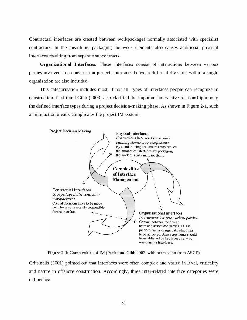
31
Contractual interfaces are created between workpackages normally associated with specialist
contractors. In the meantime, packaging the work elements also causes additional physical
interfaces resulting from separate subcontracts.
Organizational Interfaces: These interfaces consist of interactions between various
parties involved in a construction project. Interfaces between different divisions within a single
organization are also included.
This categorization includes most, if not all, types of interfaces people can recognize in
construction. Pavitt and Gibb (2003) also clarified the important interactive relationship among
the defined interface types during a project decision-making phase. As shown in Figure 2-1, such
an interaction greatly complicates the project IM system.
Figure 2-1: Complexities of IM (Pavitt and Gibb 2003, with permission from ASCE)
Critsinelis (2001) pointed out that interfaces were often complex and varied in level, criticality
and nature in offshore construction. Accordingly, three inter-related interface categories were
defined as:
32
Intrinsic Interface: “Related to the physical links existing in an established production
system concept among the various components.” Based on such a description, the intrinsic
interface appears closely equivalent to the above-introduced physical interface.
Discipline Interface: “Related to the areas of knowledge necessary to engineer and
develop studies, analyses, designs, investigations and developments sufficient and necessary for
the concept, and detailed engineering of the production system and its components.” Without this
description, the term “discipline interface” creates confusion. It may be regarded as a general
interface among disciplines (or trades), which does not remain at the knowledge level.
Project Interface: “Driven by the contracting strategy, existing among contractors,
subcontractors, vendors and any external provider, with regard to their scope of work, schedule
and responsibilities.” According to the description, this category may be equal to the afore-
mentioned contractual interface.
Laan et al. (2000) revealed that interfaces of a transport infrastructure project can be
identified as completely as possible by viewing the system from three perspectives, which lead to
three decompositions: 1) functional decomposition, 2) physical decomposition, and 3) the top-
level requirement decomposition. The physical decomposition helps identify physical interfaces.
The top-level requirement decomposition facilitates the representation of organizational
interfaces because relevant requirements are located to the organizational segments. The
functional decomposition generates a new concept—the functional interface. This interface is not
defined in the two categorizations previously mentioned.
Functional Interface: According to Laan et al. (2000), the functional decomposition is the
decomposition of functions necessary for the performance of the main function; then relations
between the sub-functions are the functional interfaces. It is further stated that the sub-functions
are allocated to the responsible organizational segments. Thus the functional interfaces also
contain contractual interfaces when sub-functions are grouped into separate workpackages and
subcontracted out. In addition, when defining the responsibilities allocated to the “operator”
contract and the “systems” contract, Laan et al. (2000) indicated that “these have the character of
functional interfaces, as they consist of the functional requirements for the infrastructure, and the
restrictions of the infrastructure upon the operators.” This description includes functional

33
requirements presented by one system upon another system (systems performance requirements)
into the functional interfaces. This conceptual extension greatly contributes to housing research
because incorporating systems’ functional requirements into IM consideration will lead to the
improvement of the whole house performance.
According to the above discussions, different perspectives that are used to decompose a
project vary the interface types to be defined. Pavitt and Gibb (2003) decompose the project into
workpackages based on “Work Breakdown Structure (WBS).” Contractual interfaces are thus
defined as grouped specialist contractor workpackages. Laan et al. (2000) decompose the project
based on functions and then invent the functional interfaces. Some researchers think that the
functional decomposition method is superior to the traditional WBS method. Their arguments
will be discussed later in this chapter.
In both research and practice, it is hard for people to follow the strict and complete
interface categorization when they approach interface issues. They often recognize where
interface issues usually occur and then start from there for improvement. Such scattered
improvements make some progress in IM. But the overall project performance remains poor
because of other unattended interface issues. In the following subsections, individual IM
approaches are reviewed, most of which comprise an identification of interface issues as well as
their potential causes. This information helps in understanding the nature and characteristics of
interfaces and reveals the most common interface issues in construction.
2.4.2 Physical Interfaces between Building Components
In the building construction industry, physical interface issues have led to frequent assembly
conflicts that severely delayed the project schedule and compromised long term performance as
well. As a result, researchers have shown growing interest in studying and solving physical
interface issues. Among all research efforts that have been made, two representative works that
focus on how to record and utilize physical interface information are reviewed.
2.4.2.1 CladdISS for Windows and Cladding System
Led by Alistair Gibb, a team at Loughborough University carried out CladdISS, a U.K.
government funded research project aimed to develop standardized interface strategies for the
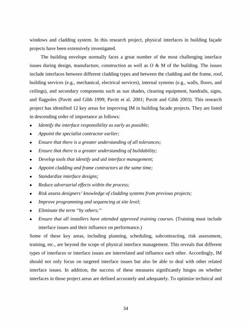
34
windows and cladding system. In this research project, physical interfaces in building façade
projects have been extensively investigated.
The building envelope normally faces a great number of the most challenging interface
issues during design, manufacture, construction as well as O & M of the building. The issues
include interfaces between different cladding types and between the cladding and the frame, roof,
building services (e.g., mechanical, electrical services), internal systems (e.g., walls, floors, and
ceilings), and secondary components such as sun shades, cleaning equipment, handrails, signs,
and flagpoles (Pavitt and Gibb 1999; Pavitt et al. 2001; Pavitt and Gibb 2003). This research
project has identified 12 key areas for improving IM in building facade projects. They are listed
in descending order of importance as follows:
Identify the interface responsibility as early as possible;
Appoint the specialist contractor earlier;
Ensure that there is a greater understanding of all tolerances;
Ensure that there is a greater understanding of buildability;
Develop tools that identify and aid interface management;
Appoint cladding and frame contractors at the same time;
Standardize interface designs;
Reduce adversarial effects within the process;
Risk assess designers’ knowledge of cladding systems from previous projects;
Improve programming and sequencing at site level;
Eliminate the term “by others;”
Ensure that all installers have attended approved training courses. (Training must include
interface issues and their influence on performance.)
Some of these key areas, including planning, scheduling, subcontracting, risk assessment,
training, etc., are beyond the scope of physical interface management. This reveals that different
types of interfaces or interface issues are interrelated and influence each other. Accordingly, IM
should not only focus on targeted interface issues but also be able to deal with other related
interface issues. In addition, the success of these measures significantly hinges on whether
interfaces in those project areas are defined accurately and adequately. To optimize technical and
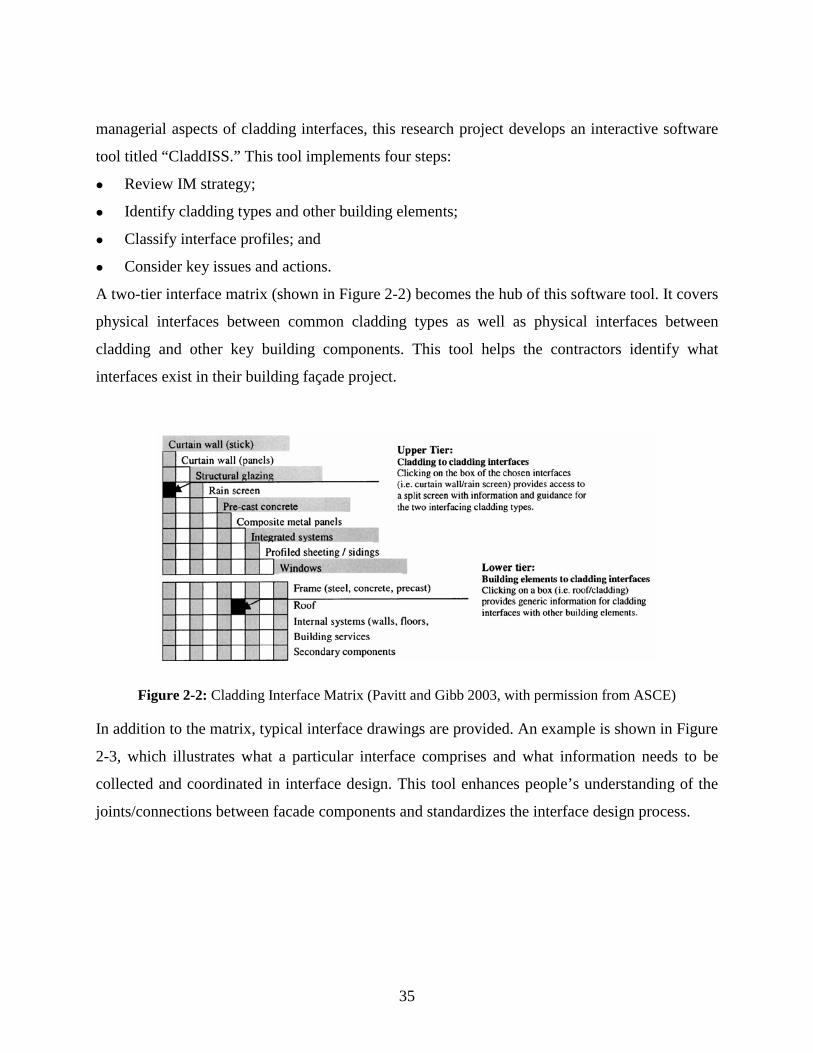
35
managerial aspects of cladding interfaces, this research project develops an interactive software
tool titled “CladdISS.” This tool implements four steps:
Review IM strategy;
Identify cladding types and other building elements;
Classify interface profiles; and
Consider key issues and actions.
A two-tier interface matrix (shown in Figure 2-2) becomes the hub of this software tool. It covers
physical interfaces between common cladding types as well as physical interfaces between
cladding and other key building components. This tool helps the contractors identify what
interfaces exist in their building façade project.
Figure 2-2: Cladding Interface Matrix (Pavitt and Gibb 2003, with permission from ASCE)
In addition to the matrix, typical interface drawings are provided. An example is shown in Figure
2-3, which illustrates what a particular interface comprises and what information needs to be
collected and coordinated in interface design. This tool enhances people’s understanding of the
joints/connections between facade components and standardizes the interface design process.
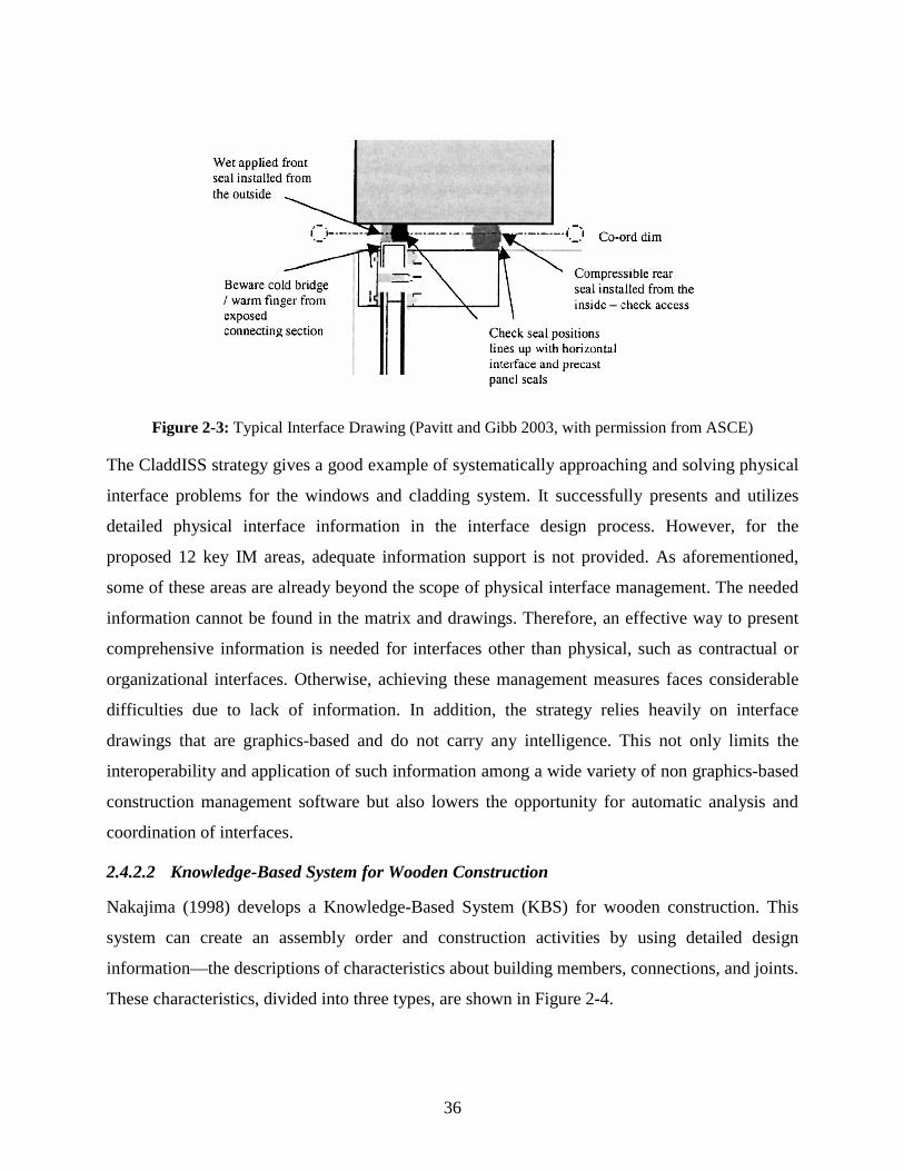
36
Figure 2-3: Typical Interface Drawing (Pavitt and Gibb 2003, with permission from ASCE)
The CladdISS strategy gives a good example of systematically approaching and solving physical
interface problems for the windows and cladding system. It successfully presents and utilizes
detailed physical interface information in the interface design process. However, for the
proposed 12 key IM areas, adequate information support is not provided. As aforementioned,
some of these areas are already beyond the scope of physical interface management. The needed
information cannot be found in the matrix and drawings. Therefore, an effective way to present
comprehensive information is needed for interfaces other than physical, such as contractual or
organizational interfaces. Otherwise, achieving these management measures faces considerable
difficulties due to lack of information. In addition, the strategy relies heavily on interface
drawings that are graphics-based and do not carry any intelligence. This not only limits the
interoperability and application of such information among a wide variety of non graphics-based
construction management software but also lowers the opportunity for automatic analysis and
coordination of interfaces.
2.4.2.2 Knowledge-Based System for Wooden Construction
Nakajima (1998) develops a Knowledge-Based System (KBS) for wooden construction. This
system can create an assembly order and construction activities by using detailed design
information—the descriptions of characteristics about building members, connections, and joints.
These characteristics, divided into three types, are shown in Figure 2-4.

37
Figure 2-4: Characteristics of a Building Construction System (Nakajima 1998, with permission from Blackwell Publishing)
Some of these characteristics such as spatial relationship, joint position in connection surface,
and direction of assembly are closely related to the assembly order. Other characteristics such as
shape of member, shape of cross section, and shape of joint are related to the processing and
fabrication activities. A building construction system, in Nakajima’s view, is composed of units,
each of which is defined as a single structure consisting of two members and one joint. Therefore,
based on the descriptions of characteristics for those members and joints, the assembly order and
construction activities for a building construction system can be determined.
In this research work, detailed characteristics of a joint were carefully studied and rules for
generating the assembly order and activity procedures were summarized. Eventually, a
construction schedule could be determined. This work provides an accurate way of presenting
physical interfaces by focusing on the characteristics of building members, connections, and
joints. The approach is useful for presenting simple physical interface information; but its ability
to handle complex physical interfaces is unknown.
The example that Nakajima used to demonstrate KBS is fabricating wood building
members manually and installing them piece-by-piece. This is a traditional way for housing
construction where usually simple and single joint exists between two building members. Such a
joint can be easily modeled by using the above approach. Nevertheless, current housing
construction has already extensively used manufactured building components, such as roof

38
trusses and floor trusses. In order to minimize the on-site labor requirement, some components
are pre-assembled into larger components in the factory, e.g., a panelized wall. Sometimes,
interrelated building components have even been integrated as complex systems (e.g., an
integrated wall system in modular construction) before they are shipped to the job site. As a
result, on-site connection of those components or systems becomes a complex process and
multiple types of joints or interactions are involved. Under these circumstances, the construction
methods and assembly procedures are distinctive. Nakajima’s approach is unable to model and
handle such complex interrelationships or interactions between building members. Research
works taking into account up-to-date construction innovations should be provided.
2.4.3 Interfaces among Various Construction Parties
A construction project involves many participants. The multitude of project participants causes a
large number of interfaces between them. Al-Hammad and other researchers have conducted
extensive research about interface problems among various construction parties in Saudi Arabia.
Their papers mainly discuss interface relationships between two parties, such as owners and
contractors (Al-Hammad 1990), designers and contractors (Al-Hammad and Assaf 1992; Al-
Mansouri 1998), GCs and subcontractors (Al-Hammad 1993; Hinze and Andres 1994), owners
and maintenance contractors (Al-Hammad 1995), and owners and designers (Al-Hammad and
Al-Hammad 1996).
In a conclusive paper, Al-Hammad (2000) identifies 19 main interface problems among
various construction parties. These problems have been classified into four categories: financial
problems, inadequate contract and specification, environmental problems, and other common
problems. Strictly speaking, these problems (shown in Table 2-2) are not interface issues this
research defines, but more likely reasons or factors causing various interface issues. As listed
below, “insufficient work drawing details” may lead to assembly difficulties, errors, or conflicts
between two building components. “Delay in progress payment by owner” may incur a poor
working relationship as well as suspension of work in a project.

39
Table 2-2: Common Interface Problems from Construction Parties’ Viewpoint (Al-Hammad 2000, with permission from ASCE)
A survey has identified the severity of these problems to the inter-party relationship. As shown in
the table, among individual interface problems, “violating conditions of the contract” is ranked
the highest. However, among four interface problem categories, “financial problems” has the
severest impact on working relationships. This is because at the current stage project profit is still
the final goal of most project participants. Besides interface problems listed in the questionnaire,
the following issues including long lead items, approval permits, shop drawing approval,
material procurement, and lack of designer experience have been added by survey respondents.
Under most circumstances, a construction project has a single GC, who subcontracts out
the specialty construction work and manages subcontractors and interfaces between them and
their work. For financial, schedule, or jobsite control reasons, an owner may sometimes enter
into multiple construction contracts directly with trade subcontractors. Creating more
complicated inter-party interfaces, this type of contracting method is very likely to lead to project
budget and schedule overruns without proper pre-planning and execution. Kuprenas and Rosson
40
(2000) identify that questions of responsibility for contractors and disagreements about scopes of
work are common problems. Interfaces between two trade contractors should be defined and
clarified with respect to scope and responsibilities in the bid division descriptions. This can clear
up future confusion about the ownership of such interfaces. Simultaneously, additional contracts
may be required to pick up items omitted from trade contracts or missing items about interfaces.
Shrive (1992) points out that the key for the successful delivery of such projects should be
preplanning of scopes and responsibilities for the whole work and consideration of all contract
interfaces before bidding.
2.4.4 Design-Construction Interface
The design-construction interface is another area drawing considerable research interest. Studies
in manufacturing have shown that management of the interface between design and
manufacturing is very important for achieving a higher level of manufacturing flexibility (Shirley
1987). In construction, enhancing management of the design-construction interface improves
both design and construction.
The improvement of the design process becomes critical for ameliorating the design-
construction interface. During the design phase, customer requirements, constructive
considerations, and quality standards are defined and incorporated into construction drawings
and technical specifications to guide construction activities. In practice, this important phase is
conducted with little interaction between the design and construction teams, which leads to
problems such as incomplete designs, lack of constructability, design errors, change orders,
rework, construction delays, and waste (Alarcón and Mardones 1998). According to Fritschi
(2002/03), in the design phase, causes of interface issues fall into four main groups: 1) no clear
definition of tasks, 2) insufficient preparation work, 3) unsatisfactory information, and 4) poor
communication.
Alarcón and Mardones (1998) consider design a flow within which inspection, moving,
transformation and waiting for information, redesign due to errors, omissions, and uncertainty,
etc. are all waste. Improvement and optimization of the design process can avoid value losses.
The main design problems identified include poor design quality, lack of design standards, lack
of constructability, and lack of coordination among specialties. In their research, a “House of
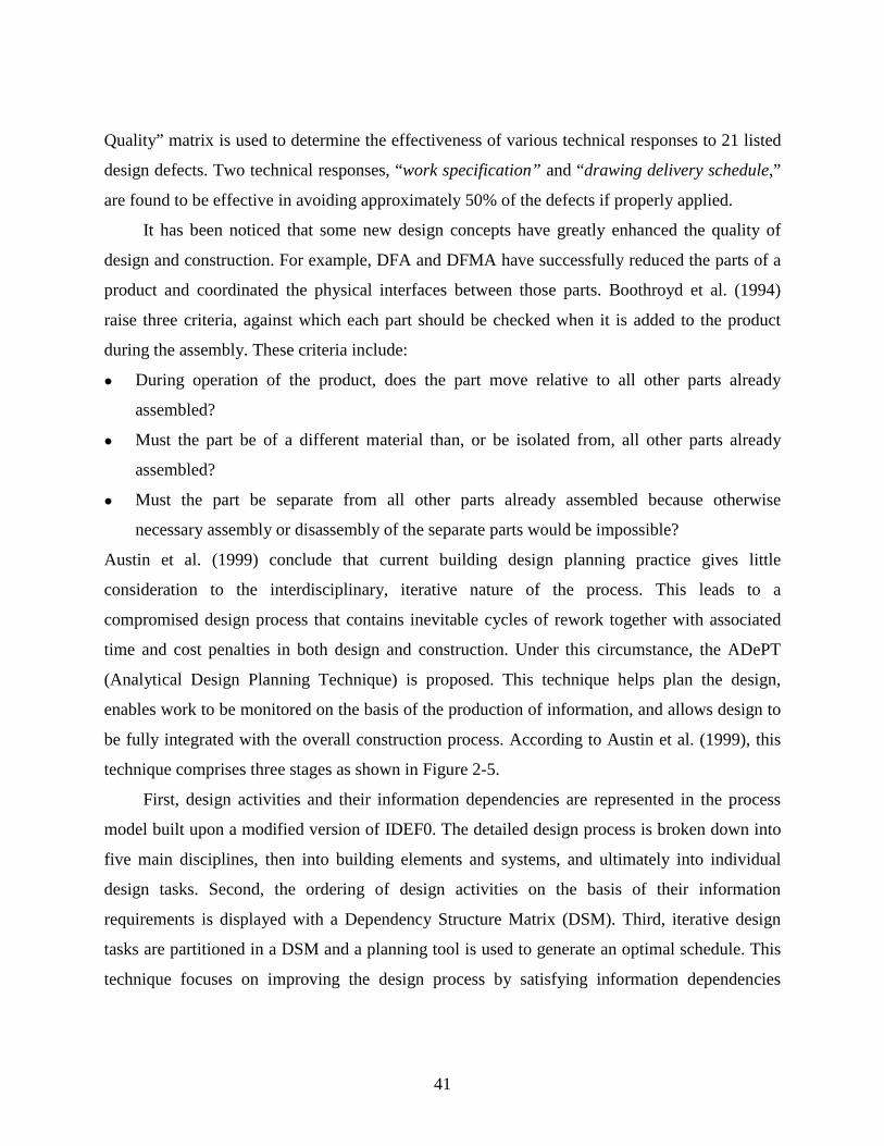
41
Quality” matrix is used to determine the effectiveness of various technical responses to 21 listed
design defects. Two technical responses, “work specification” and “drawing delivery schedule,”
are found to be effective in avoiding approximately 50% of the defects if properly applied.
It has been noticed that some new design concepts have greatly enhanced the quality of
design and construction. For example, DFA and DFMA have successfully reduced the parts of a
product and coordinated the physical interfaces between those parts. Boothroyd et al. (1994)
raise three criteria, against which each part should be checked when it is added to the product
during the assembly. These criteria include:
During operation of the product, does the part move relative to all other parts already
assembled?
Must the part be of a different material than, or be isolated from, all other parts already
assembled?
Must the part be separate from all other parts already assembled because otherwise
necessary assembly or disassembly of the separate parts would be impossible?
Austin et al. (1999) conclude that current building design planning practice gives little
consideration to the interdisciplinary, iterative nature of the process. This leads to a
compromised design process that contains inevitable cycles of rework together with associated
time and cost penalties in both design and construction. Under this circumstance, the ADePT
(Analytical Design Planning Technique) is proposed. This technique helps plan the design,
enables work to be monitored on the basis of the production of information, and allows design to
be fully integrated with the overall construction process. According to Austin et al. (1999), this
technique comprises three stages as shown in Figure 2-5.
First, design activities and their information dependencies are represented in the process
model built upon a modified version of IDEF0. The detailed design process is broken down into
five main disciplines, then into building elements and systems, and ultimately into individual
design tasks. Second, the ordering of design activities on the basis of their information
requirements is displayed with a Dependency Structure Matrix (DSM). Third, iterative design
tasks are partitioned in a DSM and a planning tool is used to generate an optimal schedule. This
technique focuses on improving the design process by satisfying information dependencies

42
among design activities in a more efficient way. It may be limited to projects where aesthetic
value is minimal in design considerations.
Figure 2-5: Analytical Design Planning Technique (AdePT) (Austin et al. 1999, with permission from Thomas Telford Ltd)
Other researchers have also made similar attempts to improve the design process. For instance,
Chua et al. (2003) proposes a Process-Parameter-Interface (PPI) model to manage the design
process of Architecture, Engineering, and Construction (AEC) projects. The model aims to
improve design process scheduling by reducing information iterative loop and to enhance
efficient collaboration. All research introduced above considers only activities purely related to
the design development.
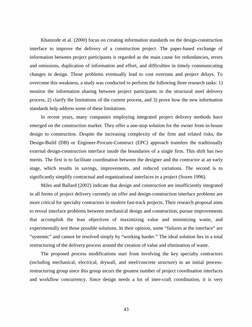
43
Khanzode et al. (2000) focus on creating information standards on the design-construction
interface to improve the delivery of a construction project. The paper-based exchange of
information between project participants is regarded as the main cause for redundancies, errors
and omissions, duplication of information and effort, and difficulties in timely communicating
changes in design. Those problems eventually lead to cost overruns and project delays. To
overcome this weakness, a study was conducted to perform the following three research tasks: 1)
monitor the information sharing between project participants in the structural steel delivery
process, 2) clarify the limitations of the current process, and 3) prove how the new information
standards help address some of these limitations.
In recent years, many companies employing integrated project delivery methods have
emerged on the construction market. They offer a one-stop solution for the owner from in-house
design to construction. Despite the increasing complexity of the firm and related risks, the
Design-Build (DB) or Engineer-Procure-Construct (EPC) approach transfers the traditionally
external design-construction interface inside the boundaries of a single firm. This shift has two
merits. The first is to facilitate coordination between the designer and the contractor at an early
stage, which results in savings, improvements, and reduced variations. The second is to
significantly simplify contractual and organizational interfaces in a project (Sozen 1996).
Miles and Ballard (2002) indicate that design and construction are insufficiently integrated
in all forms of project delivery currently on offer and design-construction interface problems are
more critical for specialty contractors in modern fast-track projects. Their research proposal aims
to reveal interface problems between mechanical design and construction, pursue improvements
that accomplish the lean objectives of maximizing value and minimizing waste, and
experimentally test those possible solutions. In their opinion, some “failures at the interface” are
“systemic” and cannot be resolved simply by “working harder.” The ideal solution lies in a total
restructuring of the delivery process around the creation of value and elimination of waste.
The proposed process modifications start from involving the key specialty contractors
(including mechanical, electrical, drywall, and steel/concrete structure) in an initial process-
restructuring group since this group incurs the greatest number of project coordination interfaces
and workflow concurrency. Since design needs a lot of inter-craft coordination, it is very
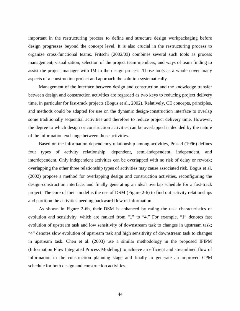
44
important in the restructuring process to define and structure design workpackaging before
design progresses beyond the concept level. It is also crucial in the restructuring process to
organize cross-functional teams. Fritschi (2002/03) combines several such tools as process
management, visualization, selection of the project team members, and ways of team finding to
assist the project manager with IM in the design process. Those tools as a whole cover many
aspects of a construction project and approach the solution systematically.
Management of the interface between design and construction and the knowledge transfer
between design and construction activities are regarded as two keys to reducing project delivery
time, in particular for fast-track projects (Bogus et al., 2002). Relatively, CE concepts, principles,
and methods could be adapted for use on the dynamic design-construction interface to overlap
some traditionally sequential activities and therefore to reduce project delivery time. However,
the degree to which design or construction activities can be overlapped is decided by the nature
of the information exchange between those activities.
Based on the information dependency relationship among activities, Prasad (1996) defines
four types of activity relationship: dependent, semi-independent, independent, and
interdependent. Only independent activities can be overlapped with no risk of delay or rework;
overlapping the other three relationship types of activities may cause associated risk. Bogus et al.
(2002) propose a method for overlapping design and construction activities, reconfiguring the
design-construction interface, and finally generating an ideal overlap schedule for a fast-track
project. The core of their model is the use of DSM (Figure 2-6) to find out activity relationships
and partition the activities needing backward flow of information.
As shown in Figure 2-6b, their DSM is enhanced by rating the task characteristics of
evolution and sensitivity, which are ranked from “1” to “4.” For example, “1” denotes fast
evolution of upstream task and low sensitivity of downstream task to changes in upstream task;
“4” denotes slow evolution of upstream task and high sensitivity of downstream task to changes
in upstream task. Chen et al. (2003) use a similar methodology in the proposed IFIPM
(Information Flow Integrated Process Modeling) to achieve an efficient and streamlined flow of
information in the construction planning stage and finally to generate an improved CPM
schedule for both design and construction activities.

45
a b
Figure 2-6: a) Partitioned Design Structure Matrix; b) Modified Information Matrix (Bogus et al. 2002, with permission from ASCE)
2.4.5 Contractual Interface
One of the widely employed forms of work structuring is WBS, which divides a project into
elements according to customary contracting and craft divisions. The 16 CSI (Construction
Specification Institute) divisions (including sitework, concrete, metals, wood and plastics, etc.)
provide a common method of classification for WBS. Based on a defined WBS, distinguished
work scopes are separately awarded to different subcontractors who are responsible for the
delivery of such elements as foundations, masonry, pre-cast concrete walls, windows and doors,
and insulation. Actually, the assumptions behind WBS may not be realistic because work scope
is not divisible into independent elements. Project elements are commonly interdependent,
according to Ballard et al. (2001). For example, external masonry walls and windows are closely
interrelated since the windows have to be embedded into the external walls. However, in practice,
they are usually subcontracted out to different contractors.
Miles and Ballard (2002) critique the traditional WBS. From their point of view, facilities
are composed of subsystems and functionalities that have crossed traditional contract and craft
boundaries. Successful performance of a subsystem design and construction normally involves a
team of players. As an example, the building enclosure/envelope is one of the typical building
subsystems. It consists of many interdependent components (e.g., roof, masonry wall, windows,
insulation, waterproofing), which are produced and installed by different craft trades. The
construction quality and the future performance of the building envelope are determined by
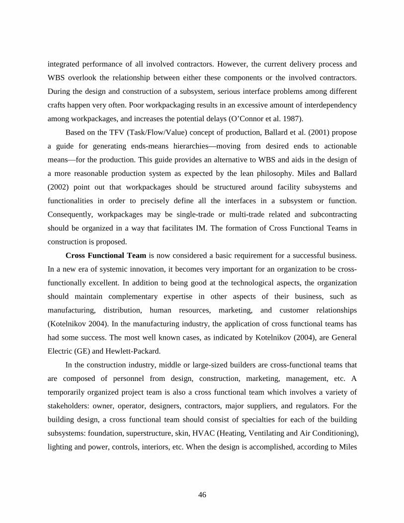
46
integrated performance of all involved contractors. However, the current delivery process and
WBS overlook the relationship between either these components or the involved contractors.
During the design and construction of a subsystem, serious interface problems among different
crafts happen very often. Poor workpackaging results in an excessive amount of interdependency
among workpackages, and increases the potential delays (O’Connor et al. 1987).
Based on the TFV (Task/Flow/Value) concept of production, Ballard et al. (2001) propose
a guide for generating ends-means hierarchies—moving from desired ends to actionable
means—for the production. This guide provides an alternative to WBS and aids in the design of
a more reasonable production system as expected by the lean philosophy. Miles and Ballard
(2002) point out that workpackages should be structured around facility subsystems and
functionalities in order to precisely define all the interfaces in a subsystem or function.
Consequently, workpackages may be single-trade or multi-trade related and subcontracting
should be organized in a way that facilitates IM. The formation of Cross Functional Teams in
construction is proposed.
Cross Functional Team is now considered a basic requirement for a successful business.
In a new era of systemic innovation, it becomes very important for an organization to be cross-
functionally excellent. In addition to being good at the technological aspects, the organization
should maintain complementary expertise in other aspects of their business, such as
manufacturing, distribution, human resources, marketing, and customer relationships
(Kotelnikov 2004). In the manufacturing industry, the application of cross functional teams has
had some success. The most well known cases, as indicated by Kotelnikov (2004), are General
Electric (GE) and Hewlett-Packard.
In the construction industry, middle or large-sized builders are cross-functional teams that
are composed of personnel from design, construction, marketing, management, etc. A
temporarily organized project team is also a cross functional team which involves a variety of
stakeholders: owner, operator, designers, contractors, major suppliers, and regulators. For the
building design, a cross functional team should consist of specialties for each of the building
subsystems: foundation, superstructure, skin, HVAC (Heating, Ventilating and Air Conditioning),
lighting and power, controls, interiors, etc. When the design is accomplished, according to Miles
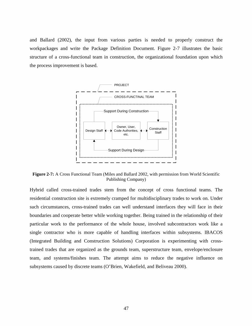
47
and Ballard (2002), the input from various parties is needed to properly construct the
workpackages and write the Package Definition Document. Figure 2-7 illustrates the basic
structure of a cross-functional team in construction, the organizational foundation upon which
the process improvement is based.
Design StaffOwner, User,
Code Authorities, etc.
Construction Staff
Support During Construction
Support During Design
CROSS-FUNCTINAL TEAM
PROJECT
Figure 2-7: A Cross Functional Team (Miles and Ballard 2002, with permission from World Scientific Publishing Company)
Hybrid called cross-trained trades stem from the concept of cross functional teams. The
residential construction site is extremely cramped for multidisciplinary trades to work on. Under
such circumstances, cross-trained trades can well understand interfaces they will face in their
boundaries and cooperate better while working together. Being trained in the relationship of their
particular work to the performance of the whole house, involved subcontractors work like a
single contractor who is more capable of handling interfaces within subsystems. IBACOS
(Integrated Building and Construction Solutions) Corporation is experimenting with cross-
trained trades that are organized as the grounds team, superstructure team, envelope/enclosure
team, and systems/finishes team. The attempt aims to reduce the negative influence on
subsystems caused by discrete teams (O’Brien, Wakefield, and Beliveau 2000).

48
2.4.6 Systems Approaches
In the literature, systems approaches such as the “building systems” and “systems integration”
have been employed in construction. These approaches are related to the interface issues and IM.
2.4.6.1 Systems Engineering
Diverse systems approaches employed in different industry domains usually originated from
systems engineering (also called systems design engineering), which was initiated around the
time of World War II when large or highly complex engineering projects, e.g., the development
of a new airliner or warship, were often broken down into stages and managed throughout the
entire life of the product or system (from concept, design, production, operation to disposal).
There, interface design and specification were required to enable the pieces of the system to
interoperate.
Systems engineering can be defined as “the application of engineering to solutions of a
complete problem in its full environment by systematic assembly and matching of parts in the
context of the lifetime use of the system” (http://www.ichnet.org/glossary.htm). Applied in
offshore construction, systems engineering represents an interdisciplinary approach and means to
enable the realization of successful systems. It focuses on defining customer needs and required
functionality early in the development cycle, documenting requirements, and then proceeding
with design synthesis and system validation while considering the complete problem: operations,
performance, test, manufacturing, cost and schedule, training and support, and disposal. Systems
engineering integrates all the disciplines and specialty groups into a team effort that forms a
structured development process (INCOSE 2004). In what follows, several systems engineering
applications are reviewed and their close relationship with IM is depicted.
2.4.6.2 Systems Engineering Approach for Dynamic IM
In construction, interface coordinators or interface managers may be appointed to handle
interface issues. Their experience and performance make big differences in the project outcome.
With the increasing complexity of construction projects, those personnel’s performance
fluctuates.

49
The systems engineering method has been applied to managing interfaces of a transport
infrastructure project in Netherlands. According to Laan et al. (2000), the project was complex
both in size and in the number of internal and external interfaces. There were seven large
Design-Construction contracts for the civil sub-structure and connections with the existing
infrastructure, one Design-Build-Finance-Maintain contract for the rail systems, and a public
tendered contract with a Train Operation Company. The complexity of this project made IM
there a very challenging task.
After studying the complicated relationships between those contracts and their products or
services, Laan et al. (2000) reached a conclusion; i.e., when a project is built from different
contracts, these contracts have to be integrated based on systems integration and IM must be
established in the contracts in a way that they can work together effectively and efficiently. The
proposed systems engineering approach comprises seven aspects of IM presented below:
Development of a structured specification tree where interface requirements between the
systems are clearly stated;
Scenario analysis;
IM including interface identification, interface definition, and interface verification and
control;
Configuration management;
Risk management;
Verification activities; and
Preparation of the “Systems” contract.
In addition, a series of matrices were used to effectively represent complex interface
relationships including functional interfaces existing between systems contracts. All discovered
interfaces were prioritized based on an overall risk analysis. During the design and construction
phases, interfaces became highly dynamic. The dominant decision criterion for interface
management and control was based on the system functionality. In the end, it was indicated that
this case also showed that systems engineering principles and methods had to be employed
flexibly according to the needs of the project and the environment (including the culture).

50
2.4.6.3 Building Systems
“Building Systems” is an approach to industrializing the building process by using the basic
problem solving strategy of the general systems theory. It was adopted in the 1950s and 1960s.
According to Sullivan (1980), the general systems strategy starts with the analysis of a particular
system, or situation, in terms of the “whole,” and then works toward the specific considerations
of the “particular” parts. For example, the whole building system consists of many components
and segments that represent a set of related tasks. The physical system itself is only one
component within a larger and more complex process. The development of such a physical
system within the context of the holistic understanding of that larger system or process
constitutes the “systems approach.”
In a building system, individual manufacturers supply a number of interactive subsystems
(structure, atmosphere, vertical skin, plumbing, etc.) or components. It becomes very important
for the subcontractors of the interfacing subsystems to cooperatively develop their proposal.
Otherwise, extensive fitting and adjustments in the field will be required. For this reason,
adequate cooperation on the part of independent subsystem bidders must be guaranteed. In
addition, all other tasks including architectural planning, design, scheduling, as well as a
contractual system have to suit the needs of the component manufacturers and subcontractors
(Sullivan 1980).
There were several important systems building approaches in the past, including the
CLASP (Consortium for Local Authority Special Program) system in the U.K., the SCSD
(School Component Systems Development) project in the U.S., and the SEF (Study for
Educational Facilities) project in Canada (Sullivan 1980). In SEF, the interface-oriented bidding
process and subcontracting strategy were first employed to enhance coordination between
interrelated subsystem providers and to minimize incompatibility.
In the systems approach, the extensive use of standardized, interchangeable prefabricated
building components to form subsystems was assumed to help industrialization. But in practice,
four critical interface problems often occurred. First, component systems were often “closed,”
which were difficult for interconnection with systems made by other manufacturers. Second,
separately produced components caused serious problems on dimensional coordination. Third,

51
functional performance was hard to achieve by simple combination of different components. It
was a real challenge for the involved parties to enhance cooperation and coordination during the
phases of design, planning, manufacturing, and construction. Fourth, conventional housing
systems integration considers building subsystems separately. The interrelationship between
different but connective subsystems is ignored. The lack of coordination between subsystems
leads to uninformed design, lack of prototyping, absence of production simulation, and lack of
understanding of the consequences of the field modification on performance (O’Brien,
Wakefield, and Beliveau 2000).
The building systems approach achieved some success in educational building systems
where performance-based and dimensionally coordinated building components were used in an
open system. However, numerous problems still existed and need better solutions. In addition,
this approach was seldom applied in housing construction, which limits its benefits in practice.
2.4.6.4 Systems Integration in Housing Construction
The customer requirements for any product have greatly increased in recent decades. There is no
exception for a built facility (e.g., a building). However, differing from other types of industry
products, the performance of a building is difficult to define and evaluate due to lack of clear
standards and criteria for evaluation. The progress toward improvement in the building
construction industry is slower than that in other industries. To catch up, whole-house research
has been conducted in recent years.
The latest effort toward whole-house design and construction is made by Partnership for
Advancing Technology in Housing (PATH). In the relevant research, “whole-house” design has
been closely linked to the application of “systems engineering” principles. According to PATH
(2003), the house is considered a system “in which specific products, materials and construction
methods that may involve just one part of the house can have impacts throughout the house.”
Therefore, improvement efforts are focused on avoiding negative interactions and capitalizing on
synergies or positive interactions in the design phases.
As indicated before, a building is composed of many subsystems. These subsystems are
physically interrelated; changes to one subsystem influence the performance of many other
subsystems. The practice in systems integration in housing still mainly considers each major

52
building subsystem separately. Recently, researchers began to discuss a high level of integration,
a real “optimization.” In the funded HUD project “Industrializing the Residential Construction
Site” conducted at Virginia Tech, systems integration was considered one of the most important
means to enhance industrialization. Five primary areas interdependent in practice were defined.
Their influence on housing construction is presented as follows (O’Brien, Wakefield, and
Beliveau 2000):
Information integration: Making the many pieces of information used by homebuilders
accessible as one data source
Physical integration: Making the many parts fit together as one
Performance integration: Making the many systems perform as one
Production integration: Conducting the many processes as one
Operation integration: Operating the many subsystems as one
Systems integration can greatly increase the number of interfaces to be considered in the design,
construction, and operation stages. Except physical interfaces that have been considered by the
industry, other interfaces such as performance and operational interfaces are totally new concepts
to the industry. This raises the complexity of interface issues in construction and makes them
difficult to manage and control. Without clearly defining the newly emerging interfaces and their
influence, the industry does not know where such interfaces exist and how to manage them based
on certain rules.
“Optimization” across subsystems is complex in many aspects. The PATH research points
out that “optimization” needs a series of performance metrics for each subsystem, a
mathematical understanding of their relationships, and the ability to convert these performance
metrics into economic terms. In addition, the approach must also be compatible with involved
specialized product manufacturers and construction trades. The PATH roadmap, therefore,
defines the whole-house design as follows (PATH 2003):
Integrating various subsystems or components to optimize design and operation
Integrating functions of various components or subsystems in a home
Modifying the management approach and/or other processes to simplify the schedule,
reduce negative interdependencies, and simplify construction

53
Expanding the use of factory-built assemblies including whole-building systems.
2.5 INFORMATION MODELING FOR INTERFACES AND IM
IT (Information Technology) can work as a facilitator for IM, especially in complex building
projects. Accurate information modeling is very important in the process of applying advanced
technologies to the creation, management, and use of interface information. Existing information
modeling methods have achieved some success in modeling interface information. However, the
limitations of those methods have largely restricted the applications of the modeled information.
2.5.1 3D/4D Visualization
IT applications, in particular 3D/4D visualization techniques, are helpful for avoiding and
resolving interface problems. Visualization helps not only knowledge discovery in construction
but also helps the designer examine and understand the interrelationship between design
parameters, especially in the multi-disciplinary environment (Rafiq 2003). Better visualization
makes it possible to quickly test appearances and consistency of dimensions. 3D construction
models aim to help the contractor put a project together and foresee interface conflicts before
they happen on the jobsite.
4D technologies combine 3D CAD models with construction activities to analyze and
visualize many aspects of a construction project, from the 3D design of a project to the sequence
of construction to the relationships among schedule, cost and resource available. The underlying
3D model and schedule model are based on object-oriented concepts; the users can query their
content and relationships (Emerging Construction Technologies 2000). The objective of 3D/4D
visualization is to verify constructability and reveal schedule conflicts (Danso-Amoako et al.
2003).
Contractors usually have difficulties in coordinating 2D drawings from each specialty to
minimize or eliminate conflicts on the jobsite. Such 2D drawings do not contain visualized
information. They also contain no required intelligence and analysis environment to support the
rapid and integrated design and construction of facilities. In contrast, 3D/4D visualization
facilitates the understanding of the relationship between production elements and various

54
construction activities, and therefore helps improve activity sequencing, constructability, and
workflow for subcontractors (Emerging Construction Technologies 2000).
Danso-Amoako et al. (2003) propose a framework for the development of a point-n-click
interface for construction visualization focusing more on how pieces and components fit together
(i.e., constructability) rather than schedule conflicts. This interface is a browser-like and user-
friendly environment where users just click, point, drag, mouse-over, etc. A global view of the
proposed interface system consists of the following processes:
User request;
Query from proposed engine to a standard CAD package;
CAD package response to query; and
Proposed engine’s response to user interface (browser)
Nevertheless, 3D/4D CAD is still not effectively employed in practice due to some barriers.
Danso-Amoako et al. (2003) examine the concept of 3D/4D CAD computer visualization and
analyze some of the most likely reasons for this anomaly. First of all, one major problem in
migrating from 2D to 3D construction visualization is how to determine the level of detail to be
shown in the model. Apparently, the GC and subcontractors request detail at different levels.
Second, the lack of industry level standardization causes problems. 4D models are built in an ad
hoc manner without a methodology guiding their generation. Third, the transfer efficiency
between 2D drawings to 3D modeling production is low. Fourth, it still remains unclear about
how 3D models can be properly used on the jobsite since 3D models are normally available only
for the single-user desktop environment (Danso-Amoako et al. 2003; Emerging Construction
Technologies 2000).
2.5.2 Object-Oriented CAD and Supporting Modeling Methods
It is difficult for a single design company or contractor to support any significant software
development except a common software basis to be used for different applications (Serén et al.
1993). Although Computer Aided Design (CAD) has been widely accepted and employed in the
industry since the 1980s, its applications are still restricted to generating 2D or 3D architectural
and constructional drawings. 2D drawings are composed of lines and shapes without any
intelligence about what the lines and shapes represent. 3D geometric models include shapes,

55
lines and points, and three-dimensional components. Although making building objects more
visible, 3D models do not carry intelligence about other properties of these objects (Jonathan
Cohen and Associates 2004). As a result, comprehensive and efficient coordination via computer
programming is impossible.
In practice, the most acceptable format for information transmission is paper-based. 2D
blueprints are exchanged between different parties and used on the jobsite. With the development
of Internet technology for sharing data digitally in the 1990s, CAD drawings can now be easily
shared electronically. However, the lack of a shared project model still limits the usage of such
electronic drawings that do not carry more information than the paper-based version. For
example, specialty subcontractors, who conduct detailing design on their scopes of work,
normally generate their own shop drawings (for fabrication and installation) based on the paper
drawings or electronic drawings they received. They have to request further information from
architects and other contractors for their detailed design since the information carried by CAD
files is very limited.
Object-oriented CAD is a new idea for modeling physical objects such as building
components. Specifically, these components are represented as objects containing the physical
geometry as well as many other kinds of attributes including shape, behavior, code and
performance data, transport requirements, cost, information related to construction means,
methods and schedule, maintenance, and facilities management (Jonathan Cohen and Associates
2004). Object-oriented CAD facilitates the generation of a shared project model to which
participants would have real-time access throughout the life of the project and can contribute
their own knowledge while using information supplied by others. There are some successful
applications, such as ArchiCAD and DDSPartner by Graphisoft, based on an object-oriented
CAD system. These applications aim to achieve intelligent data exchange between architecture
building models and building services.
Several modeling methods are used to implement the function of object-oriented CAD.
Jonathan Cohen and Associates (2004) describes the following three models:
Parametric model: It visualizes the relationship between building elements. When a
variable is changed, its influence on related elements is seen by automatically regenerating the

56
model. The model is constantly responsive to changes and offers a degree of flexibility and
coordination previously unavailable.
Procedural model: It adds some special ability to the model. For example, the model can
prevent incompatible elements from being placed adjacent to each other.
Generative model: It creates geometries that satisfy the requirements and rules set by the
user. These models greatly help interface coordination between building components from
different perspectives.
Currently, there exist two streams for developing an intelligent CAD. One is to give the
system powerful problem-solving ability. This can be achieved by developing a Self Contained
Expert System (SCES). The other is to place the emphasis on understanding the designer’s
intention. Studies have been conducted to find out prerequisite requirements for developing these
two streams (Marghitu et al. 1993; Marghitu et al. 1994). Through studying one of the most
powerful advanced CAD systems—Pro/ENGINEER—solutions for several classes of CAD
problems in the areas of specification, design, assembly, diagnosis, monitoring, control,
debugging, and instruction, were found (Mills et al. 1992).
The possibility of applying the object-oriented approach to the construction industry has
been extensively discussed. Researchers have presented various application tools and models,
such as OOCAD (Object-Oriented CAD) tool, Object-Oriented Product Model, and
OSCONCAD (Open Systems for Construction CAD) model (Scherer and Katranuschkov 1993;
Serén et al. 1993; Marir et al. 1998).
O’Brien, Wakefield, and Beliveau (2000) indicate that the object-oriented CAD tools can
help physical and performance integration by rationalizing all subsystems, i.e., drawing all
required components and finding the most efficient method to connect like-subsystem
components. The program can therefore automatically check for physical collisions between
subsystems. For example, object-oriented CAD-based physical integration tools can be employed
to the interface between adjacent subsystems (e.g., plumbing and framing) during the design
phase. The same position-checking and interference-detection tools can be utilized to verify the
relationships among components and subcomponents of a subsystem. All these applications are

57
greatly helpful for IM in big projects, because as project complexities increase, the consistency
of physical interfaces becomes intractable for an interface coordinator/manager.
However, object-oriented CAD systems remain rooted to building graphics due to their
graphics-based CAD foundations. This creates a limitation that prevents object-oriented CAD
systems from being fully optimized for creating and managing information about a building
(AutoDesk, Inc. 2002). Therefore, the evolution of object-oriented CAD will continue with the
development of building information modeling solutions that add the management of
relationships between building components (AutoDesk, Inc. 2002).
2.5.3 Industry Foundation Classes (IFCs)
Even with many IT tools available, it is still difficult for project participants to effectively
communicate and share information with one another. They should have a common
interpretation of construction design objects. The project specification is a document that
characterizes the products and specifies the processes. However, with the development of various
computer applications assisting design, construction and project management, common
construction objects or management contents may be displayed differently in those computer
applications. “Interoperability,” therefore, becomes very important for the open sharing of
information between different hardware or software applications in use.
Interoperability requires that concepts which are common between different software
applications are understood to be common and declared accordingly (Wix and Liebich 1997).
The International Alliance for Interoperability (IAI), a public organization open to any member
of the building industry, was first formed in 1994 and became a global organization later in 1996.
The IAI aims to specify how the “things” (doors, walls, fans, etc.) that could occur in a building
are represented electronically. The IFC object model has been released to provide an
environment of interoperability among IFC-compliant software applications in the AEC/FM
(Architecture, Engineering, and Construction/Facilities Management) industry. For example, the
CAD and building simulation software can automatically acquire and exchange building
geometry and other building data from project models created with IFC-compliant CAD software
without loss of accuracy (Bazjanac and Crawley 1997). This makes it possible for intelligent
interface-conflict checking programs to work based on existing data.

58
The IFC uses the object modeling terminology, for example, class and object. In the IFC, a
range of things that have common characteristics are called a class, which can be represented by
a specification. Each instance of its use is called an object. The IFC, composed of a series of
specifications, represents a data structure supporting an electronic project model which is useful
in sharing data across applications (IAI 1999a). That is to say, the IFC defines a single, object-
oriented data model of buildings. This data model is the basis for any recommended applications.
IFC-based objects allow AEC/FM professionals to share a project model, yet allow each
profession to define its own view of the objects contained in that model. The subsequent
applications are always able to read and understand the characteristics defined by preceding
professionals and add information to the object. This keeps the data consistent and coordinated
through different applications. Furthermore, the shared data can continue to evolve during the
whole process of a project (IAI 1999a). When other professionals share electronic information
about characteristics and function requirements of an object recorded in IFC-compliant
applications, physical and functional interfaces between building components or subsystems
could be properly coordinated and handled.
Figure 2-8 illustrates the architecture of the IFC object model. There are four conceptual
layers using a strict referencing hierarchy. Those layers are explained as follows:
Resource layer: Resources here can be characterized as general purpose or low level
concepts or objects that do not rely on any other classes in the model for their existence with a
few exceptions. All resources represent individual business concepts (IAI 1999b).
Core layer: There are two components. The kernel provides all the basic concepts required
for IFC models within the scope of the current IFC release and determines the model structure
and decomposition. A set of core extensions provide extensions or specifications of concepts
defined in the Kernel (IAI 1999b). Wix and Liebich (1997) emphasize the importance of the
classification of decomposition strategies since decomposition brings a basic functionality into
the IFC definition. Three categories of decomposition are defined as: functional decomposition,
constructive decomposition, and geometric decomposition. The decomposition methodology for
each category can be effectively explained through examples.

59
Interoperability layer: This layer provides the provision of modules defining concepts or
objects to two or more domain/application models (IAI 1999b).
Domain/Applications layer: Domain/Application models provide further model detail
within the scope requirements for an AEC/FM domain process or a type of application. Each
model is a separate one, such as a model for architecture or a model for HVAC work. All these
models can use or reference any class defined in the Core and Independent Resource layers (IAI
1999b).
Figure 2-8: IFC Object Model Architecture (Wix and Liebich 1997, with permission from CIB)
The IAI (1999a) has set up important representatives of information for the development of the
IFC, such as classes, objects, attributes (information about the class or its interface), relationships
(occurring between classes), interfaces, the object model, process diagrams, usage scenarios, and

60
test cases. These concepts are very useful for this research to accurately define the building
components and find ways to represent interface information.
The IFC object model improves AEC information presentation in product models in many
aspects. For example, it defines model elements, functional roles, and systems separately so that
an element can assume multiple roles and/or be the member of multiple systems. It also allows
applications to capture design intent (space requirements, space adjacency, and connectivity
between elements) and design constraints (coordination of design grids, complex geometric
relationships, alignment with offset, code constraints, etc.). The IFC model and its extension
successfully build a platform that empowers various application developers through access to a
very large constituency of end users and compatible applications (IAI 1999b).
Even though the IFC has established a comprehensive project object model, some
limitations do exist. The latest version IFC2x3 (IFC2x Edition 3) has improved some aspects of
Version 2.0—the previous release. It still maintains the scope of IFC2.0. As a result, discussion
here is mainly based on a review of IFC2.0. For the purpose of this research, two questions are
raised during review of the IFC specification. Are those elements, attributes, relationships, etc.
defined in the IFC capable of modeling all types of interfaces or providing complete interface
information for IM? And, is the IFC providing standardized interface representation for the use
of multi-disciplines or a variety of project participants?
IFC2.0 itself states limitations for some key object model concepts, some of which are
related to interfaces. For instance, IFC2.0 only supports point connections for connections
between model elements. It is said that future release would add connections at edges and
surfaces. Another example is that IFC2.0 defines relationships between IFC objects. But the
relationship types are very limited. Only five categories are defined so far: containment (both
physical and conceptual), grouping, connectivity, constraint, and resource. Although the IFC
provides an environment of interoperability for information in a building and a building project,
its capability of modeling multiple types of interfaces is poor. Therefore, this research proposes a
completely new way of interface modeling by defining interfaces as distinct objects instead of
using the limited functionality of traditional relationships. This approach will implement existing
concepts of the IFC for representing the building and project components in the IOM framework.

61
2.5.4 Building Information Modeling (BIM)
The BIM is a new tool used in the AEC/FM industry. The Building Information Model (BIM) is
not simply a 3D virtual model of a facility; it is an open standards-based repository of digital
information for the facility being designed, built, operated, and maintained through its entire life
cycle. The current BIM is based on traditional geometry-based CAD, object-oriented CAD, and
parametric building modeling technologies. It provides intelligent project information
(incorporating non-graphic information such as material descriptions and specifications, cost and
schedule information, and construction methods) about building components; it is also capable of
coordinating related elements when a variable (drawing parameter or building design
information parameter including the structural load, component attribute, thermal property,
weight, etc.) is changed.
Currently, the main implementation of parametric modeling is in geometry (Eastman 1999).
This can be seen through the application the BIM. The geometrical information carried by each
modeled building component helps coordinate the space conflicts in the building design process,
which is also the main benefit of the BIM. For example, the new General Motors (GM) Lansing
Delta Township (LDT) Assembly Plant was built 5-8% under budget and 25% ahead of schedule
by the aid of a well developed BIM (Mitchell 2006). According to Mitchell (2006), while
Ghafari (an architectural and engineering firm specialized in auto plan design) created the basic
building framework, contractors were uploading and updating information about the components
they were designing, fabricating, and installing into the BIM. Most of the space conflicts (as
shown in Figure 2-9) had already been identified within the model before the engineer working
on 2D drawings found some issues. Over 12 months, more than 10,000 interferences were
identified and resolved in this project.

62
Figure 2-9: Conflicts Identified in a BIM (Engineering News-Record (ENR), with permission from ENR)
The BIM benefits have been recognized by the industry. According to Hagan (2005), who heads
the Project Knowledge Center of the GSA (General Services Administration), starting from
fiscal year 2006, the BIM must be included as part of the work proposal if AEC firms want to
work with the GSA. However, some barriers to the model implementation should be noted. In
the GM LDT plant project, the lack of trust in 3D data, the rigid CAD standard, the variety of
subcontractor specialty software, and the requirement for paper plan submissions for design
review are not in compliance with BIM approaches (Sawyer 2005b).
The BIM is often associated with the IFC object model, which provides the data structure
for representing information used in the BIM. As indicated earlier, the IFC has some limitations
in presenting comprehensive interface information. Therefore, the BIM is also limited in its
capability of modeling and managing various interfaces, which are divided into different
categories. Specifically, in the current product modeling methods, building components carry
most of the intelligent information about themselves and interfaces are simply modeled as types
of relationships. As a result, comprehensive interface information is missing in the BIM and
project decision-making.
The aforementioned space conflicts are only one type of interface issue. With no conflicts
in space, the inappropriate boundary conditions (complex interface attributes) may still fail the
physical connections or functional commitments between related components. For example, an
inappropriate method of applying sealant to a joint or improper curing time when temperature
varies may cause the seal to fail. This interface information is usually not modeled in the BIM.
Also, information supporting and helping control of interface related design, project planning
63
and scheduling, manufacturing, construction and assembly, and facility management is not
available in the BIM. What information influences the interfaces has not been accurately
identified in the literature. In practice, various interface failures occur, such as delayed interface
handling due to inclement weather conditions or poorly organized workplace interfaces. Most of
the time, it is the interface condition that triggers the subsequent installation of related building
components. For example, the equipment cannot be placed on a poured-in-place concrete base
whose curing time has not been completed.
In practice, the current BIMs do help IM to some degree. With the continuous development
of the BIM, schedule, cost, and other project information will be incorporated and extensively
used for interface coordination and management. However, the interface modeling capability of
BIMs still needs major improvement due to the data structure limitation.
2.5.5 Unified Modeling Language (UML)
UML originated in 1995 and is a general-purpose, standard specification language for modeling
software systems. It can also be used for business modeling and modeling of other non-software
systems. UML supports most existing object-oriented development processes. UML models can
be directly used to generate code and test cases. Nowadays, within the OMG (Object
Management Group), a non-profit computer industry specification consortium, UML is the most-
used specification (UML 2005).
UML captures information about the static structure as well as the dynamic behavior of a
system. The static structure defines the kinds of objects important to a system and to its
implementation as well as the relationships among the objects; the dynamic behavior defines the
history of objects over time and the communications among objects to accomplish the goal.
Interactions are shown in sequence and communication diagrams (Rumbaugh et al. 1999).
UML is a very large modeling language with multiple views. It is capable of modeling
systems from a more comprehensive perspective. UML 2.0 defines 13 types of diagrams falling
into three categories (Table 2-3). As shown in the table, six diagram types represent static
application structure; three diagram types represent general types of behavior; and the remaining
four types represent different aspects of interactions (OMG 2005). Due to the existence of
various views and diagrams, UML can be applied very flexibly to ensure that it is always the

64
most appropriate modeling form being chosen for a particular condition. Therefore, UML is
chosen by this research to model interfaces and interface objects in a systems engineering
approach. The static view of UML will be extensively used while other viewpoints will also be
applied under certain circumstances.
Table 2-3: UML Model Categories
Category Diagrams
Structure Diagrams The Class Diagram, Object Diagram, Component Diagram, Composite Structure Diagram, Package Diagram, and Deployment Diagram
Behavior Diagrams The Use Case Diagram, Activity Diagram, and State Machine Diagram
Interaction Diagrams The Sequence Diagram (Scenario Diagram), Communication Diagram, Timing Diagram, and Interaction Overview Diagram
Any precise model must first define the key concepts from the application as well as their
internal properties and relationships to each other. Figure 2-10 is an example of the most
commonly used class diagram of UML models. Other useful diagrams will be introduced later
where they are used in interface modeling.
In this type of diagram, the application concepts are modeled as classes. Each class
describes discrete object types that contain information and communication to implement
behavior. Such information is modeled as attributes while the behavior they perform is modeled
as operations. In a static view, UML can model different kinds of relationships: generalization,
association, constraints, dependency relationships, interfaces, as well as include and extend
dependencies of use cases. In UML, the term interface defines an externally visible behavior. It
is used to represent one type of relationship between its model components, and therefore does
not refer to the same “interface” that this research is studying. The Interfaces, data types, use
cases, and signals are called classifiers in UML (Rumbaugh et al. 1999).
The aforementioned UML capabilities can be of great benefit to this research in modeling
interface information, related project and building components, and their relationships.

65
Figure 2-10: An Example of a Class Diagram

66
CHAPTER 3: INTERFACE-RELATED BUILT ENVIRONMENT ANALYSIS
This chapter presents an interface-related built environment analysis that adopts an innovative
multi-perspective approach to systematically exploring the comprehensive cause factors of
interface issues. Six interrelated perspectives are defined as: People/Participants,
Methods/Processes, Resources, Documentation, Project Management, and Environment. In this
chapter, the identified cause factors are further converted into a series of interface management
and control elements to help develop the Interface Object Model (IOM) framework and
systematic model-based interface management (IM) strategy. This IM strategy aims to manage
diverse types of interfaces as a whole in a more efficient and effective way. This chapter adds a
holistic view of interface issues to the existing body of knowledge. It also lays a theoretical
foundation for practitioners and researchers seeking all-around IM solutions.
3.1 A MULTI-PERSPECTIVE APPROACH
Although some interface issues and their potential causes have already been disclosed in the
literature review, they are scattered and only represent viewpoints of their authors who are
concerned with specific problems. A systematic study of various interface issues in a broad
construction setting has never been performed. As a result, comprehensive causes of interface
issues still remain obscure. It is impossible for researchers to find universally applicable IM
solutions without establishing a comprehensive understanding of interface issues. In this research,
a multi-perspective approach is developed to analyze the interface-related built environment for
exploring the comprehensive cause factors of interface issues.
This approach adopts the method of the Cause & Effect (C&E) Diagram invented by Kaoru
Ishikawa in 1968. It is a graphical tool that helps identify, sort, and display potential or real root
causes (factors) of a specific effect, problem, or condition. As shown in Figure 3-1, this diagram
displays causes based on their level of importance or detail by using a hierarchical, structured
approach. The main cause areas are the main categories or branches of the C&E diagram. Other
possible causes related to those categories or branches are attached to them as sub-branches—
major causes. If necessary, minor causes and sub-factors will also be identified. Any minor cause,

67
if applied to more than one major cause, will be displayed under both sub-branches. Those
causes take effect directly or through interactions with other causes either under the same
category or in different categories.
Effect or Problem
Main Cause Area 2
Main Cause Area 1
Major cause
Minor causeSubfactor
Major Cause
Major Cause
Figure 3-1: The Method of the Cause and Effect Diagram
This research investigates causes of interface issues from six interrelated perspectives including
People/Participants, Methods/Processes, Resources, Documentation, Project Management, and
Environment, which constitute the main categories of the C&E diagram as shown in Figure 3-2.
These perspectives were determined by finding the key players that cause interface issues in a
construction project. The players do not necessarily have to be people; they can be any entity that
greatly affects a construction project such as the methods/processes people choose, the
documentation that defines the product and the responsibilities of project participants, and the
environment that affects the project processes and the people who are working there. From each
perspective, the detailed cause factors for various interface issues are further explored. At times,
the findings are run in numerous real-world construction scenarios to verify that they are real
causes of interface issues. This ensures a practical and solid basis of the multi-perspective
approach.
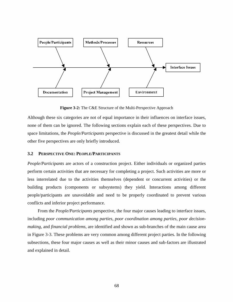
68
Figure 3-2: The C&E Structure of the Multi-Perspective Approach
Although these six categories are not of equal importance in their influences on interface issues,
none of them can be ignored. The following sections explain each of these perspectives. Due to
space limitations, the People/Participants perspective is discussed in the greatest detail while the
other five perspectives are only briefly introduced.
3.2 PERSPECTIVE ONE: PEOPLE/PARTICIPANTS
People/Participants are actors of a construction project. Either individuals or organized parties
perform certain activities that are necessary for completing a project. Such activities are more or
less interrelated due to the activities themselves (dependent or concurrent activities) or the
building products (components or subsystems) they yield. Interactions among different
people/participants are unavoidable and need to be properly coordinated to prevent various
conflicts and inferior project performance.
From the People/Participants perspective, the four major causes leading to interface issues,
including poor communication among parties, poor coordination among parties, poor decision-
making, and financial problems, are identified and shown as sub-branches of the main cause area
in Figure 3-3. These problems are very common among different project parties. In the following
subsections, these four major causes as well as their minor causes and sub-factors are illustrated
and explained in detail.
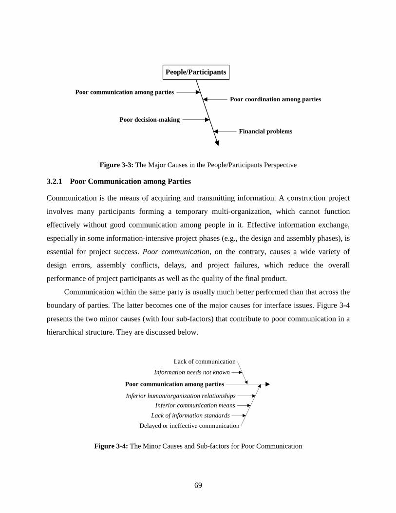
69
People/Participants
Poor coordination among parties
Poor decision-making
Poor communication among parties
Financial problems
Figure 3-3: The Major Causes in the People/Participants Perspective
3.2.1 Poor Communication among Parties
Communication is the means of acquiring and transmitting information. A construction project
involves many participants forming a temporary multi-organization, which cannot function
effectively without good communication among people in it. Effective information exchange,
especially in some information-intensive project phases (e.g., the design and assembly phases), is
essential for project success. Poor communication, on the contrary, causes a wide variety of
design errors, assembly conflicts, delays, and project failures, which reduce the overall
performance of project participants as well as the quality of the final product.
Communication within the same party is usually much better performed than that across the
boundary of parties. The latter becomes one of the major causes for interface issues. Figure 3-4
presents the two minor causes (with four sub-factors) that contribute to poor communication in a
hierarchical structure. They are discussed below.
Poor communication among parties
Delayed or ineffective communication
Information needs not known
Inferior human/organization relationships
Lack of information standardsInferior communication means
Lack of communication
Figure 3-4: The Minor Causes and Sub-factors for Poor Communication

70
3.2.1.1 Lack of Communication
The lack of communication easily leads to poor communication among parties. Unknown
information needs are the leading sub-factor. In general, there would be effective communication
when people (information providers or information users) realize that information is needed for
them to perform some function. Otherwise communication can hardly occur.
The industry knows well that subsequent activities usually need information from
preceding activities. The “pushing” method has been used for years to communicate such
information; i.e., people in preceding processes pass the information they think important to
people involved in succeeding processes. Sometimes this mode works very well, sometimes not.
The reason is two-fold. On one hand, the information dependency among parties is unclear when
a project or project organization is complex. On the other hand, people who provide the
information can hardly know the exact information needs of people who use the information.
The “pushing” communication does transmit some useful information, but also passes on some
redundant and misses some essential information. The resulting lack of communication has a
negative effect on information-dependent activities.
It is critical for the involved personnel to make their information needs transparent to
others at the earliest. Nevertheless, in industry practice, coordination among parties is
insufficient, which greatly limits the communication for such information needs. “Request for
Information (RFI),” becomes a widely used compensating method. Usually, a RFI is sent out
immediately before that information is going to be used for an activity and the user expects a
rapid response, which oftentimes cannot be accomplished. This incurs a potential error or delay
for that activity, which may deteriorate the inter-party relationship.
3.2.1.2 Delayed or Ineffective Communication
At times, communications do happen, but they are delayed or ineffective due to one of three
reasons:
First, inferior human/organization relationships prevent timely and effective
communication because it takes time for people to determine whom they should contact and then
to build a communication channel. Oftentimes, people involved in the inter-party communication
are not direct information providers or users; under such circumstances, initial or further

71
communications are required. This may result in delays or misunderstanding. In general, the
most effective communication is conducted through the best human/organization relationships
that are between people who directly generate or use the information.
Second, inferior communication means adversely affect communication. Fortunately,
besides traditional communication means including mail, telephone, facsimile, and face-to-face
meeting, new ways of communication such as electronic mail, instant message, voice/video
conference, and World Wide Web enrich users’ choices. Choosing the best means can make
communication most efficient and effective.
Third, the lack of information standards lowers the quality of information generated and
reduces the communication efficiency and subsequent information application. When
information is not created based on the same standard(s), such as the format, accuracy,
measurement unit, protocol, interface, etc., it can hardly be fully understood during
communications. At the implementation stage, information may be unqualified or has to be
converted. Very likely, errors are made, and some important information content is missing.
3.2.2 Poor Coordination among Parties
It is well known that a construction project has numerous participants who are more or less
interrelated. Little or intensive coordination amongst them is required. Coordination is very
critical in both design and construction to ensure compatibility between subsystems or
components and to minimize conflicts in schedules, site activities, and resource utilization
among different contractors. Coordination is also necessary between the design and construction
parties for enhancing constructability. Poor coordination among parties results in various
interface issues. Figure 3-5 illustrates the seven minor causes for poor coordination. They are
discussed below respectively.

72
Figure 3-5: The Minor Causes for Poor Coordination
3.2.2.1 Unaware of Interface Issues
Interface issues are very new to the industry. Project participants, especially the designers,
general contractor (GC), and specialty subcontractors are usually not familiar with these issues.
Although they witness or experience numerous interface-related problems such as design and
construction conflicts, delays, and low efficiency in assembly, they seldom categorize these
problems as “interface issues” and rarely realize that close coordination through organizational
boundaries could avoid and resolve most of these issues. As a result, interface-related
coordination is minimally performed among different project parties.
3.2.2.2 Unaware of Interface Ownership & Responsibilities
Each interface may involve different parties. The ownership and responsibilities for an interface
are neither clearly defined in project documents (e.g., contracts, specifications, drawings) nor
specified by people who administrate the design and construction processes (e.g., the architect,
GC’s superintendent). It remains unclear who is responsible for coordination and what should be
provided upon request during coordination. For example, in the shop drawings prepared by a
specialty subcontractor, related building elements or components that are out of his scope are
displayed and marked as “by others.” Without specifying who the others are, it is hard for the
specialty’s field people to coordinate their work with the others’. This oftentimes leads to poor

73
coordination on areas that are susceptible to interface issues. Pavitt and Gibb (2003) indicate that
eliminating the term “by others” can improve coordination and minimize interface issues.
3.2.2.3 Lack of Coordination between Design and Construction Parties
The constructability of physical interfaces in a project needs to be verified through coordination
between design and construction parties. In most project delivery methods, except Design-Build
(DB) and Engineer-Procure-Construct (EPC), the design and construction parties enter into a
project with separate and unrelated contracts that seldom explicate their coordination
responsibilities; the lack of coordination has been a very common problem in the industry for
years. The DB and EPC delivery methods make great progress by shifting the design-
construction coordination into the scope of a single contract. Their influence is limited since they
are still not the most widely applied delivery methods in the industry.
3.2.2.4 Lack of Resource and Personnel to Facilitate Coordination
IM has been a missing link of project management for a long time (Nooteboom 2004). In the
industry, contractors usually lack a specialized interface coordinator to supervise interface
coordination. Project management personnel are normally not experts in IM; their time is also
occupied by other management activities. In addition, with the increasing project complexity, the
total number of interfaces rises tremendously. Extra resources to facilitate IM are now not widely
available, and insufficient as well. For example, there are no well-known interface databases or
computer software for IM in the industry. As a result, IM performance is difficult to enhance.
3.2.2.5 Lack of Coordination among Specialties
Nowadays, many specialist contractors (also called specialty contractors) work on a jobsite as
subcontractors. Besides mechanical, electrical, foundation, and excavation contractors, major
materials or equipment suppliers who perform on-site installation are also regarded as specialty
contractors. They provide one or more of the following types of services: 1) design input, 2) bulk
materials supply, 3) components prefabrication/assembly, and 4) site erection services (Hsieh,
1998). Coordination among them is needed in very broad areas including design, work sequence,
material and information flows, space allocation, and resource utilization to avoid and resolve
various conflicts and ensure the quality and function of the built product.

74
In practice, there is no contracting relationship between specialties. Their respective
contracts do not fully specify coordination responsibilities. Under most circumstances,
specialties lack working experience and pre-established relationships with each other, which
could have reminded them of potential coordination needs. If the architect and GC’s
superintendent do not recognize these issues and help initiate coordination among them, the lack
of coordination among specialties occurs and causes critical interface issues.
3.2.2.6 Unable to Work on Site Simultaneously
Due to space limitations on a jobsite, work conducted by subcontractors usually follows a
sequential order; i.e., one subcontractor starts to work right after another one finishes his work.
This makes face-to-face, instant coordination between or among involved subcontractors
impossible when there are conflicts between building components or subsystems. When the
subsequent contractor faces conflicts, calling in the preceding one for coordination is also
difficult.
3.2.2.7 Unwilling to Bear Coordination and Resolution Responsibilities
Subcontractors are usually unwilling to bear coordination and resolution responsibilities for
potential or existing interface issues. One reason is that all subcontractors have their own
interests. They are willing to make every effort to avoid their own mistakes that lead to financial
penalty or loss of profit instead of considering the situation of others and conducting timely
coordination for them. Another reason is that a low profit margin limits subcontractors’
willingness and capability for coordination and resolution, which involves both time and cost.
3.2.3 Poor Decision-Making
Decision-making at various project stages influences a project delivery process and its final
product. Poor decision-making increases design errors, change orders, conflicts, rework, and
inter-party disputes in the design and construction phases, and easily causes time and cost
overruns. It also lowers the quality and systems performance of the built facility. Figure 3-6
shows the five minor causes that contribute to poor decision-making.

75
Figure 3-6: The Minor Causes for Poor Decision-Making
3.2.3.1 The Complexity and Uncertainties of a Project
Project complexity and uncertainties add great difficulty to the decision-making process. The
complexity of spaces, functions, components, or systems of a built facility as well as the selected
construction methods prevent decision-makers from reaching a good understanding of the project.
This oftentimes leads them to bad decisions in selecting design approaches, building
materials/components/systems, project delivery methods, subcontracting strategies, construction
methods, work sequences, or equipment/tools. The resulting interface issues cause various
project failures.
Uncertainties are usually unavoidable for any project. They normally relate to site geology,
weather, market, individual human performance, and emergencies. Uncertain conditions in a
project significantly increase the degree of difficulty in decision-making. Without taking them
into careful consideration, decision-makers may reach some decisions that are not adaptable in
an ever-changing environment. A wide variety of problems appear in interfaces between pre-
defined project elements and these uncertain conditions.
3.2.3.2 Bad Policy for Handling Inter-Company Relationships
Inter-company relationship is very important to a construction project. It ensures timely
communication and coordination as well as close cooperation among parties to streamline project
processes and maximize interest of the entire organization. The relationship can be fostered or
damaged with ease by decisions from any of participating parties. A company’s policies
implicitly affect its employees’ decision-making by influencing their attitude and flexibility. An
inappropriate policy, giving no emphasis to cooperation and reciprocity and passing risks on to

76
other parties, leads to poor decision-making, which easily disrupts the inter-company
relationship and effects serious interface issues.
3.2.3.3 Lack of Information or Outdated Information
In practice, decisions range from very simple to very complex. They can also be specific or
general. Simple, general decisions may be made just based on the common sense or best practice
the decision-makers have. To reach complex and/or more specific decisions, people need
accurate and sufficient information, especially when they do not have initial experience with a
“decision situation.” According to Sage (1992), decision-making is dependent upon many
contingency variables such as the objectives, needs, constraints, alterableness, and environment.
Accurate and sufficient information includes information verifying the real status of unsettled
project conditions as well as information helping clarify the above-mentioned variables. The lack
of information or outdated information probably delays the decision-making process or leads to
poor decisions based on assumptions.
3.2.3.4 Slowness of Owner’s Decision-Making
The owner’s decision-making directly or indirectly affects many aspects of a construction project.
Designers usually choose a very general design approach based on the owner’s initial
requirements. They also need the owner’s decisions for developing a design in detail. If such
decisions are late or absent, designers either postpone a design process or generate incomplete
design documents. When the owner’s decisions become available later, designers have to issue
change orders to supplement or alter original design documents.
Also, the owner’s decisions are needed by construction parties to make many of their own
decisions. When the owner’s decisions are delayed, affected construction parties have to put off
their decision-making process or make poor decisions. This could incur various problems such as
suspension of work, rework, and delay. Additionally, unexpected change orders from designers
interrupt construction parties’ planned activities and resource organization.
3.2.3.5 Lack of Experience in Design and Construction
An organization usually sets up some decision-making techniques and standard procedures for a
decision-maker to follow. However, making good or bad decisions still depends greatly on the
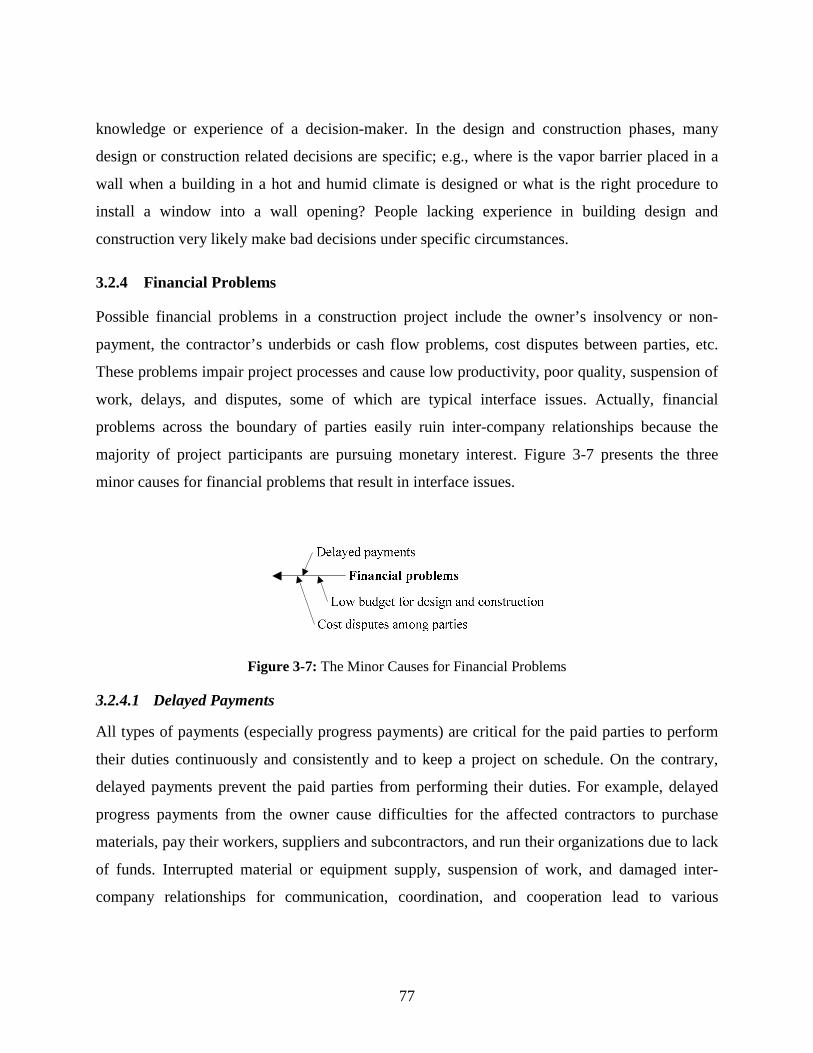
77
knowledge or experience of a decision-maker. In the design and construction phases, many
design or construction related decisions are specific; e.g., where is the vapor barrier placed in a
wall when a building in a hot and humid climate is designed or what is the right procedure to
install a window into a wall opening? People lacking experience in building design and
construction very likely make bad decisions under specific circumstances.
3.2.4 Financial Problems
Possible financial problems in a construction project include the owner’s insolvency or non-
payment, the contractor’s underbids or cash flow problems, cost disputes between parties, etc.
These problems impair project processes and cause low productivity, poor quality, suspension of
work, delays, and disputes, some of which are typical interface issues. Actually, financial
problems across the boundary of parties easily ruin inter-company relationships because the
majority of project participants are pursuing monetary interest. Figure 3-7 presents the three
minor causes for financial problems that result in interface issues.
Figure 3-7: The Minor Causes for Financial Problems
3.2.4.1 Delayed Payments
All types of payments (especially progress payments) are critical for the paid parties to perform
their duties continuously and consistently and to keep a project on schedule. On the contrary,
delayed payments prevent the paid parties from performing their duties. For example, delayed
progress payments from the owner cause difficulties for the affected contractors to purchase
materials, pay their workers, suppliers and subcontractors, and run their organizations due to lack
of funds. Interrupted material or equipment supply, suspension of work, and damaged inter-
company relationships for communication, coordination, and cooperation lead to various

78
interface issues. Delayed payments also damage mutual trust among parties; partnership is hard
to establish.
3.2.4.2 Low Budget for Design and Construction
The owner assumes that a low budget for design and construction could save him money. He
does not expect that this cost-cut may give rise to financial problems for both designers and
contractors. These problems produce far-reaching effects on many aspects of design and
construction. In the end, such a cost-cut comes at a high price to the project.
An insufficient budget in design, first, limits designers’ capability to find a better design
approach that is superior in many ways and helps achieve great savings for the owner in
construction. Second, a low budget reduces the details designers can provide in drawings or
specifications, which results in incomplete design. Third, a low budget makes designers
unwilling to bear more liabilities for design coordination. In fact, early design coordination under
the administration and supervision of designers is the most effective and efficient means to avoid
future assembly conflicts between building components or subsystems.
Similarly, a low budget for construction also produces many construction related problems.
Due to lack of funds, contractors hesitate to apply new technologies, which need initial
investments and continuous training. They may not implement required safety programs and
seldom provide adequate personal safety equipment for workers. They may hire unskilled labor,
which not only provides poor workmanship but also has no experience in handling complex
physical interfaces. Furthermore, contractors behave passively in communication, coordinate,
and cooperation with other parties.
3.2.4.3 Cost Disputes among Parties
Avoiding disputes and potential litigation in a construction project is a common goal for all
participating parties because a good relationship among them is an important factor leading to
project success. It helps avoid disputes and possible lawsuits that take time and money from all
the entangled parties. However, at times, disputes cannot be avoided since there are so many
competing interests amongst involved parties including the owner, designers, suppliers, and
contractors.

79
Cost disputes among parties may stem from poor estimates, underbids, change orders, cost
overruns, delayed or non-payments, defective works, bad weather, problems in procuring
materials and labor, on-site accidents, responsibilities for delays, or other causes. A dispute may
produce an array of serious damages to a project including loss of productivity, suspension of
work, extra work, delays, labor and materials escalation, loss of profit, economic loss, and
increased overhead for both the jobsite and home office. It is worth mentioning that such
damages may have a chain-breaking reaction from one affected party to other related parties,
such as his subcontractors and contractors performing subsequent or dependent tasks. Due to
space limitations, from the next section on, each perspective is only briefly discussed.
3.3 PERSPECTIVE TWO: METHODS/PROCESSES
Different design methods are employed to meet customer needs, manage the conformity of
technical solutions, and plan and govern the design process. The selected design methods affect
interfaces not only in design, but also in manufacturing, construction, operation and maintenance.
Construction methods and processes are determined mainly on design documents though a
certain degree of flexibility exists. The flexibility allows contractors to choose familiar and/or
economical construction methods and processes for their scopes of work.
In general, construction methods determine the interfaces that appear in construction. For
example, the stick-build housing construction method leads to a great number of simple types of
physical interface among raw building materials on the jobsite. Inappropriate methods and
processes may increase the uncontrollable interfaces on site and exacerbate the difficulty of IM.
The cause factors of interface issues from the Methods/Processes perspective are illustrated in
Figure 3-8. From this subsection on, each perspective is only briefly discussed; the selected
cause factors that are very critical to interface issues or hard to understand are explained in detail.
The interdisciplinary nature of a project adds coordination needs among designers or
specialty subcontractors to exchange interface parameter information. Besides the inadequacy of
information, poorly sequenced information exchange among designers or specialty
subcontractors complicates and delays the design process by producing information iteration
loops. In addition, a less thorough understanding of interfaces between components or
subsystems may result in design errors, low design constructability, and systems performance

80
failures of the built facility. The lack of considerations for modularity, standardization,
component integration, manufacturing, and construction in design increases the number and the
complexity of interfaces.
Figure 3-8: Interface Issue Cause Factors from the Methods/Processes Perspective
Manufacturers could face interface issues if they fail to choose proper manufacturing methods or
to plan and organize related production processes that involve materials, machines, and laborers.
Poor plant organization causes numerous conflicts in material or interim product movement
(O’Brien, Wakefield, and Beliveau 2002). Interface issues between workstations or processes
interrupt the smooth flow of production and compromise factory efficiency.

81
Complicated construction processes are one of the leading causes for construction and
assembly problems due to the added complexity for activity planning, organization, coordination,
and execution. The quality of interfaces would be largely impaired when the quality of
construction work stays low; for example, uneven or inadequate application of sealant adversely
affects the adhesive interface. Building elements or components constructed by different trades
may not fit each other in dimension due to lack of tolerance standards. Interface conflicts are
often caused by poorly designed work sequences and handling methods. Usually, concurrent or
overlapping activities may face more interface issues in process than sequential activities.
3.4 PERSPECTIVE THREE: RESOURCES
The construction project delivery process has to be supported by various resources. Labor,
materials, and equipment are traditional construction resources. This research also includes
information and space as resources. As discussed above, accurate and sufficient information is a
necessity for numerous activities in design and construction. Space availability is prerequisite for
construction activities. In practice, resource-related interface issues are very common. The cause
factors of interface issues from the Resources perspective are shown in Figure 3-9.
Labor issues are always concerns for contractors employing labor-intensive construction
processes. However, these issues are critical as well for contractors who use a great number of
pre-fabricated building products at the onsite assembly stage. Low-skilled labor more likely fails
physical connections or functional commitments between factory-made products. Those workers
also slow down the planned work progress and cause schedule conflicts and project delays.
Occasionally, even the skilled labor, when lacking cross-functional training, may still be unable
to handle complex physical or functional interfaces.
Workplace interface issues are caused by insufficient space or space conflicts among
workers performing concurrent activities, material storage and movements, and operating
equipment. Even when there are no visible conflicts, poor site organization and maintenance
increases potential hazards, which is an example of workplace interface issues. Adequate
preparation as well as proper workstation design and setup create the accessible interface
between workers and their operating space or building elements; otherwise, construction
activities have to be suspended until such an interface is ready.
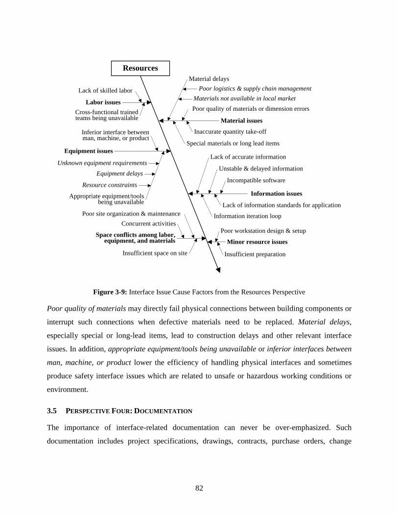
82
Resources
Minor resource issues
Labor issues
Lack of skilled labor
Material issues
Material delays
Poor quality of materials or dimension errors
Special materials or long lead items
Poor logistics & supply chain management
Equipment issues
Inferior interface between man, machine, or product
Appropriate equipment/tools being unavailable
Equipment delays
Resource constraintsInformation issues
Lack of accurate information
Information iteration loop
Inaccurate quantity take-off
Unknown equipment requirements
Materials not available in local market
Unstable & delayed information
Lack of information standards for application
Poor workstation design & setup
Insufficient preparationInsufficient space on site
Concurrent activitiesPoor site organization & maintenance
Incompatible software
Cross-functional trained teams being unavailable
Space conflicts among labor, equipment, and materials
Figure 3-9: Interface Issue Cause Factors from the Resources Perspective
Poor quality of materials may directly fail physical connections between building components or
interrupt such connections when defective materials need to be replaced. Material delays,
especially special or long-lead items, lead to construction delays and other relevant interface
issues. In addition, appropriate equipment/tools being unavailable or inferior interfaces between
man, machine, or product lower the efficiency of handling physical interfaces and sometimes
produce safety interface issues which are related to unsafe or hazardous working conditions or
environment.
3.5 PERSPECTIVE FOUR: DOCUMENTATION
The importance of interface-related documentation can never be over-emphasized. Such
documentation includes project specifications, drawings, contracts, purchase orders, change
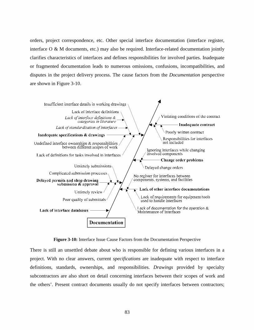
83
orders, project correspondence, etc. Other special interface documentation (interface register,
interface O & M documents, etc.) may also be required. Interface-related documentation jointly
clarifies characteristics of interfaces and defines responsibilities for involved parties. Inadequate
or fragmented documentation leads to numerous omissions, confusions, incompatibilities, and
disputes in the project delivery process. The cause factors from the Documentation perspective
are shown in Figure 3-10.
Figure 3-10: Interface Issue Cause Factors from the Documentation Perspective
There is still an unsettled debate about who is responsible for defining various interfaces in a
project. With no clear answers, current specifications are inadequate with respect to interface
definitions, standards, ownerships, and responsibilities. Drawings provided by specialty
subcontractors are also short on detail concerning interfaces between their scopes of work and
the others’. Present contract documents usually do not specify interfaces between contractors;

84
therefore, questions of responsibilities for contractors and disagreements about the scopes of
work arise frequently. In fact, even before bidding, preplanning of scopes and responsibilities for
the whole work and consideration of all contract interfaces should be given careful attention
(Shrive 1992). Kuprenas and Rosson (2000) suggest that additional contracts may be required to
pick up items omitted from trade contracts or missing items about interfaces.
The shop-drawing submission and approval process involves many participants. The
process itself needs to have complex inter-party relationships well handled and requires a timely
fashion to all transmission and review tasks. The quality of submittals should be guaranteed to
minimize resubmission. This time-consuming process, if not run smoothly, will delay a
contractor’s design process, and further influence the subsequent procurement and construction
process through interfaces among these processes.
Interface databases are rare in construction project information management. In the
literature, a few interface query systems were proposed, such as CladdISS for technical and
management aspects of cladding interfaces (Pavitt and Gibb 2003) and a point-n-click interface
for construction visualization (Danso-Amoako et al. 2003). These works are either specially
developed or still evolving. Therefore, when designers and contractors face unfamiliar interface
problems, there are actually no external resources available for help. The quality and efficiency
of interface design, handling, and management is low.
3.6 PERSPECTIVE FIVE: PROJECT MANAGEMENT
As indicated above, IM is indeed one aspect of project management. Poor IM lets many
interfaces run out of control and leads to numerous interface issues. On the other hand, there are
other aspects of project management, such as quality management, contract management, and
resource management. Poorly managed subcontracting, planning and scheduling, quality control,
resource allocation, etc. also lead to interface issues and increase the need for IM. The cause
factors of interface issues from the Project Management perspective are summarized in Fig. 3-11.
Workpackaging and subcontracting create a great number of external interfaces that
involve different contracting parties. Improperly separating work scopes and determining
subcontracts incur built-in weaknesses in detailed design and subsequent construction, such as
intensive information coordination, design information iteration loops, and complicated inter-
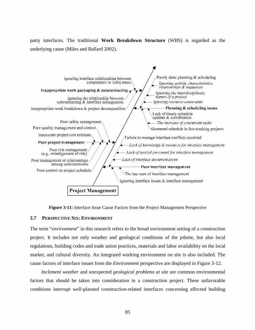
85
party interfaces. The traditional Work Breakdown Structure (WBS) is regarded as the
underlying cause (Miles and Ballard 2002).
Figure 3-11: Interface Issue Cause Factors from the Project Management Perspective
3.7 PERSPECTIVE SIX: ENVIRONMENT
The term “environment” in this research refers to the broad environment setting of a construction
project. It includes not only weather and geological conditions of the jobsite, but also local
regulations, building codes and trade union practices, materials and labor availability on the local
market, and cultural diversity. An integrated working environment on site is also included. The
cause factors of interface issues from the Environment perspective are displayed in Figure 3-12.
Inclement weather and unexpected geological problems at site are common environmental
factors that should be taken into consideration in a construction project. These unfavorable
conditions interrupt well-planned construction-related interfaces concerning affected building

86
components or processes. For example, heavy rain and the accumulated water could delay the
process of pouring foundation walls. Diverse local regulations, building codes and trade union
practices make it hard for contractors to practice nationwide. Culture was and is still not
considered an environmental factor in construction. But its significance has started to be noticed
by practitioners and researchers. Cultural diversity increases the difficulties in communication,
coordination and cooperation among construction people.
Figure 3-12: Interface Issue Cause Factors from the Environment Perspective
3.8 FINDINGS AND OUTCOMES
The multi-perspective approach has established some important findings and achievements:
First of all, this approach successfully performs an interface-related analysis of the current
built environment and presents a holistic view of what causes interface issues. The cause factors
identified under the six perspectives are very useful. They can be directly converted into success
factors for managing interfaces in construction projects or be further analyzed based on different
needs; e.g., the factor analysis and multiple regression performed by researchers at Hongkong

87
Polytechnic University to study Design-Build (Chan et al. 2001) and partnering (Chan et al. 2004)
in construction projects. On the other hand, the cause factors can also be summarized into a
series of interface management and control elements for future use.
Figure 3-13 shows one example of how the interface management and control elements can
be generated from the cause factors under the People/Participants category. The process uses a
method much like the content analysis methodology that can study the properties of textual
information. Through studying the cause factors, interface management and control elements are
summarized. The elements are either the key words of the cause factors (e.g., “information need”
is the key words of the cause factor unknown information needs), or the descriptive names
representing the project entities (e.g., “interface awareness” is the descriptive name of the cause
factor unaware of interface issues). All the defined elements are displayed in the affinity diagram
that can organize and present a large amount of data into logical categories.
In the process, if two or more elements can be identified from one cause factor, all of them
are listed to avoid missing any useful points. If the same element is generated later from another
factor, it is also recorded in the diagram. This means that one element could lead to interface
issues in different circumstances. Here, only two levels are shown under the main category as
any third level elements are merged into the second level. In Figure 3-14, six affinity diagrams
are used to display the interface management and control elements for the six main cause
categories respectively. These elements greatly facilitate the development of the Interface Object
Hierarchy in the proposed Interface Object Model (IOM) framework.
Secondly, the findings of the multi-perspective approach implicate that managing interfaces
is not a simple task, but that it requires a systems approach. Various project entities involved in
the cause factors or in the summarized elements are actually interrelated, such as construction
quality and skill of labor. They need to be properly managed and controlled within an IM system
to avoid, minimize, and resolve all kinds of potential interface issues. Those entities also spread
into the entire project delivery process (from design, construction, to O & M) and have gone far
beyond their original boundaries. Therefore, individual project management aspects including
IM should be integrated to maximize their performance so as to enable a dynamic and well-
coordinated construction system—the final goal of IM.

88
Figure 3-13: The Generation of Interface Management and Control Elements for the People/Participants Category

89
Figure 3-14: Potential Elements for Interface Management and Control
As shown in Figure 3-15, IM, though an individual project management aspect, also extends
over the scopes of other traditional project management aspects (cost, contract, communication,
resource, time, process, safety/risk, and quality). Through IM (the core of project management),
all the management aspects can be integrated as a coordinated system.

90
Figure 3-15: Systems Approach: Integrated Interface Management
In conclusion, the multi-perspective approach provides a theoretical base for seeking all-around
IM solutions. Specifically, it helps deeper understanding of interface issues and their causes.
Based on this understanding, the goal of IM can be determined and the specific interface
management and control elements can be identified. Future research can develop all-around IM
solutions.
91
CHAPTER 4: INTERFACE OBJECT MODEL FRAMEWORK
As discussed in Chapter 1, the large number of interfaces in a construction project and their
complexity easily make the most capable personnel fail in their responsibilities for interface
management (IM). IT implementation becomes the most effective way to record, track, check,
coordinate, and control complex interfaces within the computer integrated construction
environment. Modeling interfaces is regarded as the first step toward seeking appropriate IT
solutions for managing interface issues. The proposed Interface Object Model (IOM) identifies
applicable interface modeling objects, incorporates them into a well-structured, hierarchical data
structure, and defines data dependencies for implementation. It is the basis for modeling
numerous complex interfaces in construction projects and establishing interface databases that
can be widely used by the industry. This chapter presents a comprehensive IOM framework,
based on which further development of the IOM can be carried out in future research.
4.1 INTRODUCTION TO THE IOM
The IOM is proposed to be the basis for modeling numerous complex interfaces in construction
projects. The following subsections explain what the IOM is in three steps.
4.1.1 What is a Model?
The term model can be explained as a simple description or representation of a structure or
system. Presented in a general language, a model can be understood with ease and transformed
accurately between different systems or disciplines. There are many well-developed graphic
languages (e.g., the IDEF0, Express-G, and UML) available for modeling. In terms of the IFC,
the model means a formal specification of requirements that can be used by software authors to
create compliant software applications (IAI, 1999a). In this case, a model is used to
communicate requirements.
Modeling is considered a very good methodology to monitor reality, standardize or
simplify systems or a structure, explore and resolve potential problems, and finally instruct

92
relevant operations. Kartam et al. (1994) indicate that the development of valid, credible models
should be a logic precursor to automation.
4.1.2 What is an Object Model?
Different types of models can be created to fulfill specific purposes in designing, analyzing, and
implementing a system. The most commonly used models in the AEC/FM industry are process
models, information models, and object models.
A process model mainly describes the tasks or activities performed within a system or a
process. For example, the Integrated Building Process Model (IBM) developed by Chung (1989)
leads to a hierarchical breakdown of the building process. Sometimes, process models also show
how and what information needs to be communicated between tasks or activities. For instance,
the IDEF0 model published by the U.S. Air Force in 1981 successfully displays information
dependencies between processes.
Due to the importance of information flows in a process or system, information models are
created to mainly describe different types of information required by a system. For example, the
Building Project Model (BPM) developed by Luiten (1994) integrates product, activity, and
resource information for the purpose of computer-aided design for construction.
An object model can be explained as a representation of the structure of information and
the relationship between that information and other information. As aforementioned, the IFC
object model is defined as a representation of the information content and structure that needs to
be exchanged or shared for “things” occurring in the AEC/FM industry. It presents the classes as
well as their interfaces, attributes and relationships in a composite representation (IAI, 1999a).
An object model can therefore be understood as a special kind of information model.
4.1.3 What is the IOM?
The proposed IOM is an object model and therefore in many aspects similar to other object
models (e.g., the IFC). However, the IOM is a special outcome of this research for the purpose of
modeling the information content, structure and dynamic response of events related to interfaces.
Taking it one step further, the IOM is designed to represent the data structure of applicable
interface objects (the smallest, applicable interface modeling units) and the relationship between

93
such objects and building or project components. In implementation, any interface between
building or project components can be accurately modeled by using one or more such modeling
units.
4.1.3.1 An Object View of Interfaces
This research initiates the interface modeling method that models interfaces as objects. This
method is based on an object view of interfaces. The following comparison explains in detail this
view’s advantages in interface modeling.
Traditionally, interfaces are viewed and modeled as relationships or dependencies between
two entities (Figure 4-1) in many commonly used modeling languages in the construction field,
such as Express, Express-G, and the IDEFs. Such relationships or dependencies contain limited
information for a model to operate. Hence, operations and processes based on these models make
it difficult to achieve the expected performance.
Figure 4-1: The Conventional View of an Interface
The innovative object view considers interfaces controllable interface objects (Figure 4-2). These
objects are not only property collectors; they also contain operations sometimes also referred as
methods. Therefore, they can react to events in the object environment and trigger specific
interface handling processes as well. Based on this concept, interface management, control, and
handling becomes more effective and efficient.
Figure 4-2: The Innovative View of an Interface
4.1.3.2 Important Modeling Concepts in the IOM
Two concepts—class and object—are very important in the proposed IOM. They are the
commonly used terms in object models. This research adopts their definitions made in UML. A

94
class is defined as “the descriptor for a set of objects that share the same attributes, operations,
methods, relationships, and behavior.” The concept of class is either real world element (e.g.,
door and window) or can just contain algorithmic and computer implementation concepts.
Relatively, an object is an instance of a class, a concrete manifestation of an abstract description
(Rumbaugh et al, 1999).
Although what the IOM is modeling is often referred to as interface objects, they are
actually represented through classes of the real-world interface objects (instances) in a data
structure. Each interface object class in the IOM denotes a set of real-world interface objects that
have the same attributes, operations, methods, etc. The types of attributes and the brief
descriptions of operations, methods, etc. are listed within an interface object class in the IOM but
not ever specified there. During implementation, such an interface object class will be
instantiated and become a real-world instance. Then, all properties will be specified in the
greatest detail. The benefits of using classes in a data model are notable, such as the inheritance
that allows classes to inherit from higher level classes (superclasses), the easiness to extend the
model without re-inventing the superstructure, etc.
4.2 INTRODUCTION TO THE IOM FRAMEWORK
It is commonly thought that the model framework is very similar to or the same as the model
architecture. However, this research gives more meaning to the model framework. It is believed
that a model framework is needed before future research can accurately and fully develop a
proposed model. For that model, the framework usually performs some of the following
functions:
Setting the baseline,
Describing the entire structure,
Revealing model components and their relationship,
Showing modeling methods to be applied, or
Leaving spaces for future development and extensions.
Such a framework explains how individual model components are incorporated into a well-
structured system to perform the proposed function, and thus greatly enhances the
comprehension of future model developers.
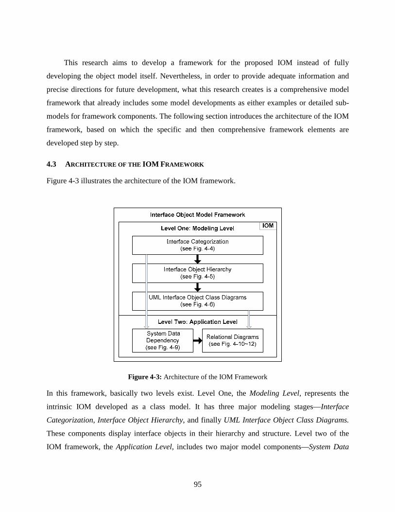
95
This research aims to develop a framework for the proposed IOM instead of fully
developing the object model itself. Nevertheless, in order to provide adequate information and
precise directions for future development, what this research creates is a comprehensive model
framework that already includes some model developments as either examples or detailed sub-
models for framework components. The following section introduces the architecture of the IOM
framework, based on which the specific and then comprehensive framework elements are
developed step by step.
4.3 ARCHITECTURE OF THE IOM FRAMEWORK
Figure 4-3 illustrates the architecture of the IOM framework.
Figure 4-3: Architecture of the IOM Framework
In this framework, basically two levels exist. Level One, the Modeling Level, represents the
intrinsic IOM developed as a class model. It has three major modeling stages—Interface
Categorization, Interface Object Hierarchy, and finally UML Interface Object Class Diagrams.
These components display interface objects in their hierarchy and structure. Level two of the
IOM framework, the Application Level, includes two major model components—System Data

96
Dependency and Relational Diagrams. These components identify both general and specified
data dependencies in the real world AEC/FM setting as an application of level one.
The most significant part of the framework is level one where interface objects are broken
down based on several categories and other classifications. Indeed, applicable interface objects
are the essence of the IOM. The modeling stages of level one are of different depth of abstraction.
The last stage (UML Interface Object Class Diagrams) includes a special descriptive language,
where all interface objects are properly specified and therefore ready for the Application Level.
Also, the Application Level is split into two stages. The first stage, System Data
Dependency, looks at applications on a higher level of abstraction and can in fact be used with
the first stage of the IOM. The second stage, Relational Diagrams, will be derived from the first
stage structure using the IOM defined in stage three of the Modeling Level. Within each level, a
solid arrow that connects two model components denotes a consecutive modeling step. The
hollow arrow, however, represents an application relationship between the two levels of the
framework; i.e., how model components of level two will find their hierarchical models in level
one.
4.4 FRAMEWORK DEVELOPMENT
According to the architecture presented above, the framework development consists of two parts:
1) developing a class model at the Modeling Level and 2) developing a relation model at the
Application Level. There are five model components in total. For the comprehensive IOM
framework, most of these model components are only partially developed but structured with
future extensions in mind. In the following, their development processes and examples are
presented respectively.
4.4.1 Interface Categorization
Class models can be considered the core of object-oriented development and design. A proper
approach to their development is essential. In this research, a general interface object
categorization is urgently needed in the development of the class model. Without a
categorization, the development of Interface Object Hierarchy lacks a fundamental data structure
because various interface objects should be defined according to specific categories and kept

97
under them for modeling and management. Therefore, such a categorization should be created in
the very beginning of the framework development. Fortunately, the interfaces and interface
objects can share a proper categorization.
In Chapter 2, this research has reviewed several types of interface categorizations made by
different researchers. These categorizations are all generic. Due to the different authorship, some
categories in different categorizations are actually identical according to their definitions such as
Physical Interface and Intrinsic Interface, or Contractual Interface and Project Interface; some
other categories, for instance, Functional Interface and Contractual Interface, overlap to some
extent. Actually, all these categorizations are neither complete nor sufficient for this research. On
the one hand, some categories like Discipline Interface or Functional Interface are not specified
by either examples or precise definitions, and hence are hard to understand and apply; on the
other hand, for many critical interfaces existing in the industry, it is hard to find any category to
fit them in. Therefore, the IOM framework should make its own specific and accurate interface
categorization, and then allow this categorization to be shared by the interface objects in the
development of the Interface Object Hierarchy.
This research chooses an approach that categorizes interfaces based on their characteristics.
Hence, the interface objects are also categorized according to their characteristics. The reasons
are two-fold. First, this approach is very helpful for object-oriented modeling to accurately
identify and categorize interface objects. Second, during implementation, people can easily
decide which interface object(s) should be used for modeling an interface; this is because when
people notice or experience an interface, its characteristics are most visible and some of them can
even be directly perceived. In this research, important characteristics distinguishing different
types of interfaces are physical, functional, performance, operation, and other activity
characteristics. Accordingly, the five main interface categories are identified as physical,
functional, contractual, organizational, and resource interfaces (shown in Figure 4-4). Their
definitions in broad construction settings are explained below. Simple categorization at a higher
level is beneficial to a hierarchical data structure. By using broad construction settings as the
background, the data model can be structured and developed more generically for wide
applications.

98
Figure 4-4: Interface Categorization
4.4.1.1 Category One: Physical Interface
This category comprises physical interactions between two or more facility elements or
components in any built facility (buildings, plants, bridges, roads, and other structures). Such
interactions include physical contacts, connections, as well as spatial relationships. Facility
elements—building elements in broad construction settings—usually refer to raw construction
materials; one piece of lumber or one sheet of wallpaper can be called a facility element. Using
primary elements is unavoidable when traditional construction methods are applied. For example,
2x4 lumber is the primary facility element for housing construction in the stick-build method.
Facility components—building components in broad construction settings—are manufacturing
products that are delivered to the job site as assemblies of raw construction materials. Those
components, such as roof/floor trusses, wall panels, or pre-cast bridge decks, are now widely
used in construction. Using factory-made components greatly reduces the number of physical
interfaces in a construction jobsite compared with using primary elements. However, the
interface complexity may increase because more primary elements might be involved in the
physical interface between two single components.
4.4.1.2 Category Two: Functional Interface
This category contains functional requirements/influences presented by one facility functional
element or system upon another functional element or system. A functional element is a facility
element or component either performing at least one function or having one influence on
something. For example, a window is a functional element performing several functions, such as

99
protecting the interior, providing daylight, and preventing heat loss or heat gain. A functional
system is much easier to understand, e.g., the HVAC (Heating, Ventilation, and Air Conditioning)
system performing heating, ventilating, or air conditioning for a building.
Functional requirement and functional influence are two interrelated aspects of a single
interaction. In other words, it is the influence that leads to the requirement being raised. Here is
one example. If element A receives some bad influence(s) from element B and therefore cannot
function properly, the requirement(s) of A will be given to B to reduce the negative influence(s).
Taking a building as the example, functional interactions within it consist of several functioning
aspects, including structural, humidity, thermal, acoustic, visual/lighting, and air quality/health.
4.4.1.3 Category Three: Contractual Interface
This category represents interactions among the general contractor (GC), subcontractors,
suppliers, and any external providers with regard to their scopes of work, schedules, and
responsibilities for construction. These parties usually have contractual relationships among each
other. Most of them (e.g., specialty subcontractors) are involved in certain workpackages that are
interrelated in building the facility. Therefore, contractual interfaces should comply with pre-
defined contractual obligations and simultaneously ensure that other types of interfaces (e.g.,
physical, functional) across different scopes of work can be performed successfully. Three major
characteristics that distinguish this category from others are defined below:
The described interactions are between parties that mainly are involved in the construction
stage, though the specialty subcontractors also perform some detailed design tasks.
Parties involved are bound by contracts and therefore have to perform their contractual
obligations or duties defined by such contracts.
Products or services those parties (except those GCs who only manage a project) provide are
(or belong to) individual workpackages and somewhat interrelated in the construction
system on the jobsite. Therefore they have to be carefully coordinated to avoid conflicts and
incompatibilities.
4.4.1.4 Category Four: Organizational Interface
This category includes interactions between various parties (including different divisions within
one party) in a construction project from its conception to final handover. The wide variety of

100
parties include the owner, designers, contractors and suppliers, operation & maintenance
contractors, labor associations, government agencies, and the public, community, or
neighborhood (if affected). Interfaces qualifying for the contractual interface category are
excluded.
Between most of these parties, for example, designers and government agencies,
contractors and the community, or designers and contractors (in traditional delivery
environments), there is no contracting relationship. Therefore, organizational interfaces among
parties are harder to organize and achieve due to lack of obligation. Also, the connections or
interactions between them are complex. They are of many different types, such as administration,
cooperation, supervision, inspection, regulation, and consultation. Within this category, the most
challenging interfaces are between the designers and associated contractors. Through these
interfaces, a large amount of design data needs to be accurately transformed into construction
operations.
4.4.1.5 Category Five: Resource Interface
This category involves interactions between equipment, labor, materials, space, or information
that are necessary for the design and construction of the facility and its components. Resource is
an evolving concept that has been gradually enriched with new contents since it appeared in
construction. Besides labor, equipment, and materials, the most recently added contents are space
and information. In this category, equipment includes not only traditional construction
tools/equipment but also communication, computing, and simulation tools/equipment (both
hardware and software). Information consists of project-related information, internal and external
databases, and knowledge/experiences widely available (e.g., on the “Web”). Accordingly,
resource interactions may include utility, space and information sharing, safety, learning,
operating, environmental influence, interoperability, etc.
According to the previous discussion, the interfaces and interface objects can share one
categorization when appropriate. Thus the above five interface categories become the basis for
determining interface object categories in the development of the Interface Object Hierarchy.
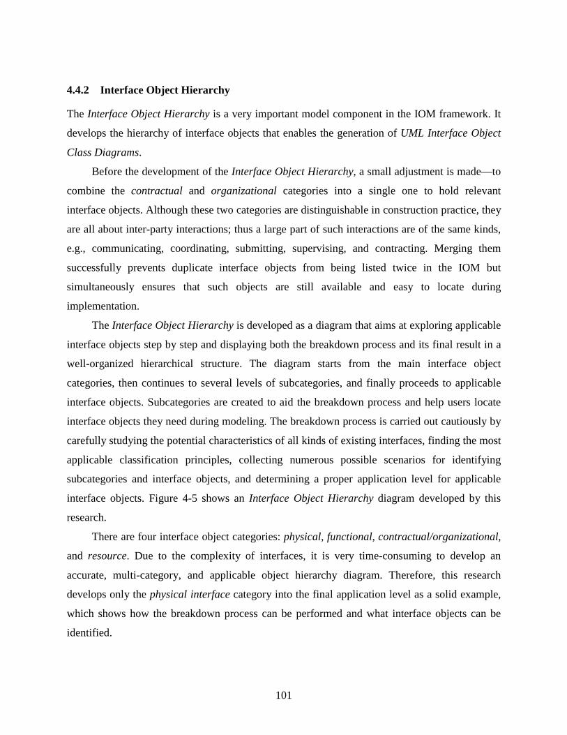
101
4.4.2 Interface Object Hierarchy
The Interface Object Hierarchy is a very important model component in the IOM framework. It
develops the hierarchy of interface objects that enables the generation of UML Interface Object
Class Diagrams.
Before the development of the Interface Object Hierarchy, a small adjustment is made—to
combine the contractual and organizational categories into a single one to hold relevant
interface objects. Although these two categories are distinguishable in construction practice, they
are all about inter-party interactions; thus a large part of such interactions are of the same kinds,
e.g., communicating, coordinating, submitting, supervising, and contracting. Merging them
successfully prevents duplicate interface objects from being listed twice in the IOM but
simultaneously ensures that such objects are still available and easy to locate during
implementation.
The Interface Object Hierarchy is developed as a diagram that aims at exploring applicable
interface objects step by step and displaying both the breakdown process and its final result in a
well-organized hierarchical structure. The diagram starts from the main interface object
categories, then continues to several levels of subcategories, and finally proceeds to applicable
interface objects. Subcategories are created to aid the breakdown process and help users locate
interface objects they need during modeling. The breakdown process is carried out cautiously by
carefully studying the potential characteristics of all kinds of existing interfaces, finding the most
applicable classification principles, collecting numerous possible scenarios for identifying
subcategories and interface objects, and determining a proper application level for applicable
interface objects. Figure 4-5 shows an Interface Object Hierarchy diagram developed by this
research.
There are four interface object categories: physical, functional, contractual/organizational,
and resource. Due to the complexity of interfaces, it is very time-consuming to develop an
accurate, multi-category, and applicable object hierarchy diagram. Therefore, this research
develops only the physical interface category into the final application level as a solid example,
which shows how the breakdown process can be performed and what interface objects can be
identified.
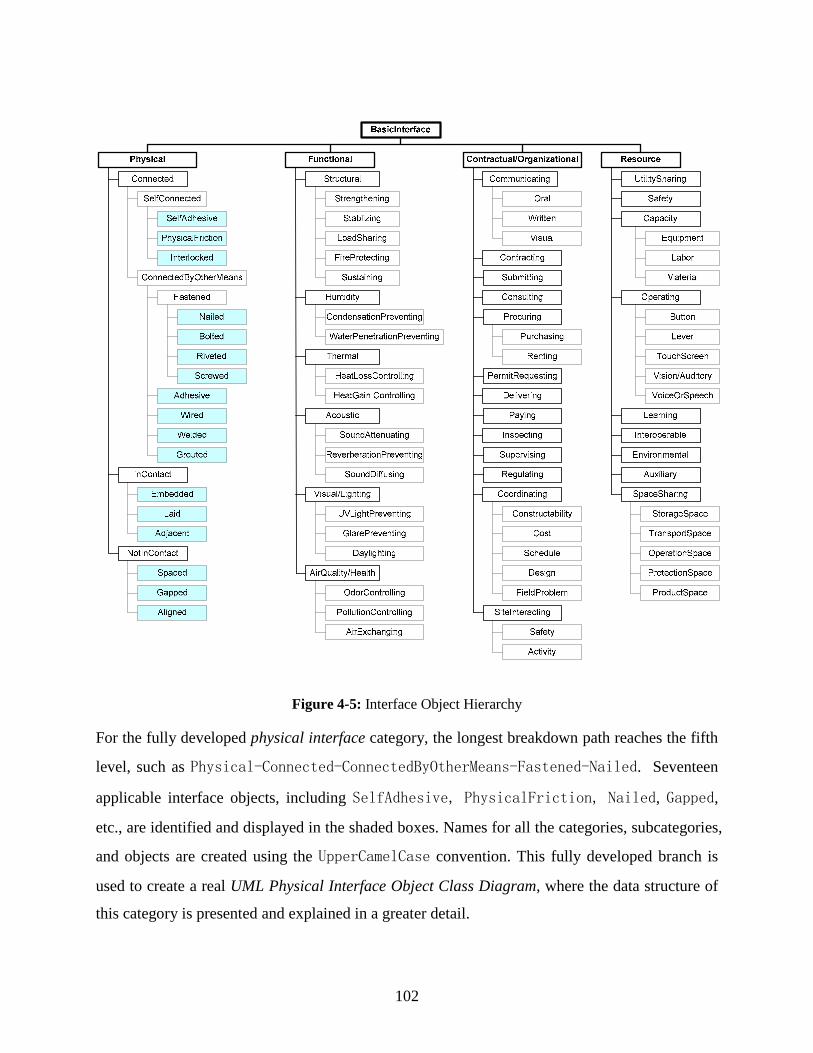
102
Figure 4-5: Interface Object Hierarchy
For the fully developed physical interface category, the longest breakdown path reaches the fifth
level, such as Physical-Connected-ConnectedByOtherMeans-Fastened-Nailed. Seventeen
applicable interface objects, including SelfAdhesive, PhysicalFriction, Nailed, Gapped,
etc., are identified and displayed in the shaded boxes. Names for all the categories, subcategories,
and objects are created using the UpperCamelCase convention. This fully developed branch is
used to create a real UML Physical Interface Object Class Diagram, where the data structure of
this category is presented and explained in a greater detail.

103
For the other three categories, this research develops them just into the third interim
levels—more indicatory subcategories which may not be 100 percent accurate and can be revised
in their future development. Even at an interim level, it can be seen that the data structure already
becomes very complex. To accurately determine subcategories and applicable interface objects is
extremely difficult. In the previous chapter, this research summarized a series of interface
management and control elements from the multi-perspective view of interface issues (the well-
developed C&E diagram). These elements, at the very detailed level, are greatly helpful for this
and future research to determine lower level interface object subcategories and applicable
interface objects in the IOM.
4.4.3 UML Interface Object Class Diagrams
The UML Interface Object Class Diagrams present detailed information for interface objects in a
standardized format. UML class diagrams are capable of including different types of detailed
information for the defined classes because several compartments, e.g., attributes, operations
with methods, or responsibilities, can be attached to a single class box according to the needs. On
the other hand, these diagrams are IT applicable since UML graphical representations stemming
from modeling language bundles can be automatically converted into code in a wide range of
commonly used software development tools such as C#, C++, and VB.
In the IOM, the Interface Object Hierarchy diagram can be fully transformed into a series
of UML class diagrams. Usually, each interface object category (including its sub-levels) will be
converted into a single UML diagram. Such a diagram may contain many classes and subclasses
with comprehensive information. If necessary, it will be easier to maintain child diagrams that
are more readable for users. These child diagrams can always be merged back into a single UML
diagram.
In the transformation process, the main category, subcategories, and objects in the Interface
Object Hierarchy Diagram become classes into which various detailed information is added.
Their hierarchical relationship is replaced by the generalization relationship in UML—a sort of
superclass-subclass relationship. This relationship allows a subclass to inherit attributes from its
superclass while still having additional, special attributes of its own. Thus, information is
gradually added into the diagram during transformation: The general information is added to the
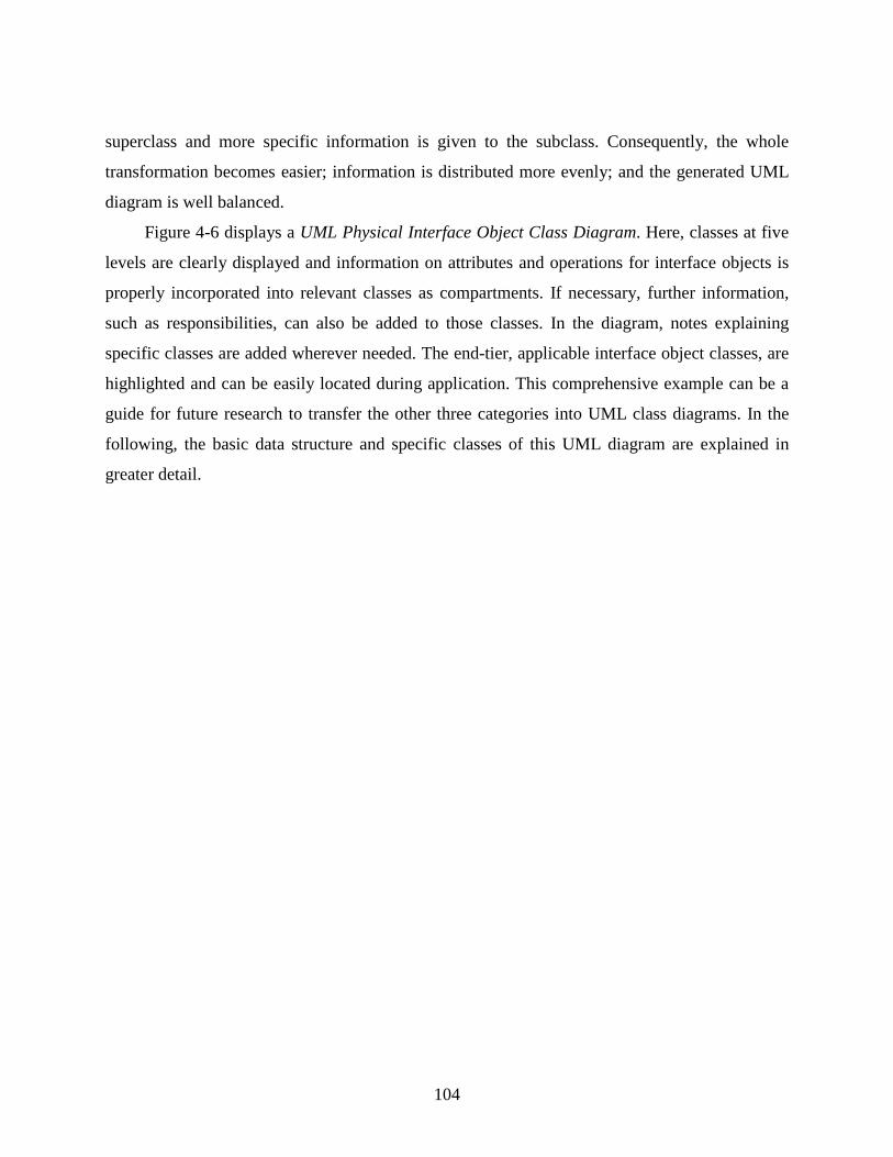
104
superclass and more specific information is given to the subclass. Consequently, the whole
transformation becomes easier; information is distributed more evenly; and the generated UML
diagram is well balanced.
Figure 4-6 displays a UML Physical Interface Object Class Diagram. Here, classes at five
levels are clearly displayed and information on attributes and operations for interface objects is
properly incorporated into relevant classes as compartments. If necessary, further information,
such as responsibilities, can also be added to those classes. In the diagram, notes explaining
specific classes are added wherever needed. The end-tier, applicable interface object classes, are
highlighted and can be easily located during application. This comprehensive example can be a
guide for future research to transfer the other three categories into UML class diagrams. In the
following, the basic data structure and specific classes of this UML diagram are explained in
greater detail.

105
Figure 4-6: UML Physical Interface Object Class Diagram

106
4.4.3.1 Data Structure
In the diagram, the highest superclass is called PhysicalInterface, which has three child
classes: 1) Connected, 2) InContact, and 3) NotInContact. Each has its definition and scope.
In UML, an italic class name represents an abstract class which cannot be directly instantiated;
then the concrete subclass(es) will be needed for instantiation. Here, PhysicalInterface is an
abstract class, as well as Connected, InContact and NotInContact classes.
Under the InContact and NotInContact subcategories, six end-tier applicable interface
object classes including Embedded, Laid, Adjacent, Aligned, Spaced, and Gapped are identified.
Under the Connected subcategory, two situations appear: SelfConnected and
ConnectedByOtherMeans. The former consists of three applicable interface object classes:
SelfAdhesive, PhysicalFriction, and Interlocked. The latter comprises four applicable
interface object classes (Adhesive, Wired, Grouted, and Welded) and one further category—
Fastened, which contains another four applicable interface object classes, namely Nailed,
Bolted, Riveted, and Screwed.
By the aid of such a step-by-step categorization, the data structure for physical interface is
well established and displayed. What types of properties/attributes need to be defined for each
applicable interface object class is also depicted along the breakdown path. To help future
developers and users better understand the UML class diagram, examples taken from some
transition classes and end-tier applicable interface object classes need to be given to explain how
these classes are defined and what the UML notations stand for.
Prior to presenting these examples, two concepts that are required for interface object
implementation need to be introduced first. They are simple interface and reference interface. In
general, a simple interface refers to the simplest type of interface interaction, which can be
represented by any interface object defined in the Interface Object Hierarchy diagram or UML
Interface Object Class Diagrams. A reference interface refers to a complex type of interface
interaction, which comprises several simplest interface objects (simple interfaces) and additional
components. In physical interface modeling, each type of physical interaction between two or

107
more facility elements or components can either be a simple interface or a reference interface
based on its physical characteristics. These two concepts are discussed further below.
4.4.3.2 Simple Interface and Reference Interface
In physical interface modeling, a simple interface refers to the simplest type of physical
interaction between two facility elements or components. Interface objects presented in the
physical interface object category and the corresponding UML physical interface object class
diagram are all simple physical interfaces, but at different levels. No matter whether the two
facility elements or components are connected, in contact, or not in contact with each other, this
type of interaction does not involve any additional component that needs to be specially designed
and manufactured for accomplishing the function required by the interaction. Common fasteners,
adhesives, and other simple mechanical or chemical means of connection are not considered
additional components. The simple interface is most elementary for modeling physical
interactions. It is also a required component for any reference interface.
A reference interface is more complex than a simple interface. In addition to simple
interfaces, it needs some additional component(s) for connecting two facility elements or
components. The additional components, such as masonry wall ties, are called interface
components. They exclude fasteners, adhesives, and other simple connecting materials. Usually,
interface components are added for connecting two facility elements or components through
surfaces that are not in contact with each other. This distinguishes a reference interface from the
connected by other means interface.
In physical interface modeling, a reference interface, when used, becomes a complex type
of interface object which holds several simple physical interface objects and additional interface
component(s). This is explained later within the Relational Diagrams.
4.4.3.3 Physical Interface Object Classes
In the following, several physical interface object class examples are presented and explained in
detail. The first example is the PhysicalInterface object class.
The PhysicalInterface is an abstract class that may not have direct instances. Its UML
notation is shown in Figure 4-7.
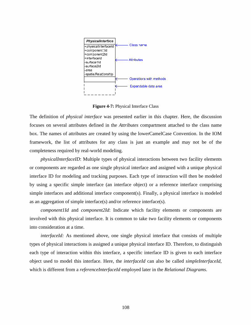
108
Figure 4-7: Physical Interface Class
The definition of physical interface was presented earlier in this chapter. Here, the discussion
focuses on several attributes defined in the Attributes compartment attached to the class name
box. The names of attributes are created by using the lowerCamelCase Convention. In the IOM
framework, the list of attributes for any class is just an example and may not be of the
completeness required by real-world modeling.
physicalInterfaceID: Multiple types of physical interactions between two facility elements
or components are regarded as one single physical interface and assigned with a unique physical
interface ID for modeling and tracking purposes. Each type of interaction will then be modeled
by using a specific simple interface (an interface object) or a reference interface comprising
simple interfaces and additional interface component(s). Finally, a physical interface is modeled
as an aggregation of simple interface(s) and/or reference interface(s).
component1Id and component2Id: Indicate which facility elements or components are
involved with this physical interface. It is common to take two facility elements or components
into consideration at a time.
interfaceId: As mentioned above, one single physical interface that consists of multiple
types of physical interactions is assigned a unique physical interface ID. Therefore, to distinguish
each type of interaction within this interface, a specific interface ID is given to each interface
object used to model this interface. Here, the interfaceId can also be called simpleInterfaceId,
which is different from a referenceInterfaceId employed later in the Relational Diagrams.

109
surface1Id and surface2Id: Indicating which surfaces of elements or components are
involved with a specific interface object.
Besides the attributes compartment, there are expandable data areas for the Operations with
Methods compartment, Responsibilities compartment, etc. Important object-oriented interface
information can always be added into the class according to the data needs.
The Connected interface object class represents a type of physical interaction in which two
facility elements or components are in contact with each other (touching or in immediate
proximity) and physically connected through the contacting surfaces by simple means including
mechanical, chemical, and/or other. There are two types of connected interface: One is self
connected and the other is connected by other means. Their names are self-explanatory. Here, the
SelfAdhesive interface object class (as shown in Figure 4-8) is explained in detail as an
applicable interface object class example.
Figure 4-8: Self_Adhesive Class
This is a concrete class which can have its instances. Examples are interfaces between self-
adhesive construction materials (e.g., wallpaper, tile, aluminum sheet, and spray foam insulation)
and their base materials (e.g., tile, drywall, polyethylene, and steel). There are eight important
attributes including working temperature, tightness, bond strength, pressure resistance, curing
time, stability, density, and durability. These attributes need to be accurately specified and
strictly followed during the interface handling process to ensure a quality self adhesive interface.
The operations may include apply, spray, or other activities.

110
The InContact interface object class refers to a type of situation where two facility
elements or components are in contact with each other but without a physical connection through
the contacting surfaces. For example, a pre-cast foundation wall rests on compacted gravel, or
two pieces of pavement tiles are placed adjacently. There are no permanent physical connections
existing to bond the two elements or components together.
The NotInContact interface object class represents a type of condition where two facility
elements or components are related to each other in space but not in contact. The two elements or
components may be aligned in space (Aligned); one may contain the other (Spaced); or a
constant gap may be kept between them (Gapped). For example, a corridor represents a gapped
interface between two parallel walls.
4.4.4 System Data Dependency
In IOM implementation, a critical issue exists; i.e., how interface objects identified in the IOM
can be used to model real-world interfaces in their construction contexts. A method to map
interface objects into construction settings of numerous interfaces should be found. In this
research, relational models at Level Two are created to perform such a mapping function.
Level Two, the Application Level, comprises two major model components: System Data
Dependency and Relational Diagrams. Both of them use UML static view class models, which
can describe the vocabulary of a system and specify structural relationships within it. The first
model component, System Data Dependency, shows the entire structure of the construction
project system and how the identified interface object categories fit into this structure. This UML
diagram is greatly simplified to display only the highest-level classes in the hierarchies of both
the system and the interface objects. It also serves as a parent diagram at Level Two to hold the
second-stage child relational diagrams.
It is apparent that the highest-level interface object classes are the main categories of
interface objects presented previously. For the construction project system to be modeled, one
question comes to the fore. What are the highest-level classes most necessary for this system?
In the literature, there are many project information models that have a hierarchical
structure. In those models, key project contents or entities are illustrated at a higher level. Froese
111
(1992) develops the General Construction Object Model (GenCOM) to improve the integration
of project management tools by using object-oriented models of construction projects. This
model defines the high-level object classes or entities as: activity, component, method, action,
resource, and project participant. The relationships among these object classes are also specified.
Luiten et al. (1993) define the conceptual Information Reference Model for AEC (IRMA). The
central concept is the project object, which consists of four major classes: product, contract,
activity, and resource (including agent). These high-level project object classes or entities are
referred to when a System Data Dependency is created in the IOM framework.
Figure 4-9 is a System Data Dependency diagram presented in UML. The high-level object
classes of the construction project system are defined as: built facility, facility component,
process activity, people/participant, and resource. The facility component object class plays an
important role in the model. It is located at the center of the model and connects other object
classes or entities with it. Process activities are performed by people/participants to construct or
handle facility components. Resources are used to conduct process activities. With the aid of
these relationships, the modeled information is integrated as a complete system and can be easily
incorporated into other building product models where project information is also organized
around facility components. In the diagram, the high-level interface objects—
PhysicalInterface, FunctionalInterface, Contractual/OrganizationalInterface, and
ResourceInterface—are properly incorporated into the model.
It is very important for the IOM framework to have the System Data Dependency diagram
well developed. This is because this diagram can be used to derive specific project or facility
components that are essential, constituent elements of the Relational Diagrams introduced below.
In addition, this diagram shows which category or categories of interface objects are related to
these components. The System Data Dependency acts as the parent diagram for relational
diagrams that present lower level details.

112
Figure 4-9: System Data Dependency

113
4.4.5 Relational Diagrams
The Relational Diagrams comprise another group of UML diagrams. Most of them describe data
dependencies between specific facility or project components and their appropriate interface
objects in selected construction contexts. These contexts can be diverse project conditions that
are compatible with selected project delivery methods or construction methods. The facility or
project components at a detailed level are derived from the major project objects or entities
displayed in the System Data Dependency. Based on the needs of interface modeling, proper
interface objects are selected to fit into specific construction contexts.
Figure 4-10 illustrates the data dependency (contextual relationship) between the physical
interface objects and facility components. This is one of the simplest types of data dependency in
the IOM. In the diagram, the association classifier connecting two classes is capable of
specifying data dependencies and consequently increases the model applicability. The
highlighted object classes belong to the scope of interface modeling (proposed by this research)
while the other classes should be modeled in building product models currently existing in the
industry. As shown here, any physical interface can be modeled as an aggregation of simple
interface(s) and/or reference interface(s), and any reference interface is composed of simple
interfaces and additional interface component(s). Each reference interface is specified by an
attribute—reference interface ID.
Compared with the data dependency between the physical interface objects and facility
components, data dependencies between other types of interface objects and related project
components are more complex to model. The identified cause factors (in Chapter 3) can be used
to create numerous detailed project scenarios where both project components and the involved
interfaces are illustrated to a certain degree. Relational models can be created to incorporate
relevant interface objects into such project scenarios and precisely depict the relationships or
dependencies between them. Based on these relational models, interface modeling can be
performed and further used to help the management and control of various interface issues
described in those project scenarios.
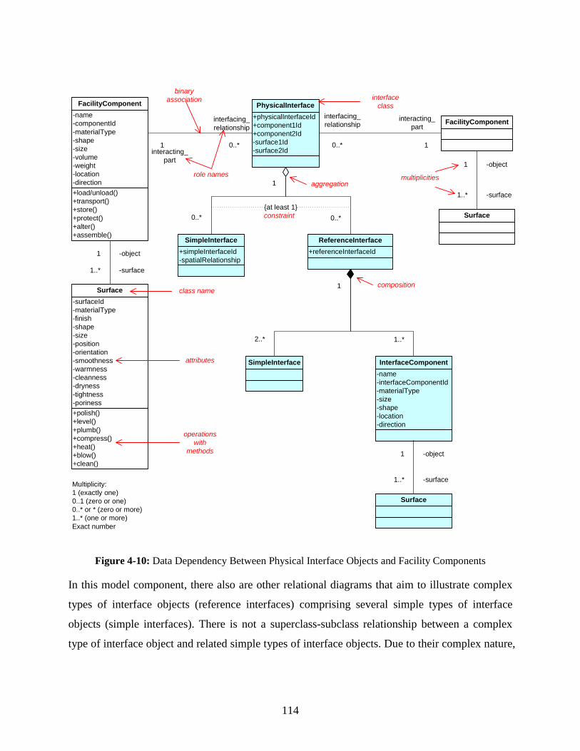
114
+load/unload()+transport()+store()+protect()+alter()+assemble()
-name-componentId-materialType-shape-size-volume-weight-location-direction
FacilityComponent
+polish()+level()+plumb()+compress()+heat()+blow()+clean()
-surfaceId-materialType-finish-shape-size-position-orientation-smoothness-warmness-cleanness-dryness-tightness-poriness
Surface
-object1
-surface1..*
+physicalInterfaceId+component1Id+component2Id-surface1Id-surface2Id
PhysicalInterface
FacilityComponent
1 0..*interacting_
part
interfacing_relationship
0..* 1
interacting_part
interfacing_relationship
Surface
-object1
-surface1..*1
0..*
+simpleInterfaceId-spatialRelationship
SimpleInterface+referenceInterfaceId
ReferenceInterface
0..*{at least 1}
SimpleInterface-name-interfaceComponentId-materialType-size-shape-location-direction
InterfaceComponent
1
2..* 1..*
Surface
-object1
-surface1..*
aggregation
interface class
class name
attributes
operations with
methods
constraint
role names multiplicities
binary association
Multiplicity:1 (exactly one)0..1 (zero or one)0..* or * (zero or more)1..* (one or more)Exact number
composition
Figure 4-10: Data Dependency Between Physical Interface Objects and Facility Components
In this model component, there also are other relational diagrams that aim to illustrate complex
types of interface objects (reference interfaces) comprising several simple types of interface
objects (simple interfaces). There is not a superclass-subclass relationship between a complex
type of interface object and related simple types of interface objects. Due to their complex nature,

115
class models at Level One cannot capture them. Such complex types of interface objects exist
widely in interface modeling. They represent real-world interface relationships that repeatedly
appear in construction projects. These complex types of interface objects need to be defined prior
to interface modeling. If generalized as object modeling patterns, they can greatly increase the
speed of modeling common real-world interfaces.
Here, two relational diagrams are presented to illustrate the reference interface type for
physical interface modeling. Figure 4-11 shows a simple type of reference interface, which
consists of two simple interfaces and one interface component—the additional component used
to connect the two facility elements or components. A real-world example given here is the
physical interface between a door panel and a door frame. When the door is hinged to the frame,
the first and second basic interfaces in the diagram can all be modeled by the Screwed interface
object and the interface component is the hinge.
Figure 4-11: The Simple Type of Reference Interface
Figure 4-12 shows a compound type of reference interface, which comprises a chain of simple
interfaces and interface components. A real-world example will be given in the next chapter
during the model validation.

116
Figure 4-12: The Compound Type of Reference Interface
During implementation, users can freely choose some of these relational diagrams whose
contexts are compatible with project conditions that they are going to model. Furthermore, users
can also create their own relational diagrams based on any unique project conditions that they are
facing.
Up to now, the development processes, sub-models, and examples for all the model
components have been presented. Figure 4-13 shows a graphic view of the IOM framework as a
whole. Here, each model component is illustrated by the corresponding diagram(s) developed by
this research. The comprehensive framework provides not only guidelines for continued
development but also precise examples showing what the developed model components may
look like. Those detailed examples are very helpful for the model validation conducted in
Chapter 5.

117
Figure 4-13: The Comprehensive IOM Framework

118
CHAPTER 5: INTERFACE OBJECT MODEL VALIDATION
In this research, physical interface modeling is chosen for validating the proposed IOM
(Interface Object Model). This chapter first presents a decision-making model, which helps the
user decide which physical interface object(s) should be used for modeling specific physical
interfaces, and demonstrates how the decision-making process and detailed physical interface
modeling can be performed. Then this chapter introduces the U.S. housing construction process
and related interfaces. The focus is located on two complete construction processes. Based on the
physical conditions occurring in these two processes, physical interface modeling is performed
and presented to validate: 1) how the proposed interface modeling method works in complete
construction processes under real-world conditions and 2) how effective the fully developed
applicable physical interface objects are for the modeling.
5.1 THE DECISION-MAKING MODEL
The IOM validation implements two procedures:
A decision-making model is first built and used to determine the appropriate physical
interface object subcategories as well as applicable interface objects for modeling physical
conditions.
Physical interface modeling is performed in two complete construction processes. The
modeling validates that various types of real-world physical interfaces can be modeled by
using interface object classes identified in the IOM framework.
In this section, a decision-making model is presented. Then, a decision-making process is
demonstrated by running one decision-making scenario. Finally, two modeling examples are
given to illustrate how specific interface information can be added to instantiate the selected
interface object classes.
5.1.1 The Decision-Making Model for Physical Interface Modeling
As shown in Figure 5-1, the decision-making model is actually a flow chart which displays a
standardized decision-making process. The process involves six if-then scenarios and five
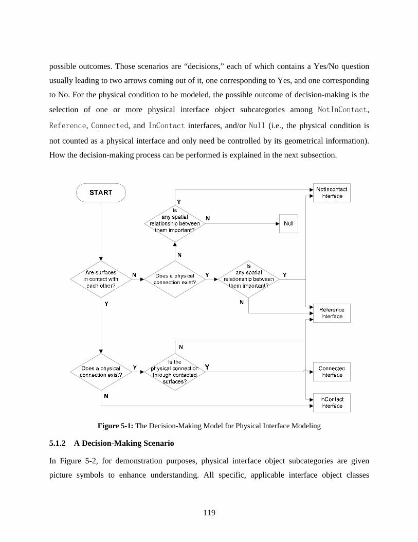
119
possible outcomes. Those scenarios are “decisions,” each of which contains a Yes/No question
usually leading to two arrows coming out of it, one corresponding to Yes, and one corresponding
to No. For the physical condition to be modeled, the possible outcome of decision-making is the
selection of one or more physical interface object subcategories among NotInContact,
Reference, Connected, and InContact interfaces, and/or Null (i.e., the physical condition is
not counted as a physical interface and only need be controlled by its geometrical information).
How the decision-making process can be performed is explained in the next subsection.
Figure 5-1: The Decision-Making Model for Physical Interface Modeling
5.1.2 A Decision-Making Scenario
In Figure 5-2, for demonstration purposes, physical interface object subcategories are given
picture symbols to enhance understanding. All specific, applicable interface object classes
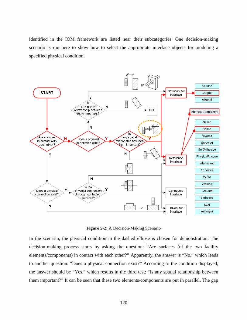
120
identified in the IOM framework are listed near their subcategories. One decision-making
scenario is run here to show how to select the appropriate interface objects for modeling a
specified physical condition.
Figure 5-2: A Decision-Making Scenario
In the scenario, the physical condition in the dashed ellipse is chosen for demonstration. The
decision-making process starts by asking the question: “Are surfaces (of the two facility
elements/components) in contact with each other?” Apparently, the answer is “No,” which leads
to another question: “Does a physical connection exist?” According to the condition displayed,
the answer should be “Yes,” which results in the third test: “Is any spatial relationship between
them important?” It can be seen that these two elements/components are put in parallel. The gap

121
between them is very important and needs to be controlled, so the decision is “Yes,” which
finally points to the NotInContact and Reference interface subcategories.
Under the NotInContact category, there are three identified physical interface objects.
According to the selected condition, the interface object, Gapped, is chosen for modeling. When
the Reference interface subcategory is involved, it means that additional interface components,
in this case, two steel angles, are required. As displayed in Chapter 4, a reference interface
should be modeled as a chain of simple interfaces and interface component(s). Here, Bolted is
chosen to model the two simple interfaces among the facility elements/components and the steel
angles. Figure 5-3 shows the modeling structure for this physical condition. Comprehensive
interface information is not available at this stage.
Figure 5-3: The Physical Interface Modeling Structure for the Selected Physical Condition
5.1.3 Interface Modeling Examples
In this subsection, two real-world physical interface examples chosen from a building façade
project are presented for modeling. Detailed information displayed in the CAD drawings is
added into the interface models for instantiation.
The CAD drawing of the first example (Figure 5-4) shows a bottom sectional detail
illustrating how a piece of glass panel fits into a U-channel. There are two main facility elements
or components. One is a 12mm thick clear glass panel; the other is a 3mm thick 40x34x40mm

122
stainless steel U-channel. The other building materials involved include sealant, backer rod, and
wood spacer. There are several wood spacers (300mm center to center) for each piece of glass
panel. Backer rod is caulked in the two gaps between the glass panel and U-channel continuously.
Sealant is applied on top. These materials are for filling purposes only, through which no
permanent physical connection can be established. By following the decision-making process
demonstrated above, the NotInContact interface object subcategory is first selected for
modeling, then the Gapped interface object. In this research, the difference between the Gapped
and Spaced interface objects is clearly defined:
Gapped: The surface of a facility element or component is not in contact with the surface of
another facility element or component, and a constant gap exists between these two surfaces.
This gap needs to be specified in the design and also strictly executed and controlled during
construction.
Spaced: One facility element or component is providing a space to contain another facility
element or component. No contact is required under most circumstances.
Figure 5-4: Glass Panel Bottom Sectional Detail
Accordingly, the interface modeling is performed and displayed in Figure 5-5. Properties of the
glass panel and U-channel are neither listed nor specified here. This information should have
been modeled in the concerning object-oriented building product model, where, however,
operations with methods on these facility elements or components are usually not modeled. For
the two interface objects, all properties including component ID, surface ID, area, spatial
relationship, width of gap, filling material type, etc. are specified. Operations are also briefly

123
described. This supplements the project information provided by the traditional building product
model and helps automatic interface coordination and control. In this example, the two interface
objects have the same type—Gapped. But their simple interface IDs, GP001 and GP002, are
different, which helps distinguish one from the other.
Figure 5-5: Interface Object Modeling Example I
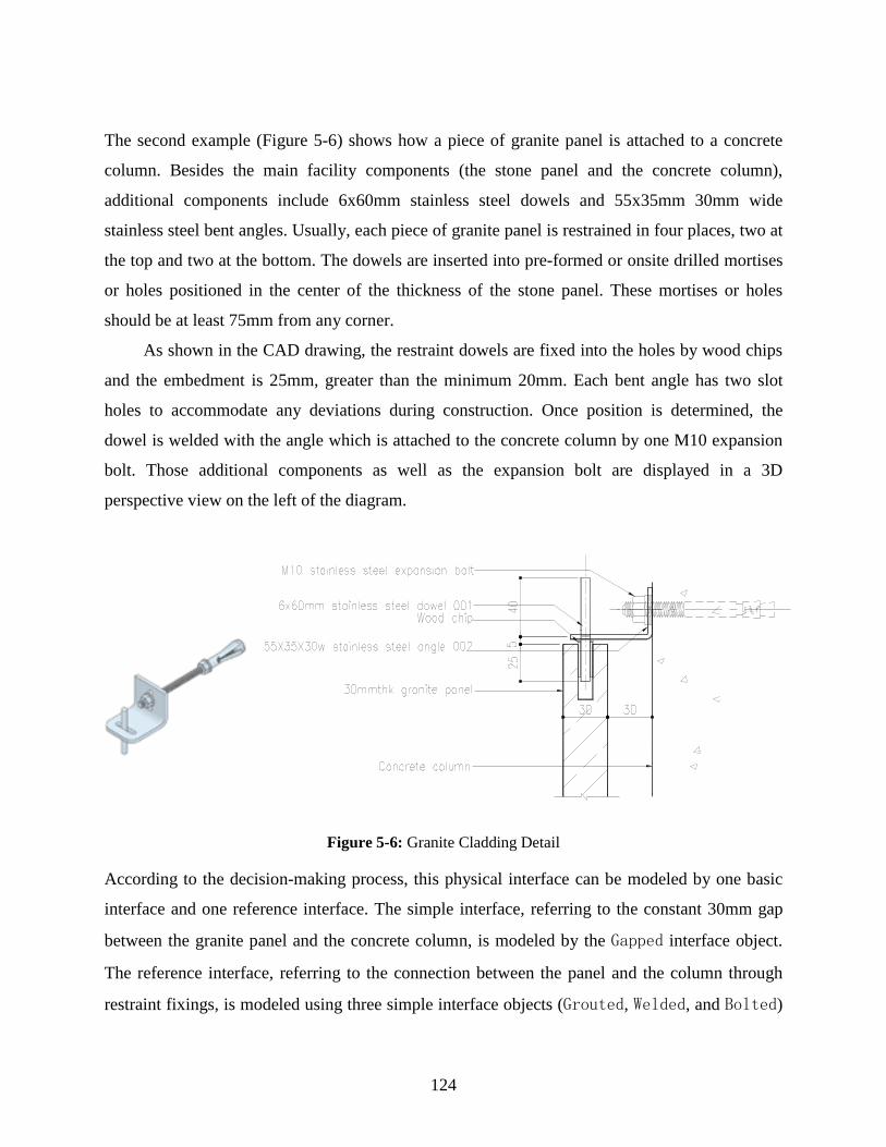
124
The second example (Figure 5-6) shows how a piece of granite panel is attached to a concrete
column. Besides the main facility components (the stone panel and the concrete column),
additional components include 6x60mm stainless steel dowels and 55x35mm 30mm wide
stainless steel bent angles. Usually, each piece of granite panel is restrained in four places, two at
the top and two at the bottom. The dowels are inserted into pre-formed or onsite drilled mortises
or holes positioned in the center of the thickness of the stone panel. These mortises or holes
should be at least 75mm from any corner.
As shown in the CAD drawing, the restraint dowels are fixed into the holes by wood chips
and the embedment is 25mm, greater than the minimum 20mm. Each bent angle has two slot
holes to accommodate any deviations during construction. Once position is determined, the
dowel is welded with the angle which is attached to the concrete column by one M10 expansion
bolt. Those additional components as well as the expansion bolt are displayed in a 3D
perspective view on the left of the diagram.
Figure 5-6: Granite Cladding Detail
According to the decision-making process, this physical interface can be modeled by one basic
interface and one reference interface. The simple interface, referring to the constant 30mm gap
between the granite panel and the concrete column, is modeled by the Gapped interface object.
The reference interface, referring to the connection between the panel and the column through
restraint fixings, is modeled using three simple interface objects (Grouted, Welded, and Bolted)

125
and two additional interface components (the stainless steel dowel and the stainless steel angle).
The expansion bolt is one type of standard fastener and belongs to the Bolted interface object;
therefore it is not considered an individual interface component. The pertinent interface
modeling is displayed in Figure 5-7.
These two examples successfully illustrated:
1) How the appropriate interface object subcategories and applicable interface objects for the
selected physical condition can be determined through the proposed decision-making process.
2) How the graphic-based, detailed physical interface information can be modeled using the
object-oriented modeling method.
Besides these individual examples, in the following, the IOM validation is performed in broad
construction contexts—relatively complete construction processes. If the physical interface
modeling is proven workable, it can be assumed that the other four types of interfaces can also be
accurately modeled after relevant applicable interface objects are defined. Due to the complexity
of the IOM validation in complete construction processes, the modeling only stays at a level
where the applicable interface objects are identified but not instantiated by recording detailed
project information.

126
Figure 5-7: Interface Object Modeling Example II
127
5.2 IOM VALIDATION IN SELECTED HOUSING CONSTRUCTION PROCESSES
Although this research aims to deal with overall interface issues in general construction contexts,
it chooses housing construction as its specific background for extended discussions, real-world
examples, as well as model validations. The reasons are:
Housing construction represents a large and very important portion of the U.S. construction
industry.
The homebuilding process is comparatively simpler than commercial construction.
Interfaces are easier to identify and monitor. Homebuilding can be a paradigm for other
complex types of construction.
Due to the mass production of similar single-family houses and townhouses, IM strategies to
be developed can be used repeatedly and widely. Timely and broad feedback can be
obtained for future development.
5.2.1 The U.S. Housing Construction Process
As aforementioned, in the U.S. housing construction industry, stick-build is still the prevailing
form of “industrialized” housing. This is a traditional craft-based homebuilding process, which is
labor intensive, long lead-time, and subcontractor-based. Figure 5-8 models the operation of the
stick-build homebuilding process in a UML use case diagram.
In this example, 27 sub-processes, from Excavate Footer to Occupation, were identified.
They were performed in a sequence. There were 21 subcontractors in total hired to build a house.
They entered the process at different points in time and conducted one or more sub-processes.
For example, the excavation subcontractor excavated the footer first, and came back later for
backfill. Sometimes, two subcontractors such as the framing subcontractor and lumber supplier
performed the same sub-process. To keep a smooth production and avoid potential conflicts
among them, close communication and coordination is essential.
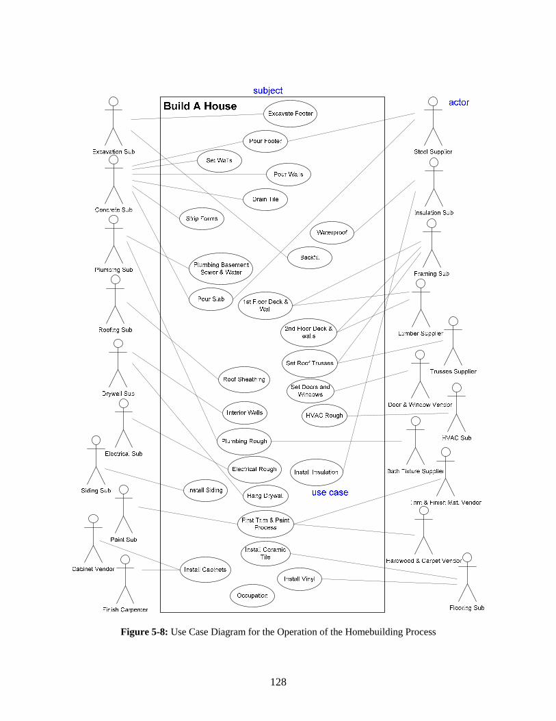
128
Figure 5-8: Use Case Diagram for the Operation of the Homebuilding Process
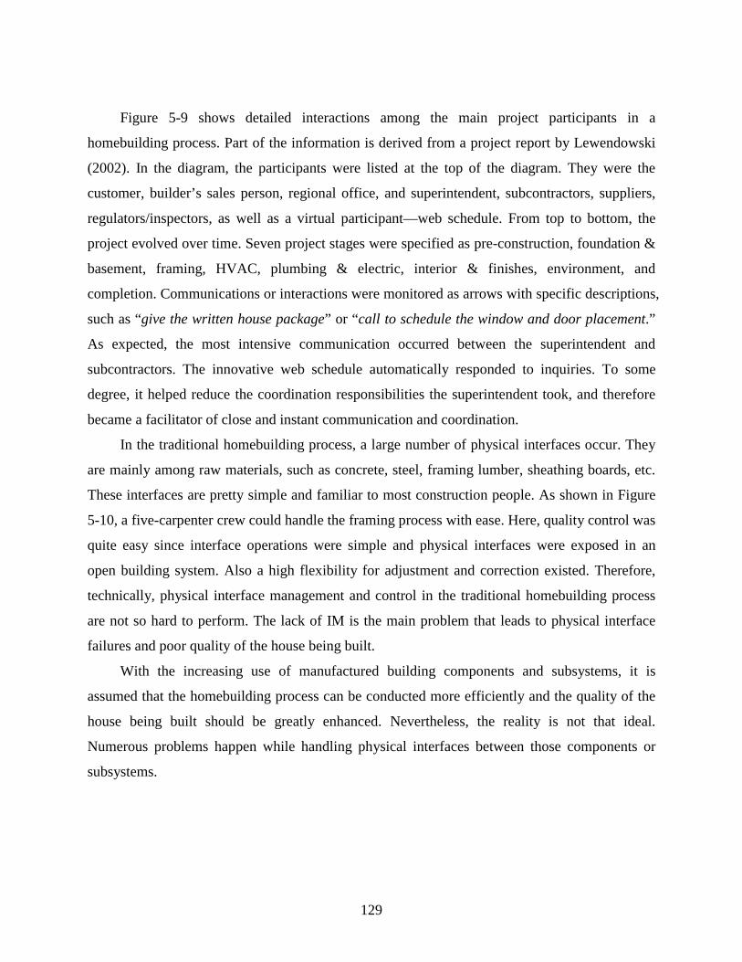
129
Figure 5-9 shows detailed interactions among the main project participants in a
homebuilding process. Part of the information is derived from a project report by Lewendowski
(2002). In the diagram, the participants were listed at the top of the diagram. They were the
customer, builder’s sales person, regional office, and superintendent, subcontractors, suppliers,
regulators/inspectors, as well as a virtual participant—web schedule. From top to bottom, the
project evolved over time. Seven project stages were specified as pre-construction, foundation &
basement, framing, HVAC, plumbing & electric, interior & finishes, environment, and
completion. Communications or interactions were monitored as arrows with specific descriptions,
such as “give the written house package” or “call to schedule the window and door placement.”
As expected, the most intensive communication occurred between the superintendent and
subcontractors. The innovative web schedule automatically responded to inquiries. To some
degree, it helped reduce the coordination responsibilities the superintendent took, and therefore
became a facilitator of close and instant communication and coordination.
In the traditional homebuilding process, a large number of physical interfaces occur. They
are mainly among raw materials, such as concrete, steel, framing lumber, sheathing boards, etc.
These interfaces are pretty simple and familiar to most construction people. As shown in Figure
5-10, a five-carpenter crew could handle the framing process with ease. Here, quality control was
quite easy since interface operations were simple and physical interfaces were exposed in an
open building system. Also a high flexibility for adjustment and correction existed. Therefore,
technically, physical interface management and control in the traditional homebuilding process
are not so hard to perform. The lack of IM is the main problem that leads to physical interface
failures and poor quality of the house being built.
With the increasing use of manufactured building components and subsystems, it is
assumed that the homebuilding process can be conducted more efficiently and the quality of the
house being built should be greatly enhanced. Nevertheless, the reality is not that ideal.
Numerous problems happen while handling physical interfaces between those components or
subsystems.

130
Figure 5-9: Sequence Diagram for Interactions Between Participants in a Homebuilding Process

131
Figure 5-10: “Stick-Build” Framing Process
Actually, factory-made components and subsystems increase the complexity of physical
interfaces during installation. Both the superintendents and workers are not familiar with how to
control those interfaces. In addition, the flexibility for adjustment is reduced compared with that
in the stick-build process. As a result, numerous physical conflicts occur and the installation
process is often times interrupted and delayed. Figure 5-11 displays some typical physical
interface failures in the homebuilding process. These failures involve factory-made components,
such as integrated wall panels, floor decks, roof trusses, and interior metal-framed walls.
This research performs physical interface object modeling mainly in two selected housing
construction processes which involve a large number of factory-made building components. Here,
the main purpose of IOM validation is to demonstrate that the identified physical interface
objects are capable of modeling physical interfaces in complete construction processes. To keep
the model simple, detailed information specifying each physical interface is not provided.

132
Figure 5-11 : Typical Physical Interface Failures
In the following subsections, the two selected housing construction processes, foundation wall
installation and componentized superstructure framing, are briefly introduced. Interfaces within
them, especially physical interfaces, are discussed respectively. Choosing the housing
construction processes for validation does not limit the IOM’s capability to model interfaces in
any other type of construction. On the contrary, it facilitates better understanding and accurate
application.
5.2.2 Foundation Wall Installation
To help the holistic understanding of foundation wall installation and componentized
superstructure framing processes, this research conducted case studies in construction projects of
a large national homebuilder. Figure 5-12 provides an overall structure of housing foundation
and superstructure subsystems based on the author’s observation and understanding.
Failed joint
AlignmentProblem
Misplacement of a structural member
Conflict

133
Gravel
Founda-tion wallsFooters
Soleplates
Concrete pads
Steel columns
Steel I-beams
1st floor deck
Water-proofing
Insulation
Garage slab
1st floor SIPs
Steel columns
Steel I-beams
2nd floor deck
Load-bearing interior panels
Backfillsoil
Rooftrusses
Roofsheathing
Gableend
trusses
basement slab
2nd floor SIPs
Top plates
1. Foundation Installation Package
2. Concrete Package
4. Insulation Package
Outdoorstair
3. Excavation Package
Building wraps
OSBs
5. Framing Package
Steel vendor
Steel vendor
Gravel supplier
Truss vendor
The Homebuilder
Subgrade, subslab utilities
Basesoil
3. Excavation Package
Foundation Subsystem Superstructure Subsystem
Fire-place
Guard-rail
Stairs
Stair vendor
Ceiling framing
Draintile
The Homebuilder
Figure 5-12: Overall Structure of Foundation and Superstructure Subsystems

134
In the diagram, facility elements and components in the foundation and superstructure
subsystems are displayed in circles. Their physical interfaces are represented by solid lines.
Areas marked by the dashed line denote workpackages awarded to different subcontractors or
suppliers. By breaking interfaces and interface responsibilities, workpackaging creates the weak
points of quality and increases the difficulties of coordination. In this chapter, discussions are
restricted primarily to physical interfaces.
5.2.2.1 Foundation Wall Installation Process
The foundation wall installation process is within the scope of the foundation installation
package. It represents onsite assembly of pre-cast high strength concrete foundation walls and
the first floor decks. The foundation walls basically consist of an exterior face shell, a top ledger
and a bottom ledge, and vertical studs every 610mm on center. The wall panels also integrate
dampproofing, openings for small plumbing and electrical fixtures, windows, and doors. They
can be quickly connected within a day with a higher precision than the traditional block or
poured-in-place foundation walls. The pre-cast foundation walls require pre-cast concrete round
footers and square pads instead of cast-in-place concrete footers. Once properly installed, the
foundation system will be plumb, level, square and has fewer cold conduction and water leakage
problems.
The installation can be started when foundation excavation has been completed and
foundation drains, sub-grade and sub-slab utilities, and gravel (or crushed stone) are in place.
The installation procedures are listed below and illustrated by photos:
Deliver pre-cast foundation walls to the job site by truck Deliver footers to the job site Set up the crane

135
Mark the primary layout of the foundation and the location of footers
Tamp and level the gravel (or crushed stone)
Install footers and concrete pads
Mark the layout of the foundation
Lift the foundation walls into place piece by piece (starting from the corner panels)
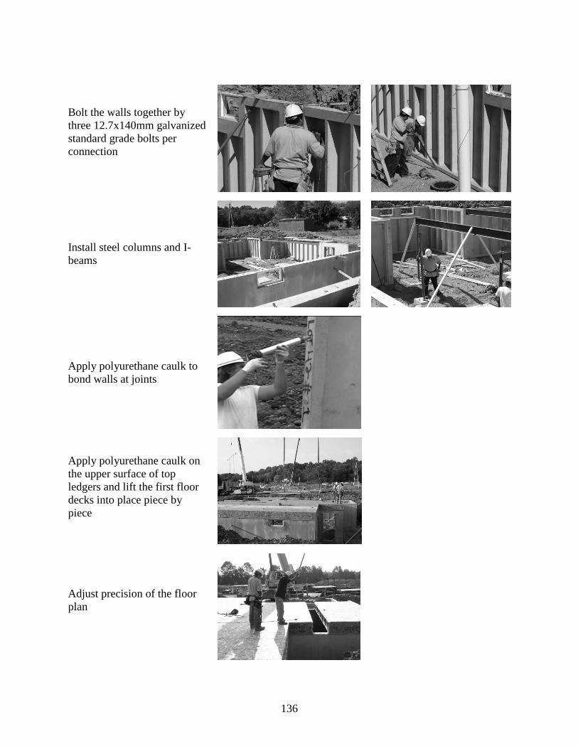
136
Bolt the walls together by three 12.7x140mm galvanized standard grade bolts per connection
Install steel columns and I-beams
Apply polyurethane caulk to bond walls at joints
Apply polyurethane caulk on the upper surface of top ledgers and lift the first floor decks into place piece by piece
Adjust precision of the floor plan
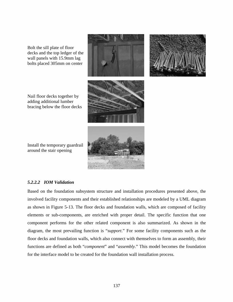
137
Bolt the sill plate of floor decks and the top ledger of the wall panels with 15.9mm lag bolts placed 305mm on center
Nail floor decks together by adding additional lumber bracing below the floor decks
Install the temporary guardrail around the stair opening
5.2.2.2 IOM Validation
Based on the foundation subsystem structure and installation procedures presented above, the
involved facility components and their established relationships are modeled by a UML diagram
as shown in Figure 5-13. The floor decks and foundation walls, which are composed of facility
elements or sub-components, are enriched with proper detail. The specific function that one
component performs for the other related component is also summarized. As shown in the
diagram, the most prevailing function is “support.” For some facility components such as the
floor decks and foundation walls, which also connect with themselves to form an assembly, their
functions are defined as both “component” and “assembly.” This model becomes the foundation
for the interface model to be created for the foundation wall installation process.

138
Figure 5-13: Facility Components and Their Relationships in Foundation Wall Installation
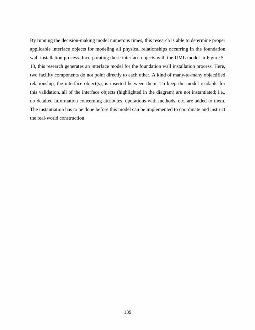
139
By running the decision-making model numerous times, this research is able to determine proper
applicable interface objects for modeling all physical relationships occurring in the foundation
wall installation process. Incorporating these interface objects with the UML model in Figure 5-
13, this research generates an interface model for the foundation wall installation process. Here,
two facility components do not point directly to each other. A kind of many-to-many objectified
relationship, the interface object(s), is inserted between them. To keep the model readable for
this validation, all of the interface objects (highlighted in the diagram) are not instantiated; i.e.,
no detailed information concerning attributes, operations with methods, etc. are added to them.
The instantiation has to be done before this model can be implemented to coordinate and instruct
the real-world construction.
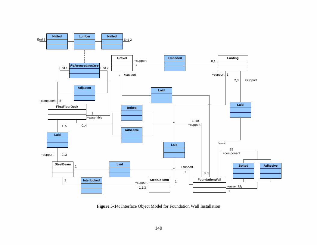
140
FoundationWall
Gravel Footing
+support
25
0..1
*2,3
0,1,2
1
SteelColumn
FirstFloorDeck
1
+support 1
+support 0..3
1..5 +support1..10
0..4
+support1
1
+support1,2,3
1
+assembly1
+component 8
+assembly
Embeded
Laid
Lumber NailedNailed
Laid
Laid
Interlocked
Laid
Laid
+component
+support
+support
0,1*
Bolted
Adhesive
AdhesiveBolted
ReferenceInterface
Adjacent
End 1 End 2
End 1 End 2
SteelBeam
Figure 5-14: Interface Object Model for Foundation Wall Installation

141
5.2.3 Componentized Superstructure Framing
5.2.3.1 Componentized Superstructure Framing Process
The componentized superstructure framing process is within the scope of framing package in the
superstructure subsystem. The process employs factory-made exterior integrated Structural
Insulated Panels (SIPs), interior metal-framed panels, floor decks, roof trusses, and Oriented
Strand Boards (OSBs). The integrated SIPs are a composite building material, which
incorporates OSB structural skins, polystyrene or polyurethane foam insulation, doors, windows,
electrical chase, and weatherproofing wrap. They offer better quality and performance than the
traditional site framed walls due to being manufactured in the well-controlled factory
environment. During installation, trained labor is required to handle complex physical interfaces
among SIPs and other facility components. For a typical 3,000 square feet single-family house,
the process normally takes three days for an eight-person crew and a crane to finish.
The framing process can be started after the foundation subsystem is finished. The framing
procedures are listed below and illustrated by photos:
Deliver exterior wall panels, interior wall panels, floor decks, and other building materials to the jobsite by truck
Set up the crane

142
Nail the OSB sheathing on gable end trusses and attach building wraps (sometimes, eave trusses are attached to the gable ends)
Install the sole plates for the first floor wall panels
Apply sealant on the sole plate Lift the first wall panel into place
Nail the panel with the sole plate Install the temporary lumber bracing
Install other wall panels on the first floor piece by piece and nail or screw them together
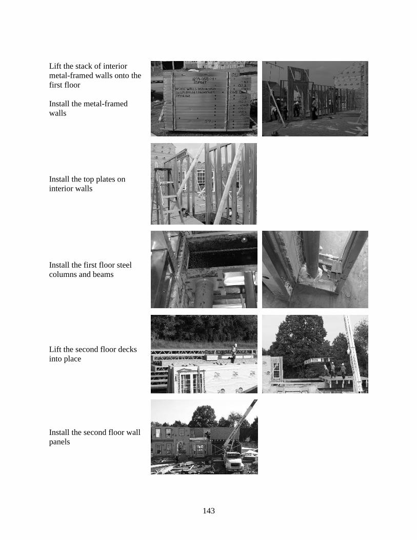
143
Lift the stack of interior metal-framed walls onto the first floor Install the metal-framed walls
Install the top plates on interior walls
Install the first floor steel columns and beams
Lift the second floor decks into place
Install the second floor wall panels
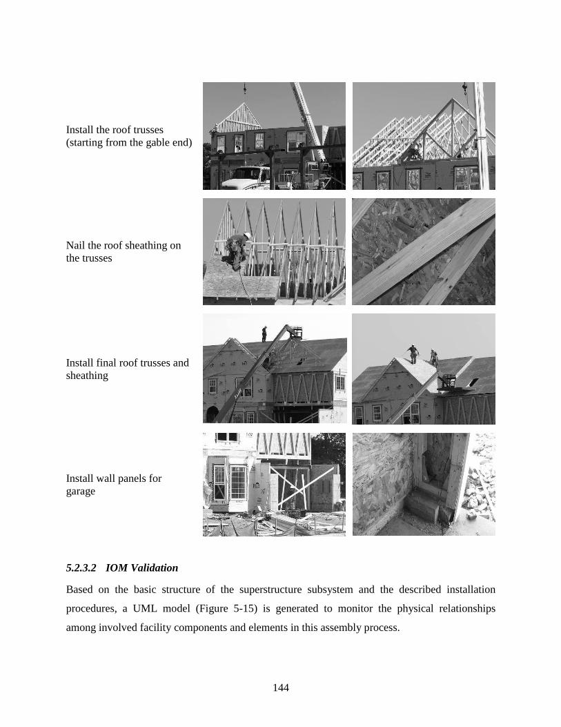
144
Install the roof trusses (starting from the gable end)
Nail the roof sheathing on the trusses
Install final roof trusses and sheathing
Install wall panels for garage
5.2.3.2 IOM Validation
Based on the basic structure of the superstructure subsystem and the described installation
procedures, a UML model (Figure 5-15) is generated to monitor the physical relationships
among involved facility components and elements in this assembly process.
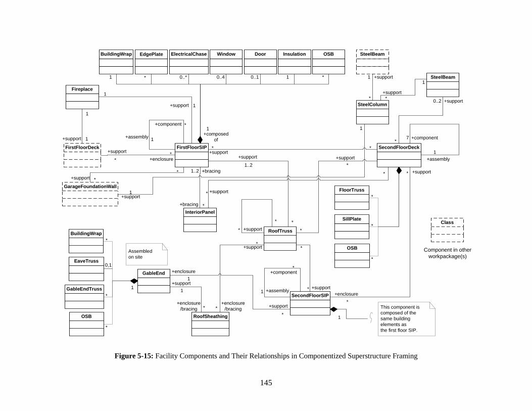
145
FirstFloorSIP SecondFloorDeck
InteriorPanel
SecondFloorSIP
SteelColumn
RoofTruss
RoofSheathing
Fireplace
FirstFloorDeck+support* *
+support0..2
*
+bracing
1..2
*
+support*
+support
**
*
+support*
1
+component
+assembly 1
*
+assembly1
+component7
Door Insulation
1
Window OSBElectricalChaseBuildingWrap
1 0..* 0..4 0..1 1 *
EdgePlate
*
FloorTruss
SillPlate
OSB
*
*
*
GarageFoundationWall
+support **
+support1
*
+support*
+enclosure*
+enclosure
+bracing
+component
+assembly1
*
1
This component is composed of the same building elements as the first floor SIP.
GableEnd0,1
BuildingWrap
GableEndTruss
OSB
*
*
*
Assembled on site
EaveTruss
1
+support
*
+support*
+enclosure1
+support*
+support1
+enclosure/bracing *
+enclosure/bracing*
+composed of
*
+support* *
+support*
*
1..2
+support
*
+support 1
1
+support 1
1
Class
Component in other workpackage(s)
+support1
1
SteelBeam
SteelBeam
Figure 5-15: Facility Components and Their Relationships in Componentized Superstructure Framing
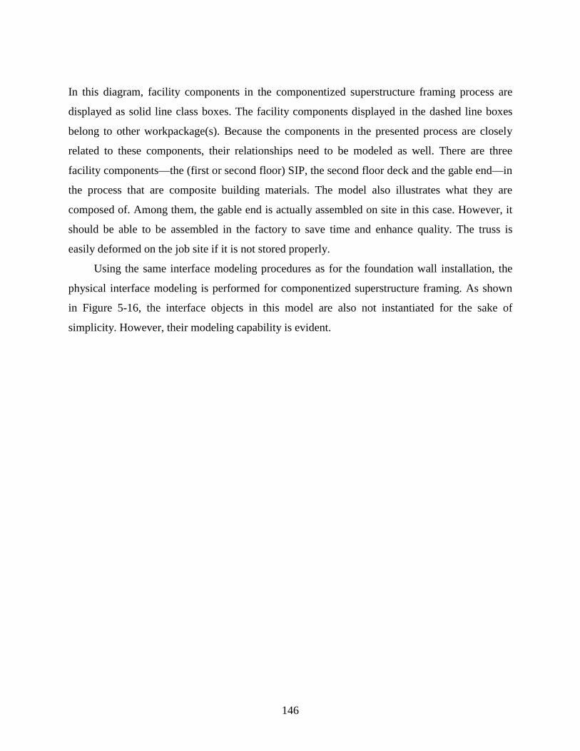
146
In this diagram, facility components in the componentized superstructure framing process are
displayed as solid line class boxes. The facility components displayed in the dashed line boxes
belong to other workpackage(s). Because the components in the presented process are closely
related to these components, their relationships need to be modeled as well. There are three
facility components—the (first or second floor) SIP, the second floor deck and the gable end—in
the process that are composite building materials. The model also illustrates what they are
composed of. Among them, the gable end is actually assembled on site in this case. However, it
should be able to be assembled in the factory to save time and enhance quality. The truss is
easily deformed on the job site if it is not stored properly.
Using the same interface modeling procedures as for the foundation wall installation, the
physical interface modeling is performed for componentized superstructure framing. As shown
in Figure 5-16, the interface objects in this model are also not instantiated for the sake of
simplicity. However, their modeling capability is evident.
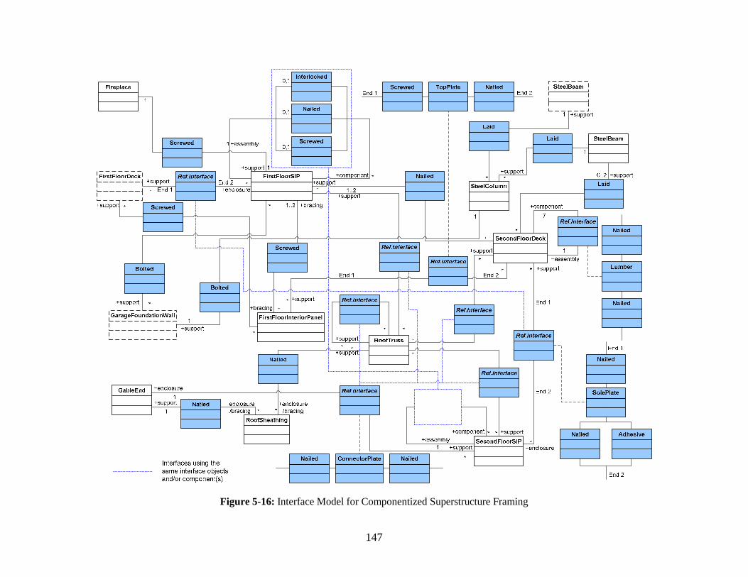
147
Figure 5-16: Interface Model for Componentized Superstructure Framing
148
5.3 BENEFITS AND POTENTIAL APPLICATIONS
The IOM data structure and interface object modeling method offer some benefits for presenting
comprehensive interface information which can enhance current building information models
(BIMs). Furthermore, potential model applications in the design and construction phases will
greatly improve overall project performance. Further explanation is presented below.
Firstly, the IOM and related interface object modeling provide a unified presentation of
interface information in the greatest detail. Through the validation of physical interface modeling
in building façade project examples and completed housing construction processes, it can be
proven that the proposed IOM works in real-world construction settings. Modeled interface
information is more accurate, and can be easily stored, exchanged, and applied to IT applications.
Secondly, the IOM enhances the completeness of modeled interface information in two
respects. On the one hand, it supplements the IFC object model, which is not capable of
presenting comprehensive interface information due to lack of a data structure for interface
information. The IOM is able to be seamlessly incorporated into the IFC as an added layer. As a
result, all product models based on the IFC will be given the capability to model comprehensive
interface information. On the other hand, through the concept of reference interface, the IOM can
model additional interface components. This will provide an interface components material list
for procurement. Such a list is often missed in current construction projects.
Thirdly—and perhaps the most significant future impact—this interface object modeling
method allows interface analyses during the design and construction phases. These interface
analyses, never existing before, can test different design solutions and the incorporated types of
interfaces in design and construction against risk, cost, time, and any other management concerns.
Potential applications may include but are not limited to:
A design tool for improving construction performance through interface optimization:
Physical interface modeling in the design phase can help track the total number of interfaces,
the involved interface objects, and the additional interface components. Optimization can
therefore be performed by minimizing the number and the complexity of physical interfaces
in a project. Although the number is not a sole standard for judging the complexity of
interfaces, it can provide very important information for such a judgment. For example, in
149
the design phase, by selecting factory-made facility components instead of raw building
materials, designers can effectively reduce the number of interfaces that need to be specially
designed and executed later on the construction site. Consequently, interface related
operations will be limited; quality control and IM can be easier.
A structural method to determine interface-friendly workpackaging and
subcontracting: Through interface object modeling, different types of interfaces between or
in relation to two facility components can be monitored. According to the complexity of
such interfaces, it will be determined whether these two components can be separately
assigned to different workpackages and built by different contractors. Usually, interface-
friendly workpackaging and subcontracting attempt not to break complex interfaces in
construction projects. This can avoid intensive information coordination and interactions
across boundaries of project participants.
An enhanced view for BIMs: Interface object modeling adds detailed interface information
to current BIMs for simulation and coordination. This greatly enhances the BIMs’
completeness and capability of coordinating and controlling interfaces. Especially for visual
4D models which incorporate 3D CAD models with construction activities to display the
construction progress over time, detailed interface information will help trigger sequential
construction activities only when the prerequisite conditions for specific interfaces are
satisfied. The enhanced simulation will provide more accurate project progress over time in
the real-world construction setting or environment. Based on such models, the breadth and
depth of coordination can be increased. Project performance in terms of interfaces will be
optimized.
150
CHAPTER 6: SYSTEMATIC MODEL-BASED INTERFACE MANAGEMENT
This chapter presents a conceptual, systematic model-based interface management (IM) strategy
for integrated project delivery (IPD), especially design-build that facilitates extensive interface
information sharing, coordination, and provides the best opportunity for BIM approaches. This
strategy provides a good foundation for creating an implementation environment for the
proposed interface object modeling technique. Its development consists of three consecutive
steps: 1) propose the main IM sub-processes that aim to deal with various types of interface
issues in a complete project process; 2) develop the interface modeling core that combines the
Interface Object Model (IOM) and the Building Information Modeling (BIM) approach; and 3)
incorporate the modeling core into the project process for more effective and efficient IM. This
chapter also briefly discusses how this IM strategy works in general and what specific functions
the interface modeling core performs in the project process. This conceptual work needs further
development for its implementation.
6.1 INTRODUCTION TO THE STRATEGY
As discussed earlier, in the literature, most of the proposed IM strategies and tools are aimed at
resolving specific interface issues. Scattered improvements in the project processes do not
significantly enhance overall project performance and the quality of the final product (the built
facility) in terms of interfaces. This research proposes a systematic IM strategy that will make a
difference. This strategy is presented as an integrated process flow chart.
The strategy employs systems engineering thinking. It aims to cover a complete project
process (regarded as a project system) where sub-processes are interacting components; e.g.,
poorly performed preceding processes can adversely affect succeeding processes in some way(s).
All of these sub-processes are contributing to overall project performance (e.g., against schedule
and budget). On the other hand, different types of interfaces (physical, functional, contractual,
organizational, and resource interfaces) in the system are interrelated. They should be
coordinated and controlled as a whole to improve IM performance as well as overall project
151
performance. That is to say, IM activities involved in different sub-processes are all very
important and need to be performed at the same level of efficiency.
Due to the large number of interfaces and their complexity in a construction project, the
strategy is IT oriented—extensively incorporating IT tools into the IM process. First, various
interfaces with comprehensive interface information are accurately modeled using an object-
oriented modeling language; this depends on the interface modeling core for which the IOM is
the backbone. The core also relies on current BIM approaches to model facility components and
related project information. Second, the modeled information is stored, coordinated, and
implemented by appropriate IT tools that are seamlessly incorporated into the IM and project
processes.
The strategy’s goal can be achieved to its fullest potential when a project uses an IPD
method (such as design-build or engineer-procure-construct) where IM can be performed and
coordinated extensively due to the highest degree of integration of design, planning,
manufacturing, and construction activities. Also, a design-build process, in which a BIM can be
easily shared between design and construction professionals, can achieve greater benefits from
BIM approaches (AutoDesk, Inc. 2002). In contrast, for the traditional project delivery (e.g.,
design-bid-build) or fast tracking methods, the strategy faces great difficulties due to lack of
communication and coordination among parties who have no direct contracting relationships.
Also, BIM approaches hardly work since the delivery process depends largely on subcontractor
involvement during design development (Post 2006). However, if adequate communication and
coordination can be achieved and subcontractors’ design information can be incorporated into a
BIM (Building Information Model) as early as possible, the strategy’s benefits can still be
realized. Successful IM will help achieve a win-win relationship among project participants as
well as optimize overall project performance.
6.2 CONCEPTUAL DEVELOPMENT
The conceptual development of the strategy is based on an IPD process, in particular, design-
build. It implements three consecutive steps. These steps and their results are introduced in the
following subsections.

152
6.2.1 IM Sub-Processes for a Complete Project Process
In practice, a typical design-build project delivery process may be composed of the following
five main phases, namely Project Definition and Conceptual Design, Detailed Design,
Subcontract, Plan and Schedule, and Construction and Assembly. IM is usually considered in the
detailed design and construction and assembly phases. In this research, the proposed IM strategy
aims to cover a complete project process that extends the traditional project delivery process into
a sixth phase called Operation, Maintenance, Retrofit, and Salvage. These phases are introduced
later in this chapter. Now, IM starts at the very beginning of the project—the project definition
and conceptual design phase—and continues till the final operation, maintenance, retrofit, and
salvage phase. Figure 6-1 shows the concept of the new IM strategy.
Project definition & conceptual
designDetailed design
Subcontract for suppliers/offsite manufacturers/ subcontractors
Plan & schedule
Construction & assembly
Operation, maintenance,
retrofit & salvage
The Traditional Project Process
Interface Management
The Complete Project Process
Project definition & conceptual
designDetailed design
Subcontract for suppliers/offsite manufacturers/ subcontractors
Plan & schedule
Construction & assembly
Operation, maintenance,
retrofit & salvage
The Traditional Project Process
Interface Management
The Complete Project Process
Figure 6-1: The New IM Strategy for a Complete Project Process
Through a literature review (Chapter 2) and an interface-related built environment analysis
(Chapter 3), numerous interface issues in those project phases have already been revealed. The
needs for IM can be envisioned. This research proposes several main IM sub-processes to meet
such needs. These processes must be appropriately incorporated into the complete project
process to improve IM performance. Figure 6-2 is an integrated project process flow chart that
combines the proposed IM sub-processes with project sub-processes. The notations are explained
in Table 6-1.
In the following, each of these project phases is briefly introduced, followed by a
discussion of the IM needs and the proposed IM sub-processes in that phase.

153
Figure 6-2: IM Sub-processes in a Complete Project Process
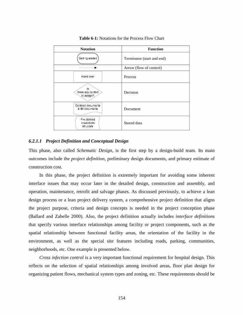
154
Table 6-1: Notations for the Process Flow Chart
Notation Function
Terminator (start and end)
Arrow (flow of control)
Process
Decision
Document
Stored data
6.2.1.1 Project Definition and Conceptual Design
This phase, also called Schematic Design, is the first step by a design-build team. Its main
outcomes include the project definition, preliminary design documents, and primary estimate of
construction cost.
In this phase, the project definition is extremely important for avoiding some inherent
interface issues that may occur later in the detailed design, construction and assembly, and
operation, maintenance, retrofit and salvage phases. As discussed previously, to achieve a lean
design process or a lean project delivery system, a comprehensive project definition that aligns
the project purpose, criteria and design concepts is needed in the project conception phase
(Ballard and Zabelle 2000). Also, the project definition actually includes interface definitions
that specify various interface relationships among facility or project components, such as the
spatial relationship between functional facility areas, the orientation of the facility in the
environment, as well as the special site features including roads, parking, communities,
neighborhoods, etc. One example is presented below.
Cross infection control is a very important functional requirement for hospital design. This
reflects on the selection of spatial relationships among involved areas, floor plan design for
organizing patient flows, mechanical system types and zoning, etc. These requirements should be

155
specified in the interface definitions, which enhance the conceptual design with better interface
features. Hence, it becomes easier for the detailed design to satisfy such functional requirements.
Since the lack of (or inadequate) interface definition may cause serious interface issues, the
presence of interface definition is emphasized in the strategy.
In order to define main physical and functional interfaces in a facility more adequately and
accurately, a decomposition of the facility is needed. This strategy proposes to use a pre-defined
breakdown structure (functionality-based) because a decomposition based on systems or
functions has been regarded superior to the traditional WBS in defining interfaces (Laan et al.
2000; Miles and Ballard 2002).
6.2.1.2 Detailed Design
This phase usually includes two sub-phases: Design Development and Construction Documents.
In this phase, the approved schematic design is continuously developed to generate the detailed
floor plans, elevations, sections, the specification outline defining materials, finishes, and facility
elements/components/systems, as well as the updated construction cost estimate. After these
documents are approved, comprehensive construction drawings and specifications are developed.
During detailed design, all physical and functional interfaces should be carefully considered,
accurately defined, and closely coordinated to ensure that construction documents are adequate,
error-free, and constructible.
Based on such a need, a special IM sub-process for checking physical and functional
interface conflicts is added into the detailed design phase. This sub-process may be aided by 3D
visualization techniques, object-oriented CAD tools, or BIM approaches. The identified interface
conflicts in design can be corrected automatically or manually. Simultaneously, the interface
specifications, as one part of project specifications, are also provided. Here, IM performance of
checking and correcting interface conflicts is highly dependent on the effectiveness of modeling
and computer programming as well as the skill and experience of a design-build team.
6.2.1.3 Subcontract
At present, most construction projects are subcontractor-based. It is very common for 20 to 30
subcontractors to be employed on a single project, like the stick-build homebuilding process
mentioned earlier, which involved 21 subcontractors. Also, the selected subcontractors may have
156
no previous working experience with each other in handling similar construction projects. Their
project performance varies and greatly affects the construction and assembly phase.
Prior to subcontracting, the project work scope is usually decomposed into facility elements
and/or components based on the selected breakdown structure. Then these elements and/or
components are regrouped into different workpackages that are ready for subcontracting. The
subcontracting strategy has great influence on interfaces and IM. For example, a poor
subcontracting strategy breaks the large number of physical and functional interfaces into
different contracts, which leads to intensive coordination for interface parameter information (if
subcontractors need to do some detailed design) and on-site activities. This further complicates
the relationships among subcontractors and increases the difficulties in their operations.
Therefore, this research considers subcontract a distinguishable project phase for IM.
The proposed strategy adopts the functionality-based breakdown structure used in the
schematic design phase, and identifies interface-friendly workpackages for subcontracting; i.e.,
to keep the complex interfaces in a single contract and/or reduce the number of interfaces that
may be broken into different contracts. On the other hand, during subcontracting, work scopes
and specific interface responsibilities for subcontractors need to be precisely defined. This
information should be written into contracts. If necessary, additional IM documents need to be
provided for subcontractors to handle complex interfaces within or related to their scopes of
work.
6.2.1.4 Plan and Schedule
The plan and schedule phase is right before the construction starts. According to Hendrickson
and Au (2003), the involved tasks in this phase consist of:
The selection of technology and construction method
The definition of work tasks
The estimation of required resources and durations for individual activities
The identification of interactions among different work tasks
The development of cost and time schedules
This phase provides a very good opportunity for the design-build team and subcontractors to
establish their relationships and coordinate their construction plans and schedules. However, in
157
practice, this opportunity is not fully utilized by project participants. Usually, their working
relationships are relatively loose and coordination may stay only on the schedule level. In fact, a
successfully conducted plan and schedule phase should be able to establish the best working
relationships among participants prior to the real construction. These relationships include
effective and efficient communication channels, clarified and accepted coordination
responsibilities, and the willingness to share various resources and cooperate closely. Also, the
success of this phase includes extensive coordination among participants’ detailed construction
plans and schedules. This avoids and minimizes potential construction related interface issues
later.
The strategy proposes an IM sub-process to check contractual, organizational, and resource
interfaces among involved contractors for potential conflicts. The purpose is to enhance their
working relationships and optimize site organization, material supply, resource allocation, work
sequence, and working environment for construction activities. The outcomes are the
coordinated schedules and interface documents. It is worth noting that during construction the
schedule coordination should be executed frequently among the updated schedules of
subcontractors to determine the proper relationships among the real statuses of work progress.
6.2.1.5 Construction and Assembly
This phase is the constructing and/or assembly of facility elements, components, and subsystems
on the jobsite according to construction documents. It is the most complex project phase due to
the numerous parties involved and the ever-changing environments. On the other hand, interface
conflicts in design, usually unnoticeable in the design phase, arise in construction. In addition,
poor construction quality, material supply, resource utilization, schedule control, etc. can cause
many defects or failures that increase construction costs and delays.
If potential interface conflicts in design, inter-party working relationship, construction plan
and schedule are not identified, coordinated, and corrected in the previous project phases, the IM
needs in the construction and assembly phase will become significantly more complex. It will be
extremely difficult to perform IM successfully. Fortunately, the IM sub-processes added into
those preceding phases have eliminated many potential interface issues and hence reduced the
158
complexity of interfaces in the succeeding phases. As a result, interface management and control
in this phase focus mainly on quality and safety control.
The IM sub-process—checking quality of interfaces—is integrated into this phase. Here,
mainly physical interfaces (e.g., physical connections, spatial relationships, and construction
methods) and resource interfaces (e.g., workplace organization, equipment operation, and
environment) are checked. Any defects or failures need to be corrected. Then project
commissioning before handover is employed to check functional interfaces for facility
subsystems. Information obtained through commission may be used to form a good strategy for
the formal operation after occupancy.
6.2.1.6 Operation, Maintenance, Retrofit, and Salvage
Conventionally, the operation, maintenance, retrofit, and salvage phase is not considered part of
the project delivery process, or is included in a very limited way. It belongs to the scope of
facility management. Nevertheless, many aspects of this phase are found to be related to the
project delivery process in terms of interfaces. For example, the choice of building materials
determines the life cycle of such materials for maintenance. The selection of facility subsystems
and their functional interfaces decides the operation procedures and strategies to keep the energy
efficiency of a facility. The quality of physical interfaces influences the frequency of repair and
replacement of operational parts in a facility. Therefore, this research incorporates this phase into
the complete project process for IM.
Besides the interface operation and maintenance (O & M) documents provided by the
construction and assembly phase and the information obtained from the facility commissioning
before handover, this phase is also dependent on a commissioning during occupancy and
operation to find out the best operation strategy for optimizing systems performance and
achieving energy efficiency. The facility subsystems (e.g., lighting system and mechanical
system) may also be adapted during occupancy (due to changes in use) or retrofitted if needed.
All the changes may alter interface O & M procedures, and therefore need to be documented.
The updated interface O & M documents are usually generated for future use.
To achieve the best IM performance as well as overall project performance, all these IM
sub-processes need to be performed effectively and efficiently. The aid of interface modeling and

159
automatic interface coordination in the complete project process is necessary. The following
subsection introduces how an interface modeling core is built based on the proposed IOM.
6.2.2 The Interface Modeling Core
The interface modeling core represents a powerful modeling engine for the systematic IM
strategy. Several functions for this modeling core are defined as follows:
Accurately model comprehensive interface information for various types of interfaces in
construction projects
Automatically check conflicts and coordinate interface information
Quickly respond to queries for interface information and IM procedures
Instantly give notice of IM needs for certain activities to the involved participants
Generate comprehensive IM documents and guidelines
Based on these functional requirements, this research builds an interface modeling core. As
shown in Figure 6-3, this modeling core combines the IOM and current BIM approaches. There
are four important components: the IOM, the Interface Databases, the Building Information
Modeling Environment (BIME), and the generated Building Information Model (BIM). How
these model components are related to each other and how interface modeling can be performed
are explained here.
A fully developed IOM will present the complete data structure and data dependencies for
interface information. Based on the IOM, the interface databases (the structured collection of
interface information) can be created. According to the research needs, the databases can be
object-oriented; this feature acts as a bridge to connect the database world and the object-
oriented programming world. The databases can also be XML-based; they store all the
documents and data (from individual organizations’ information resources) in one place for
application. In practice, the interface databases can be provided by different sources. Servers are
needed to provide database services to various computers or computer programs. Also, the IOM
by itself can evolve into an interface modeling tool that incorporates the interface modeling
application software with the IOM data model. It can access interface information from the
databases. An IM handbook, as one main outcome, can be generated. This research, however,
chooses to mainly utilize the powerful BIM approaches for interface modeling and coordination.

160
Interface Databases
Servers
Building Information Model
(including the interface model)
Building Information Modeling Environment (BIME)
Modeling application softwareGeometry-based CAD modeling+ Object-oriented CAD modeling+ Parametric building modeling
+ Interface modeling
Workstations Modeling personnel
IOM (Interface
Object Model)
IFCs aecXML ...
modeling
processing
Develop Software
Generate IM
Handbook
Figure 6-3: The Interface Modeling Core
The BIME integrates the current BIM environment with the interface object modeling technique.
The current BIM environment consists of 1) the BIM application software (e.g., ArchiCAD,
Bentley Architecture, or Autodesk Revit), 2) workstations, and 3) modeling personnel. It is based
on the data structure provided by the IFC or other data models. The current BIM application
software employs technologies of geometry-based CAD, object-oriented CAD, and parametric
building modeling. The interface object modeling technique is added into the software as plug-
ins or extensions.
The interface modeling can be performed during BIM (e.g., after two building components
are modeled, their interface(s) is/are modeled right away) or after BIM (e.g., after all the building
components are modeled, their interfaces are modeled together). During modeling, the BIME
161
accesses the IOM and interface databases (through the IOM) for data structure and interface
reference information. The generated BIM includes the traditional BIM and an interface model.
In the modeling core, the IOM acts as the backbone; the BIME is the kernel; and the
generated BIM is a repository that holds complete, intelligent, multi-perspective project
information including interface information. The enhanced BIM not only performs coordination
functions but also provides compatible information for modeling, processing, operation, and
decision-making. In the following subsection, this modeling core is incorporated into the IM
integrated project process proposed above.
6.2.3 Systematic Model-Based IM
Early in this chapter, the proposed IM sub-processes are integrated into a complete project
process for systematic IM. However, the effectiveness and efficiency of these IM sub-processes
are questioned due to the complexity of interfaces and interface issues. The importance of
interface modeling, automatic interface coordination and IT-aided IM is emphasized.
Accordingly, an interface modeling core is created and presented. This subsection aims to
incorporate the modeling core into the complete project process to assist IM. The incorporation
should answer the following questions:
When the interface modeling core should be incorporated into the systematic IM process;
What project/IM sub-processes should be connected with the modeling core; and
How the interface information flows between the modeling core and these sub-processes.
Figure 6-4 shows a new integrated process flow chart to illustrate the incorporation. The process
flow chart includes the previous flow chart (shown in Figure 6-3) that presents how the proposed
IM sub-processes are integrated into the complete project process. It also includes the simplified
modeling core that shows the four model components only. The modeling core and project/IM
sub-processes are connected by interface information flows, which are displayed as the dashed
lines. The thick dashed lines represent information (to be modeled) flowing into the modeling
core; the thinner dashed lines denote information (stored in the BIM and/or the IOM) that flows
out of the modeling core to the corresponding sub-processes and will be implemented there. In
the following section, how the IM strategy works in general and what specific functions the
modeling core performs are discussed.

162
Figure 6-4: Systematic Model-Based IM Process Flow Chart

163
6.3 DISCUSSION OF APPLICATIONS
Up to now, the view of the systematic model-based IM strategy has been completed. The
integrated process flow chart (shown in Figure 6-4) has successfully incorporated the proposed
IM sub-processes and the interface modeling core into a complete project process that employs
the design-build delivery method. In this section, how the IM strategy works in general and what
specific functions the interface modeling core performs over time are discussed.
As shown in the flow chart, the modeling core is first used in the project definition and
conceptual design phase to accurately define main physical and functional interfaces of a facility.
At this stage, the BIM has not been built. Designers make queries to the IOM for interface
definition information based on the type of facility to be designed, the environment the project
faces, and the specific requirements from the client. Then, the IOM together with the connected
interface databases provide compatible information to support this task.
The outcomes of this task are the interface definitions, which accurately define all the
important physical and functional interfaces of a facility. The definitions are used to direct the
subsequent conceptual design in the choice of facility plan, orientation, and/or MEP (mechanical,
electrical, and plumbing) systems. Hence, the conceptual design can include all important
interface features for design development performed later. The definition information is also
incorporated into the IOM to enrich the connected databases and prepare the physical and
functional interface modeling. During the task—performing conceptual design—the preliminary
design information starts to be entered into the BIME for modeling. From now on, the BIM is
built and will be updated continually as the project evolves over time. At this stage, information
stored in the BIM can be used for energy analysis by using tools such as EnergyPlus. According
to Khemlani (2006), the use of BIM in the schematic design phase can provide the platform for
early integration of architectural, structural, and MEP designs.
The use of the modeling core in the detailed design phase starts with the task—performing
detailed design. The design process is actually a modeling process. Information stored in the
BIM directs design development, which, in turn, instantly records the design progress and
updates the stored information. With the increasing use of BIM approaches in the industry, the
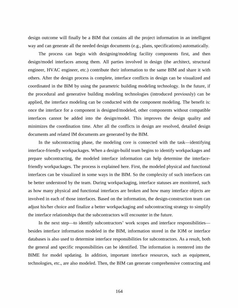
164
design outcome will finally be a BIM that contains all the project information in an intelligent
way and can generate all the needed design documents (e.g., plans, specifications) automatically.
The process can begin with designing/modeling facility components first, and then
design/model interfaces among them. All parties involved in design (the architect, structural
engineer, HVAC engineer, etc.) contribute their information to the same BIM and share it with
others. After the design process is complete, interface conflicts in design can be visualized and
coordinated in the BIM by using the parametric building modeling technology. In the future, if
the procedural and generative building modeling technologies (introduced previously) can be
applied, the interface modeling can be conducted with the component modeling. The benefit is:
once the interface for a component is designed/modeled, other components without compatible
interfaces cannot be added into the design/model. This improves the design quality and
minimizes the coordination time. After all the conflicts in design are resolved, detailed design
documents and related IM documents are generated by the BIM.
In the subcontracting phase, the modeling core is connected with the task—identifying
interface-friendly workpackages. When a design-build team begins to identify workpackages and
prepare subcontracting, the modeled interface information can help determine the interface-
friendly workpackages. The process is explained here. First, the modeled physical and functional
interfaces can be visualized in some ways in the BIM. So the complexity of such interfaces can
be better understood by the team. During workpackaging, interface statuses are monitored, such
as how many physical and functional interfaces are broken and how many interface objects are
involved in each of those interfaces. Based on the information, the design-construction team can
adjust his/her choice and finalize a better workpackaging and subcontracting strategy to simplify
the interface relationships that the subcontractors will encounter in the future.
In the next step—to identify subcontractors’ work scopes and interface responsibilities—
besides interface information modeled in the BIM, information stored in the IOM or interface
databases is also used to determine interface responsibilities for subcontractors. As a result, both
the general and specific responsibilities can be identified. The information is reentered into the
BIME for model updating. In addition, important interface resources, such as equipment,
technologies, etc., are also modeled. Then, the BIM can generate comprehensive contracting and
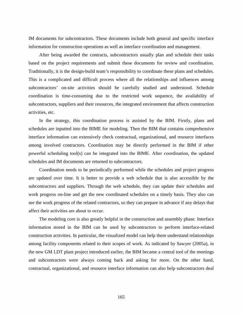
165
IM documents for subcontractors. These documents include both general and specific interface
information for construction operations as well as interface coordination and management.
After being awarded the contracts, subcontractors usually plan and schedule their tasks
based on the project requirements and submit these documents for review and coordination.
Traditionally, it is the design-build team’s responsibility to coordinate these plans and schedules.
This is a complicated and difficult process where all the relationships and influences among
subcontractors’ on-site activities should be carefully studied and understood. Schedule
coordination is time-consuming due to the restricted work sequence, the availability of
subcontractors, suppliers and their resources, the integrated environment that affects construction
activities, etc.
In the strategy, this coordination process is assisted by the BIM. Firstly, plans and
schedules are inputted into the BIME for modeling. Then the BIM that contains comprehensive
interface information can extensively check contractual, organizational, and resource interfaces
among involved contractors. Coordination may be directly performed in the BIM if other
powerful scheduling tool(s) can be integrated into the BIME. After coordination, the updated
schedules and IM documents are returned to subcontractors.
Coordination needs to be periodically performed while the schedules and project progress
are updated over time. It is better to provide a web schedule that is also accessible by the
subcontractors and suppliers. Through the web schedule, they can update their schedules and
work progress on-line and get the new coordinated schedules on a timely basis. They also can
see the work progress of the related contractors, so they can prepare in advance if any delays that
affect their activities are about to occur.
The modeling core is also greatly helpful in the construction and assembly phase. Interface
information stored in the BIM can be used by subcontractors to perform interface-related
construction activities. In particular, the visualized model can help them understand relationships
among facility components related to their scopes of work. As indicated by Sawyer (2005a), in
the new GM LDT plant project introduced earlier, the BIM became a central tool of the meetings
and subcontractors were always coming back and asking for more. On the other hand,
contractual, organizational, and resource interface information can also help subcontractors deal

166
with other project participants as well as organize the required resources and workplace
interfaces. In addition, detailed information (interface attributes, operations, etc.) modeled in
interface objects can be the most important references for subcontractors’ interface operations
and quality control.
After an interface is fulfilled, the interface status in the BIM is updated through the BIME.
Then, the new BIM can be employed in checking quality of interfaces by inspectors. If
inspections are all passed, interface O & M documents are finalized and handed over to the
owner or owners’ facility management personnel.
In the last project phase, the BIM can be used to determine interface O & M strategies.
Systems performance (energy) simulation and evaluation for all proposed strategies can be
conducted based on comprehensive functional interface information modeled in the BIM. Based
on the results, the best strategy can be chosen. Physical interface O & M information can help
determine when the operational parts in a facility need to be repaired or replaced and which types
of new parts are compatible with the old facility system. The interface O & M data, records and
best practice are entered into the BIME to update the BIM.
After a certain period of time, a facility will be retrofitted and some physical and functional
interfaces will be changed. Accordingly, the O & M strategy needs to be adjusted to
accommodate the changes. The above process will be performed once again. No matter how
many times retrofits are conducted, the BIM is always updated to contain the history of and the
latest interface information.
The use of the interface modeling core permeates the whole project process from beginning
to end. The BIME supports uninterrupted exchanges of interface information with involved sub-
processes and instantly updates the BIM to reflect real project status. The BIM can be
implemented in different project/IM sub-processes for designing, constructing, coordinating and
managing various interfaces. Accurate interface documents are also generated from the BIM to
assist the IM process. This systematic model-based IM strategy is highly effective and efficient
for handing a large number of interfaces in multi-disciplinary projects that employ IPD methods.

167
It is worth noting that this IM strategy is only conceptually developed. Future research
should focus on developing the modeling core, specifying detailed IM procedures, and
demonstrating the strategy via real-world applications.

168
CHAPTER 7: CONCLUSIONS AND RECOMMENDATIONS
7.1 RESEARCH FINDINGS
Interface management (IM) is an emerging area of project management in the construction
industry. It is extremely important for multi-disciplinary construction projects including
infrastructure design and construction, sustainable development, and building construction.
Properly managing interfaces among the client, developers, designers, contractors, government
agencies, environments, or facility/project components, is essential to project success. This
research helps establish the importance of IM in the construction industry, and inspires
comprehensive interface-related research to be performed widely and promptly.
Specifically, this research aims to enhance the industry’s overall project performance by
improving interface modeling through systematic model-based IM. The most important
contribution is the Interface Object Model (IOM) framework that presents the data structure and
dependencies of interface information for object modeling. The following subsections conclude
the main research findings (contributions).
7.1.1 A Multi-Perspective Analysis
This research conducted a multi-perspective analysis to explore comprehensive cause factors of
interface issues in the current built environment. This analysis adopted the method of the Cause-
and-Effect diagram and identified six interrelated perspectives (People/Participants,
Methods/Processes, Resources, Documentation, Project Management, and Environment) as main
cause areas. From these perspectives, 155 cause factors (including major causes, minor causes,
and sub-factors) of various interface issues were explored and presented in a well-structured,
hierarchical way. The cause factors can be directly converted into success factors for IM.
To represent the cause factors in a more applicable format, this research transformed them
into a series of interface management and control elements within affinity diagrams. These
elements were helpful in developing the Interface Object Hierarchy diagram for the proposed
IOM framework, and can be used in future research in other ways as well. This multi-perspective

169
approach contributed a holistic understanding of interface issues to the literature and built a
theoretical foundation for researchers and practitioners to seek all-around IM solutions.
7.1.2 A Comprehensive IOM Framework
This research initiated an object view of interfaces, and defined a unified way of presenting
interface information. Consequently, in the object-oriented modeling environment, interfaces
become a collection of active objects that react to outside requests and automatically perform
complex operations. These objects can play a very important role in model-based interface
coordination, management, and operation.
To support the proposed interface object modeling, the data structure and dependencies of
interface information were defined in an IOM framework. This framework consists of two levels.
The Modeling Level presents the basic interface data structure in a hierarchy; the Application
Level illustrates the data dependencies (contextual relationships) between interface information
and other well-known project information. There are five model components within the
framework, including Interface Categorization, Interface Object Hierarchy, UML Interface
Object Class Diagrams, System Data Dependency, and Relational Diagrams. They have been
developed into different levels based on the research needs.
This interface data model is the first in the literature. When fully developed in future
research, the IOM will have broad applications in interface design, construction, and
management. Specifically, it helps project participants build a comprehensive understanding of
various interfaces within their scopes of work. It also helps create interface databases to improve
future modeling and decision-making. Most importantly, accurate, standardized, and model-
based interface information can be easily adopted by an IT-oriented IM process for managing
and controlling a wide variety of interfaces in construction projects and preventing potential
interface issues.
7.1.3 A Systematic Model-Based IM Strategy
This research conceptually developed a systematic model-based IM strategy that employs
systems engineering thinking. The strategy targets all kinds of interface issues as a whole and
covers a complete project process for IM. Due to the complexity of interface information and the
170
difficulties in performing effective and efficient IM, an interface modeling core is created and
incorporated into the project process. This modeling core, backed by the IOM and Building
Information Modeling (BIM) approaches, can model and handle large amounts of interface
information to improve IM performance as well as overall project performance in the
construction industry. This strategy has established a good foundation for creating an
implementation environment for the proposed interface object modeling.
7.1.4 IM Benefits
Effectively executed IM can be of great benefit to construction projects. Through this research
development, potential IM benefits can be concluded as follows:
Build a deep understanding of project complexity for project participants
Optimize design in terms of quality, compatibility, constructability, cost, risk, and function
to meet customer needs
Improve project planning by avoiding, minimizing, or eliminating potentials for interface
issues in advance
Improve workpackaging and subcontracting to reduce project complexity and to avoid
inherent interface issues
Build and maintain desirable relationships and interaction channels among project
participants to achieve timely communication, coordination, and cooperation
Standardize handling processes and work flows for various types of interfaces in
construction projects and reduce uncertainties
Enable a dynamic and well-coordinated construction project delivery system when
responding to changes
Identify and record good practices in dealing with project complexity and reapply them in
future projects
Much effort is required to fully achieve these IM benefits. The author of this dissertation plans to
perform future research in the following directions, which will not only further develop this
research into an application level but will also build valuable connections with other relevant
efforts in the literature and in construction practice.

171
7.2 RECOMMENDATIONS FOR FUTURE RESEARCH
Considering the enormous variety of interfaces and the severity of interface issues in multi-
disciplinary construction projects, the author believes that applications of this research are
unlimited. However, despite the several aforementioned research findings (contributions), this
research needs further development to achieve its full implementation. For the short term, the
planned research will target four tasks.
7.2.1 Further Development of the IOM
The first task is to further develop the IOM into an application level and incorporate it into 3D or
4D BIM. The objective is to promote the IOM’s implementation and simultaneously enhance
BIM capabilities to model and coordinate various types of interfaces as well as to guide field
interface operations. This task is most important and has the highest priority in the research plan.
At present, this research has studied modeling physical interfaces. A software prototype,
which incorporates physical interface modeling with BIM approaches, needs to be built. In the
prototype, the IOM’s capabilities of modeling physical interfaces and directing the visualization
of related interface handling procedures (as shown in Figure 7-1) will be tested. At the same time,
ways of using the modeled information for design, construction, and project management and
control will also be uncovered. The application will be to improve the componentized
homebuilding process.
As presented in this dissertation, information that can be modeled in interface objects
includes interface attributes, operations with methods, responsibilities, etc. This information
supports various modeling functions of interface objects. In the planned research, potential field
operations for those applicable physical interface objects will be accurately defined based on the
knowledge of construction and the well-developed classification/taxonomy of construction
operations (Everett 1994, Al-Masalha 2004). The operations will then be visualized and linked
with corresponding interface objects. In response to outside requests, those interface objects will
direct the model to display the linked visualization or simulation, which helps disclose potential
conflicts and guide field operations to be performed in a more accurate and efficient way.

172
Figure 7-1: Interface Modeling Capabilities of the Prototype
At the early stage, the visualization will use an icon-based prototyping methodology that
“develops a graphic heuristic for industrialized assembly and suggests a new taxonomy for
designing construction operations and presenting those designs to the field” (Johnston et al.
2006). This method describes each operation/task in the still-frame animation format to enhance
understanding. Within each activity frame, Operation, Component, and Resource windows hold
constituent icons attributable to the operation/task. Those icons are active in task analysis and
sequencing. This iconic construction language is still under development by Brendan Johnston, a
Ph.D. candidate in the Building Construction Department at Virginia Polytechnic Institute and
State University. However, its benefit to presenting interface operations can be envisioned.
After building this software prototype for physical interface modeling, future research will
develop it to model other categories of interfaces from functional, organizational/contractual, to
resource interfaces. Since applicable interface objects within these categories have not been
defined in the current IOM framework, future work will first develop them into the applicable
Object-OrientedInterface Modeling
Procedures Visualization
Testify IOM’s capability of modeling physical interfacesand linking the visualization of construction procedures
Object-OrientedInterface Modeling
Procedures Visualization
Testify IOM’s capability of modeling physical interfacesand linking the visualization of construction procedures
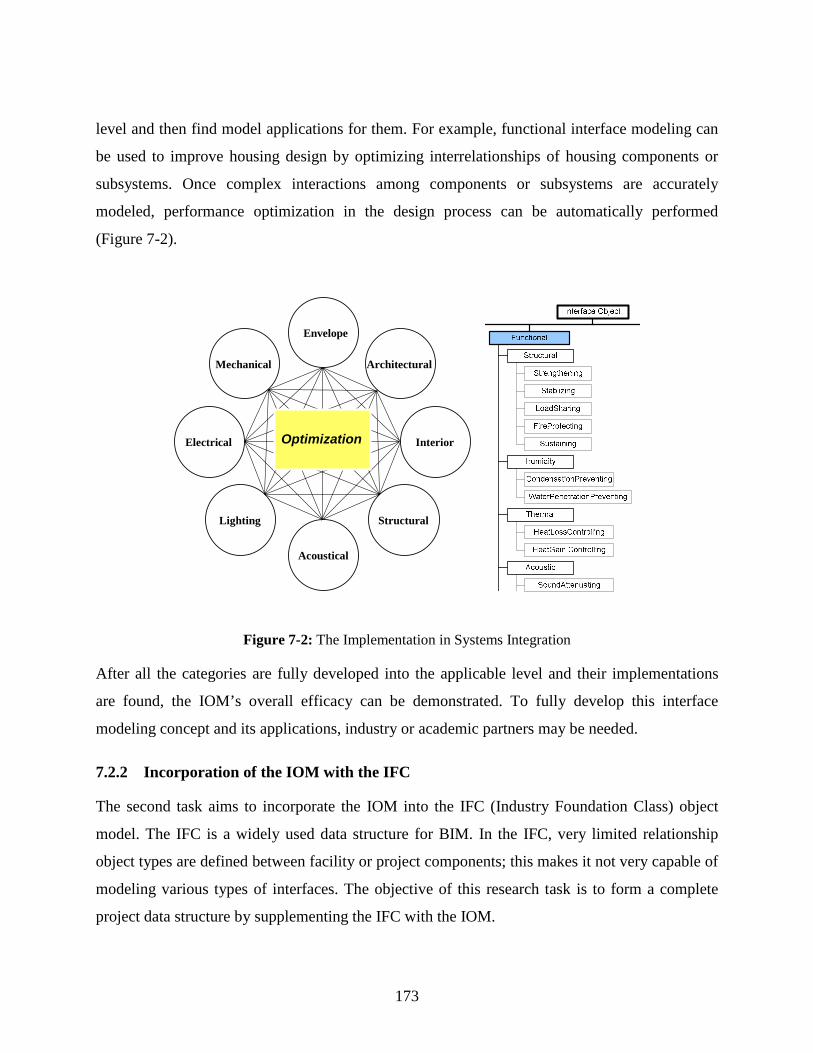
173
level and then find model applications for them. For example, functional interface modeling can
be used to improve housing design by optimizing interrelationships of housing components or
subsystems. Once complex interactions among components or subsystems are accurately
modeled, performance optimization in the design process can be automatically performed
(Figure 7-2).
Figure 7-2: The Implementation in Systems Integration
After all the categories are fully developed into the applicable level and their implementations
are found, the IOM’s overall efficacy can be demonstrated. To fully develop this interface
modeling concept and its applications, industry or academic partners may be needed.
7.2.2 Incorporation of the IOM with the IFC
The second task aims to incorporate the IOM into the IFC (Industry Foundation Class) object
model. The IFC is a widely used data structure for BIM. In the IFC, very limited relationship
object types are defined between facility or project components; this makes it not very capable of
modeling various types of interfaces. The objective of this research task is to form a complete
project data structure by supplementing the IFC with the IOM.
Architectural
Interior
Structural
Acoustical
Lighting
Electrical
Envelope
Mechanical
Optimization

174
Figure 7-3 illustrates the IFC2x3 model architecture. The incorporation may start with
defining the interface resource in the Resource Layer. The interface resource will include all the
defined interface objects for other layers to implement. Then, the Interface Management Domain
may be defined in the Domain Layer. There will also be other adjustments and additions for the
Core and the Interoperability Layers to accommodate the IOM data structure. The complete
incorporation procedures will be proposed in future research.
InterfaceResource
InterfaceManagement
Domain
Figure 7-3: IFC Model Architecture (IAI 2006, with permission from IAI International Council)
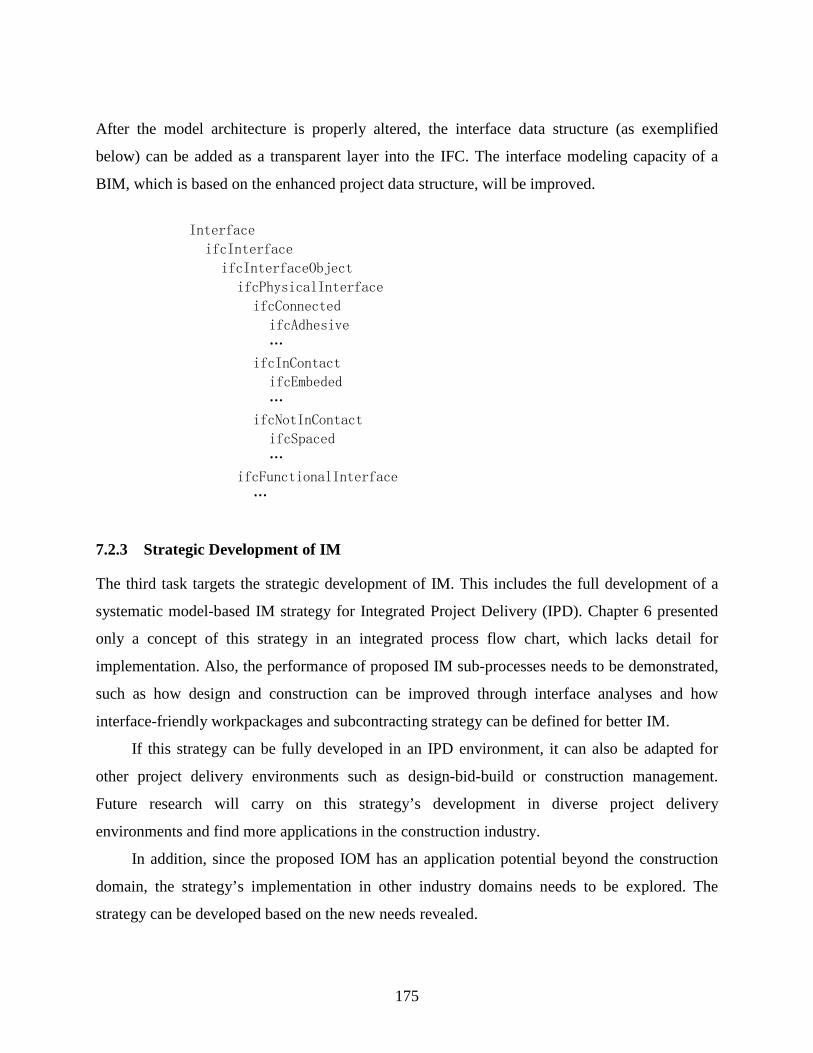
175
After the model architecture is properly altered, the interface data structure (as exemplified
below) can be added as a transparent layer into the IFC. The interface modeling capacity of a
BIM, which is based on the enhanced project data structure, will be improved.
Interface
ifcInterface
ifcInterfaceObject
ifcPhysicalInterface
ifcConnected
ifcAdhesive
…
ifcInContact
ifcEmbeded
…
ifcNotInContact
ifcSpaced
…
ifcFunctionalInterface
…
7.2.3 Strategic Development of IM
The third task targets the strategic development of IM. This includes the full development of a
systematic model-based IM strategy for Integrated Project Delivery (IPD). Chapter 6 presented
only a concept of this strategy in an integrated process flow chart, which lacks detail for
implementation. Also, the performance of proposed IM sub-processes needs to be demonstrated,
such as how design and construction can be improved through interface analyses and how
interface-friendly workpackages and subcontracting strategy can be defined for better IM.
If this strategy can be fully developed in an IPD environment, it can also be adapted for
other project delivery environments such as design-bid-build or construction management.
Future research will carry on this strategy’s development in diverse project delivery
environments and find more applications in the construction industry.
In addition, since the proposed IOM has an application potential beyond the construction
domain, the strategy’s implementation in other industry domains needs to be explored. The
strategy can be developed based on the new needs revealed.
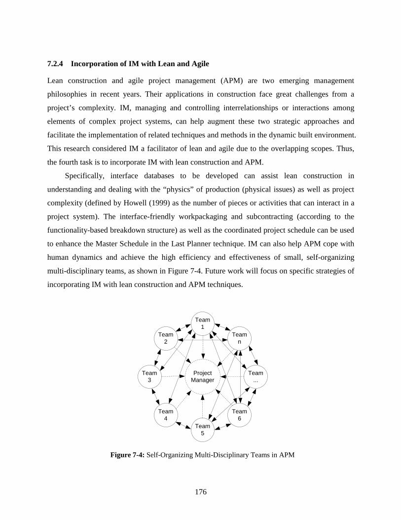
176
7.2.4 Incorporation of IM with Lean and Agile
Lean construction and agile project management (APM) are two emerging management
philosophies in recent years. Their applications in construction face great challenges from a
project’s complexity. IM, managing and controlling interrelationships or interactions among
elements of complex project systems, can help augment these two strategic approaches and
facilitate the implementation of related techniques and methods in the dynamic built environment.
This research considered IM a facilitator of lean and agile due to the overlapping scopes. Thus,
the fourth task is to incorporate IM with lean construction and APM.
Specifically, interface databases to be developed can assist lean construction in
understanding and dealing with the “physics” of production (physical issues) as well as project
complexity (defined by Howell (1999) as the number of pieces or activities that can interact in a
project system). The interface-friendly workpackaging and subcontracting (according to the
functionality-based breakdown structure) as well as the coordinated project schedule can be used
to enhance the Master Schedule in the Last Planner technique. IM can also help APM cope with
human dynamics and achieve the high efficiency and effectiveness of small, self-organizing
multi-disciplinary teams, as shown in Figure 7-4. Future work will focus on specific strategies of
incorporating IM with lean construction and APM techniques.
Team1
Team5
Team4
Team6
Team2
Teamn
Team3
Team...
ProjectManager
Figure 7-4: Self-Organizing Multi-Disciplinary Teams in APM

177
REFERENCE
Alarcón, L.F. and Mardones, D.A. (1998). “Improving the Design-Construction Interface.” Proceedings of the 6th Annual Conference of the International Group for Lean Construction, Guaruja, Brazil. Al-Hammad, A. (1990). “A Study of the Interface Problems between Owners and Contractors over the Construction of Residential Houses in Saudi Arabia.” International Journal for Housing Science and its Applications, IAHS, 14(4), 245-257. Al-Hammad, A. (1993). “Factors Affecting the Relationship between Contractors and Their Sub-contractors in Saudi Arabia.” Building Research and Information, 21(5), 269-273. Al-Hammad, A. (1995). “Interface Problems between Owners and Maintenance Contractors in Saudi Arabia.” Journal of Performance of Constructed Facilities, ASCE, 9(3), 194-205. Al-Hammad, A. (2000). “Common Interface Problems among Various Construction Parties.” Journal of Performance of Constructed Facilities, ASCE, 14(2), 71-74. Al-Hammad, A. and Al-Hammad I. (1996). “Interface Problems between Building Owners and Designers.” Journal of Performance of Constructed Facilities, ASCE, 10(3), 123-126. Al-Hammad, A. and Assaf, S. (1992). “Design-construction interface problems in Saudi Arabia.” Building Research and Information, 20(1), 60-63. Al-Mansouri, O. (1998). The Relationship between the Designer and the Contractor in Saudi Arabia. PhD Thesis, University of Reading, Reading, U.K. Al-Masalha, S.K. (2004). A Common Taxonomy for Modeling Construction Operations. Ph.D. Thesis, Dept. of Building Construction, Virginia Polytechnic Institute and State University. Armacost, R.L., Componation, P.J., Mullens, M.A, and Swart, W.W. (1992). “Customer Requirements in Industrialized Housing.” Proceedings of the 2nd Special Conference on Housing America in the Twenty First Century, ASCE, New York, NY, 48-57. Austin, S., Baldwin, A., Li, B. and Waskett, P. (1999). “Analytical Design Planning Technique for Programming Building Design.” Structures and Buildings: Proceedings of the Institution of Civil Engineers, Thomas Telford Ltd, London, 134(2), 111-118. AutoDesk, Inc. (2002). “The Road to Building Information Modeling.” http://www.laiserin.com/features/bim/autodesk_bim.pdf
178
Ballard, G. and Zabelle, T. (2000). “Project Definition.” White Paper No. 9, Lean Construction Institute. http://www.leanconstruction.org Ballard, G., Koskela, L, Howell, G., and Zabelle, T. (2001). “Production System Design in Construction.” Proceedings of the 9th Annual Conference of the International Group for Lean Construction, Singapore. Bashford, H.H., Sawhney, A., Walsh, K.D., and Kot, Kunal. (2003). “Implication of Even Flow Production Methodology for U.S. Housing Industry.” Journal of Construction Engineering and Management, ASCE, 129(3), 330-337. Bazjanac, V. and Crawley, D.B. (1997). “The Implementation of Industry Foundation Classes in Simulation Tools for the Building Industry.” Proceedings of Building Simulation, Prague, Czech. Bogus, S., Diekmann, J.E., and Molenaar, K.R. (2002). “Methodology to Reconfigure the Design-Construction Interface for Fast-Track Projects.” Computing in Civil Engineering: Proceedings of the International Workshop on Information Technology in Civil Engineering, Washington D.C. Boothroyd, G, Dewhurst, P. and Knight, W. (1994). Product Design for Manufacture and Assembly. Marcel Dekker, New York, NY. Cameron, M.D.O. (1996). “Fast track Management and Control.” Offshore Technology Conference, Annual Proceedings, Richardson, TX, v 2, 247-255. Chan, A.P.C., Ho, D.C.K., and Tam, C.M. (2001). “Design and Build Project Success Factors: Multivariate Analysis.” Journal of Construction Engineering and Management, ASCE, 127(2), 93-100. Chan, A.P.C., Chan, D.W.M., Chiang, Y.H., Tang, B.S., Chan, E.H.W., and Ho, K.S.K. (2004). “Exploring Critical Success Factors for Partnering in Construction Projects.” Journal of Construction Engineering and Management, ASCE, 130(2), 188-198. Chen, Q., Chua, D.K.H., and Song, Y.B. (2003) “Information Flow Integrated Process Modeling.” Proceedings of the 11th Annual Conference of the International Group for Lean Construction, Blacksburg, VA, 519-530. Chen, Q., Wakefield, R.R., and O’Brien, M. (2004). “Lean Applications on Residential Construction Site.” Proceedings of the 2004 Specialty Conference on Leadership and Management in Construction, Hilton Head, SC, 145-157. Chua, D.K.H., Tyagi, A., Ling, S., and Bok, S.H. (2003). “Process-Parameter-Interface Model for Design Management.” Journal of Construction Engineering and Management, ASCE, 129(6), 653-663.

179
Chung, E.K. (1989). A Survey of Process Modeling Tools. Technique Report No. 7, Computer Integrated Construction Research Program, Dept. of Architectural Engineering, Pennsylvania State University. Critsinelis, A. (2001). “The Modern Field Development Approach.” Proceedings of OMAE 2001 20th International Conference on Offshore Mechanics and Artic Engineering, Rio de Janeiro, Brazil. Danso-Amoako, M.O., Issa, R.R.A., and O'Brien, W. (2003). “Framework for a Point-N-Click Interface System for 3D CAD Construction Visualization and Documentation.” Towards a Vision for Information Technology in Civil Engineering: Proceedings of the 4th Joint International Symposium on Technology in Civil Engineering, Nashville, Tennessee. Davis, D. and Standard, C. (1999). “Lean Thinking: Is Thinking Required?” Proceedings of the 1999 Automotive Engineering International, Ann Arbor, MI, 107(7), 98-100. Deming, W.E. (2000). The New Economics for Industry, Government, Education - 2nd Edition. MIT Press, Cambridge, MA. Dove, R. (1995). “Best Agile Practice Reference Base – 1994: Challenge Models and Benchmarks.” 4th Annual Agility Conference, Agility Forum, Bethlehem, PA., March 1995. http://www.parshift.com/publications.htm Eastman C.M. (1999). Building Product Models: Computer Environments Supporting Design and Construction. CRC Press LLC, Boca Raton, FL. Elshennawy, A., Swart, W.W., Mullens, M.A. and Chandra, S. (1991). "A Concurrent Engineering Approach for Industrialized Housing," Proceedings of the 1991 Design Productivity Institute and International Conference, Honolulu, HA. Emerging Construction Technologies. (2000). “4D Modeling.” Division of Construction Engineering and Management, Purdue University. http://www.ecn.purdue.edu/ECT/Other/4d.htm Engelbart, D.C. (1962). “Augmenting Human Intellect: A Conceptual Framework.” Summary Report for SRI Project No. 3578, Stanford Research Institute, Menlo Park, CA. Everett, J.G. (1994). “Ergonomics, Health, and Safety in Construction: Opportunities for Automation and Robotics.” Automation and Robotics in Construction: Proceedings of the 11th International Symposium on Automation and Robotics in Construction, Brighton, U.K., 19-26. Fritschi, N.C. (2002/03). Interface Management for Design Processes: Synergy of Hard and Soft Skills for Project Management. Thesis, Fht Stuttgart-Hochschule Für Technik, WS.

180
Froese, T. (1992). Integrated Computer-Aided Project Management through Standard Object-Oriented Models. Ph.D. Thesis, Stanford University. Gann, D.M. (1996). “Construction as a Manufacturing Process? Similarities and Differences between Industrialized Housing and Car Production in Japan.” Construction Management and Economics, 14, 437-450. Gibb, A.G.F. (1995). “The Management of Construction Interfaces: Preliminary Results from an Industry Sponsored Research Project Concentrating on High Performance Classing in the United Kingdom.” SCAL Convention, Construction Vision 2000. Hagan S. (2005). “To BIM or not to BIM: Owners, Contractors, Engineers and Architects Discuss the Software That Could Change Our Industry.” Hanley-Wood’s New Technology for Construction Executive Forum, Las Vegas, NV. Hammer, M. and Champy, J. (1993). Reengineering the Corporation: A Manifesto for Business Revolution. Haper Business, New York. Hesketh-Prichard, R.M., Brown, N., Twyford, L.R., and Given, M.J. (1998). “Troika Subsea Production Control System.” Offshore Technology Conference, Annual Proceedings, Richardson, TX, v 3, 441-449. Hendrickson, C. and Au. T. (2003). Project Management for Construction: Fundamental Concepts for Owners, Engineers, Architects, and Builders. Version 2.1 for World Wide Web publication. http://www.ce.cmu.edu/pmbook/ Hinze, J. and Andres, T. (1994). “The Contractor-Subcontractor Relationship: the Subcontractor’s View.” Journal of Construction Engineering and Management, ASCE, 120(2), 274-287. Howell, G.A. (1999). “What is Lean Construction—1999.” Proceedings of the 7th Annual Conference of the International Group for Lean Construction, Berkeley, CA. Hsieh, T.-Y. (1998). “Impact of Subcontracting on Site Productivity: Lessons Learned in Taiwan.” Journal of Construction Engineering and Management, ASCE, 124(2), 91-100. IAI (International Alliance for Interoperability). (1999a). Industry Foundation Classes – Release 2.0: An Introduction to the International Alliance for Interoperability and the Industry Foundation Classes. International Alliance for Interoperability, Washington, D.C. IAI (International Alliance for Interoperability). (1999b). Industry Foundation Classes – Release 2.0: IFC Object Model Guide. International Alliance for Interoperability, Washington, D.C.

181
IAI (International Alliance for Interoperability). (2006). IFC/ifcXML Specifications. IAI International Council, International Alliance for Interoperability, Washington, D.C. http://www.iai-international.org/Model/R2x3_final/index.htm INCOSE. (2004). “What is Systems Engineering?” http://www.incose.org/practice/whatissystemseng.aspx INTEC Engineering. (2002). “The Art of Interface Management at INTEC.” INTEC Engineering Quarterly Journal. http://www.intec-hou.com/news/journals/newsletter_spring_02.html INTEC Engineering. (2003). “The Art of Interface Management at INTEC – Part 2.” INTEC Engineering Quarterly Journal. http://www.intec-hou.com/news/journals/newsletter_fall_03.html INTEC Engineering. (2004). “Industry Leaders Cite Interface Management as Critical Area for Improving On-time, On-budget Deliver.” http://www.intec-hou.com/news/pr Johnston, B.A., Beliveau, Y.J., and Wakefield, R.R. (2006). “Icon-based Prototyping for Construction.” Proceedings of the Joint International Conference on Computing and Decision Making in Civil and Building Engineering, Montréal, Canada, 3657-3666. Jonathan Cohen and Associates. (2004). “Object-oriented CAD and Parametric 3D Modeling.” http://www.jcarchitects.com/objectCAD.html Kartam, S., Ballard, G., and Ibbs, C.W. (1994) “Construction Models: A New Integrated Approach.” Proceedings of the 2nd Workshop on Lean Construction, Santiago. Khanzode, A., Fischer, M., and Hamburg, S. (2000). “Effect of Information Standards on the Design-Construction Interface: Case Examples from the Steel Industry.” Computing in Civil and Building Engineering: Proceedings of the 8th International Conference, Stanford, CA. Khemlani, L. (2006). “AIA CBSP Symposium on BIM for Building Envelope Design and Performance.” AECBytes. http://www.aecbytes.com/buildingthefuture/2006/AIA-CBSP_BIM.html Koskela, L. (1992). Application of the New Production Philosophy to Construction. Technical Report No. 72, Center for Integrated Facility Engineering, Dept. of Civil Engineering, Stanford University. Kotelnikov, V. (2004). “Building Effective Cross-Functional Teams.” http://www.1000ventures.com/business_guide/crosscuttings/cross-functional_teams.html Krueger, T. (2002). “Eliminate the Interface.” Journal of Architectural Education, 56(2), 14-17.

182
Kuprenas, J.A. and Rosson, M. (2000). “Interface Consideration on Multiple Prime Contractor Construction Projects.” Construction Congress VI: Building together for a Better Tomorrow in an Increasing Complex World: Proceedings of the Congress, Orlando, FL. Laan, J., Wildenburg, L., and Kleunen, P. (2000). “Dynamic Interface Management in Transport Infrastructure Project.” Proceedings of the 2nd European Systems Engineering Conference, Munich, Germany. Lewendowski, L. (2002). Residential Construction Information Mechanisms and Procedures. Project Report, Dept. of Building Construction, Virginia Polytechnic Institute and State University. Liker, J.K. (2004). The Toyota Way: 14 Management Principles from the World’s Greatest Manufacturer. McGraw-Hill, New York; London. Luiten, G., Froese, T., Björk, B-C., Cooper, G., Junge, R., Karstila, K., and Oxman, R. (1993). “An Information Reference Model for Architecture, Engineering, and Construction.” Proceedings of the 1st International Conference on the Management of Information Technology for Construction, Singapore, 391-406. Luiten, G. (1994). Computer Aided Design for Construction in the Building Industry. PhD Thesis, Faculty of Civil Engineering, Delft University of Technology, The Netherlands. Marghitu, D.D., Dogru, A.H., Johnson, D.B. (1993). “Intelligent CAD Systems: A Requirement Study.” ASME ETCE Conference, Houston, TX, 43, 151-156. Marghitu, D.D., Tanik, M.M., and Dogru, A.H. (1994). “Self-Contained CAD Expert Systems: Future Requirements.” Software Systems Engineering, ASME, 59, 131-135. Marir, F., Aouad, G., and Cooper, G. (1998). “OSCONCAD: A Model-based CAD System Integrated with Computer Applications.” http://www.itcon.org/1998/3/paper.htm Melles, B. (1994). “What Do We Mean by Lean Production in Construction?” Lean Construction, ed. by Alarcon, L., A.A. Balkema, Rotterdam, Netherlands, 1997, 11-16. Miles, R.S. and Ballard, G. (2002). “Problems in the Interfaces between Mechanical Design and Construction: a Research Proposal.” Journal of Construction Research, World Scientific Publishing Company, Singapore, 3(1) 83-95. Mills, S., Erbas, C., Hurmuzlu, Y., and Tanik, M.M. (1992). “Selection of Expert System Development Tools for Engineering Applications.” Transactions of the ASME, 114, 38-45. Mikkola, J.H. (2001). “Modularity and Interface Management: the Case of Schindler Elevators.” Dept. of Industrial Economics and Strategy, Copenhagen Business School, Denmark.

183
Mitchell R. (2006). “Field Report: GM Builds on 3-D Model.” Computerworld, Inc. http://www.computerworld.com/action/article.do?command=viewArticleBasic&articleId=112739 Nakajima, M. (1998). “Knowledge-Based Generation of the Activity Process in Wooden Construction Systems.” Computer-Aided Civil and Infrastructure Engineering, Blackwell Publishing, Oxford, U.K., 13(3), 163-177. Nooteboom, U. (2004). “Interface Management Improves On-time, On-Budget Delivery of Megaprojects.” Journal of Petroleum Technology, Society of Petroleum Engineers, August, 2004. O’Brien, M. and Wakefield, R. (2004). “A Preliminary Method for Evaluating Physical Design Characteristics and Whole House Performance Scoring.” Dept. of Building Construction, Virginia Polytechnic Institute and State University. O’Brien, M., Wakefield, R., and Beliveau, Y. (2000). Industrializing the Residential Construction Site. Technique Report, U.S. Dept. of Housing and Urban Development, Washington, D.C. http://www.huduser.org/publications/manufhsg/ircs.html O’Brien, M., Wakefield, R., and Beliveau, Y. (2002). Industrializing the Residential Construction Site Phase III: Production Systems. Technique Report, U.S. Dept. of Housing and Urban Development, Washington, D.C. http://www.huduser.org/publications/manufhsg/ircs3.html O’Brien, M.J. and Willmott, A.A. (2001). “Planned Inspection and Maintenance.” Proc. Conf. Whole-life Performances of Facades, University of Bath, Bath, U.K. O’Connor, J.T., Rusch, S.E., and Schulz, M.J. (1987). “Constructibility Concepts for Engineering and Procurement.” Journal of Construction Engineering and Management, ASCE, 113(2), 235-248. OMG (Object Management Group). (2005). “Introduction to OMG’s Unified Modeling Language TM (UML).” Object Management Group, Inc. Needham, MA. http://www.omg.org/gettingstarted/what_is_uml.htm Owen, R.L. and Koskela, L. (2006). “An Agile Step Forward in Project Management.” Proceedings of the 2nd Specialty Conference on Leadership and Management in Construction, Grand Bahama Island, Bahamas, 216-224. PATH (Partnership for Advancing Technology in Housing). (2003). PATH Technology Roadmap: Whole House and Building Process Redesign. Technique Report, U.S. Dept. of Housing and Urban Development and Newport Partners L.L.C.
184
Pavitt, T.C. and Gibb, A.G.F. (2003). “Interface Management within Construction: in Particular, Building Façade.” Journal of Construction Engineering and Management, ASCE, 129(1), 8-15. Pavitt, T.C., et al. (2001). “CladdISS – A Strategy for Managing Cladding Interfaces.” ICBEST, International Conference on Building Systems and Technology. Pavitt, T.C. and Gibb, A.G.F. (1999). “Managing Organizational Interfaces in the Cladding Supply Chain: Initial Results from Expert Interview.” Rep., ARCOM, Liverpool, U.K. Post, N.M. (2006). “E-construction as the Norm Is Still 10 to 15 Years Away.” McGraw Hill Construction ENR (Engineering News-Records), McGraw Hill, New York, NY. http://enr.ecnext.com/free-scripts/comsite2.pl?page=enr_document&article=nebuar060220 Prasad, B. (1996). Concurrent Engineering Fundamentals: Integrated Product and Process Organization. Prentice Hall, Upper Saddle River, NJ. Rafiq, M.Y. (2003). “Report on the ASCE Convention and Conference Nashville November 14-18 2003.” Submitted to the Royal Academy of Engineering, School of Civil and Structural Engineering, University of Plymouth. Roy, R., Brown, J., and Gaze, C. (2003). “Re-engineering the Construction Process in the Speculative House-building Sector.” Construction Management and Economics, 21(2), 137-146. Rumbaugh, J., Jacobson, I., and Booch, G. (1999). The Unified Modeling Language Reference Manual, 1st Edition, Addison-Wesley, Boston, MA. Sage, A.P. (1992). Systems Engineering. John Wiley & Sons, Inc., New York, NY. Sanchez, L.M. and Nagi, R. (2001). “A Review of Agile Manufacturing Systems,” International Journal of Production Research, 39(16), 3561-3600. Sanchez, R. (1999). “Modular Architectures in the Marketing Process.” Journal of Marketing, 63 (Special Issue), 92-111. Sanchez, R. (2004). “Creating Modular Platforms for Strategic Flexibility.” Design Management Review, Winter 2004, 58-67. Sawyer, T. (2005a). “3-D Imaging—Maturing Visualization Tools Make Ideas Look Real.” McGraw Hill Construction ENR (Engineering News-Records), McGraw Hill, New York, NY. http://enr.ecnext.com/comsite5/bin/comsite5.pl?page=enr_document&item_id=0271-18891&format_id=XML Sawyer, T. (2005b). “Soaring into the Virtual World—Build It First Digitally.” McGraw Hill Construction ENR (Engineering News-Records), McGraw Hill, New York, NY.
185
http://enr.ecnext.com/coms2/summary_0271-22104_ITM Scherer, R.J. and Katranuschkov, P. (1993). “Architecture of an Object-oriented Product Model Prototype for Integrated Building Design.” Computing in Civil and Building Engineering: Proceedings of the 5th International Conference on Computing in Civil and Building Engineering, ASCE, New York, NY, 393-400. Serén, K.-J., Hannus, M., Karstila, K., Kihlman, M. and Pellosniemi, J. (1993). “Object-oriented CAD Tool Implementations for the Construction Industry.” Espoo: Technical Research Center of Finland. Shrive, C.A. (1992). “Specifying for Multiple Prime Contracts.” The Construction Specifier, March, 1992. Shirley, G.V. (1987). The Management of Manufacturing Flexibility: Studies in the Design/Manufacturing Interface. Ph.D. Thesis, Harvard University. SM Shacker & Associates (2006). “Agile Manufacturing.” http://www.smthacker.co.uk/agile_manufacturing.htm Sorrel, D., Green, J.D., Florida, M.J., and Sheridan, J. (1996). “Liuhua 11-1 Development – Phase I Installation.” Offshore Technology Conference, Annual Proceedings, Richardson, TX, v 4, 349-358. Sozen, Z. (1996). “Management of Transactions: the Design/Construction Interface.” Journal of Architectural and Planning Research, 13(1), 43-49. Stehn, L. and Bergström, M. (2002). “Integrated Design and Production of Multi-storey Timber Frame Houses – Production Effects Caused by Customer-oriented Design.” International Journal of Production Economics, Elsevier, 77, 259-269. Sullivan, J. 1980. Industrialization in the Building Industry. Van Nostrand Reinhold, New York, NY. Sundgren, N. (1999). “Introducing Interface Management in New Product Family Development.” Journal of Product Innovation Management, 16(1), 40-51. Ulrich, K. (1995). “The Role of Product Architecture in the Manufacturing Firm.” Research Policy, 24, 419-440. Ulrich, K. and Eppinger, S.D. (1995). Product Design and Development. McGraw-Hill, New York, NY.
186
UML (Unified Modeling Language). (2005). “OMGTM Resource Page.” Object Management Group, Inc., Needham, MA. http://www.uml.org U.S. Congress, Office of Technology Assessment. (1986). Technology, Trade, and the U.S. Residential Construction Industry-Special Report, OTA-TET-315, U.S. Government Printing Office, Washington, D.C. Wakefield, R., O’Brien, M., and Beliveau, Y. (2001). Industrializing the Residential Construction Site Phase II: Information Mapping. Technique Report, U.S. Dept. of Housing and Urban Development, Washington, D.C. http://www.huduser.org/publications/manufhsg/ircs2.html Wideman, R.M. (2002). “Wideman Comparative Glossary of Project Management Terms v3.1.” http://www.maxwideman.com/pmglossary/PMG_I03.htm Wix, J. and Liebich, T. (1997). “Industry Foundation Classes: Architecture and Development Guidelines.” Information Technology Support for Construction Process Re-Engineering: Proceedings of CIB Workshop W78 and TG10, Cairns, Australia, 419-431. http://itc.scix.net/data/works/att/w78-1997-419.content.pdf
187
VITA Qian Chen was born in Chengdu, China. After graduating from Southwest Jiaotong University in
Architecture in July 1996, she joined the Second Survey and Design Institute of China Railways
as an architect. From July 1998 to August 2002, she had worked with the United Reliance
Engineering Pte Ltd as a project executive and designer in Singapore where she earned a
Master’s degree in Civil Engineering from National University of Singapore in June 2003. In
August 2002, she enrolled in the doctoral program at Virginia Polytechnic Institute and State
University in the Department of Building Construction. Her research interests include interface
management, lean construction, subcontracting, information flow management, and
industrialization of residential construction. She received a second Master’s degree in
Architecture with emphasis on Construction Management in December 2004 and finished her
Ph.D. degree in the summer of 2007. She will work as an assistant professor at the Ohio State
University from September 2007.