an osek os api and memory management for java
TRANSCRIPT
An OSEK Operating System Interfaceand Memory Management for Java
Diploma Thesis
by
Michael Stilkerichborn April 25, 1982, in Forchheim
Department of Computer Science
Distributed Systems and Operating Systems
University of Erlangen-Nuremberg
Tutors: Dipl. Inf. Christian WawersichDipl. Inf. Andreas Gal (UC Irvine, USA)Prof. Dr.-Ing. W. Schroder-PreikschatProf. Michael Franz (UC Irvine, USA)
Begin: April 1, 2006Submission: August 10, 2006

II
Eine OSEK Betriebssystemschnittstelleund Speicherverwaltung fur Java
Diplomarbeit im Fach Informatik
vorgelegt von
Michael Stilkerichgeb. am 25. April 1982 in Forchheim
Angefertigt am
Lehrstuhl fur Informatik 4 (Verteilte Systeme und Betriebssysteme)
Friedrich-Alexander-Universitat Erlangen-Nurnberg
Betreuer: Dipl. Inf. Christian WawersichDipl. Inf. Andreas Gal (UC Irvine, USA)Prof. Dr.-Ing. W. Schroder-PreikschatProf. Michael Franz (UC Irvine, USA)
Beginn der Arbeit: 1. April 2006Abgabe der Arbeit: 10. August 2006

IV

V
Ich versichere, dass ich die Arbeit ohne fremde Hilfe und ohne Benutzung ande-rer als der angegebenen Quellen angefertigt habe, und dass die Arbeit in gleicher oderahnlicher Form noch keiner anderen Prufungsbehorde vorgelegen hat und von dieser alsTeil einer Prufungsleistung angenommen wurde. Alle Ausfuhrungen, die wortlich odersinngemaß ubernommen wurden, sind als solche gekennzeichnet.
Erlangen, den 9. August 2006

VI
Abstract
KESO is a Java runtime environment for embedded systems based on a standard OSEKoperating system. KESO provides a strong isolation of the different applications runningin the system, that is solely based on software.
Software-based memory protection can be advantageous, because hardware withouta memory management unit (MMU) is cheaper to obtain than microcontrollers with anMMU and can provide a higher flexibility for allocating system resources.
The use of the object-oriented programming language Java for developing embeddedsoftware furthermore provides a more robust software development process than thelow-level programming languages C and Assembler, that still dominate the embeddedfield and tend to be error-prone with the ever increasing complexity of software.
In this thesis, a Java abstraction layer for the OSEK operating system interface wasdeveloped, which has the task of providing access to the OSEK system services to Javaapplications, while at the same time restricting access to the system services in order toretain the strong isolation among the different applications.
Furthermore, a Java interface was created, that provides direct access to memory atspecific addresses and therefore access to memory mapped device registers. The mem-ory areas accessible by this means can be restricted to guarantee, that the type-safety ofJava is not violated. This interface allows, amongst other things, the implementation ofdevice drivers in Java.
The main part of this thesis is a heap implementation for KESO that provides auto-matic memory management. The garbage collector assumes a cooperative applicationdeveloper, that incorporates the garbage collector in the design of the whole system andensures, that enough time for the garbage collection will be available.
The developed heap implementation does presently not fulfill hard real-time require-ments, mostly because the fragmentation problem has yet to be solved. The garbagecollector is, however, interruptible at any stage with very low latencies, and does there-fore not affect the real-time capabilities of real-time parts of the system, that do not useautomatic memory management.
The concluding measurements show, that the overhead caused by the measures takento ensure the interruptibility of the garbage collector is tolerable for most applications,and justifiable by the benefits that the application has of automatic memory manage-ment.

VIII

Zusammenfassung
KESO ist eine Java Laufzeitumgebung fur eingebettete Systeme, die auf einem tradi-tionellen OSEK Betriebssystem basiert. KESO ermoglicht eine rein software-basierte,starke Isolierung der verschiedenen im System laufenden Anwendungen.
Ein software-basierter Speicherschutz bietet gegenuber einem auf Hardware basier-ten Speicherschutz die Vorteile, dass zum einen Mikrocontroller ohne Speicherverwal-tungseinheit in der Regel gunstiger in der Anschaffung sind und zum anderen eine fle-xiblere Allokation von Systemressourcen moglich ist.
Die Verwendung der objektorientierten Programmiersprache Java zur Entwicklungvon eingebetteter Software bietet zudem einen robusteren Entwicklungsprozess als diein diesem Feld dominierenden Sprachen C und Assembler, welche in Verbindung mitstandig komplexer werdender Software die Wahrscheinlichkeit von Fehlern in der Pro-grammentwicklung erhohen.
In dieser Arbeit wurde eine Java Abstraktionsschicht fur die Systemschnittstelle desOSEK Systems entwickelt. Diese hat unter anderem die Aufgabe, OSEK Systemdienstefur Java Anwendungen bereitzustellen, aber auch den Zugriff auf diese durch die ver-schiedenen Anwendungen im System zu regeln, so dass die starke Isolation weiterhingewahrleistet bleibt.
Außerdem wurde eine Java Schnittstelle geschaffen, die den direkten Zugriff aufSpeicher an festen Adressen und damit auf in den Speicher abgebildete Gerateregisterermoglicht. Die so zuganglichen Adressbereiche konnen eingeschrankt werden undgewahrleisten so, dass die Typsicherheit von Java nicht verletzt wird. Diese Schnittstelleermoglicht unter anderem die Entwicklung von Geratetreiber in Java.
Den Hauptteil dieser Arbeit stellt eine Heap Implementierung fur KESO mit auto-matischer Speicherverwaltung dar. Die Speicherbereinigung geht von einem kooperati-ven Anwendungsentwickler aus, der sie in den Zeitplan des Gesamtsystems einplant undgewahrleistet, dass ausreichend Zeit fur die Speicherbereinigung zur Verfugung steht.
Vor allem aufgrund der noch ungelosten Fragmentierungsproblematik kann die ent-wickelte Heap Implementierung derzeit allerdings noch keine harten Echtzeitanforde-rungen erfullen. Der Speicherbereinigungsmechanismus ist jedoch mit geringer Latenzan jeder Stelle unterbrechbar und beeintrachtigt somit nicht die Echtzeitfahigkeit ande-rer Teile des Systems, die auf eine automatische Speicherbereinigung verzichten.
Die abschließenden Messungen zeigen, dass der Mehraufwand, der durch die zurUnterbrechbarkeit der Speicherbereinigung notwendigen Maßnahmen entsteht, fur diemeisten Anwendungen tolerierbar ist, und durch die Vorteile, die den Anwendungendurch die automatische Speicherbereinigung entstehen, gerechtfertigt wird.

X

Contents
1 Introduction 11.1 Motivation . . . . . . . . . . . . . . . . . . . . . . . . . . . . . . . . . 1
1.1.1 Problems Imposed by Heterogeneity in the Embedded Field . . 11.1.2 Solving Integration Problems by Reducing Diversity . . . . . . 11.1.3 Software Isolation in the Area of Personal Computing . . . . . 21.1.4 Migration of Operating System Concepts . . . . . . . . . . . . 3
1.2 Typographic Conventions . . . . . . . . . . . . . . . . . . . . . . . . . 4
2 Related Work 72.1 The AJACS Project . . . . . . . . . . . . . . . . . . . . . . . . . . . . 72.2 The JX Java Operating System . . . . . . . . . . . . . . . . . . . . . . 72.3 Embedded JVMs . . . . . . . . . . . . . . . . . . . . . . . . . . . . . 8
2.3.1 NanoVM . . . . . . . . . . . . . . . . . . . . . . . . . . . . . 82.3.2 TinyVM . . . . . . . . . . . . . . . . . . . . . . . . . . . . . . 82.3.3 The Squawk Virtual Machine . . . . . . . . . . . . . . . . . . 8
2.4 Java and Real-Time . . . . . . . . . . . . . . . . . . . . . . . . . . . . 92.4.1 The Real-Time Specification for Java . . . . . . . . . . . . . . 92.4.2 JamaicaVM . . . . . . . . . . . . . . . . . . . . . . . . . . . . 9
3 Architecture of the KESO System 113.1 Conceptional Architecture . . . . . . . . . . . . . . . . . . . . . . . . 113.2 Code Generation Concept . . . . . . . . . . . . . . . . . . . . . . . . . 13
4 KESO Runtime Data Structures 174.1 Class Store . . . . . . . . . . . . . . . . . . . . . . . . . . . . . . . . 174.2 Domain Descriptor Table and Domain Identifiers . . . . . . . . . . . . 184.3 Object Layout . . . . . . . . . . . . . . . . . . . . . . . . . . . . . . . 19
4.3.1 Object Header . . . . . . . . . . . . . . . . . . . . . . . . . . 194.3.2 Array Classes . . . . . . . . . . . . . . . . . . . . . . . . . . . 204.3.3 Non-Array Classes . . . . . . . . . . . . . . . . . . . . . . . . 20
XI
XII CONTENTS
5 OSEK Abstraction Layer 235.1 Conceptual Design . . . . . . . . . . . . . . . . . . . . . . . . . . . . 24
5.1.1 Magic Methods . . . . . . . . . . . . . . . . . . . . . . . . . . 245.1.2 Access Restrictions to OSEK Services . . . . . . . . . . . . . . 245.1.3 Provision of OSEK Constants and Identifiers . . . . . . . . . . 25
5.2 Object Abstractions and Name Service . . . . . . . . . . . . . . . . . . 265.2.1 General Description . . . . . . . . . . . . . . . . . . . . . . . 275.2.2 Explanation of the Example . . . . . . . . . . . . . . . . . . . 275.2.3 Java Interface to the Name Service . . . . . . . . . . . . . . . . 285.2.4 Related Issues . . . . . . . . . . . . . . . . . . . . . . . . . . . 29
5.3 Task Management . . . . . . . . . . . . . . . . . . . . . . . . . . . . . 295.3.1 Implementation of Portals . . . . . . . . . . . . . . . . . . . . 305.3.2 Task-Related System Services . . . . . . . . . . . . . . . . . . 335.3.3 Wrapper Functions . . . . . . . . . . . . . . . . . . . . . . . . 345.3.4 Issues of the Object Abstraction . . . . . . . . . . . . . . . . . 35
5.4 Interrupt Handling . . . . . . . . . . . . . . . . . . . . . . . . . . . . 355.5 Event Mechanism . . . . . . . . . . . . . . . . . . . . . . . . . . . . . 365.6 Resource Management . . . . . . . . . . . . . . . . . . . . . . . . . . 375.7 Alarms and Counters . . . . . . . . . . . . . . . . . . . . . . . . . . . 38
5.7.1 Counters . . . . . . . . . . . . . . . . . . . . . . . . . . . . . 385.7.2 Alarms . . . . . . . . . . . . . . . . . . . . . . . . . . . . . . 38
5.8 Problems Imposed by Portals . . . . . . . . . . . . . . . . . . . . . . . 40
6 Memory Management 416.1 Data Structures of the IdleRoundRobin Heap . . . . . . . . . . . . . . 42
6.1.1 Slot Division and Bitmap . . . . . . . . . . . . . . . . . . . . . 426.1.2 Free Memory List . . . . . . . . . . . . . . . . . . . . . . . . 446.1.3 Working Stack for the GC Scanning Phase . . . . . . . . . . . 456.1.4 Managed Domains Array . . . . . . . . . . . . . . . . . . . . . 456.1.5 Garbage Collector Domain . . . . . . . . . . . . . . . . . . . . 45
6.2 Coloring of Objects . . . . . . . . . . . . . . . . . . . . . . . . . . . . 466.3 Interrupt Friendly List Implementation . . . . . . . . . . . . . . . . . . 46
6.3.1 Interface to the Caller . . . . . . . . . . . . . . . . . . . . . . . 476.3.2 Interface to the Callback Function . . . . . . . . . . . . . . . . 476.3.3 Synchronization of Recursive Invocations . . . . . . . . . . . . 49
6.4 Allocator Function . . . . . . . . . . . . . . . . . . . . . . . . . . . . 516.4.1 Generic Allocator Function Interface . . . . . . . . . . . . . . 516.4.2 IdleRoundRobin Allocator Function . . . . . . . . . . . . . . . 526.4.3 Allocation of a Memory Block . . . . . . . . . . . . . . . . . . 52
6.5 The Garbage Collector of the IRR Heap . . . . . . . . . . . . . . . . . 556.6 Phases of the IRR Garbage Collector . . . . . . . . . . . . . . . . . . . 55
CONTENTS XIII
6.6.1 Domain Selection . . . . . . . . . . . . . . . . . . . . . . . . . 576.6.2 Marking of Free Memory Blocks . . . . . . . . . . . . . . . . 586.6.3 Scan and Mark of Reachable Objects . . . . . . . . . . . . . . 596.6.4 Sweep: Recover Memory of Unreachable Objects . . . . . . . . 62
6.7 Interruptibility of the Scan Phase . . . . . . . . . . . . . . . . . . . . . 666.7.1 Write Barriers . . . . . . . . . . . . . . . . . . . . . . . . . . . 676.7.2 Atomic Scanning of the Task Stacks . . . . . . . . . . . . . . . 676.7.3 Scan Order . . . . . . . . . . . . . . . . . . . . . . . . . . . . 70
6.8 Benchmarks . . . . . . . . . . . . . . . . . . . . . . . . . . . . . . . . 706.8.1 Overhead Measurements . . . . . . . . . . . . . . . . . . . . . 716.8.2 Benefits of the Coloring Optimization . . . . . . . . . . . . . . 736.8.3 Differences between inlined and not-inlined Write barriers . . . 746.8.4 Runtime Spectrum of the pushObject() Function . . . . . . 75
7 Conclusion and Future Work 777.1 OSEK Abstraction Layer . . . . . . . . . . . . . . . . . . . . . . . . . 777.2 IdleRoundRobin Heap Implementation . . . . . . . . . . . . . . . . . . 787.3 KESO Future Development . . . . . . . . . . . . . . . . . . . . . . . . 79
Bibliography 81
List of Figures 85

XIV CONTENTS
Chapter 1
Introduction
1.1 Motivation
1.1.1 Problems Imposed by Heterogeneity in the Embedded FieldWhile the development speed in the field of universal computers is abating, the embed-ded computing industry is booming. There is a vast number of visions in this field andpromising concepts like the idea of pervasive computing are still in their infancy. Anend of this fast-paced development is not in sight.
The automotive industry constitutes one major application area of embedded com-puting. Modern cars may contain up to well over 100 microcontrollers for all kinds oftasks, ranging from convenience functions, such as the automatic regulation of the airconditioning to maintain a set temperature, over infotainment components, e.g. a carnavigation system, to safety-critical functions, like controlling the braking system ofthe car.
More often than not, the multitude of microcontrollers in a car as well as the soft-ware running on these controllers are produced by a number of different manufacturers.The resulting heterogeneity in the deployed hardware and software imposes integrationproblems.
1.1.2 Solving Integration Problems by Reducing DiversityWith microcontrollers becoming more and more powerful, the heterogeneity of the hard-ware can be reduced by integrating multiple tasks on a single, more powerful microcon-troller.
This approach introduces new problems though. When deploying dedicated micro-controllers, physical separation provides isolation of the tasks running on these con-trollers. An erroneous task running on a dedicated controller cannot spread and impacttasks running on other microcontrollers. When multiple tasks share a microcontroller,
1
2 CHAPTER 1. INTRODUCTION
the physical isolation ceases. Usually, there are no memory protection mechanisms pre-venting one task from accessing or modifying another task’s memory. Thus, a malfunc-tioning task can affect the other tasks on the controller and possibly cause a malfunctionof the whole system.
Because the software integrated on a microcontroller is often developed by differ-ent manufacturers, this problem can hardly be regulated by means of a diligent qualityassurance. In case of the failure of a component in the car, the microcontroller, thatwas controlling the component that failed, is easy to determine, but the software task,that was the cause for the failure, and that may be a different task than the one thatwas controlling the failed component, can hardly be identified. In case of claims fordamages, however, it is necessary to determine the manufacturer of the malfunctioningcomponent, which would require a complex and costly reconstruction of the failure.
The problem is even aggravated by the way most embedded software is developed.The dominating programming languages in the embedded field are C and Assembler,with which development tends to be error-prone, because they provide few concepts forsupporting robust code development. Increasing functionality of software is accompa-nied by increasing code size and complexity, both factors that also raise the chance offaulty software development.
1.1.3 Software Isolation in the Area of Personal ComputingThough these problems are new to the embedded field, they are well-known from thefield of personal computers and mature concepts for solving these problems have alreadybeen developed.
Object-oriented programming (OOP) languages such as C++ and Java allow devel-oping applications in a more maintainable and less error-prone manner.
Encapsulation is one of the core concepts carried out by OOP, that restricts accessto data to a well-defined set of established channels. Though this concept reduces theerror-proneness of application development and is encouraged by OOP, it is commonlynot enforced by object-oriented programming languages.
The Java platform goes one step farther by running software in a controlled envi-ronment isolated from the rest of the system, the Java Virtual Machine (JVM) [LY99].Java achieves software-based memory protection without a memory management unit(MMU) through its strict type system, that inhibits the use of arbitrary values as ad-dresses. Type-safety is, in the last instance, ensured by the Java bytecode verifier, butalso at compile time by a trustworthy Java compiler.
The memory protection provided by the Java platform, however, is still not sufficientto solve the isolation problem. Running multiple tasks, or threads in terms of Java, in asingle JVM still possibly allows one task to gain access to the memory of another taskthrough static class fields, that can be used by all tasks running in the JVM simulta-neously. Furthermore, there is no means of task specific resource allocation, which is
1.1. MOTIVATION 3
Heap
DomainZero (Microkernel)
Domain A
StacksJava−
ThreadsTCBs
Portal
Portal
Domain B
Portal
Portal
Domain C
Portal
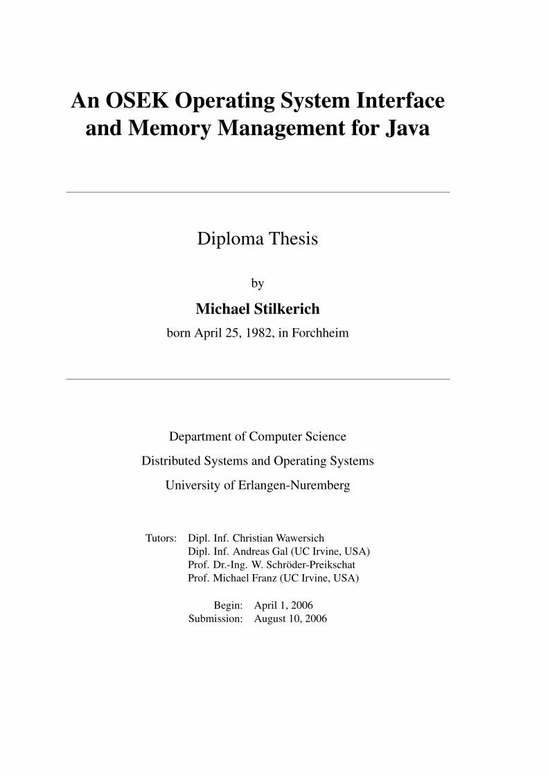
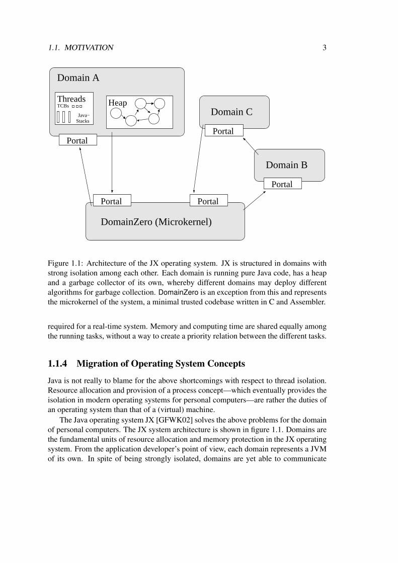
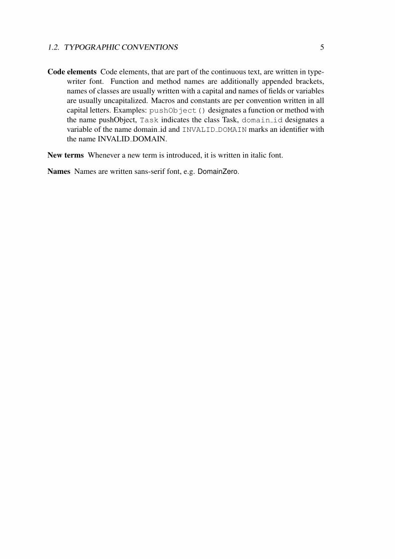
Figure 1.1: Architecture of the JX operating system. JX is structured in domains withstrong isolation among each other. Each domain is running pure Java code, has a heapand a garbage collector of its own, whereby different domains may deploy differentalgorithms for garbage collection. DomainZero is an exception from this and representsthe microkernel of the system, a minimal trusted codebase written in C and Assembler.
required for a real-time system. Memory and computing time are shared equally amongthe running tasks, without a way to create a priority relation between the different tasks.
1.1.4 Migration of Operating System Concepts
Java is not really to blame for the above shortcomings with respect to thread isolation.Resource allocation and provision of a process concept—which eventually provides theisolation in modern operating systems for personal computers—are rather the duties ofan operating system than that of a (virtual) machine.
The Java operating system JX [GFWK02] solves the above problems for the domainof personal computers. The JX system architecture is shown in figure 1.1. Domains arethe fundamental units of resource allocation and memory protection in the JX operatingsystem. From the application developer’s point of view, each domain represents a JVMof its own. In spite of being strongly isolated, domains are yet able to communicate

4 CHAPTER 1. INTRODUCTION
and cooperate via the portal mechanism, that allows domains to offer service methodsto other domains and can be used in a manner similar to Java RMI (Remote MethodInvocation) [Mic97]. Whenever an object is parameter to a service method invocationat a portal, a copy of the object along with its transitive closure is created in the servicedomain and used in the execution. Thus, a reference to an object of a domain’s heapnever crosses a domain boundary.
An attempt [Dom04] to port JX to the Lego Mindstorm RCX architecture has shown,that JX in its current form is not suitable for being deployed on microcontrollers. TheJX microkernel alone has a size of 70–100 kB, which is small in the area of personalcomputers, but too big for embedded microcontrollers. This is due to features, that aredesirable and required in a Java operating system for personal computers, such as thedynamic loading of classes. Embedded systems in contrast are statically configured. Afacility such as a dynamic class loader is not required, because all classes ever used areknown at system creation time.
Inspired by JX concepts, KESO, a Java runtime environment specially suited for em-bedded environments, built on top of a standard operating system for microcontrollers,has been developed. An OSEK [OSE05] operating system was chosen as the underlyingoperating system, because of its widespread use in the automotive industry.
In this thesis, a Java abstraction layer for the underlying OSEK operating systemwas developed, that provides a controlled way for Java applications to access the OSEKsystem services. Furthermore, a heap implementation that provides automatic memorymanagement was developed.
This thesis is structured as follows: In chapter 2, other work related to KESO isreviewed. In chapter 3 and chapter 4, the architecture and some relevant runtime datastructures of KESO are explained to establish the KESO-related knowledge required forthe remainder of this work. The design and implementation of the OSEK abstractionlayer is covered in chapter 5, and chapter 6 describes the heap implementation that wasdeveloped in this work. Finally, chapter 7 summarizes the results and outstanding issuesof the developed KESO components, and gives a glimpse of the current and future workon the KESO system.
1.2 Typographic Conventions
Throughout this thesis, the following typographic conventions are used:
OSEK concepts and task states OSEK concepts and task states are written with cap-itals to differentiate from common language use. The affected terms describingOSEK concepts are Tasks, Resources, Events, Alarms and Counters. The existingOSEK task states are Ready, Suspended, Waiting and Running.
1.2. TYPOGRAPHIC CONVENTIONS 5
Code elements Code elements, that are part of the continuous text, are written in type-writer font. Function and method names are additionally appended brackets,names of classes are usually written with a capital and names of fields or variablesare usually uncapitalized. Macros and constants are per convention written in allcapital letters. Examples: pushObject() designates a function or method withthe name pushObject, Task indicates the class Task, domain id designates avariable of the name domain id and INVALID DOMAIN marks an identifier withthe name INVALID DOMAIN.
New terms Whenever a new term is introduced, it is written in italic font.
Names Names are written sans-serif font, e.g. DomainZero.

6 CHAPTER 1. INTRODUCTION
Chapter 2
Related Work
2.1 The AJACS Project
The AJACS (Applying Java to Automotive Control Systems) project [con02] did gen-eral research on deploying Java in automotive control systems, i.e. on static embeddedsystems, and therefore has the same target platforms as the KESO system.
The main objective was developing and defining an open technology that is basedon existing standards of the automotive industry, explicitly naming OSEK/VDX oper-ating systems. The expected benefits of using Java on automotive control systems wererestricted to a single JVM approach, particularly to software structuring, reusability,dependability, portability and robustness benefits.
The AJACS project concluded with numerous recommendations on how to deal withthe limitations of various aspects of Java with respect to real-time support.
While KESO also targets all of the benefits expected from the sole use of Java forthe development of embedded applications, it mainly differs from AJACS in the multiJVM approach, that puts the main focus on the isolation of the tasks integrated on thecontroller.
2.2 The JX Java Operating System
The multi JVM architecture of the Java operating JX [GFWK02] posed the paradigmfor the architecture of the KESO system. While the architecture of KESO is similar tothe architecture of JX, both systems have not much in common in their implementation,which is mainly a consequence of the diversities of the application domains that bothsystems target, which are personal computers for the JX operating system and micro-controllers for the KESO system, and the concepts inherited by the underlying OSEKoperating system for the KESO system, while JX uses its own microkernel.
7
8 CHAPTER 2. RELATED WORK
2.3 Embedded JVMs
This section reviews some embedded JVMs, that are related to KESO in that they alsohave to face resource limitations of the target hardware.
2.3.1 NanoVM
NanoVM [Har06] is a small embedded JVM for the AVR architecture. It is limited toa small subset of the Java class library and the Java programming language. NanoVMinterprets Java bytecode at runtime, but requires standard class files to be converted to aNanoVM specific format before uploading the classes to the target.
2.3.2 TinyVM
TinyVM [Sol00] is a Java-based firmware replacement for the Lego MindstormTM RCXmicrocontroller with a footprint of about 10 kB. Similar to NanoVM, TinyVM does notprovide a complete Java runtime environment, notably garbage collection and floatingpoint support are missing in TinyVM.
2.3.3 The Squawk Virtual Machine
The Squawk VM [SCC+06] is a small JVM written in Java that runs without an operat-ing system. Squawk complies to the Connected Limited Device Configuration (CLDC)1.1 Java Micro Edition (Java ME) configuration [Sun04]. Java bytecode is convertedto a Squawk specific Suite File format, that incorporates space, execution and garbagecollection simplification optimizations.
Squawk implements an isolation mechanism similar to that of Java SpecificationRequest (JSR) 121 [Cza00, jsr06]. Squawk encapsulates applications into so-calledIsolates, whereby each Isolate maintains an own copy of mutable data such as staticclass variables. An Isolate may contain multiple threads, therefore the Isolate conceptshows some similarities to the domain concept used in KESO. Contrary to domains, allIsolates allocate new objects from the same heap, therefore Isolates are no separate unitsof memory allocation.
Squawk further differs from KESO in the thread and scheduling concept, and thenon-preemptible system code including the garbage collector, that can have a negativeimpact on the interrupt handling latency.
2.4. JAVA AND REAL-TIME 9
2.4 Java and Real-Time
2.4.1 The Real-Time Specification for JavaThe real-time specification for Java (RTSJ) [BBG+00] is an extension to the Java lan-guage definition and the Java standard libraries, that adds support for real-time threads,while remaining backwards compatible with existing (non real-time) Java applications.Among the important changes are the necessity of a priority inheritance or a priorityceiling mechanism on Java monitors and an extended thread concept. Two types ofreal-time threads are introduced, that can be assigned priorities higher than the priorityof the garbage collector. The system is then split in a real-time part and a non real-timepart, where the real-time threads use memory areas that are not under the control of thegarbage collector. The communication and synchronization between real-time and nonreal-time parts is heavily restricted to avoid the deferment of real-time threads by thegarbage collector, that can occur by synchronizing a non real-time thread and a real-timethread in combination with priority ceiling or priority inheritance.
2.4.2 JamaicaVMThe commercial JVM JamaicaVM [Sie04] provides support for the RTSJ and contains agarbage collector, that is suitable for hard real-time constraints. The heap of JamaicaVMis divided in fixed-size blocks, that also represent the increment unit of the preemptiblegarbage collector. Garbage collection is scheduled upon allocation by the allocatingthread. The amount of work done by the thread depends on the size of the allocatedobject, i.e. threads have to pay for the allocation by performing garbage collector work.The fragmentation problem is solved by composing objects of a linked list of fixed sizeblocks. These blocks do not need to be sequential on the heap, thus completely avoidingthe need to compact memory.

10 CHAPTER 2. RELATED WORK
Chapter 3
Architecture of the KESO System
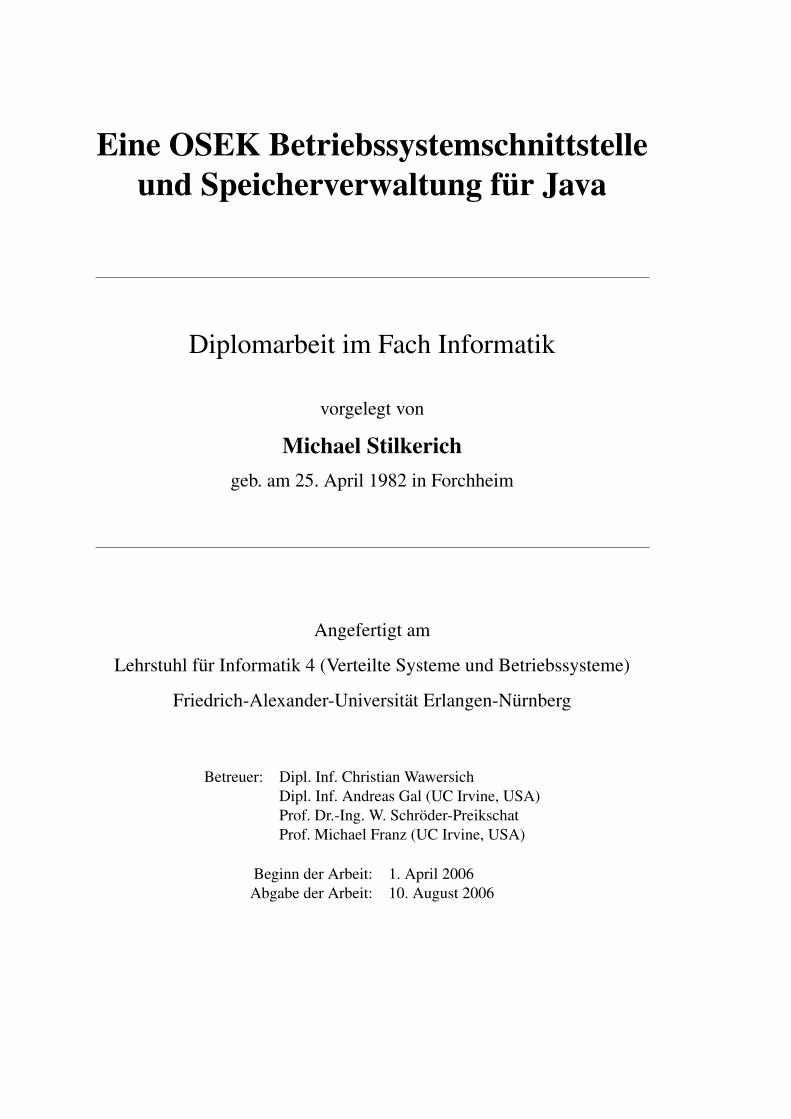
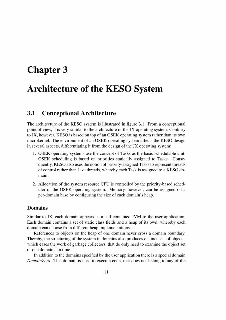
3.1 Conceptional ArchitectureThe architecture of the KESO system is illustrated in figure 3.1. From a conceptionalpoint of view, it is very similar to the architecture of the JX operating system. Contraryto JX, however, KESO is based on top of an OSEK operating system rather than its ownmicrokernel. The environment of an OSEK operating system affects the KESO designin several aspects, differentiating it from the design of the JX operating system:
1. OSEK operating systems use the concept of Tasks as the basic schedulable unit.OSEK scheduling is based on priorities statically assigned to Tasks. Conse-quently, KESO also uses the notion of priority-assigned Tasks to represent threadsof control rather than Java threads, whereby each Task is assigned to a KESO do-main.
2. Allocation of the system resource CPU is controlled by the priority-based sched-uler of the OSEK operating system. Memory, however, can be assigned on aper-domain base by configuring the size of each domain’s heap.
DomainsSimilar to JX, each domain appears as a self-contained JVM to the user application.Each domain contains a set of static class fields and a heap of its own, whereby eachdomain can choose from different heap implementations.
References to objects on the heap of one domain never cross a domain boundary.Thereby, the structuring of the system in domains also produces distinct sets of objects,which eases the work of garbage collectors, that do only need to examine the object setof one domain at a time.
In addition to the domains specified by the user application there is a special domainDomainZero. This domain is used to execute code, that does not belong to any of the
11
12 CHAPTER 3. ARCHITECTURE OF THE KESO SYSTEM
OSEK
Microcontroller
5 2
Portal
Portal
Device−MemoryOSEK Services
KESO Services
KESO Runtime Environment
Domain A
Heap/GC
Tasks
Resources
Alarms
ISRs
Domain C
Domain B
Figure 3.1: KESO Conceptional Architecture
regular domains, which can, for instance, be the case for interrupt service routines.Furthermore, it contains system objects that are accessible from all other domains, i.e.globally visible immortal system objects1. DomainZero does not contain any Tasks.
DomainZero also exists in JX, but the semantics is entirely different. It is planned,that DomainZero will be removed from KESO and replaced by a user configurable sys-tem domain, that is only optionally present in the system in case global code or objectsare required by the user application.
Portals
Inter-domain communication is possible via portals in a manner similar to JX. A servicedomain can provide a portal service, that allows Tasks of other domains to execute codein the service domain. A portal service consists of a well-defined interface that offersservice methods to other domains. Tasks of other domains may invoke methods of theportal. The execution of a service method takes place in the environment of the servicedomain.
The implementation of KESO portals is described as part of the Task Managementin section 5.3.1.
1A reference to a global system object can be present in multiple domains. However, these objects arenot allocated from a domain heap and not subject to garbage collection, therefore this does not pose anyproblems. System objects are discussed more detailed in chapter 5.
3.2. CODE GENERATION CONCEPT 13
KESO Runtime EnvironmentThe two major functions of the KESO runtime environment layer are the provision ofa Java runtime environment for the Java applications and a Java class library providingaccess to KESO services.
KESO services can be divided in three classes:
• Provision of OSEK services on the Java level
• Device-Memory
• Device drivers
The first class allows the user applications to use the system services of the underly-ing OSEK operating system on the Java level. These services include synchronizationand notification mechanisms as well as limited access to the hardware, e.g. throughservices, that allow to disable and enable interrupts. The KESO services of this classare part of the OSEK abstraction layer (chapter 5).
Further hardware accesses to memory mapped device registers are possible throughDevice-Memory, that is also a part of the JX operating system.
Device-Memory provides methods to access a specific region of memory with meth-ods similar to raw access. The memory region accessible via Device-Memory can belimited to prevent a breakout from the Java protection mechanisms, e.g. by modifyingthe heap of a domain or the stack of Tasks. Device-Memory allows, amongst otherthings, the implementation of device drivers in Java.
Device Drivers are not available yet, but a CAN (Controller Area Network) driverfor the Tricore architecture is currently in development. Device drivers will allow ac-cess to hardware devices on the Java level without the need to program those devices.Applications can then use the higher level interface provided by a device driver, whichgreatly increases the portability of user applications.
3.2 Code Generation ConceptThe user applications are developed in Java and available as Java bytecode after havingbeen processed by a Java compiler. Interpreting or even compiling the bytecode to nativecode at runtime on the target microcontroller is not feasible, because memory and CPUpower are very limited on the target platforms. Instead, the bytecode is compiled to Csource code ahead of time by the KESO builder. Creating C source code rather thandirectly compiling the bytecode to native code has a few advantages:
• Directly compiling to native code would require a compiler back-end for theKESO builder for each supported target platform. However, a standard C com-piler is available for almost all of the target platforms.

14 CHAPTER 3. ARCHITECTURE OF THE KESO SYSTEM
• The available C compilers allow to create highly optimized code at the functionlevel.
• C source code is easier to read than native code, which eases debugging.
• A separate compiler back-end for each target platform increases the complexityof the KESO builder and increases the probability of software bugs.
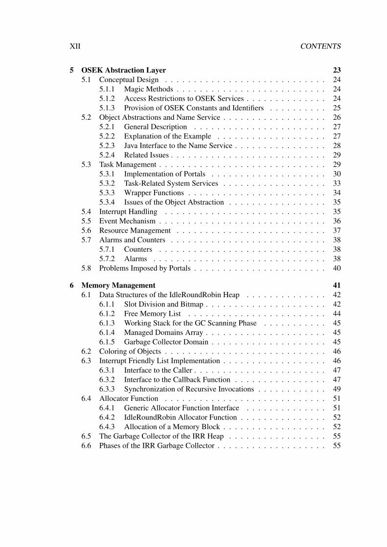
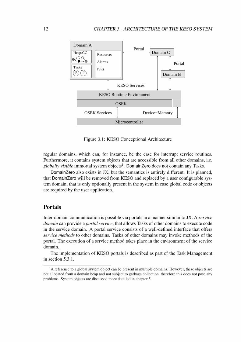
Components and ProcessesThe generation process of a KESO system is illustrated in figure 3.2. The componentsthat participate in the process are of three kinds:
• Components provided by the developers of the user application. These are com-prised by the Java source code of the user application and the KESO system con-figuration file.
• Standard components, that are comprised by a Java compiler, that compiles Javasource code to Java bytecode, the OSEK system generator (OSEK SG), that cre-ates the source code of the OSEK kernel from the OSEK OIL [OSE04] (OSEKimplementation language) configuration file, and a C compiler and linker, that isused to compile the C sources of the user application and the OSEK kernel, andlinks the resulting objects files to the KESO binary image.
• KESO components, comprised by the KESO class library, that provides the KESOservices to Java applications, the KESO autoclass generator, which automaticallygenerates parts of the KESO class library from the system configuration file, e.g.for providing OSEK identifiers on the Java level, and the KESO builder, thatcompiles the Java bytecode of the user application to C source code and generatesthe OSEK OIL configuration file from the KESO system configuration file.
The generated C code does not only contain the compiled class files, but also the KESOruntime data structures (chapter 4), that include data structures such as the class store,that contains type information required at runtime for tasks such as checking a cast,and the virtual method table, that is required to resolve virtual methods calls at runtime.Moreover, additional code is inserted to retain the properties of a JVM, such as nullreference checks and array boundary checks, and the code of other services of the KESOruntime layer, such as the garbage collector and the portal services.
Optimizations with Respect to Code SizeKESO is a static system, that does not allow the dynamic loading of classes at runtime,which opens some optimization potential for reducing the size of the generated system.
3.2. CODE GENERATION CONCEPT 15
Standard Java Compiler
OSEK SG
KESO SystemConfiguration
Standard C−Compiler
ApplicationJava Sources
KESO
Application
Standard
Components
libraryKESO class
Java Bytecode
KESO Builder (Bytecode−2−C)
OSEK Kernel Source
KESO Binary Image
OIL ConfigurationKESO C−Source
KESO AutoclassGenerator
Figure 3.2: KESO System Generation Process
The KESO compiler performs a reachability analysis on the bytecode and eliminatesclasses, methods and fields, that are not accessed by the user application. This reducesboth, the code size of the generated system and the size of the KESO data structures.Additionally, only the parts of the KESO abstraction layer, that are actually used by theapplication, are added to the generated code, e.g. if an application does not make use ofOSEK Resources, the data structures and code for the Resource-related services are notadded to the generated system.
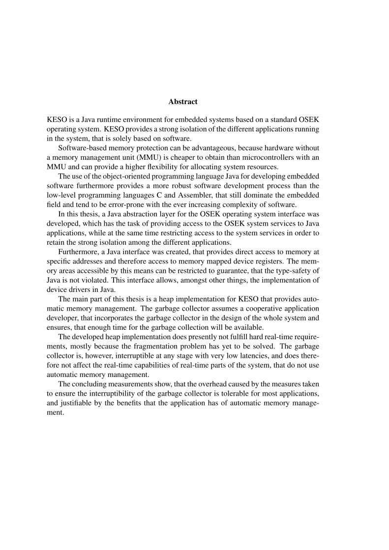
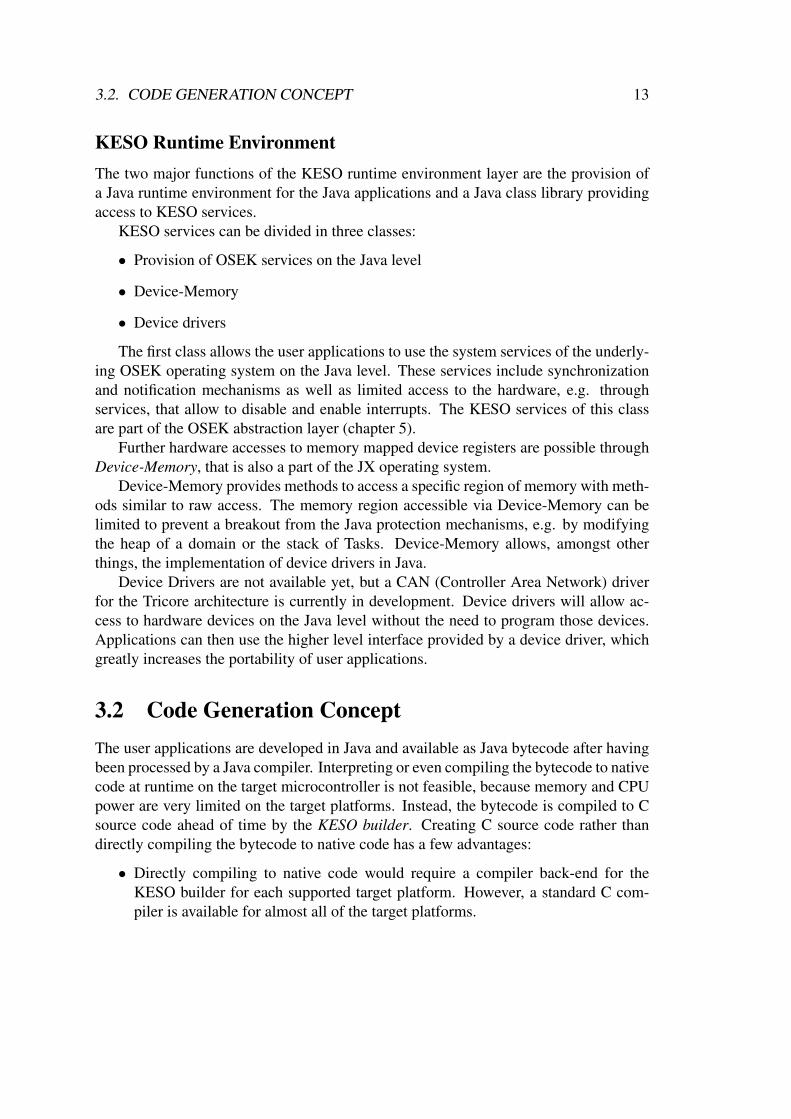
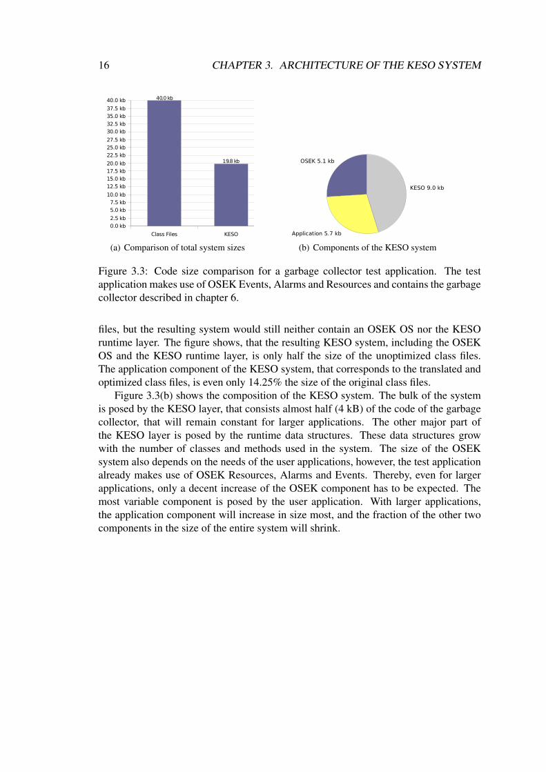
Figure 3.3 shows a code size comparison for a test application, that was used totest the garbage collector discussed in chapter 6. The test application processes an in-finite loop and maintains a FIFO of fixed size. In each loop cycle, a new element is beallocated and added to the FIFO, and another element is removed. Additionally, the ap-plication outputs a string, that is constructed using numerous StringBuffer objectsfrom several integers and constant strings. At the end of a cycle, the Task waits for anOSEK Event, triggered by a cyclic OSEK Alarm, and continue with the execution oncethe Event has been set. In the meantime, the garbage collector reclaims the memory ofunreachable objects. OSEK Resources are also used to synchronize the test applicationwith the garbage collector (chapter 6).
Figure 3.3(a) opposes the size of the class files actually used by the test applicationand the size of the resulting KESO image, containing all of the above optimizations. Ifone chose to actually interpret or just-in-time compile bytecode on the microcontroller,the size of the deployed JVM would additionally need to be added to the size of the class
16 CHAPTER 3. ARCHITECTURE OF THE KESO SYSTEM
Class Files KESO
0.0 kb
2.5 kb
5.0 kb
7.5 kb
10.0 kb
12.5 kb
15.0 kb
17.5 kb20.0 kb
22.5 kb
25.0 kb
27.5 kb
30.0 kb32.5 kb
35.0 kb
37.5 kb
40.0 kb 40.0 kb
19.8 kb
(a) Comparison of total system sizes
OSEK 5.1 kb
Application 5.7 kb
KESO 9.0 kb
(b) Components of the KESO system
Figure 3.3: Code size comparison for a garbage collector test application. The testapplication makes use of OSEK Events, Alarms and Resources and contains the garbagecollector described in chapter 6.
files, but the resulting system would still neither contain an OSEK OS nor the KESOruntime layer. The figure shows, that the resulting KESO system, including the OSEKOS and the KESO runtime layer, is only half the size of the unoptimized class files.The application component of the KESO system, that corresponds to the translated andoptimized class files, is even only 14.25% the size of the original class files.
Figure 3.3(b) shows the composition of the KESO system. The bulk of the systemis posed by the KESO layer, that consists almost half (4 kB) of the code of the garbagecollector, that will remain constant for larger applications. The other major part ofthe KESO layer is posed by the runtime data structures. These data structures growwith the number of classes and methods used in the system. The size of the OSEKsystem also depends on the needs of the user applications, however, the test applicationalready makes use of OSEK Resources, Alarms and Events. Thereby, even for largerapplications, only a decent increase of the OSEK component has to be expected. Themost variable component is posed by the user application. With larger applications,the application component will increase in size most, and the fraction of the other twocomponents in the size of the entire system will shrink.

Chapter 4
KESO Runtime Data Structures
This chapter describes some of the KESO runtime data structures. Only the data struc-tures relevant to this work are discussed, i.e. others, such as the virtual table, that is usedto resolve virtual method calls at runtime, are omitted, because they are not needed inthe following.
4.1 Class StoreThe class store is an array of class descriptor structures, that contain runtime informa-tion on each class. Each class descriptor structure contains the following elements1:
• Type range (unsigned 16-bit): This field is required to check type information ofa class and is used in operations such as checkcast or instanceof. It is notrelevant in this work and not further discussed here.
• Size (unsigned 16-bit): The size in bytes of an instance of the class.
• Interfaces (unsigned 8-bit): Information about the interfaces implemented by theclass. This is also not relevant in this work.
• Reference offset (unsigned 8-bit): The number of reference fields that an instanceof the class contains. For the bidirectional object layout (see section 4.3.3), thiscan be used to determine the offset between the begin of an instance and the objectheader.
• Extensions (unsigned 16-bit): Reserved for extensions and not used at the mo-ment. This ensures the 32-bit alignment of the class descriptor structures.
1The shown contents apply for the Tricore architecture. For other architectures, such as the AVRarchitecture, that is currently in development, some elements may be missing or differ in size from theelements shown here.
17

18 CHAPTER 4. KESO RUNTIME DATA STRUCTURES
Each class is assigned a class identifier, that can be used as an index into the class storearray to access the class descriptor belonging to the class. The class identifier is storedin the object header of an instance.
4.2 Domain Descriptor Table and Domain IdentifiersThe domain descriptor table contains domain descriptor structures with runtime infor-mation on each domain.
Currently, the domain descriptor contains only data describing the domain’s heapimplementation. The actual fields of the descriptor therefore depend on the heap im-plementation used by the domain. The only common field present in every domaindescriptor is the allocator field, that contains the address of the heap specific allo-cator function. For the IdleRoundRobin (IRR) heap implementation (see chapter 6), thedomain descriptor furthermore contains the following fields:
• Freeslots: The number of slots available for allocation on an IRR heap.
• Slotsize: The size of a slot on an IRR heap in bytes.
• Heapsize: The total size of the IRR heap in bytes.
• Freemem: Pointer to the first element of the free memory list of an IRR heap.
• NewSlotsAllocated: Recorded number of slots allocated for new objects since thelast run of the garbage collector in a domain using the IRR heap.
• Heaptop: Address of the lower boundary of the IRR heap. Can be used in con-junction with the Heapsize to determine the address range of the heap.
• Colorbit: Contains the current value of the colorbit, that represents the color grayor black. The value is either 2 or 0, and is toggled after each garbage collectorcycle.
The domain identifier assigned to each domain can be used as an index into this arrayto access the domain descriptor of the respective domain. The global indicator currentdomain contains the domain identifier of the domain, that the currently executed codebelongs to, which is (in most cases) the domain of the currently running Task.
The special domain identifier INVALID DOMAIN is used in some places where novalid domain identifier is applicable in the current state, e.g. the garbage collector usesit to signal, that it is currently not active in any domain.
The domain identifier is also needed in various other places, e.g. to access staticfields of a class, as each domain maintains a set of static fields of its own.
4.3. OBJECT LAYOUT 19
8 716 1531 1 0
Class Identifier reserved 1
Array Size
ObjectHeader
HeaderArraycolor
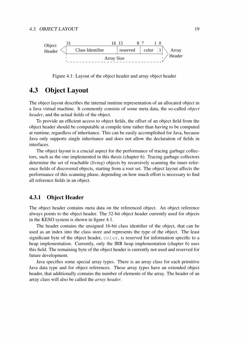
Figure 4.1: Layout of the object header and array object header
4.3 Object Layout
The object layout describes the internal runtime representation of an allocated object ina Java virtual machine. It commonly consists of some meta data, the so-called objectheader, and the actual fields of the object.
To provide an efficient access to object fields, the offset of an object field from theobject header should be computable at compile time rather than having to be computedat runtime, regardless of inheritance. This can be easily accomplished for Java, becauseJava only supports single inheritance and does not allow the declaration of fields ininterfaces.
The object layout is a crucial aspect for the performance of tracing garbage collec-tors, such as the one implemented in this thesis (chapter 6). Tracing garbage collectorsdetermine the set of reachable (living) objects by recursively scanning the inner refer-ence fields of discovered objects, starting from a root set. The object layout affects theperformance of this scanning phase, depending on how much effort is necessary to findall reference fields in an object.
4.3.1 Object Header
The object header contains meta data on the referenced object. An object referencealways points to the object header. The 32-bit object header currently used for objectsin the KESO system is shown in figure 4.1.
The header contains the unsigned 16-bit class identifier of the object, that can beused as an index into the class store and represents the type of the object. The leastsignificant byte of the object header, color, is reserved for information specific to aheap implementation. Currently, only the IRR heap implementation (chapter 6) usesthis field. The remaining byte of the object header is currently not used and reserved forfuture development.
Java specifies some special array types. There is an array class for each primitiveJava data type and for object references. These array types have an extended objectheader, that additionally contains the number of elements of the array. The header of anarray class will also be called the array header.

20 CHAPTER 4. KESO RUNTIME DATA STRUCTURES
ReferenceObject
Array Header
element 0element 1element 2element 3
incr
easi
ng m
emor
y ad
dres
ses
Figure 4.2: Layout of Array Types
4.3.2 Array Classes
Array classes not only differ in their header from non-array classes, they also use adifferent object layout, which is shown in figure 4.2. The elements are simply put behindthe array header, starting with the element at index 0 to the higher indices.
To scan an array of object references, the garbage collector only needs a simple loop,where the length of the array can be used as loop counter and array index.
4.3.3 Non-Array Classes
Traditional Object Layout
The traditional approach for the object layout is illustrated in figure 4.3, and was initiallyalso used in the KESO system. The example shows the object layout for a class C, thatis a subclass of class B, which in turn is a subclass of class A. In the traditional objectlayout, non-reference fields and reference fields are grouped together for each class inthe class hierarchy. The order in which the fields of each class are put after the objectheader is starting with the most general class (A in the example) to the most specializedclass (C in the example).
To scan the reference fields of an object, for each class in the type hierarchy ofthe object, the number of reference fields of the class and the offset of the referencefields (or, alternatively, the number of bytes occupied by non-reference fields) need tobe stored. This can be done in two ways:
First, for each class, the offset and number of reference fields of the class and each ofits superclasses can be stored in the class descriptor of the class, which would increase

4.3. OBJECT LAYOUT 21
non−reference
Cla
ss B
fieldsreference
fields
non−reference
Cla
ss C
fieldsreference
fields
ReferenceObject
non−reference
Cla
ss A
fieldsreference
fieldsoffset (A)
offset (B)
offset (C)
# references (A)
# references (B)
# references (C)incr
easi
ng m
emor
y ad
dres
ses
Object Header
Figure 4.3: Traditional Object Layout (Class C extends B extends A)
the memory required by the class store, depending on the depth of the type hierarchy2.Alternatively, the garbage collector would have to determine each super class at
runtime and read offset and number of reference fields from the class descriptors of allsuperclasses, which would significantly complicate the scan process.
Generally, to scan an object, two nested loops would be required, the outer onefor climbing the type hierarchy and the inner loop for reading offset and number ofreferences and scanning the references for each class on the type hierarchy.
Bidirectional Object Layout
To facilitate the scanning phase of the garbage collection, the traditional object layoutwas replaced by a bidirectional object layout similar to the one proposed in the SableVMproject [Gag02, GH01]. The layout used in KESO is shown in figure 4.4 for the sameclass that the traditional layout was illustrated with. Contrary to the traditional layout,an object now grows in both directions from the object header, where reference fieldsare put before and non-reference fields are put after the object header. The orderingremains the same, i.e. starting with the most generic class (A) to the most specializedclass (C). For an object with reference fields, the object header is now not placed in thebeginning of the object, but behind the reference fields, thus the object reference and thestarting address of the object usually differ in the bidirectional object layout. For each
2Because the class descriptors in the KESO class store need to be of equal size, the array containingoffset and number of reference fields for each class would either have to be stored outside of the classstore, or the maximum depth of the type hierarchy would have to be limited.

22 CHAPTER 4. KESO RUNTIME DATA STRUCTURES
referenceoffsets
fieldsreference
fieldsreference
fieldsreference
non−referencefields
non−referencefields
non−referencefields
ReferenceObject
Object Header
A
C
B
Object begin
A
B
Caddr
esse
sm
emor
yin
crea
sing
C
A
B
Figure 4.4: Bidirectional Object Layout (Class C extends B extends A)
class, a reference offset can be identified, that specifies the number of reference fields ofa class (including inherited reference fields). Knowledge of the reference offset is alsosufficient to compute the difference between the beginning of an object and the objectheader. Thus, for each class, only the reference offset needs to be stored in the classstore.
The offset of a field from the object header is still constant and computable at com-pile time, so field accesses remain efficient with the bidirectional layout.
When scanning an object, the garbage collector now only needs to read the referenceoffset from the class descriptor and read the references ahead of the object header. Onlya regular loop is required where the reference offset can directly be used for the loopcounter. The bidirectional offset thus saves both, computing time and memory accessesfor the scanning phase of the garbage collector, plus it reduces the memory required forthe class descriptor of each class.

Chapter 5
OSEK Abstraction Layer
Since KESO is built on top of an OSEK [OSE05] operating system, the OSEK conceptsneed to be made available to application developers on the Java level. A Java classlibrary and Java abstractions to OSEK system objects have been created for this task.
OSEK systems are configured with a configuration file described in the OSEK im-plementation language (OIL) [OSE04]. Most of the parameters and defined system ob-jects of the generated OSEK system are also required in the build process of the KESOsystem.
To eliminate the need for specifying this information in two separate configurations,the OSEK system configuration parameters have been integrated with the KESO con-figuration parameters in a single KESO system configuration file. The OIL configura-tion file for the underlying OSEK system is then automatically generated by the KESObuilder from the KESO configuration file. This provides the application developer witha single point for configuring the entire system.
Several goals can be identified for the OSEK abstraction layer:
• Create an object-oriented view on OSEK concepts such as Tasks and Resources
• While the object-oriented abstraction is always desirable from the perspective ofsoftware engineering, it is not always a viable choice. Because resources areusually very limited on the KESO target platforms, a tradeoff between abstractionand overhead has to be made. In some cases, e.g. OSEK Events, the advantages ofan object-oriented abstraction are outweighed by the overhead going along withthe abstraction and different solutions have to be considered.
• As a major goal of the whole KESO system, strong isolation of domains is alsoa goal of the OSEK abstraction layer. Accesses to OSEK system services needto be restricted to provide this isolation. As an example, it must be possible torestrict access to a certain OSEK Resource to a domain, if this is eligible for theuser application.
23
24 CHAPTER 5. OSEK ABSTRACTION LAYER
• The Java class library providing access to the OSEK system services should bemodeled closely to the original OSEK interface. This helps providing a familiarprogramming interface to OSEK application developers, easing the transition toapplication development for the KESO system.
Knowledge of the OSEK OS specification [OSE05] and the OSEK implementation lan-guage specification [OSE04] is presumed throughout this chapter.
This chapter is structured as follows: Section 5.1 gives an overview on the generaldesign decisions made for the OSEK abstraction layer. The object abstractions weresimilarly implemented for the different OSEK concepts and the general implementationis described in section 5.2. Sections 5.3–5.7 cover implementation details on the variousOSEK topics. Finally, section 5.8 discusses some problems, that arise by the use ofportals, and the used solutions.
5.1 Conceptual DesignFor each class of OSEK system services, as classified by the OSEK specification, aservice class has been created, that provides a static method for each OSEK systemservice function, plus some additional functions, such as a name service, that enforcesaccess restrictions to the system services on the Java language level.
5.1.1 Magic MethodsThe system service methods of the KESO class library need to call the OSEK systemservices in the generated C code, which is not possible with the use of pure Java code.The Java class library makes heavy use of so-called magic methods, i.e. Java methodsthat are specially treated by the KESO builder.
Special code for a magic method can either be inserted at the call-side, removing theinvocation of the magic method, or in the body of the magic method, leaving the call ofthe magic method untouched. The first variant corresponds to an inlining of the magicmethod.
The preferable way mostly depends on the complexity of the generated code. In-tercepting magic methods at the call-side can save the overhead of a method call, butis only suitable for short code fragments, whereas leaving the calls to a magic methoduntouched and generating special code in the method body instead is appropriate forlarger portions of code.
5.1.2 Access Restrictions to OSEK ServicesThe OSEK abstraction layer must ensure, that the isolation of domains is not weakenedby the inappropriate use of the OSEK system services. To ensure this, a mechanism
5.1. CONCEPTUAL DESIGN 25
needs to be provided that allows to restrict the access to certain system services.For instance, a Resource might be created to synchronize two Tasks of the same
domain. In such cases, it is desirable, that Tasks of other domains are not able to use theGetResource() service on that Resource. On the other hand, a Resource could alsobe used to synchronize Tasks of two different domains, that, for instance, both accessa periphery device. Therefore, the OSEK abstraction layer supports both global anddomain local object abstractions.
The services classes, that an access restriction was found to be useful to, are
1. Resource Service: Provide domain local Resources, that are only visible inside ofa domain and can be used for synchronization of Tasks within the same domain(see example above).
2. Task Management: The activation of other Tasks through the use of the Chain-Task() and the ActivateTask() services is restricted to Tasks within thesame domain.
3. Alarm Service: Services of this class allow the modification, activation and can-cellation of Alarms. Alarms are therefore assigned to a domain and the use ofthe system services is restricted to Alarms within the same domain as the callingTask.
Access restrictions are enforced on the language level. Object abstractions have beencreated in the classes Resource, Alarm and Task. Instances of these classes willbe called system objects (SO). The SOs are automatically created by the KESO builderusing the information from the KESO configuration file. Affected system services donot further check the domain of the calling Task and the domain of the system object(that may be another Task, a Resource or an Alarm), but require a reference to therespective system object as a parameter where OSEK uses plain identifiers on the Clevel. A name service is provided, that allows Tasks to acquire references to KESOsystem objects, by referencing the objects by their name as configured in the systemconfiguration file1. The name service does only return references of local SOs within thesame domain as the caller and references to global SOs to the caller, thereby restrictingthe use of system services by limiting the access to SOs.
5.1.3 Provision of OSEK Constants and IdentifiersWhere no access restrictions are required and object abstractions are not required dueto other reasons, the OSEK Identifiers are directly made available on the Java languagelevel. This affects Counters, Events and Application-Modes. For each of these, a Java
1These are the same identifiers, that would be used when programming C code for an OSEK applica-tion.
26 CHAPTER 5. OSEK ABSTRACTION LAYER
Resource System Objects
null
Resource Index0 1 2
Res
ourc
e N
ames
ResourceA
ResourceB
ResourceC
1
2 3
1
0 5
1
4
Domain IDs
Resource Name Service
5
ResourceA obj
ResourceID: 0
ResourceB obj
ResourceID: 1
ResourceC obj
ResourceID: 2
ResourceC obj
ResourceID: 3
ResourceC obj
ResourceID: 4
Lookup Matrix
(a) Name service example for Resources
DOMAIN NAME IDDomainA 0DomainB 1
DomainZero 2
(b) Domains
RESOURCE NAME ID SCOPE
ResourceA 0 DomainBResourceB 1 global
ResourceC1 2 DomainAResourceC2 3 DomainBResourceC3 4 global
Invalid Resource 5 -
(c) Resources
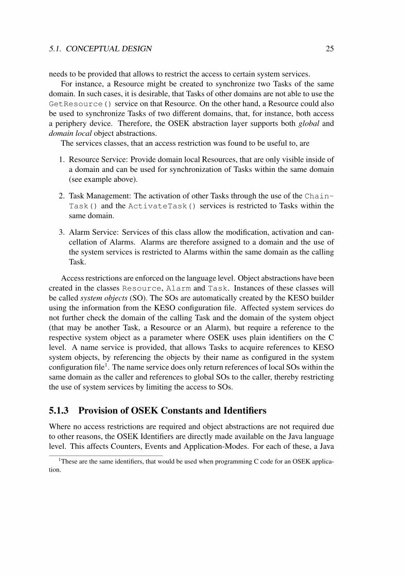
Figure 5.1: Name Service Implementation
class is automatically generated by the KESO autoclass generator, that determines theidentifiers and the assigned values from the KESO configuration file. These Java classescontain a final static field for each identifier with the assigned value, that can be used inthe Java applications similar to the use of OSEK identifiers in C applications.
5.2 Object Abstractions and Name Service
The object abstractions and the name service have been similarly implemented forTasks, Resources and Alarms. Differences are covered in the sections dedicated to eachOSEK topic below.
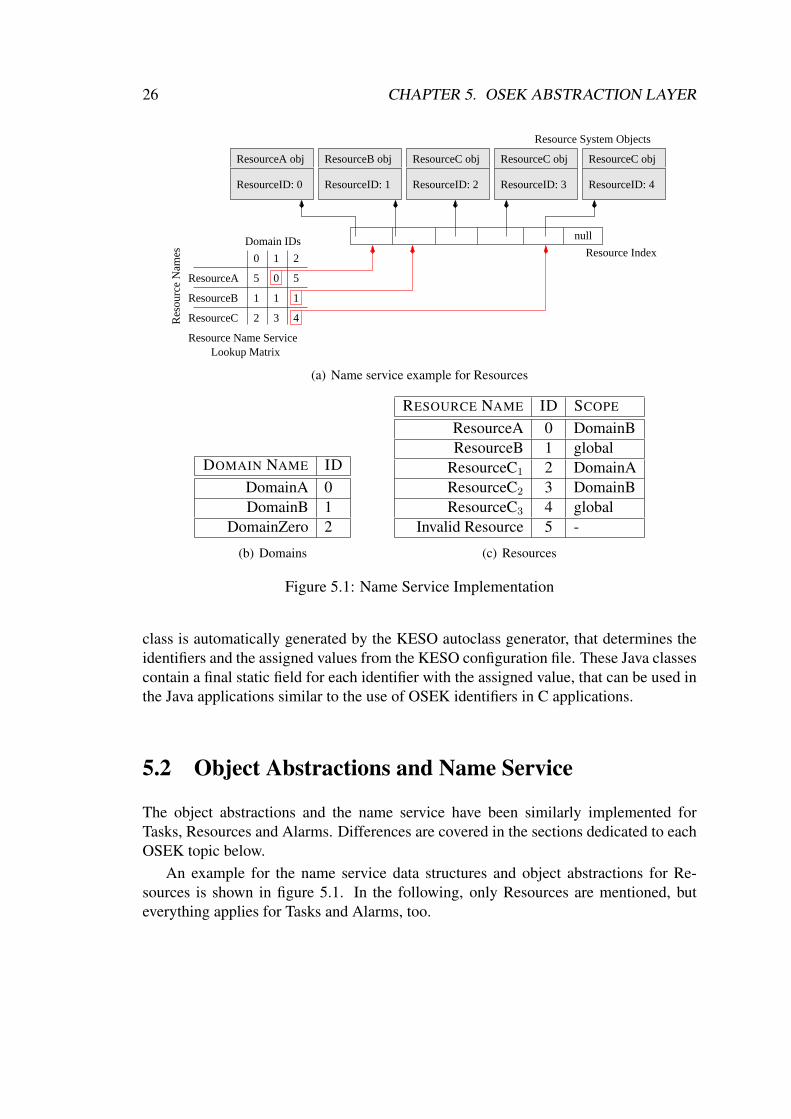
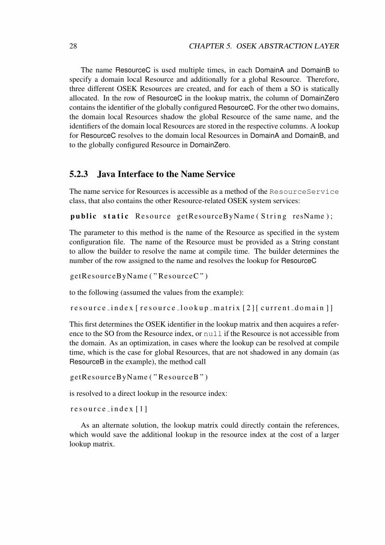
An example for the name service data structures and object abstractions for Re-sources is shown in figure 5.1. In the following, only Resources are mentioned, buteverything applies for Tasks and Alarms, too.

5.2. OBJECT ABSTRACTIONS AND NAME SERVICE 27
5.2.1 General DescriptionFor each Resource, a Resource SO is created at compile time by the KESO builder. TheSO contains a private field with the OSEK identifier of the Resource represented by theSO. When the GetResource() service is called on the Java level with the SO, thebuilder compiles it to a call to the OSEK GetResource() service on the C level anduses the OSEK identifier contained in the SO.
The references to the SOs are managed in an array, the Resource index. The OSEKidentifier of a Resource can be used as an index into this array to acquire the reference ofthe associated SO. Additionally, a special value INVALID RESOURCE is introduced,that is assigned the null reference2.
For the name service, a matrix mapping a Resource name and a domain identifierto an OSEK identifier is created, the Resource name service lookup matrix. The lookupmatrix contains a row for each Resource name and a column for each domain, includingDomainZero. Each element of the matrix either contains the OSEK identifier of theResource with the respective name, if that Resource is visible within the domain, or elsethe INVALID RESOURCE identifier. In case the same name is used multiple times, onlyone row is created for the name. The elements in this row then contain the appropriateOSEK identifier for the Resource visible within that domain, where a domain localResource shadows a global Resource with the same name.
5.2.2 Explanation of the ExampleFigure 5.1 shows an example scenario for a Resource name service. The available do-mains and the associated domain identifiers are shown in figure 5.1(b), including thesystem domain DomainZero. The configured Resources with their OSEK identifiersand scope are shown in figure 5.1(c). The scope specifies the domain a Resource isassigned to, or global if the Resource is accessible in all domains.
ResourceA shows the case of a domain local Resource, which is only accessiblefrom DomainB. The row of ResourceA in the lookup matrix contains the OSEK iden-tifier of ResourceA in the column of DomainB. In the columns of the other two do-mains, the special identifier INVALID RESOURCE is stored. A lookup for ResourceAtherefore resolves to a reference to the appropriate SO if invoked in DomainB. In theother two domains, the lookup resolves to the null reference, which represents theINVALID RESOURCE.
ResourceB illustrates the case of a global Resource. The row of ResourceB in thelookup matrix contains the OSEK identifier of the Resource for all domains. Therefore,a lookup of ResourceB resolves to a reference to the valid SO in every domain.
2OSEK already specifies an identifier INVALID TASK. For Tasks, this identifier is used, but newidentifiers have been created for Resources and Alarms. In either case, the invalid objects are alwaysrepresented by the null reference on the Java level.
28 CHAPTER 5. OSEK ABSTRACTION LAYER
The name ResourceC is used multiple times, in each DomainA and DomainB tospecify a domain local Resource and additionally for a global Resource. Therefore,three different OSEK Resources are created, and for each of them a SO is staticallyallocated. In the row of ResourceC in the lookup matrix, the column of DomainZerocontains the identifier of the globally configured ResourceC. For the other two domains,the domain local Resources shadow the global Resource of the same name, and theidentifiers of the domain local Resources are stored in the respective columns. A lookupfor ResourceC resolves to the domain local Resources in DomainA and DomainB, andto the globally configured Resource in DomainZero.
5.2.3 Java Interface to the Name Service
The name service for Resources is accessible as a method of the ResourceServiceclass, that also contains the other Resource-related OSEK system services:
p u b l i c s t a t i c Resource getResourceByName ( S t r i n g resName ) ;
The parameter to this method is the name of the Resource as specified in the systemconfiguration file. The name of the Resource must be provided as a String constantto allow the builder to resolve the name at compile time. The builder determines thenumber of the row assigned to the name and resolves the lookup for ResourceC
getResourceByName ( ” ResourceC ” )
to the following (assumed the values from the example):
r e s o u r c e i n d e x [ r e s o u r c e l o o k u p m a t r i x [ 2 ] [ c u r r e n t d o m a i n ] ]
This first determines the OSEK identifier in the lookup matrix and then acquires a refer-ence to the SO from the Resource index, or null if the Resource is not accessible fromthe domain. As an optimization, in cases where the lookup can be resolved at compiletime, which is the case for global Resources, that are not shadowed in any domain (asResourceB in the example), the method call
getResourceByName ( ” ResourceB ” )
is resolved to a direct lookup in the resource index:
r e s o u r c e i n d e x [ 1 ]
As an alternate solution, the lookup matrix could directly contain the references,which would save the additional lookup in the resource index at the cost of a largerlookup matrix.
5.3. TASK MANAGEMENT 29
5.2.4 Related IssuesGlobal Objects violate the domain isolation criterion, that a reference to the same objectnever crosses a domain boundary. This is, however, not a problem in the case of theAlarm and Resource SOs, as these
• do not contain any reference fields, and subclasses of the Alarm and Resourceclasses must not be created. They can therefore not be used as a container totransport references from one domain to another.
• are immortal objects and not subject to garbage collection. If they were, theywould possibly be reclaimed by the garbage collector, that only determines thereachability within one domain.
The first of the above conditions is not satisfied by Task SOs, because subclasses ofthe Task class can be created and these SOs could therefore be abused to transportreferences across a domain boundary. Therefore, Tasks cannot be configured globallyand always have to belong to a domain.
The data structures are only created if they are required, e.g. if Resources are notused in the system, the Resource index and the Resource lookup matrix are not created.This reduces the size of the KESO system.
5.3 Task ManagementOSEK allows to query the identifier of the current Task. Similar to the current domain,a reference to the SO of the current Task is stored in a global field current task.
Besides the OSEK identifier of a Task, the associated SO additionally contains thedomain identifier of the domain that the Task was configured in (field domain id) andthe identifier of the domain that the Task is currently running in, the effective domain(field e domain id). The configured domain and the effective domain may differ incase the Task makes use of portal services, see section 5.3.1.
Upon a Task switch, the current Task and the current domain need to be set for thescheduled Task. They also need to be updated for interrupt service routines and Alarmcallback functions, but these two are described in section 5.4 and section 5.7. Upona Task switch, immediately before scheduling the new Task, the PreTaskHook() isinvoked by the OSEK system. KESO uses this hook to perform the update operationsfor the current Task and the current domain. First, the OSEK ID of the current Task isacquired using the GetTaskID() OSEK service. The Task ID is then used to lookupa reference to the SO of the Task in the Task index. This reference is set as the currentTask, if the effective domain equals the configured domain of the Task, or to null,which represents the INVALID TASK on the Java level. The effective domain of the

30 CHAPTER 5. OSEK ABSTRACTION LAYER
current Task is set as the current domain. This is sufficient to setup the proper runtimeenvironment after each rescheduling.
5.3.1 Implementation of PortalsKESO portals can be used to allow a Task the execution of code within another domain,the service domain, via a limited set of portal services offered by that domain.
From a conceptional perspective, one would then assume, that the code executed inthe other domain is executed by a service Task belonging to that domain. This approachis, however, difficult to implement on an OSEK system. The service Task would haveto be configured with a fixed priority. Switching from the Task invoking the portal tothe service Task could only be handled by close-by or equal priorities combined witha blocking of the invoking Task, which is only possible using Events. However, thesame service can be used by multiple Tasks, and for each Task the service should beexecuted with the priority of the invoking Task. This could only be solved by addinga dedicated service Task with an appropriate priority for each Task that could possiblyuse the service, along with Events for each pairing. This is not a feasible solution.
Instead, no service Tasks are created at all and the portal call is actually handledby the invoking OSEK Task, which is—for the duration of the portal call—migrated tothe service domain. Therefore, for each Task, the configured domain and the effectivedomain can be distinguished, where the former represents the domain that the Task wasassigned to in the configuration, and the latter represents the domain that the Task iscurrently running in. In case of a portal call, the effective domain is set to the domainidentifier of the service domain. This effectively changes the runtime environment ofthe Task to the service domain, i.e. the Tasks have access to the SOs of the servicedomain through the name service, to the static variables of the service domain, andallocate objects from the heap of the service domain.
While a Task is executing code in a service domain, the GetTaskID() service al-ways returns INVALID TASK. This is necessary, because SOs must not cross a domainboundary, not even in copied form (see section 5.8).
Figure 5.2 shows an example for a Task (TaskA) that uses portal services of anotherdomain. The configured domain of TaskA is DomainA with the identifier 0. The Taskfirst uses a portal of DomainB, and while executing code in DomainB invokes a portalof its configured domain. The changes of the effective domain identifier in the SO ofthe Task as well as the respective values of the current Task and the current domainare shown in the figure. Notably, when a Task migrates back to its configured domainthrough another portal call as the example Task, the current Task contains a valid ref-erence to the SO of the Task, even though the presence in the configured domain isthrough the use of a portal.
An important aspect in this context is the layout of the Task stacks used by KESO,which is also illustrated in figure 5.2. The stack of a Task that migrates among domains

5.3. TASK MANAGEMENT 31
TaskA_obj
task_id: 5
domain_id: 0
e_domain_id: 0
TaskA_obj
task_id: 5
domain_id: 0
e_domain_id: 0
TaskA_obj
task_id: 5
domain_id: 0
e_domain_id: 1
Reference locals
Scalar locals
End of Linked List
Framelink
Reference locals
Scalar locals
Reference locals
Scalar locals
End of Linked List
Reference locals
Scalar locals
End of Linked List
System Objectof TaskA in thevarious statescu
rren
t_ta
sk
curr
ent_
dom
ain
0
0
1
ref
to S
Ore
f to
SO
null
task_idstack_index
Stackframelaunch()
Stackframeb()
StackframedomB_portal()
StackframedomA_portal()
Portal Pointer
ListOfReferences
Domain ID: 1
ListOfReferences
Portal Pointer
Domain ID: 0
ListOfReferences
Domain ID: 0
End of Stack (0)
DomainA (Id: 0) DomainB (Id: 1)
Stack (TaskA)
b() { ...
} ... domB_portal();
domB_portal() { ...
} ... domA_portal();
domA_portal() { ...
} ... WaitEvent();
Portal
Portal
launch() { ...
} ... b();
Figure 5.2: Portal implementation and Layout of a KESO Task Stack
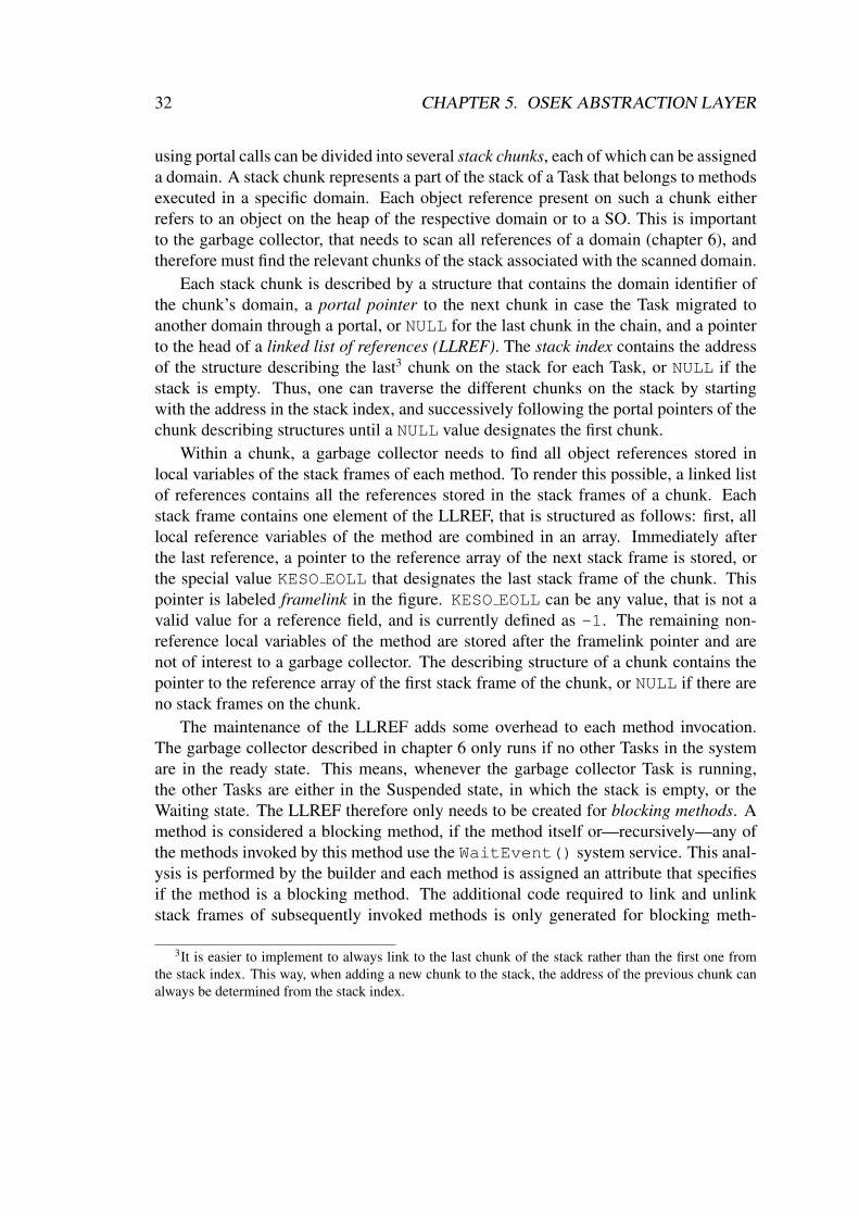
32 CHAPTER 5. OSEK ABSTRACTION LAYER
using portal calls can be divided into several stack chunks, each of which can be assigneda domain. A stack chunk represents a part of the stack of a Task that belongs to methodsexecuted in a specific domain. Each object reference present on such a chunk eitherrefers to an object on the heap of the respective domain or to a SO. This is importantto the garbage collector, that needs to scan all references of a domain (chapter 6), andtherefore must find the relevant chunks of the stack associated with the scanned domain.
Each stack chunk is described by a structure that contains the domain identifier ofthe chunk’s domain, a portal pointer to the next chunk in case the Task migrated toanother domain through a portal, or NULL for the last chunk in the chain, and a pointerto the head of a linked list of references (LLREF). The stack index contains the addressof the structure describing the last3 chunk on the stack for each Task, or NULL if thestack is empty. Thus, one can traverse the different chunks on the stack by startingwith the address in the stack index, and successively following the portal pointers of thechunk describing structures until a NULL value designates the first chunk.
Within a chunk, a garbage collector needs to find all object references stored inlocal variables of the stack frames of each method. To render this possible, a linked listof references contains all the references stored in the stack frames of a chunk. Eachstack frame contains one element of the LLREF, that is structured as follows: first, alllocal reference variables of the method are combined in an array. Immediately afterthe last reference, a pointer to the reference array of the next stack frame is stored, orthe special value KESO EOLL that designates the last stack frame of the chunk. Thispointer is labeled framelink in the figure. KESO EOLL can be any value, that is not avalid value for a reference field, and is currently defined as -1. The remaining non-reference local variables of the method are stored after the framelink pointer and arenot of interest to a garbage collector. The describing structure of a chunk contains thepointer to the reference array of the first stack frame of the chunk, or NULL if there areno stack frames on the chunk.
The maintenance of the LLREF adds some overhead to each method invocation.The garbage collector described in chapter 6 only runs if no other Tasks in the systemare in the ready state. This means, whenever the garbage collector Task is running,the other Tasks are either in the Suspended state, in which the stack is empty, or theWaiting state. The LLREF therefore only needs to be created for blocking methods. Amethod is considered a blocking method, if the method itself or—recursively—any ofthe methods invoked by this method use the WaitEvent() system service. This anal-ysis is performed by the builder and each method is assigned an attribute that specifiesif the method is a blocking method. The additional code required to link and unlinkstack frames of subsequently invoked methods is only generated for blocking meth-
3It is easier to implement to always link to the last chunk of the stack rather than the first one fromthe stack index. This way, when adding a new chunk to the stack, the address of the previous chunk canalways be determined from the stack index.
5.3. TASK MANAGEMENT 33
ods. If, for instance, a blocking method invokes a non-blocking method, the LLREFis built to the level of the blocking method, but not further on the code path of thenon-blocking method. This analysis is performed across portal calls, i.e. a new chunkwith the corresponding describing structure is only created for portal calls that use theWaitEvent() service on any of the possible code paths.
5.3.2 Task-Related System ServicesA class TaskService provides the Task-related system services, that allow the acti-vation of other Tasks, the termination of the current Task and the explicit triggering of areschedule for non-preemptible Tasks. Furthermore, the current Task and the state of aTask may be queried.
All services, that require a Task identifier to be passed on the C level, require aTask SO on the Java level. Therefore, these services are restricted to Tasks within thesame domain4. The following summarizes in short how the different services wereimplemented:
• GetTaskID(): A call to this service is replaced at the call-side with the globalcurrent Task field.
• TerminateTask() and Schedule(): These services are replaced at thecall-side with calls to the respective OSEK services, without any additional over-head. For TerminateTask(), additional code is inserted to clear the stack bystoring NULL in the appropriate field of the stack index.
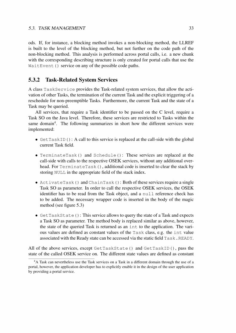
• ActivateTask() and ChainTask(): Both of these services require a singleTask SO as parameter. In order to call the respective OSEK services, the OSEKidentifier has to be read from the Task object, and a null reference check hasto be added. The necessary wrapper code is inserted in the body of the magicmethod (see figure 5.3)
• GetTaskState(): This service allows to query the state of a Task and expectsa Task SO as parameter. The method body is replaced similar as above, however,the state of the queried Task is returned as an int to the application. The vari-ous values are defined as constant values of the Task class, e.g. the int valueassociated with the Ready state can be accessed via the static field Task.READY.
All of the above services, except GetTaskState() and GetTaskID(), pass thestate of the called OSEK service on. The different state values are defined as constant
4A Task can nevertheless use the Task services on a Task in a different domain through the use of aportal, however, the application developer has to explicitly enable it in the design of the user applicationby providing a portal service.
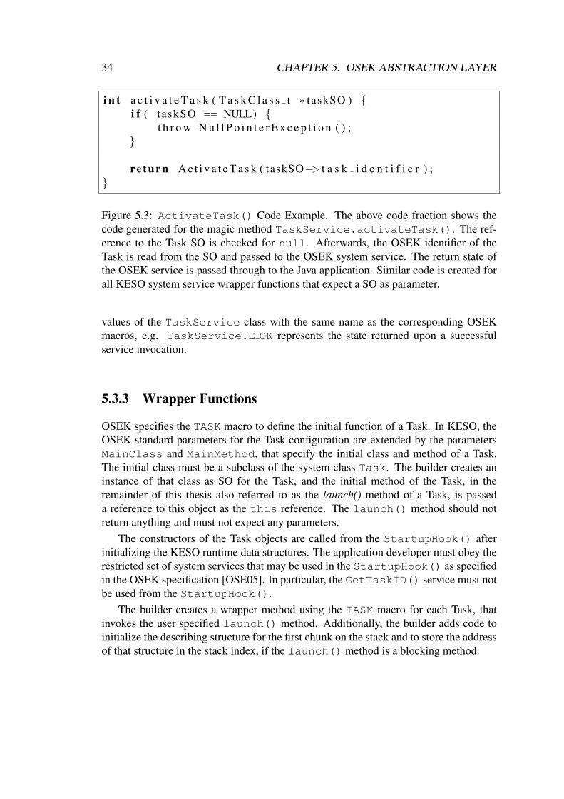
34 CHAPTER 5. OSEK ABSTRACTION LAYER
i n t a c t i v a t e T a s k ( T a s k C l a s s t ∗ taskSO ) {i f ( taskSO == NULL) {
t h r o w N u l l P o i n t e r E x c e p t i o n ( ) ;}
re turn A c t i v a t e T a s k ( taskSO−> t a s k i d e n t i f i e r ) ;}
Figure 5.3: ActivateTask() Code Example. The above code fraction shows thecode generated for the magic method TaskService.activateTask(). The ref-erence to the Task SO is checked for null. Afterwards, the OSEK identifier of theTask is read from the SO and passed to the OSEK system service. The return state ofthe OSEK service is passed through to the Java application. Similar code is created forall KESO system service wrapper functions that expect a SO as parameter.
values of the TaskService class with the same name as the corresponding OSEKmacros, e.g. TaskService.E OK represents the state returned upon a successfulservice invocation.
5.3.3 Wrapper Functions
OSEK specifies the TASK macro to define the initial function of a Task. In KESO, theOSEK standard parameters for the Task configuration are extended by the parametersMainClass and MainMethod, that specify the initial class and method of a Task.The initial class must be a subclass of the system class Task. The builder creates aninstance of that class as SO for the Task, and the initial method of the Task, in theremainder of this thesis also referred to as the launch() method of a Task, is passeda reference to this object as the this reference. The launch() method should notreturn anything and must not expect any parameters.
The constructors of the Task objects are called from the StartupHook() afterinitializing the KESO runtime data structures. The application developer must obey therestricted set of system services that may be used in the StartupHook() as specifiedin the OSEK specification [OSE05]. In particular, the GetTaskID() service must notbe used from the StartupHook().
The builder creates a wrapper method using the TASK macro for each Task, thatinvokes the user specified launch() method. Additionally, the builder adds code toinitialize the describing structure for the first chunk on the stack and to store the addressof that structure in the stack index, if the launch() method is a blocking method.
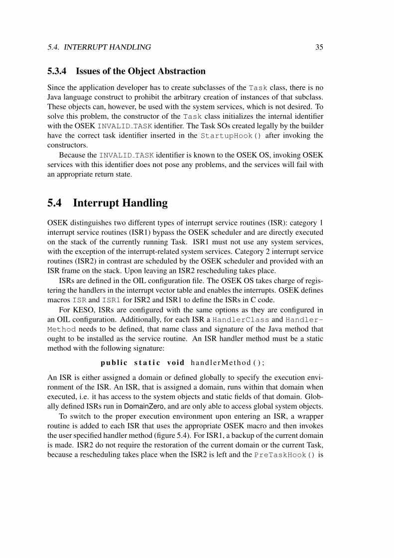
5.4. INTERRUPT HANDLING 35
5.3.4 Issues of the Object Abstraction
Since the application developer has to create subclasses of the Task class, there is noJava language construct to prohibit the arbitrary creation of instances of that subclass.These objects can, however, be used with the system services, which is not desired. Tosolve this problem, the constructor of the Task class initializes the internal identifierwith the OSEK INVALID TASK identifier. The Task SOs created legally by the builderhave the correct task identifier inserted in the StartupHook() after invoking theconstructors.
Because the INVALID TASK identifier is known to the OSEK OS, invoking OSEKservices with this identifier does not pose any problems, and the services will fail withan appropriate return state.
5.4 Interrupt Handling
OSEK distinguishes two different types of interrupt service routines (ISR): category 1interrupt service routines (ISR1) bypass the OSEK scheduler and are directly executedon the stack of the currently running Task. ISR1 must not use any system services,with the exception of the interrupt-related system services. Category 2 interrupt serviceroutines (ISR2) in contrast are scheduled by the OSEK scheduler and provided with anISR frame on the stack. Upon leaving an ISR2 rescheduling takes place.
ISRs are defined in the OIL configuration file. The OSEK OS takes charge of regis-tering the handlers in the interrupt vector table and enables the interrupts. OSEK definesmacros ISR and ISR1 for ISR2 and ISR1 to define the ISRs in C code.
For KESO, ISRs are configured with the same options as they are configured inan OIL configuration. Additionally, for each ISR a HandlerClass and Handler-Method needs to be defined, that name class and signature of the Java method thatought to be installed as the service routine. An ISR handler method must be a staticmethod with the following signature:
p u b l i c s t a t i c vo id hand le rMethod ( ) ;
An ISR is either assigned a domain or defined globally to specify the execution envi-ronment of the ISR. An ISR, that is assigned a domain, runs within that domain whenexecuted, i.e. it has access to the system objects and static fields of that domain. Glob-ally defined ISRs run in DomainZero, and are only able to access global system objects.
To switch to the proper execution environment upon entering an ISR, a wrapperroutine is added to each ISR that uses the appropriate OSEK macro and then invokesthe user specified handler method (figure 5.4). For ISR1, a backup of the current domainis made. ISR2 do not require the restoration of the current domain or the current Task,because a rescheduling takes place when the ISR2 is left and the PreTaskHook() is
36 CHAPTER 5. OSEK ABSTRACTION LAYER
ISR ( i s r a s c 0 r x ) {unsigned char db = c u r r e n t d o m a i n ; /∗ ISR1 o n l y ∗ /c u r r e n t d o m a i n = 0 ; /∗ 0 == Domain o f ISR ∗ /
i f ( c u r r e n t d o m a i n != 0 ) { /∗ ISR2 o n l y ∗ /c u r r e n t t a s k = NULL; /∗ ISR2 o n l y ∗ /
}rxIRQHandler ( ) ; /∗ u s e r s p e c i f i e d h a n d l e r ∗ /
c u r r e n t d o m a i n = db ; /∗ ISR1 o n l y ∗ /}
Figure 5.4: ISR wrapper function. Source lines marked with ISR1 or ISR2 only applyto wrapper routines for category 1 or respectively category 2 ISRs. isr asc0 rxis the OSEK identifier of the ISR as configured in the system configuration file,rxIRQHandler() is the handler method specified by the application developers.
invoked, that sets the correct values for both. The domain of the ISR is set as the currentdomain afterwards for any ISR category.
For category 2 ISRs, the current Task is additionally set to INVALID TASK, if theISR2 belongs to a different domain than the currently running Task. This is necessarybecause otherwise a Task object could migrate to a different domain through an ISR2.For ISR1, this is not required, because ISR1 must not use the GetTaskID() systemservice.
The user defined handler routine is then invoked and, for ISR1, the saved value ofthe current domain is restored before leaving the ISR1.
The OSEK system services related to interrupt handling allow the disabling andenabling of interrupts. These are provided as static methods by a class Interrupt-Service. Calls to these methods are intercepted at the call-side and replaced with callsto the OSEK services. These services may therefore be invoked without any overhead.
5.5 Event Mechanism
The Event mechanism allows extended Tasks to enter the Waiting state until one of theEvents the Task is waiting for is set. This is also the only way that an OSEK Task canpossibly block during its execution, which is an important aspect for garbage collection.
An Event is represented by its mask. The mask of an Event needs to contain a bitunique for each Task, that accesses the Event, because bit operations can be used tocreate masks containing multiple Events. It is possible, that two Events use the same

5.6. RESOURCE MANAGEMENT 37
mask, if there is no Task in the system that accesses both of the Events. The mask of anEvent is either configured manually in the configuration file or automatically generatedby the OSEK configurator. OSEK specifies, that the mask of each Event is accessiblevia the identifier of the Event in the code, and the identifiers can be used with any bitoperation.
In KESO, Events are also represented by their mask. There is no need to createan object abstraction for Events, since the setting and querying of Events for a Task isalready limited by the requirement for a Task SO. Furthermore, an object abstractionwould add a significant overhead to provide the creation of masks using bit operations.The mask of an Event is provided as a constant value with the name of the Event identi-fier in the class Events. This class is automatically generated from the information ofthe KESO configuration file. The builder computes an appropriate Event mask for eachEvent where automatic generation of the mask is configured, and the generated OIL filecontains the computed values of the mask. This prevents, that the OSEK configuratorcomputes different masks than the KESO builder.
The Event-related services are provided by the EventService class and imple-mented as follows:
• ClearEvent() and WaitEvent() both expect an Event mask as parameter.The mask can be constructed using the identifiers provided by the Events classand bit operations. Calls to these methods are replaced at the call-side with callsto the corresponding OSEK services.
• SetEvent() and GetEvent() are passed the SO of the Task that the serviceis to be performed on. SetEvent() additionally expects an Event mask. Themethod body of these services is replaced, whereby additional code to check thereference to the Task SO for null and to extract the Task identifier from the SOis added, similar to the wrapper code created for the Task services.
5.6 Resource Management
Resources allow the coordination of concurrent accesses of several Tasks to shared re-sources. KESO supports both, domain local Resources for the coordination of Taskswithin the same domain and global Resources for the inter domain coordination ofTasks. The implementation of the object abstraction for Resource has already beenextensively described in section 5.2.
There are only two system services related to Resource management, the Get-Resource() service, that allows to occupy an OSEK Resource, and the Release-Resource() service, that allows to release an occupied Resource. The reader is as-sumed to be familiar with the ceiling protocol used by OSEK systems in conjunction
38 CHAPTER 5. OSEK ABSTRACTION LAYER
with the Resource management, that plays a role in the synchronization of the garbagecollector implemented in chapter 6.
Both of the above services expect a Resource identifier on the C level and require aResource SO on the Java level. Unlike Task objects, Resource SOs cannot be createdby the user application. A Resource SO therefore always contains a valid Resourceidentifier.
Additional code that checks the SO reference for null and extracts the Resourceidentifier from the SO, needs to be inserted in the body of the magic methods, similar tothe wrapper code added for the Task services.
5.7 Alarms and Counters
OSEK provides a two-stage concept for processing recurring events, Alarms based onCounters.
5.7.1 Counters
A Counter is represented by its value that is measured in ticks. A Counter can eitherbe increased by hardware or by software. The OSEK specification does not furtherspecify this, but requires that OSEK implementations provide at least one Counter thatis derived from a hardware or software timer. Alarms are based on a Counter and expirewhen the Counter reaches a predefined counter value. In reaction to the expiration ofan Alarm, a Task can be activated, an Event for a Task can be set or an alarm callbackroutine can be invoked. Multiple Alarms can be based on the same Counter.
Since the number of available timers, that a Counter can be based on, is usuallyvery limited, Counters are only configured globally in KESO. OSEK associates a fewconstants to each Counter that are accessible via macros, such as the maximum al-lowed value of a Counter. On the Java level, these are provided as constants of theCounters class. The constants have the same name as the macros provided by OSEK,e.g. the maximum allowed value for the Counter with the identifier c1 is available asCounters.OSMAXALLOWEDVALUE c1.
5.7.2 Alarms
Alarms, on the other hand, can be configured as both, global and domain local objects.Object abstractions were introduced for Alarms as described in section 5.2. MultipleAlarms can use the same Counter, even if the Alarms are configured in different do-mains.
5.7. ALARMS AND COUNTERS 39
Scope of an Alarm
The scope of an Alarm restricts the use of the system services (e.g. a domain localAlarm can only be canceled by a Task within the same domain) and limits the reactionsto an Alarm:
• Activate a Task: This action can only activate Tasks within the same domain asthe Alarm. Global Alarms cannot use this action.
• Set an Event for a Task: The Event can only be set for Tasks within the samedomain as the Alarm. Global Alarms cannot use this action.
• Invoke a callback function: This is the only action possible for global Alarms.The callback function is executed in the domain of the Alarm, or DomainZero forglobal Alarms.
Wrapper Function for Alarm Callback Functions
OSEK specifies, that Alarm callback functions must be defined using the ALARMCALL-BACK macro. Very similar to ISRs, a wrapper function is created by the OSEK builderthat uses the macro and calls the user defined callback function. The callback function isspecified in the configuration file by the class and the signature of the callback method.The callback method must be static and can neither have parameters nor a return value.
The wrapper code created around the invocation of the user specified alarm callbackmethod is the same as for an ISR1, i.e. a backup of the current domain is taken and thecurrent domain is set to the domain of the Alarm associated with the callback functionbefore invoking the user defined callback method, and the saved domain is restoredafterwards.
Alarm Services
The Alarm-related system services are provided by the AlarmService class on theJava level. The Alarm services allow to query the properties of the underlying counterof an Alarm using the GetAlarmBase() service. A class AlarmBase has beenimplemented on the Java level that contains all the elements of the AlarmBaseTypestructure on the C level specified by the OSEK specification and can be used in the samemanner.
All functions that expect an Alarm identifier as parameter on the C level requirean Alarm SO on the Java level. Wrapper code has been added in these functions thatextracts the OSEK identifier of the SO to invoke the OSEK service and checks if thereference is null, similar to the wrapper code created for the Task services. Contraryto Task objects, Alarm SOs cannot be created by the user application. Thus, an AlarmSO always contains a valid Alarm identifier.

40 CHAPTER 5. OSEK ABSTRACTION LAYER
5.8 Problems Imposed by PortalsWhen passing object parameters to a portal, the referenced objects, including the transi-tive closure, are copied to the service domain. The object copies are allocated from theheap of the service domain.
This approach causes some problems when system objects are passed to a portalcall, as these are used to restrict the access to the services. When accessing an OSEKservice, a copy of a system object is of the same value as the original object. Therefore,portal calls would allow system objects to spread across domains and escape their scope.
To solve this problem, a marker interface NonCopyable was introduced to markclasses that are not to be copied across portal calls. Instead, when a NonCopyableobject is passed to a portal call, it is replaced by a null reference. The system objectclasses Alarm, Resource and Task implement this interface. Furthermore, the in-terface may be implemented by classes of the user application to prevent instances to becopied across portal calls.
Chapter 6
Memory Management
KESO was designed to allow the coexistence of different heap implementations. Eachdomain in a KESO system can choose a heap implementation for managing its heap.
Besides the heap implementation developed in this work, KESO already containeda very simple heap implementation, that does not provide any garbage collection. Theadvantage of this heap implementation is the short, constant and thus easily predictabletime required for the allocation of an object. However, since there is no way of releas-ing the memory of objects that are not required anymore, the memory requirements ofthe application must be exactly predictable and must not grow with the runtime of theapplication. This heap implementation is suitable for hard real-time systems where nooverhead for garbage collection can be tolerated.
The heap implementation developed in this work features a precise, incremental,tracing, non-moving mark-and-sweep garbage collector (GC). The reader is supposedto be familiar with garbage collection techniques, as they are not covered in this work.A survey on garbage collection techniques on uniprocessors is available in [Wil92].This heap implementation was named the IdleRoundRobin (IRR) heap implementation,because—from the viewing point of the application developer—the garbage collectionis performed at the idle time of the system, and because a single OSEK Task, thegarbage collector Task (GCT), manages multiple domains in a manner similar to RoundRobin (see section 6.6.1, Domain Selection). The OSEK Task of the garbage collectoris configured with the very lowest priority of all Tasks in the system, and is thereforeonly active when there is no other Task in the system in the Ready state, i.e. all otherTasks are either in the Suspended state or the Waiting state. This is a very advantageouspoint in time for garbage collection, because the stacks of Tasks in the Suspended stateare empty, and therefore the effort required to scan the root set of reachable objects isexpected to be minimal at this point.
The application developers have to ensure, that there is enough time for the garbagecollector to run, by integrating the garbage collector in the design process of the wholesystem just as any other user application. This approach can be termed cooperative
41
42 CHAPTER 6. MEMORY MANAGEMENT
garbage collection, as the cooperation of the application developer is required.As an incremental garbage collector, the GC process can be interrupted at any stage.
To ensure a low latency on interrupts (i.e. external events), which is crucial on real-time systems, the garbage collector was designed in a way, that restricts all criticalsections1 to constant complexity. The worst case reaction time to an incoming interruptis therefore low and easily predictable.
The remainder of this chapter is structured as follows: At first, the data structures ofthe IRR heap implementation is described in section 6.1, followed by a description ofthe coloring mechanism used by the IRR heap in section 6.2. Then, the implementationof the free memory list and the special list processing function listwalker(), thatallows traversal of the list with all critical sections being of O(1) (constant) complexity,is discussed (section 6.3). The listwalker() function is the base of both, the alloca-tor function (section 6.4) and the garbage collector (section 6.5). The discussion of thegarbage collector poses the main part of the chapter. The different phases of a garbagecollector cycle are explained in section 6.6. An interruption of the garbage collectorduring the scan phase imposes particular problems, that are identified and solved in sec-tion 6.7. Finally, the overhead and interrupt latency caused by the garbage collector arepresented in section 6.8.
6.1 Data Structures of the IdleRoundRobin HeapThis section describes the data structures deployed by the IRR heap in order to estab-lish fundamental knowledge required to understand the allocator and garbage collectorimplementations. The figures used for illustration also introduce the figure conventionsused later on in the more sophisticated illustrations.
6.1.1 Slot Division and BitmapAs every heap in the KESO system, an IRR heap is of a statically configured size thatcannot be changed at runtime. During the scan phase the garbage collector needs tokeep track of the parts of the domain heap that are used by living2 objects. The garbagecollector uses a bitmap to mark the occupied memory by setting corresponding bits inthe bitmap. Allocating one bit in the bitmap for each byte of the heap would be wasteful,since each object has a minimum size due to the object header, which is currently fourbytes. The heap is therefore divided in slots of a fixed, configurable length, the slot size.Each object occupies one or more consecutive slots on the heap. A slot is never shared
1The term critical section is used throughout this chapter to refer to a section of code, that is protectedby a blockade of interrupts when executed, i.e. interrupts are disabled straight before entering the criticalsection of code, and immediately reactivated after leaving the critical section of code.
2An object is said to be living if it is still reachable by the user applications.
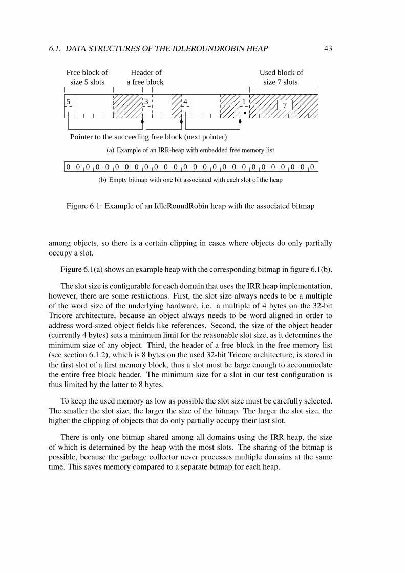
6.1. DATA STRUCTURES OF THE IDLEROUNDROBIN HEAP 43
������������
������������
����
����
��������
��������
����������������������������
����������������������������
5 13
Free block ofsize 7 slots
Used block ofsize 5 slots
4
a free blockHeader of
Pointer to the succeeding free block (next pointer)
7
(a) Example of an IRR-heap with embedded free memory list
0 0 0 0 0 0 0 0 0 0 0 0 0 0 0 00 0 0 00 0 0 0 0 0
(b) Empty bitmap with one bit associated with each slot of the heap
Figure 6.1: Example of an IdleRoundRobin heap with the associated bitmap
among objects, so there is a certain clipping in cases where objects do only partiallyoccupy a slot.
Figure 6.1(a) shows an example heap with the corresponding bitmap in figure 6.1(b).
The slot size is configurable for each domain that uses the IRR heap implementation,however, there are some restrictions. First, the slot size always needs to be a multipleof the word size of the underlying hardware, i.e. a multiple of 4 bytes on the 32-bitTricore architecture, because an object always needs to be word-aligned in order toaddress word-sized object fields like references. Second, the size of the object header(currently 4 bytes) sets a minimum limit for the reasonable slot size, as it determines theminimum size of any object. Third, the header of a free block in the free memory list(see section 6.1.2), which is 8 bytes on the used 32-bit Tricore architecture, is stored inthe first slot of a first memory block, thus a slot must be large enough to accommodatethe entire free block header. The minimum size for a slot in our test configuration isthus limited by the latter to 8 bytes.
To keep the used memory as low as possible the slot size must be carefully selected.The smaller the slot size, the larger the size of the bitmap. The larger the slot size, thehigher the clipping of objects that do only partially occupy their last slot.
There is only one bitmap shared among all domains using the IRR heap, the sizeof which is determined by the heap with the most slots. The sharing of the bitmap ispossible, because the garbage collector never processes multiple domains at the sametime. This saves memory compared to a separate bitmap for each heap.
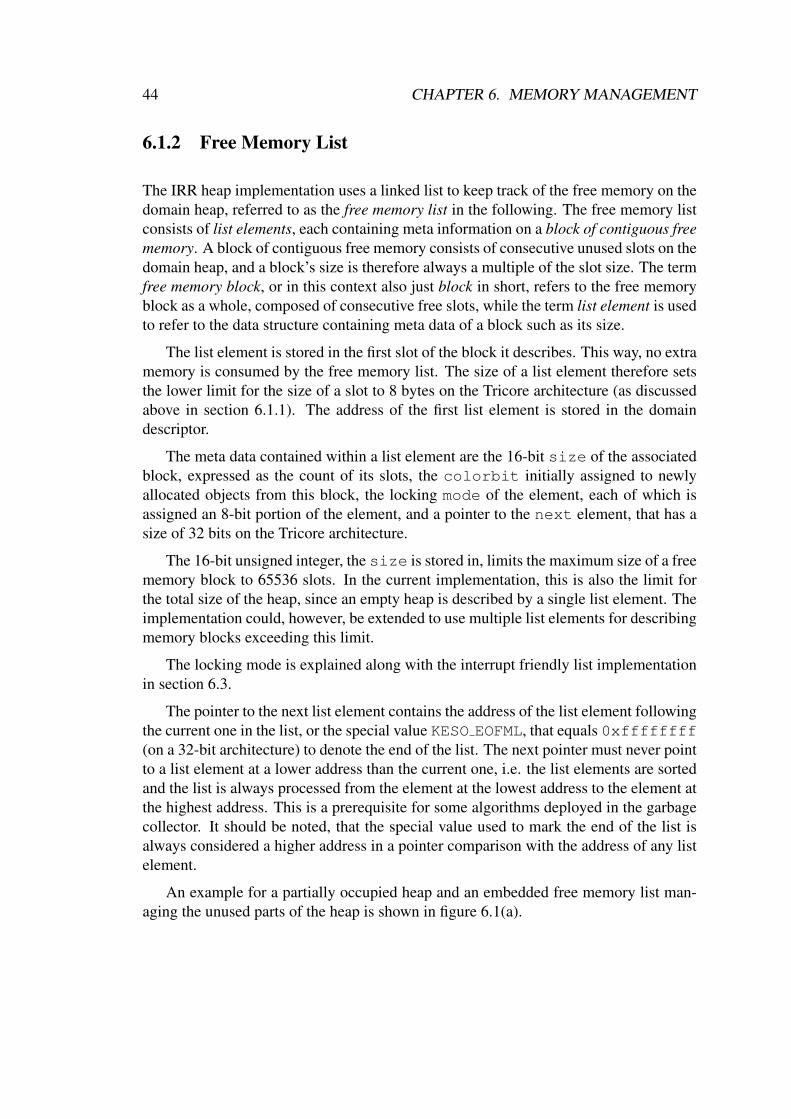
44 CHAPTER 6. MEMORY MANAGEMENT
6.1.2 Free Memory List
The IRR heap implementation uses a linked list to keep track of the free memory on thedomain heap, referred to as the free memory list in the following. The free memory listconsists of list elements, each containing meta information on a block of contiguous freememory. A block of contiguous free memory consists of consecutive unused slots on thedomain heap, and a block’s size is therefore always a multiple of the slot size. The termfree memory block, or in this context also just block in short, refers to the free memoryblock as a whole, composed of consecutive free slots, while the term list element is usedto refer to the data structure containing meta data of a block such as its size.
The list element is stored in the first slot of the block it describes. This way, no extramemory is consumed by the free memory list. The size of a list element therefore setsthe lower limit for the size of a slot to 8 bytes on the Tricore architecture (as discussedabove in section 6.1.1). The address of the first list element is stored in the domaindescriptor.
The meta data contained within a list element are the 16-bit size of the associatedblock, expressed as the count of its slots, the colorbit initially assigned to newlyallocated objects from this block, the locking mode of the element, each of which isassigned an 8-bit portion of the element, and a pointer to the next element, that has asize of 32 bits on the Tricore architecture.
The 16-bit unsigned integer, the size is stored in, limits the maximum size of a freememory block to 65536 slots. In the current implementation, this is also the limit forthe total size of the heap, since an empty heap is described by a single list element. Theimplementation could, however, be extended to use multiple list elements for describingmemory blocks exceeding this limit.
The locking mode is explained along with the interrupt friendly list implementationin section 6.3.
The pointer to the next list element contains the address of the list element followingthe current one in the list, or the special value KESO EOFML, that equals 0xffffffff(on a 32-bit architecture) to denote the end of the list. The next pointer must never pointto a list element at a lower address than the current one, i.e. the list elements are sortedand the list is always processed from the element at the lowest address to the element atthe highest address. This is a prerequisite for some algorithms deployed in the garbagecollector. It should be noted, that the special value used to mark the end of the list isalways considered a higher address in a pointer comparison with the address of any listelement.
An example for a partially occupied heap and an embedded free memory list man-aging the unused parts of the heap is shown in figure 6.1(a).
6.1. DATA STRUCTURES OF THE IDLEROUNDROBIN HEAP 45
6.1.3 Working Stack for the GC Scanning Phase
The working stack is an array of object references that is used by the garbage collectorduring the scanning phase to store references to objects that still need to be scanned.The stack pointer is an index into the working stack array and contains the index of thenext unused array element. Thus, pushing to the stack is a post-increment operation onthe stack pointer while popping references from the stack is a pre-decrement operation.The stack is empty when the stack pointer is 0.
The maximum size of the working stack has to be predictable, because the stackmust not overflow during the scanning. The scan algorithm implemented in the IRR-GC guarantees, that an object reference is never present on the working stack multipletimes. Thus, the worst-case size of the stack can easily be calculated as the maximumnumber of objects, that can be allocated from the heap, plus the number of immortalobjects that exist in the system.
The maximum number of objects, that can be allocated from an IRR heap, equalsthe number of slots on the heap. Immortal objects are allocated by the KESO builder,thus the number of immortal objects is known at compile time.
To further pursue the idea of cooperative garbage collection, the worst case size ofthe stack could be reduced with hints by the application developer, who could possiblyprovide a closer estimate on the maximum number of reachable objects in the system atthe time of garbage collection.
6.1.4 Managed Domains Array
As aforementioned, the IRR heap implementation creates a single Task for garbagecollection that manages all domains deploying this heap type. The managed domainsarray contains the domain identifiers of all domains managed by the GC and is used bythe domain selector function to determine the domain for a garbage collection cycle.
6.1.5 Garbage Collector Domain
The garbage collector of this heap can be interrupted during a garbage collection cy-cle. During certain phases of the garbage collection, it is important for the interruptingcode to know, if a garbage collection is currently being performed on the domain thecode runs in. This is explained in detail in section 6.7, where the interruptibility of thegarbage collector is discussed. The garbage collector domain (GC domain) contains theidentifier of the domain, that the IRR-GC is currently operating on, or the special iden-tifier INVALID DOMAIN, if the garbage collector is currently not running in a criticalphase.
46 CHAPTER 6. MEMORY MANAGEMENT
6.2 Coloring of ObjectsDuring the scan phase, the garbage collector performs a coloring of objects accordingto the tricolor marking scheme [Bak92]. The color field of an object header (sec-tion 4.3.1) is used to store the color of an object. Bit 0 of the color byte is always setto 1. This allows to distinguish the object header from object references, in which theleast significant bit is always cleared because of the alignment of the object header3.
To store the color, only one bit in the color byte of the object header is actuallyused, indicating whether the object is marked as black, gray or white. The distinctionbetween black and gray is made by the objects presence on the working stack of thegarbage collector. If the object is present on the working stack, it has not been scannedyet and its color corresponds to gray, else the object is not scanned in this cycle and thecolor corresponds to black4.
After each garbage collector cycle, the color of all objects that survived the cycleneeds to be reset to white for the next cycle. To achieve this with the least necessaryeffort, the meaning of the color bit is simply inverted after each garbage collectioncycle. The domain descriptor of each domain, that uses the IRR heap, contains a fieldthat stores the current value for colored (black, gray) objects.
6.3 Interrupt Friendly List ImplementationA crucial aspect of embedded real-time operating systems is minimizing the interruptlatency, which determines the worst-case reaction time to external events. For all op-erations that require a traversal of the free memory list, the IRR heap implementationprovides a generic and reentrant function listwalker(), that allows traversing thelist and applying a callback function to each list element. All critical sections are ofconstant complexity. The interrupt latency is thereby kept low and predictable.
To achieve this, each list element contains an 8-bit locking field, of which only onebit is actually used. The semantics of this bit is, that as long as it is set, the list elementmust not be removed from the list. It may, however, be resized. The locking bit is alsocalled the mode of the list element in the following, and always has a value of either 0(unlocked) or 1 (locked), indicating whether the element may be removed from the listor not.
The listwalker() function performs a single traversal of the list, calling a spec-ified callback function for each list element. The callback function may cause the ter-mination of the list traversal if no further processing is required.
3This is only true for architectures with an address capacity of 16 bits or higher. For 8-bit architectures,a different solution would have to be found.
4An object is either black because it has already been scanned in the garbage collector cycle or becauseit was allocated black during a garbage collector cycle.

6.3. INTERRUPT FRIENDLY LIST IMPLEMENTATION 47
The implementation of the listwalker() function is shown in figure 6.2, wheredomain t and listel t are the types of a domain descriptor structure and a listelement structure respectively. The callback function is of the type callback fct t.The function was slightly simplified by removing the special handling necessary for thefirst element.
6.3.1 Interface to the CallerThe listwalker() is passed a pointer to the domain descriptor structure in the pa-rameter domaindesc, which contains the beginning of the free memory list. Thispointer is also handed through to the callback function. The parameter cbparam canbe used by the application to pass an optional parameter to the callback function andis not used by the listwalker() itself. The parameter callback contains the ad-dress of the callback function. The callback function needs to conform to the interfacedescribed in section 6.3.2.
6.3.2 Interface to the Callback FunctionThe callback function is invoked for each list element in the free memory list and finallywith the special value KESO EOFML. Besides the addresses of the domain descriptorstructure and the optional parameter cbparam, it is passed the address of the cur-rently processed list element, the location of the pointer linking to the current element(prevNextPointer), which is either the next pointer of the preceding list elementor the head pointer in the domain descriptor structure for the first list element, and theoriginal locking mode of the current element. The callback function may cancel the listtraversal at any time by returning a 0 value, e.g. when the allocator has found a suitablememory block to satisfy the request. If further processing of the list is required, a valueof 1 has to be returned.
The listwalker() takes charge of acquiring and releasing the locks on the ele-ments. If the structure of the list is changed, however, the mode of the current elementcannot safely be restored by the listwalker(). An allocator might have removedthe current element and handed it to the application for instance—in that case, restoringthe locking mode would corrupt the memory occupied by an object of the application.The listwalker() detects a change to the list structure by checking if the linkingpointer still refers to the current element. If this is not the case, the callback functionneeds to restore the original locking mode, if the element is still a member of the freememory list, which is e.g. the case when new elements are inserted by the garbagecollector between the previous and the current element.
Interrupts are enabled while calling the callback function, however, it is guaranteed,that the current element, as well as the location with the pointer referring to the currentelement, is not removed asynchronously while the callback function processes it. If
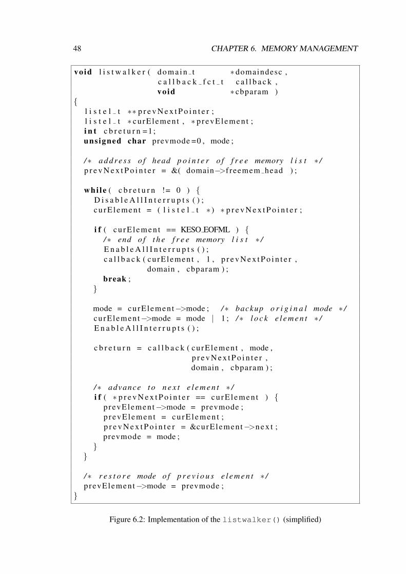
48 CHAPTER 6. MEMORY MANAGEMENT
void l i s t w a l k e r ( d o m a i n t ∗ domaindesc ,c a l l b a c k f c t t c a l l b a c k ,void ∗ cbparam )
{l i s t e l t ∗∗ p r e v N e x t P o i n t e r ;l i s t e l t ∗ curElement , ∗ prevE lemen t ;i n t c b r e t u r n =1;unsigned char prevmode =0 , mode ;
/∗ a d d r e s s o f head p o i n t e r o f f r e e memory l i s t ∗ /p r e v N e x t P o i n t e r = &( domain−>f reemem head ) ;
whi le ( c b r e t u r n != 0 ) {D i s a b l e A l l I n t e r r u p t s ( ) ;c u r E l e m e n t = ( l i s t e l t ∗ ) ∗ p r e v N e x t P o i n t e r ;
i f ( c u r E l e m e n t == KESO EOFML ) {/∗ end o f t h e f r e e memory l i s t ∗ /E n a b l e A l l I n t e r r u p t s ( ) ;c a l l b a c k ( curElement , 1 , p r e v N e x t P o i n t e r ,
domain , cbparam ) ;break ;
}
mode = curElement−>mode ; /∗ backup o r i g i n a l mode ∗ /curElement−>mode = mode | 1 ; /∗ l o c k e l e m e n t ∗ /E n a b l e A l l I n t e r r u p t s ( ) ;
c b r e t u r n = c a l l b a c k ( curElement , mode ,p r e v N e x t P o i n t e r ,domain , cbparam ) ;
/∗ advance t o n e x t e l e m e n t ∗ /i f ( ∗ p r e v N e x t P o i n t e r == c u r E l e m e n t ) {
prevElement−>mode = prevmode ;p revE lemen t = c u r E l e m e n t ;p r e v N e x t P o i n t e r = &curElement−>n e x t ;prevmode = mode ;
}}
/∗ r e s t o r e mode o f p r e v i o u s e l e m e n t ∗ /prevElement−>mode = prevmode ;
}
Figure 6.2: Implementation of the listwalker() (simplified)
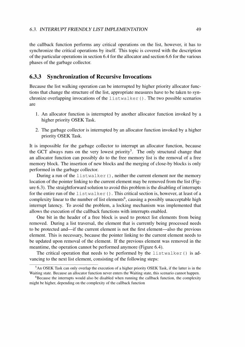
6.3. INTERRUPT FRIENDLY LIST IMPLEMENTATION 49
the callback function performs any critical operations on the list, however, it has tosynchronize the critical operations by itself. This topic is covered with the descriptionof the particular operations in section 6.4 for the allocator and section 6.6 for the variousphases of the garbage collector.
6.3.3 Synchronization of Recursive InvocationsBecause the list walking operation can be interrupted by higher priority allocator func-tions that change the structure of the list, appropriate measures have to be taken to syn-chronize overlapping invocations of the listwalker(). The two possible scenariosare
1. An allocator function is interrupted by another allocator function invoked by ahigher priority OSEK Task.
2. The garbage collector is interrupted by an allocator function invoked by a higherpriority OSEK Task.
It is impossible for the garbage collector to interrupt an allocator function, becausethe GCT always runs on the very lowest priority5. The only structural change thatan allocator function can possibly do to the free memory list is the removal of a freememory block. The insertion of new blocks and the merging of close-by blocks is onlyperformed in the garbage collector.
During a run of the listwalker(), neither the current element nor the memorylocation of the pointer linking to the current element may be removed from the list (Fig-ure 6.3). The straightforward solution to avoid this problem is the disabling of interruptsfor the entire run of the listwalker(). This critical section is, however, at least of acomplexity linear to the number of list elements6, causing a possibly unacceptable highinterrupt latency. To avoid the problem, a locking mechanism was implemented thatallows the execution of the callback functions with interrupts enabled.
One bit in the header of a free block is used to protect list elements from beingremoved. During a list traversal, the element that is currently being processed needsto be protected and—if the current element is not the first element—also the previouselement. This is necessary, because the pointer linking to the current element needs tobe updated upon removal of the element. If the previous element was removed in themeantime, the operation cannot be performed anymore (Figure 6.4).
The critical operation that needs to be performed by the listwalker() is ad-vancing to the next list element, consisting of the following steps:
5An OSEK Task can only overlap the execution of a higher priority OSEK Task, if the latter is in theWaiting state. Because an allocator function never enters the Waiting state, this scenario cannot happen.
6Because the interrupts would also be disabled when running the callback function, the complexitymight be higher, depending on the complexity of the callback function
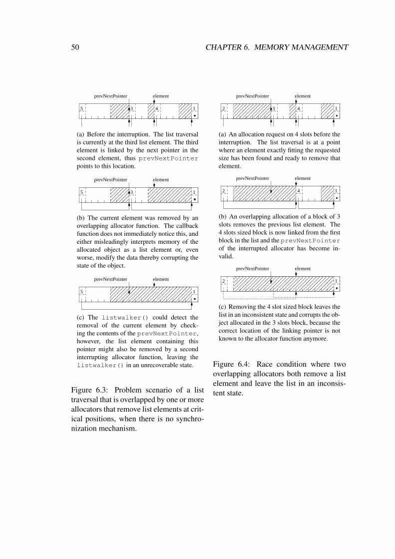
50 CHAPTER 6. MEMORY MANAGEMENT
������������
������������
����
����
��������
��������
5 13 4
prevNextPointer element
(a) Before the interruption. The list traversalis currently at the third list element. The thirdelement is linked by the next pointer in thesecond element, thus prevNextPointerpoints to this location.
������������
������������
����������������������������
����������������������������
5 13
prevNextPointer element
(b) The current element was removed by anoverlapping allocator function. The callbackfunction does not immediately notice this, andeither misleadingly interprets memory of theallocated object as a list element or, evenworse, modify the data thereby corrupting thestate of the object.
����������������������������������������������������
����������������������������������������������������
5 1
prevNextPointer element
(c) The listwalker() could detect theremoval of the current element by check-ing the contents of the prevNextPointer,however, the list element containing thispointer might also be removed by a secondinterrupting allocator function, leaving thelistwalker() in an unrecoverable state.
Figure 6.3: Problem scenario of a listtraversal that is overlapped by one or moreallocators that remove list elements at crit-ical positions, when there is no synchro-nization mechanism.
����
����
��������
��������
������������������������
������������������������
2 13 4
prevNextPointer element
(a) An allocation request on 4 slots before theinterruption. The list traversal is at a pointwhere an element exactly fitting the requestedsize has been found and ready to remove thatelement.
��������
��������
����������������������������������������
����������������������������������������
2 14
prevNextPointer element
(b) An overlapping allocation of a block of 3slots removes the previous list element. The4 slots sized block is now linked from the firstblock in the list and the prevNextPointerof the interrupted allocator has become in-valid.
����������������������������������������������������������������
����������������������������������������������������������������
2 1
prevNextPointer element
(c) Removing the 4 slot sized block leaves thelist in an inconsistent state and corrupts the ob-ject allocated in the 3 slots block, because thecorrect location of the linking pointer is notknown to the allocator function anymore.
Figure 6.4: Race condition where twooverlapping allocators both remove a listelement and leave the list in an inconsis-tent state.
6.4. ALLOCATOR FUNCTION 51
1. Read the next pointer of the current element.
2. Read and backup the locking mode of the next element.
3. Acquire a lock on the next element by setting the locking bit.
These steps need to be performed atomically, because
• An interrupting allocator between steps 1 and 2 might remove the following ele-ment. After removal of the element the assumed list element header now actuallycontains either the header of the object allocated in the removed block or a refer-ence field of that object. Reading the locking mode would be pointless and settingthe locking bit would corrupt the state of the object.
• The removal of the next element between steps 2 and 3 likewise corrupts theobject’s state when setting the locking bit. A special machine instruction such asbit-test-and-set would allow the atomic performance of steps 2 and 3 without theneed to disable interrupts, but is not available on the Tricore architecture7.
After acquiring the lock, the callback function is invoked, and upon return of the call-back function the lock on the previous element can be released.
6.4 Allocator FunctionThe design of KESO allows to choose a specific heap implementation on a per domainbase. Each heap implementation provides an allocator function of its own, but sincecode is shared among domains, a common entry point for allocating new objects needsto be available.
6.4.1 Generic Allocator Function InterfaceThe generic function for allocating new objects is the keso allocObject() func-tion. This function determines the size in bytes required by the new instance and invokesthe appropriate heap implementation specific allocator function. The allocation of in-stances of array classes works slightly different: For each array class type, a generic
7The initial approach was reserving a bit in the object header for the locking bit at the location corre-sponding to the locking bit in the header of a list element. This would allow the locking bit to be writteneven to an already allocated object without corrupting that object. This would, however, render the useof the bidirectional object layout impossible, because in case of objects that contain inner reference fieldsthe former header of the free list element would be occupied by such a reference field rather than theobject’s header. Additionally, the Tricore architecture does not provide an instruction for setting singlebits using an indirect addressing mode. One would therefore have to reserve an entire byte in the objectheader. This would clash with the goal of a minimal memory consumption.

52 CHAPTER 6. MEMORY MANAGEMENT
allocator function is provided that works similar to keso allocObject(). The dif-ferences are the calculation of the object size, that incorporates the length of the arrayand the byte size of each array element, and that the instance has an extra lengthfield in the object header. For the allocation of the required memory, the generic allo-cator functions for the array class types use the same heap specific allocator functionas the keso allocObject() function. In the following description of the interface,only the keso allocObject() function is described. The interface is illustratedin figure 6.5. The generic keso allocObject() function is invoked with the classidentifier (15) of the instance that is to be created. The required size in bytes (12 bytes)for the new instance is then determined from the class store using the provided classidentifier. The address of the heap specific allocator function is looked up in the do-main descriptor of the current domain, and the allocator function is then invoked withthe size in bytes of the memory needed for the instance. The heap specific allocatorfunction is expected to return a chunk of memory of a size larger than or equal to thesize requested, with every word except the first be cleared. If the heap specific allo-cator function fails to allocate a suitable chunk of memory, it is expected to throw anOutOfMemoryException. In the first byte of the memory chunk, the initial color(allocation color) of the object is passed. The generic keso allocObject() readsthe color byte, clears the first word of the memory chunk and initializes the headerof the object at the appropriate reference offset. The color byte is written as given bythe heap specific allocator function to the object header. The semantics of the colorbyte may differ for each heap implementation and are not known to the generic allocatorfunction.
6.4.2 IdleRoundRobin Allocator FunctionThe basic steps performed by the allocator function of the IRR heap are shown in fig-ure 6.5. First, the size in bytes (12 bytes) provided by the generic allocator functionis rounded up (16 bytes) to a multiple of the slot size (8 bytes) and converted to slots(2 slots). The listwalker() function is then invoked with an appropriate allocatorcallback function to find a suitable free block (see section 6.4.3). The found chunk ofmemory is cleared, except the first word, that contains the initial color byte of theobject or, if no suitable block is available, and OutOfMemoryException is thrown.Finally, the allocated chunk of memory is returned to the generic allocator function.
6.4.3 Allocation of a Memory BlockTo find a suitable block of free memory, the free memory list needs to be traversed. Thelistwalker() is used for this task and a callback function for allocating a suitableblock is provided. The callback function checks the size of each element it is invokedwith. The first element that has a size larger than or equal to the required size is then
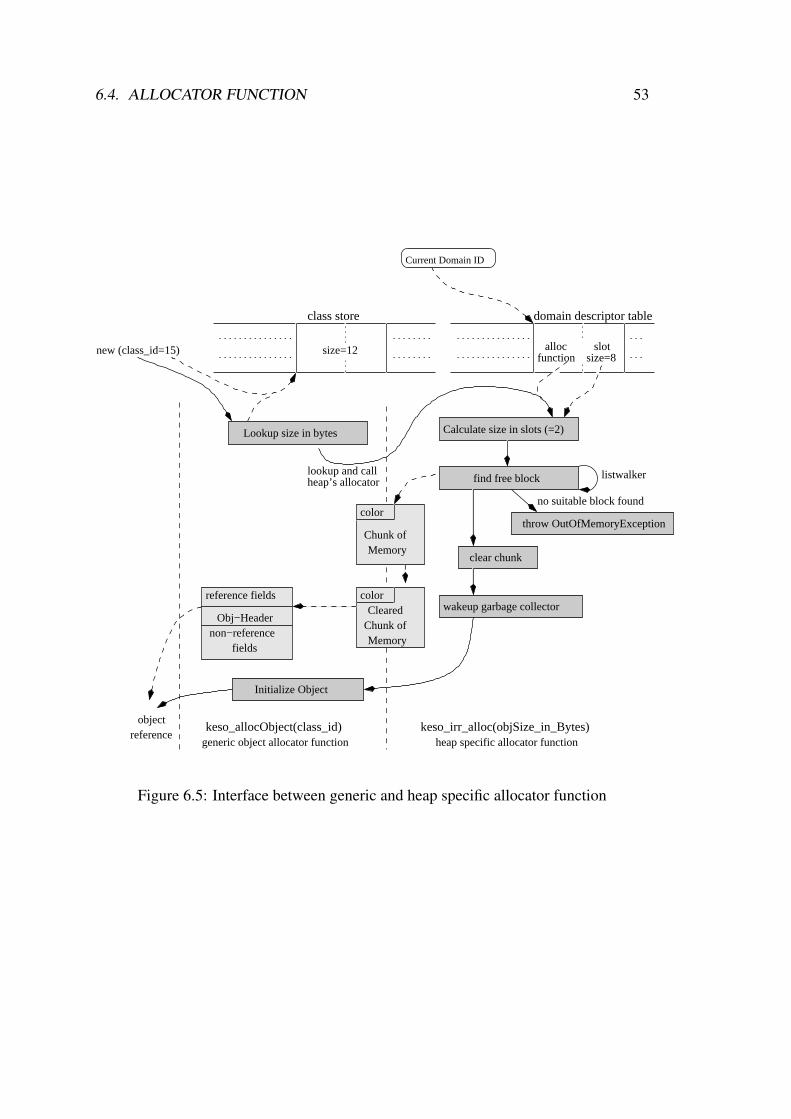
6.4. ALLOCATOR FUNCTION 53
size=12
class store
functionslotalloc
size=8
domain descriptor table
Current Domain ID
Lookup size in bytes
find free block
throw OutOfMemoryException
clear chunk
Chunk ofMemory
color
MemoryChunk ofCleared
colorwakeup garbage collector
Initialize Object
non−referenceObj−Header
fields
reference fields
Calculate size in slots (=2)
generic object allocator function heap specific allocator function
new (class_id=15)
lookup and call listwalker
no suitable block found
heap’s allocator
objectreference
keso_allocObject(class_id) keso_irr_alloc(objSize_in_Bytes)
Figure 6.5: Interface between generic and heap specific allocator function

54 CHAPTER 6. MEMORY MANAGEMENT
either downsized or, in case of an exact fit, removed, and the list traversal is terminated.The pointer to the allocated block is returned via the cbparam parameter to the callbackfunction, that contains the address of a pointer variable of the IRR heap’s allocatorfunction. If no suitable block is found, NULL is returned and the IRR heap’s allocatorfunction throws an OutOfMemoryException.
Checking the size of free memory block is not a critical operation, as it does onlyread the value from the list element. The downsizing and removal operations of a freeblock, however, are critical sections and need to be secured.
Downsizing of a free list element. When the callback function encounters a free blockwith a size larger than the required size, the following critical section is entered8:
1. Read the size of the free memory block again. It might have been downsizedafter checking the size but before disabling interrupts by a higher priorityallocator function.
2. Check if the size is still larger than the requested size. If it is not, leave thecritical section and continue with the check for an exactly fitting block.
3. Calculate the difference between the free memory block’s size and the re-quested size, which is the remaining size of the free memory block.
4. Write the remaining size to the list element.
The allocated memory is then available behind the downsized memory block,and its location can be calculated with the knowledge of the address of the freememory block and the remaining size of the free memory block, both of whichare available in local variables.
Removal of an exactly fitting element. When encountering a block of free memorymatching exactly the required size, the free memory block can be entirely allo-cated and removed from the free memory list, provided that the element was notlocked. If the element was locked by a lower priority Task, it has to be ignored. Incase the element was not locked before, the following critical section is entered:
1. Read the size of the block again. Although the element is protected frombeing removed it might have been downsized by a higher priority allocatorfunction.
2. If the size still matches, read the value of the next pointer of the current listelement, or else leave the critical section and continue.
8A compare-and-swap or similar instruction would allow the atomic execution of these steps, but isnot available on the Tricore architecture.

6.5. THE GARBAGE COLLECTOR OF THE IRR HEAP 55
3. Store the read next pointer in the pointer linking to the current element,pointed to by prevNextPointer, effectively removing the current ele-ment from the free memory list.
The removed free memory block can now entirely be used to store the new object.Steps 2 and 3 need to be performed atomically, because the next list element couldbe removed from the list, thereby updating the next pointer of the current listelement. Storing the previously read value in the linking pointer would then linkto memory block that has been removed from the free memory list and therebycorrupt the list.
The listwalker() function detects the removal of the element, because thevalue of the linking pointer was updated, and does not modify the allocated mem-ory attempting to restore the original locking mode.
Allocation Color
The initial color of the object needs to be passed in the color byte to the generic allo-cator function in the first byte of the allocated memory. Objects are generally allocatedwhite, except when the garbage collector is currently active in the domain. The transi-tion from white to black allocation happens per list element (see section 6.6.2), thus thecolor needs to be stored with each list element. Therefore, to pass the initial color of theobject in the first byte of the memory, the value only needs to be copied from the listelement header of the free memory block that the object was allocated from.
6.5 The Garbage Collector of the IRR HeapThe garbage collection is performed by a single lowest priority garbage collector OSEKTask. This Task manages the heaps of all domains that deploy the IRR heap imple-mentation as their heap type. Whenever the garbage collector starts a cycle in a spe-cific domain, the GCT migrates to this domain. This is done by changing the domainid of the associated KESO Task object, that is then set as the current domain by thePreTaskHook() whenever the GCT is scheduled. This is necessary for any userapplication code (e.g. the finalize() methods of reclaimed objects) to run in theproper domain environment.
6.6 Phases of the IRR Garbage CollectorA garbage collection cycle can be divided into several phases. As a mark-and-sweepgarbage collector, the IRR garbage collector goes through a scan-and-mark phase, in

56 CHAPTER 6. MEMORY MANAGEMENT
����
����
��������
��������
����������������������������
����������������������������
������������
������������
5 13 4
reachable objects
(a) Heap with reachable and unreachable objects before the Garbage Collection
0 0 0 0 0 0 0 0 0 0 0 0 0 0 0 00 0 0 00 0 0 0 0 0
(b) Initial cleared bitmap, every bit associated with one slot of the heap
1 1 1 1 0 0 0 1 1 1 0 1 1 1 1 10 0 0 01 0 0 0 0 0
(c) Bitmap after marking the slots associated with free memory blocks
1 1 1 1 0 1 1 1 1 0 1 1 1 1 11 1 0 11 1 1 1 1 01
(d) Bitmap after marking the slots occupied by reachable (living) objects
��������
��������
����
����
����
����
��������������������
��������������������
5 281 1
(e) Heap after the garbage collection cycle. The memory of unreachable objects was added tothe free memory list.
Figure 6.6: Sample Garbage Collection divided by phases

6.6. PHASES OF THE IRR GARBAGE COLLECTOR 57
that the reachable objects are scanned and colored, and a sweep phase, in which thememory of unreachable objects is reclaimed and added to the free memory list. Addi-tionally, as the IRR garbage collector manages multiple domains, there is an additionalinitial phase in which the domain for the garbage collection cycle is chosen, and becausethe garbage collector does not keep track of the total set of allocated objects, there is aphase in that the free memory is marked in the bitmap in order to distinguish it from thememory of unreachable objects in the sweep phase.
In the following, the different phases of the IRR garbage collector are described inthe order of processing in a garbage collector cycle. Figure 6.6 illustrates the impactsof each phase by means of a simple example.
6.6.1 Domain Selection
In the very beginning of the garbage collection cycle, the domain, whose heap will begarbage collected, has to be selected. Originally a simple Round Robin scheme wasused to select the domain, which has the disadvantage, that garbage collection is oftenperformed on domains that still have enough free memory, and no or only little garbagecan be collected, whereas other domains are running out of memory.
To avoid this problem, the Need of a domain for garbage collection is calculated as
Need = FreeSlots − NewSlotsAllocated − HeapSize
5
where FreeSlots is the total number of slots available in the free memory list, NewSlots-Allocated is the recorded number of slots allocated from the domain’s heap since thelast garbage collection cycle, and Heapsize is the total number of slots of the entireheap, 20% of which is additionally subtracted as a grace value. FreeSlots and NewSlots-Allocated are recorded in the domain descriptor of the domain and updated by the IRRallocator function and the IRR garbage collector. A domain is considered to require agarbage collection if a negative Need value is calculated for the domain.
The idea behind the Need function is that embedded systems typically run cyclicTasks that retain a similar allocation behavior during the runtime of the system. Thus,if there is still enough memory to allocate the number of slots since the last cycle plus adeviation of 20%, the domain likely has enough memory until the next cycle.
In order to keep a certain fairness, the selection of the domain is not solely basedon the Need value, and a Round Robin element is kept in the algorithm: All domainsmanaged by the IRR garbage collector are ordered in a circular buffer. The garbagecollector remembers the last processed domain across cycles. Starting from this domain,it searches through the circular buffer and selects the first domain with a negative Needvalue that is found, which is then selected for this cycle. In case there is no domain witha negative Need value at the time of the domain selection, the behavior of the garbage
58 CHAPTER 6. MEMORY MANAGEMENT
collector depends on its working mode, that is statically configured in the KESO systemconfiguration:
Lazy Mode (Default) In this mode, the garbage collector enters the Suspended state(TerminateTask()) and sets a global flag, indicating that the garbage collec-tor is sleeping. The IRR allocator function checks this flag upon each invocationand reactivates the garbage collector (ActivateTask()) if necessary.
This mode is the preferable in most scenarios and hence the default. First, it en-ables the OSEK operating system to put the microcontroller in a low power modewhen the system is idle. Second, a running garbage collector needs to disable in-terrupts at certain stages, which delays the reaction to external events. Putting thegarbage collector in the Suspended state allows immediate reaction to interruptswhen a garbage collection is not required (except if interrupts are blocked by theuser application). Third, write barriers (section 6.7.1) make certain types of writeaccesses to reference fields more expensive. When the garbage collector is notactive, the fastest path through a write barrier can be taken (figure 6.7).
Workaholic Mode In this mode, the garbage collector always chooses the domain withthe smallest Need value in the case that every domain has a positive Need value,therefore the garbage collector is always active.
The Round Robin element of the selection algorithm prevents one domain, that main-tains a large set of reachable objects using a large portion of the domain heap and there-fore keeps a low Need value, from starving other domains9.
6.6.2 Marking of Free Memory BlocksIn the second phase of the cycle, the free memory list is traversed one time and the bitsin the bitmap of the garbage collector, that are associated with slots of free memoryblocks, are set. This ensures, that after completing the scan phase, only the bits ofslots that belong to unreachable objects are still clear. After marking the bits of a freememory block, new objects allocated from that block cannot be reclaimed in the runningcycle anymore, and do not need to be scanned because of the active write barriers (seesection 6.7.1). When marking the slots of a free memory block, the allocation color fornew objects allocated from that block is changed to black at this point.
This phase is implemented as a callback function to the listwalker(), that per-forms the following operations for each block on the free memory list:
9If domains allocate a large set of objects in the startup phase and keep references to those objects,and do only allocate few objects in the regular runtime, the NewSlotsAllocated value is small after the firstcycle and the Need function computes a higher Need value, which additionally compensates the starvingeffects.
6.6. PHASES OF THE IRR GARBAGE COLLECTOR 59
1. Read the size of the list element
2. Change the allocation color in the list element header to black (after the cycle themeaning of the color is inverted and objects allocated in the meantime automati-cally become white)
3. Mark the bits in the bitmap corresponding to the block, using the previously readsize. The first corresponding slot can be calculated as
FirstSlotIndex(elementaddress) =elementaddress − heapstartaddress
slotsize
These steps do not need to be performed atomically, though it may happen, that anobject is allocated white between steps 1 and 2 and the bits associated with the slotsin the bitmap are marked in step 3. If the object is reachable during the scan phase, itwould unnecessarily be scanned and colored, and the bits in the bitmap would be markedagain, which causes some additional work, but does not impose any further problems.
The order of steps 1 and 2 is important, however. If the color would be changedbefore reading the size of the element, it could happen that an element is allocated blackafter changing the allocation color, but before reading the size of the free memory block.In this case, the bits in the bitmap corresponding to the slots of the object would not bemarked in step 3 and would neither be marked in the scan phase as the object is alreadycolored black. Therefore, it might happen that the object is reclaimed although it is stillreachable.
The bitmap modifications performed in this phase are illustrated in figure 6.6(b) tofigure 6.6(c), for the example scenario shown in figure 6.6(a).
6.6.3 Scan and Mark of Reachable Objects
In the scan-and-mark phase, the garbage collector scans, starting with a root set ofobjects, the reference fields of each discovered object, adds the referenced objects to theworking set, and marks the discovered objects, i.e. colors them and marks the slots usedby these objects in the bitmap. The root set consists of immortal system objects10, staticreference fields of the respective domain and the stacks of Tasks in the Waiting state.The CPU registers of the saved contexts of Tasks in the Waiting state do not need to bescanned, because every reference held in a CPU register is also stored in some referencefield in the memory.
10These are generally comprised by the object abstractions of the OSEK abstraction layer, i.e. Task,Alarm and Resource objects, however, Alarm and Resource objects do not contain any reference fieldsand no subclasses of these classes may be created. Therefore the set of immortal system objects that needto be scanned by the garbage collector is solely comprised by the Task objects.
60 CHAPTER 6. MEMORY MANAGEMENT
Overlapped execution of the scan-and-mark phase and the user applications imposescertain problems beyond the consistency of global data structures of the garbage collec-tor, and appropriate synchronization mechanisms need to be deployed. These problemsand the used techniques to solve these problems are described in section 6.7.
The working set of the garbage collector is maintained on the working stack ofobject references. Because an object reference is never added to the working set twicein a cycle, the maximum size of the working stack depends on the maximum numberof reachable objects in the system at a time, which is, in the worst case, the maximumnumber of objects that can be allocated from the heap plus the number of immortalobjects. The former is equal to the number of slots on the heap, the latter is fixed andknown at system creation time. This number could, however, be significantly reducedwith hints by the application developer.
Initially, the whole root set is pushed to the working stack. Pushing an object refer-ence, that is not a null reference, consists of the following steps:
1. Check if the object is already colored (if it is, do not push the reference)
2. Color the object by setting the color bit in the object header to the value thatcurrently represents black or gray color
3. Read the stack pointer
4. Increase the stack pointer by one
5. Write back the increased stack pointer
These operations are performed in the function pushObject() (figure 6.7), whichis also used by write barriers (see section 6.7.1). This critical section needs to be pro-tected by disabling interrupts. An overlapping pushObject() of the same reference,performed by a write barrier, between steps 1 and 2, can cause the object to be pushedon the stack multiple times. This is not tolerable as it might impact an overflow ofthe stack. Steps 3 through 5 need to be performed atomically, because an overlappingpushObject() between these steps would use the same stack slot, and the referencepushed by the overlapping write barrier would be overwritten and lost11.
The critical section above actually can be divided into two distinct critical sectionsbetween steps 2 and 3, but has been combined to avoid the doubled overhead for en-abling and disabling the interrupts in between12.
11In theory, pushObject() could overlap n times in this critical section, loosing n-1 pushed ref-erences, where n is the number of OSEK Tasks configured in the system (including the GCT) plus thenumber of ISRs plus the number of Alarm Callback routines.
12Steps 1 and 2 can be performed atomically on architectures with bit-test-and-set and bit-test-and-resetinstructions as available on 80386 architectures, steps 3 through 5 with a compare-and-swap or similarinstruction.
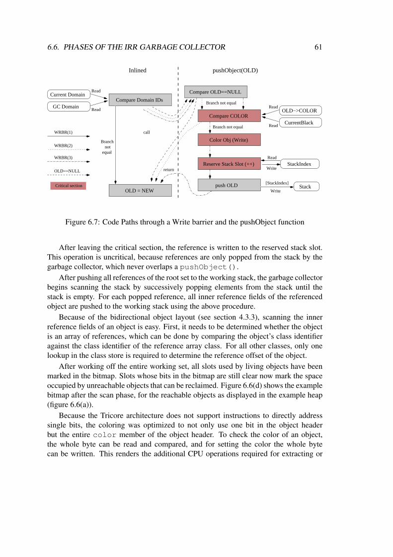
6.6. PHASES OF THE IRR GARBAGE COLLECTOR 61
WRBR(1)
WRBR(3)
WRBR(2)
OLD==NULL
OLD = NEW
Compare OLD==NULL
Compare COLOR
Color Obj (Write)
Read
Read
StackIndexReserve Stack Slot (++)
Stackpush OLDCritical section
Compare Domain IDs
Read
Read
GC Domain
Current Domain
Branchnot
equal
Inlined
Branch not equal
return
call
CurrentBlack
OLD−>COLOR
Read
Write
Branch not equal
[StackIndex]
Write
pushObject(OLD)
Figure 6.7: Code Paths through a Write barrier and the pushObject function
After leaving the critical section, the reference is written to the reserved stack slot.This operation is uncritical, because references are only popped from the stack by thegarbage collector, which never overlaps a pushObject().
After pushing all references of the root set to the working stack, the garbage collectorbegins scanning the stack by successively popping elements from the stack until thestack is empty. For each popped reference, all inner reference fields of the referencedobject are pushed to the working stack using the above procedure.
Because of the bidirectional object layout (see section 4.3.3), scanning the innerreference fields of an object is easy. First, it needs to be determined whether the objectis an array of references, which can be done by comparing the object’s class identifieragainst the class identifier of the reference array class. For all other classes, only onelookup in the class store is required to determine the reference offset of the object.
After working off the entire working set, all slots used by living objects have beenmarked in the bitmap. Slots whose bits in the bitmap are still clear now mark the spaceoccupied by unreachable objects that can be reclaimed. Figure 6.6(d) shows the examplebitmap after the scan phase, for the reachable objects as displayed in the example heap(figure 6.6(a)).
Because the Tricore architecture does not support instructions to directly addresssingle bits, the coloring was optimized to not only use one bit in the object headerbut the entire color member of the object header. To check the color of an object,the whole byte can be read and compared, and for setting the color the whole bytecan be written. This renders the additional CPU operations required for extracting or
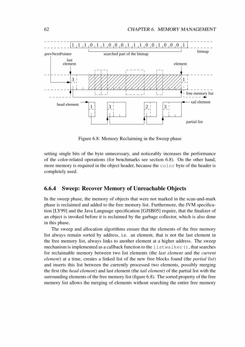
62 CHAPTER 6. MEMORY MANAGEMENT
13
1 3 32
1 1 1 11 1 1 11 0 0 0 0 0 0 0 0 0 1
������������������������������������������������������������
������������������������������������������������������������
elementelementlast
prevNextPointer searched part of the bitmapbitmap
free memory list
partial list
head elementtail element
Figure 6.8: Memory Reclaiming in the Sweep phase
setting single bits of the byte unnecessary, and noticeably increases the performanceof the color-related operations (for benchmarks see section 6.8). On the other hand,more memory is required in the object header, because the color byte of the header iscompletely used.
6.6.4 Sweep: Recover Memory of Unreachable Objects
In the sweep phase, the memory of objects that were not marked in the scan-and-markphase is reclaimed and added to the free memory list. Furthermore, the JVM specifica-tion [LY99] and the Java Language specification [GJSB05] require, that the finalizer ofan object is invoked before it is reclaimed by the garbage collector, which is also donein this phase.
The sweep and allocation algorithms ensure that the elements of the free memorylist always remain sorted by address, i.e. an element, that is not the last element inthe free memory list, always links to another element at a higher address. The sweepmechanism is implemented as a callback function to the listwalker(), that searchesfor reclaimable memory between two list elements (the last element and the currentelement) at a time, creates a linked list of the new free blocks found (the partial list)and inserts this list between the currently processed two elements, possibly mergingthe first (the head element) and last element (the tail element) of the partial list with thesurrounding elements of the free memory list (figure 6.8). The sorted property of the freememory list allows the merging of elements without searching the entire free memory

6.6. PHASES OF THE IRR GARBAGE COLLECTOR 63
list for candidates. Merging of reclaimed objects that occupied near-by slots happensautomatically as they appear as a sequence of cleared bits in the bitmap. Building thepartial list instead of inserting each discovered free block immediately into the freememory list is advantageous, because it does not need to be synchronized with the userapplication.
Because the listwalker() only passes the current element to the callback func-tion, the callback function must remember the last element it processed. The optionalparameter of the callback function cbparam is used for this purpose and contains apointer to a structure that contains the address of the last element as well as the currentposition in the bitmap. The pointer is initialized with NULL and the bitmap positionwith 0 before starting the listwalker(). The three possible invocation scenarios ofthe callback function are
• For the part of the heap before the first element, the last element pointer is NULLand the element pointer points to the first list element.
• For any part of the heap between two elements of the free memory list, the lastelement points to the last processed element and the element pointer points to thecurrent element.
• For the part of the heap after the last element, the last element pointer points to thelast element of the free memory list and the element pointer contains the specialvalue KESO EOFML.
Only the parts of the bitmap that correspond to the scanned part of the heap per invo-cation of the callback function need to be scanned, i.e. the parts corresponding to freememory blocks are skipped. The phase in which the free memory blocks are markedin the bitmap is nevertheless necessary because the size of a free memory block mighthave changed since the beginning of the cycle, or free memory blocks may have beenremoved from the list. These slots belong to objects that were allocated during thegarbage collector cycle and must not be freed during this cycle.
Before a new free memory block is inserted in the partial list, the finalizers of theunreachable objects contained within that block need to be invoked. Since the garbagecollector does not keep track of allocated objects, the object headers need to be foundwithin the free memory block. In front of the object header, there may be several refer-ence fields, depending on the class of the object. Because the least significant bit of theobject header is always set, it can be distinguished from references, which have theirleast significant bit cleared for alignment reasons13. When the object header is found,
13On 8-bit microcontrollers, this approach does not work and an alternate solution needs to be found.A possible solution would be aligning object headers on slot boundaries. A slot boundary is always at anaddress with a cleared least significant bit due to the minimum slot size of the heap.
64 CHAPTER 6. MEMORY MANAGEMENT
the finalizer of the object can be invoked. Afterwards, the non-reference fields of the ob-ject can easily be skipped as the class identifier can now be read from the object header,and be used to lookup the size of the object in the class store.
Synchronization with the User Applications
The insertion of the partial list in the free memory list needs to be synchronized withinterrupting allocator functions. Besides the case that there was no reclaimable mem-ory between the currently processed elements, there are four cases that are differentlyprocessed.
Neither head nor tail are mergeable If neither the head nor the tail of the partial listcan be merged with the surrounding elements of the free memory list, an un-critical insertion operation can be performed14. First, the next pointer of the tailelement of the partial list is assigned the address of the current element. Becausethe current element is locked by the listwalker(), it cannot be removed byan allocator and the reference stays valid. Afterwards, the address of the headelement of the partial list is stored in prevNextPointer. After the addresswas written back, the new elements are available to allocator functions in the freememory list. The current element needs to be unlocked by the callback function,except if the current element has the special value KESO EOFML.
Only head is mergeable If only the head element of the partial list is mergeable withthe last element, the next pointer of the tail element is assigned the address of thecurrent element, as above. The interrupts need to be disabled for the followingcritical section:
1. Check if the head is still mergeable with the last element (If not, proceed asif neither head nor tail were mergeable).
2. Add the size of the head element to the size of the last element.
All operations from checking if the elements are still mergeable until storing theincreased size must not be interrupted by an allocator, as downsizing of the lastelement would revoke the mergeable property. After the critical section, the nextpointer of the last element is updated with a local copy of the next pointer of thehead element, that was made before entering the critical section. This is not crit-ical, because the free memory list is in a consistent state where neither the lastnor the current element may be removed, and storing the next pointer is an atomic
14On architectures where a store operation for an address value needs to be split into two or more storeoperations, such as the AVR architecture, storing an address value is not an atomic operation and updatingthe next pointer needs to be included in the critical section.
6.6. PHASES OF THE IRR GARBAGE COLLECTOR 65
operation14. Therefore, the remainder of the partial list is simply not visible to al-locator functions until the store operation for the next pointer has been performed.The current element needs to be unlocked by the callback function, except if thecurrent element has the special value KESO EOFML.
Tail element mergeable (two cases). If the tail element is mergeable with the currentelement, this cannot be changed by interrupting allocators, because the currentelement must not be removed. A critical section is entered that performs:
1. Add the size of the current element to the size of the tail element
2. Copy the next pointer of the current element to the next pointer of the tailelement. The tail element and the current element have now been merged.
3. Check if the head element can be merged with the last element
• If the head element cannot be merged, store the address of the headelement in the linking location, pointed to by prevNextPointer.
• If the head element can be merged, add the size of the head elementto the size of the last element, and copy the next pointer of the headelement to the next pointer of the last element.
Finalize Issue
Before adding a new block to the partial list, the finalizers of all contained objects needto be invoked. Through the operations of the finalizer of an object, objects that werepreviously unreachable by the application may become reachable again, if they werereachable by the finalizable object (f-reachable), e.g. by writing a reference to an f-reachable object to a static reference field. The issue is discussed in detail in the JavaLanguage Specification [GJSB05]. In the simplest case, the finalizer can store the thisreference to a static reference field thereby making the object the finalizer is invoked onreachable again.
Basically, the Java specification requires an additional scan phase after calling thefinalizer that finds that the object is still unreachable. If the object becomes reachableagain, the application will work with an object that has already been finalized. If afinalized object is found to be unreachable again, the finalizer is not invoked again onthat object and it is reclaimed.
The IRR heap does currently not handle this issue. Instead, finalizers that make f-reachable objects reachable again are prohibited. This has the advantage that all objectsfound unreachable can immediately be reclaimed.
The downside is, however, that the distinction between f-reachable and reachableobjects might not always be obvious to the application developer. Therefore, as alternatesolutions, it is considered to either
66 CHAPTER 6. MEMORY MANAGEMENT
• not invoke the finalizers at all, which would violate the Java specification, or
• introduce a finalized state for objects, by using an additional bit in the objectheader. This is only necessary for class instances that override the default finalizer.On those instances, the finalize() method is invoked when an unfinalizedobject is found unreachable in the scan phase, the finalized bit is set but the objectis not reclaimed. If a finalized object or an object whose class does not overridethe default finalize() method is found unreachable, it is reclaimed. Thisadds the downside, that objects that override the finalize() method can at theearliest be freed in the second garbage collector cycle after becoming unreachable.
The finalizers are invoked by the GCT at the lowest priority, therefore they maybe interrupted by other Tasks. This behavior is conforming to the Java specificationthat allows finalizers the be executed in any thread and even the concurrent executionof multiple finalizers in different threads. The invocation of a finalize() methoddoes, however, prolongate the garbage collector cycle, which might impose problemsfor real-time systems, as it must be calculated by the application developer.
6.7 Interruptibility of the Scan PhaseDuring the scan phase of the garbage collection, the garbage collector can be interruptedby the user applications at any stage, with the exception of the short protected criticalsections. By overwriting reference fields, the user application (also called mutator inthis context) modifies the graph of reachable objects. If the mutator creates a newreference from a black object to a white object, this object is not discovered by thegarbage collector on this path during the scan phase anymore. This is not a problemif the object is still reachable via another discoverable path, which is the case in thebeginning of the garbage collector cycle. If the mutator removes the last discoverablepath to a living object, the object is not marked by the garbage collector and reclaimed.To avoid this problem, one of the following two conditions must be satisfied:
• a black reference field must never reference a white object
• the last discoverable path to a living, white object may never be removed
There are two different methods, that guarantee at least one of the two above conditions.Read barriers color white objects gray whenever the mutator reads a reference. Thus themutator never gets to see a white object, and therefore cannot create a path from a blackto a white object.
Write barriers, on the other hand, color objects upon write accesses. Different kindsof write barriers [GLS75, DLM+76, JL96] have been developed that differ in whichobject’s color is changed. Because write barriers commonly offer a better performance

6.7. INTERRUPTIBILITY OF THE SCAN PHASE 67
C
A
BCB
A
before after
Figure 6.9: Yuasa’s write barrier implementation
than read barriers, basically based on the assumption that read accesses occur more oftenthan write accesses, write barriers were used in KESO. A comparison of barrier meth-ods for garbage collection including overhead measurements is available in a technicalreport by B. Zorn [Zor90].
6.7.1 Write Barriers
For KESO, the write barrier variant of Yuasa [JL96] was chosen (figure 6.9). In thisimplementation, whenever a reference to a white object is overwritten, no matter if thereference field was already scanned or not, the object referenced by the overwrittenreference (B) is colored gray. This guarantees the second of the above conditions, as itprevents the last discoverable path to a living white object from being removed. Writebarriers are enabled before starting the phase where the free memory blocks are markedin the bitmap.
Write barriers add a significant amount of overhead to write accesses on referencefields. In order to keep write accesses to local reference variables of a Java method asfast as possible, write barriers are not used on local variables. Write barriers are enabledfor write accesses to static reference fields, reference fields in object instances and fieldwrites in an array of object references. All objects, that were reachable at this point,are not reclaimed in the same garbage collection cycle, because the write barrier marksthem, except if the object was only referenced on the stack of a waiting Task and thisreference is removed, in which case the object can safely be reclaimed.
6.7.2 Atomic Scanning of the Task Stacks
Because write barriers are not active on the local reference variables of Java methods,the Tasks’ stacks must be scanned atomically. Only stacks of Tasks in the Waiting stateneed to be scanned, the stacks of all other Tasks in the Suspended state are empty at the
68 CHAPTER 6. MEMORY MANAGEMENT
time the garbage collector starts.Scanning a stack is of a complexity linear to the size of the stack. In most cases,
the size of the stack of a Task is easily predictable at the time the stack is scanned bythe garbage collector, because the stack is only scanned when a Task is waiting for anEvent, which is only the case in few well-known places where WaitEvent() is called.Recursive invocation of blocking methods may, however, complicate the prediction ofthe stack size.
The straight-forward solution of disabling the interrupts for the entire scan of thestacks imposes a high interrupt latency, that depends on the size of the stacks which inturn depends on the user application, and would foil the low interrupt latency achievedby the aggressively optimized critical sections in the other parts of the garbage collector.However, it is not required to scan all Tasks atomically, but only the stack of one Taskat once15, and only the Task whose stack is scanned actually needs to be delayed untilthe scan operation is finished. Stefan Gabriel solved a similar problem in his studythesis [Gab05] when implementing a real-time garbage collector for the JX operatingsystem [GFWK02]. In his implementation, he completely disabled the scheduling tocreate copies of each stack. These copies could then be scanned without additionalsynchronization. This allows the processing of first level interrupt handlers while astack is copied.
Copying the stacks is not an attractive solution for KESO because of memory con-straints, furthermore the way KESO’s stacks are organized allows a very fast scanningof the stacks and an exact and fast detection of references on the stack, that is nearly ofthe same efforts as copying the stack16. When scanning a stack, all discovered objectsare merely colored gray, i.e. the reference is passed to pushObject(). The scanningof the objects themselves is performed after completing the stack scan.
Synchronization using OSEK Resources
The basic idea of Stefan Gabriel’s garbage collector was adapted for the IRR garbagecollector, however, the granularity was refined. Entirely disabling the scheduling stillposes the problem that high priority Tasks may be delayed by the garbage collection,even though the stack of those Tasks is not scanned. For the IRR heap, a synchronizationmechanism based on OSEK Resources was developed that allows a maximum flexibilityfor the granularity.
The basic idea is to assign a garbage collector resource (GCR) to each Task that usesthe WaitEvent() system service. These Tasks can be easily identified, because the
15The only problem one might think of is the propagation of a reference that is only held in a localreference variable on an unscanned (white) stack to an already scanned (black) stack. This is, however,only possible via a common object or static reference fields, and write barriers are active on both of these.
16In JX, reference fields on the stack need to be identified via a complex heuristic, which posed themajor reason for copying the stacks instead of immediately coloring the objects.
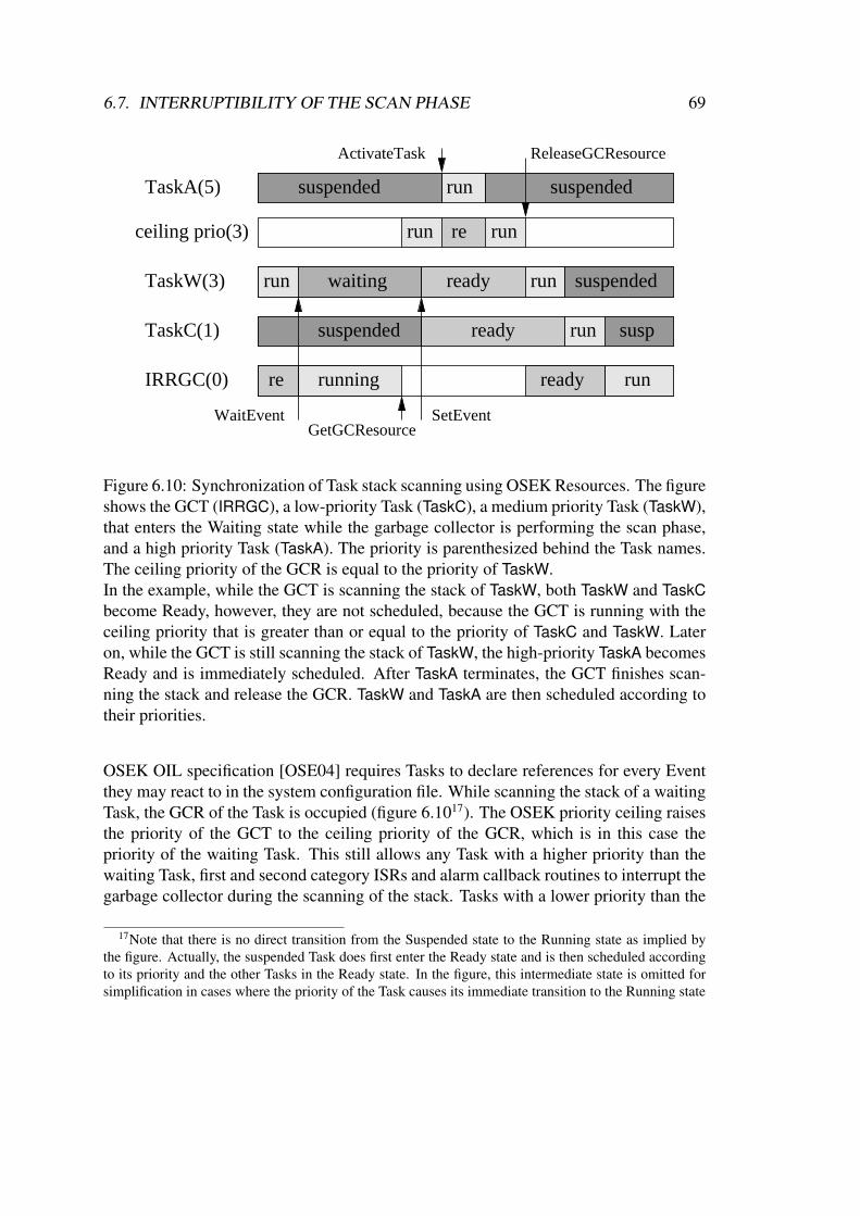
6.7. INTERRUPTIBILITY OF THE SCAN PHASE 69
run
run
run
run
re
re
suspended suspended
waiting ready run suspended
suspended ready run
runreadyrunning
susp
TaskA(5)
ceiling prio(3)
IRRGC(0)
TaskC(1)
ReleaseGCResourceActivateTask
TaskW(3)
WaitEventGetGCResource
SetEvent
Figure 6.10: Synchronization of Task stack scanning using OSEK Resources. The figureshows the GCT (IRRGC), a low-priority Task (TaskC), a medium priority Task (TaskW),that enters the Waiting state while the garbage collector is performing the scan phase,and a high priority Task (TaskA). The priority is parenthesized behind the Task names.The ceiling priority of the GCR is equal to the priority of TaskW.In the example, while the GCT is scanning the stack of TaskW, both TaskW and TaskCbecome Ready, however, they are not scheduled, because the GCT is running with theceiling priority that is greater than or equal to the priority of TaskC and TaskW. Lateron, while the GCT is still scanning the stack of TaskW, the high-priority TaskA becomesReady and is immediately scheduled. After TaskA terminates, the GCT finishes scan-ning the stack and release the GCR. TaskW and TaskA are then scheduled according totheir priorities.
OSEK OIL specification [OSE04] requires Tasks to declare references for every Eventthey may react to in the system configuration file. While scanning the stack of a waitingTask, the GCR of the Task is occupied (figure 6.1017). The OSEK priority ceiling raisesthe priority of the GCT to the ceiling priority of the GCR, which is in this case thepriority of the waiting Task. This still allows any Task with a higher priority than thewaiting Task, first and second category ISRs and alarm callback routines to interrupt thegarbage collector during the scanning of the stack. Tasks with a lower priority than the
17Note that there is no direct transition from the Suspended state to the Running state as implied bythe figure. Actually, the suspended Task does first enter the Ready state and is then scheduled accordingto its priority and the other Tasks in the Ready state. In the figure, this intermediate state is omitted forsimplification in cases where the priority of the Task causes its immediate transition to the Running state

70 CHAPTER 6. MEMORY MANAGEMENT
ceiling priority of the GCR are delayed, which is desired to avoid priority inversion.Creating a separate GCR for every extended Task that makes use of the Wait-
Event() system service is the finest granularity of the stack scanning synchronizationand allows a minimum number of Tasks being delayed by the operation. However, thisfinest granularity might not be required for every application scenario. Therefore, theIRRGC allows the definition of synchronization groups, that allow choosing coarsergranularities to save system resources. Every Task belonging to a domain using the IRRheap that uses the WaitEvent() system service is assigned a synchronization group,and a GCR is then created for each defined synchronization group and shared by allmembers of that group. The resulting ceiling priority of a GCR is determined by thehighest priority Task in the synchronization group. Locking this GCR therefore affectsa higher number of Tasks than a GCR chosen on a per-Task base. As an example, asynchronization group could be defined per domain.
6.7.3 Scan OrderIn the scan phase, it is imperative that the stacks of waiting Tasks are scanned beforescanning the remaining parts of the root set. Otherwise, the only reference to a whiteobject on a Task stack could, for instance, be written to a static reference field that wasalready scanned and removed from the stack. Since write barriers do only color theobject to that a reference is overwritten, they do not color the object in this case becausethe reference is overwritten on the stack where write barriers are not active.
6.8 BenchmarksThis section presents measurements of the overhead posed by the used write barriers aswell as comparisons of different implementation approaches.
All benchmarks are run on an Infineon TC1796b microcontroller, containing a 32-bitTricore v1.3 CPU clocked at 150 MHz during the test runs, 2 megabytes of embeddedflash memory, 192 kilobytes on-chip SRAM and a 16 kilobytes instruction cache. Themicrocontroller is attached to a Lauterbach hardware debugger, and the measured runtimes were recorded by the debugger.
KESO is under fast-paced development, and changes to the KESO code will likelyaffect the runtime of the tests. The tests that show the benefits of write barrier inliningand the coloring optimization were made with revision 357, all other tests with revision390 of the KESO subversion repository, and the test results should be reproducible withthat revision.
For each of the three types (static reference fields, object instance reference fields,components of an array of references) of write barrier protected field writes, a test pro-gram was written, that performs 20,000 consecutive writes of the respective field type.
6.8. BENCHMARKS 71
To determine the loop overhead of each test, the actual field writes were removed fromeach test and the time was measured. In all shown numbers, the loop overhead is alreadysubtracted. The shown values thus represent the actual time required for the 20,000 ref-erence writes of the respective type.
The overhead posed by a write barrier depends on the actual reference that is pushed.The three possible code paths through a write barrier where a non-null reference
is overwritten are illustrated in figure 6.7. Each test was performed for all three codepaths. To force the write barrier to take a specific path through the write barrier duringthe benchmark, the garbage collector was modified. The modifications for each codepath are as follows.
Without Write barriers (Without WRBR) Instead of passing through the write bar-rier, only the actual write access to the field was left in the code. This is exactlythe same code as it would be used without write barriers.
Write barriers not active (WRBR(1)) To model the path where the GCT is not per-forming a scan phase in the domain of the test Task, the GC domain was set to afixed value that differs from the test Task’s domain. Thus, the WRBR(1) path isalways taken.
Write barriers active, reference to a colored object overwritten (WRBR(2)) TheGC domain is set to a fixed value of the test Task’s domain. Furthermore thecondition of the test, that checks if the object is already colored, is inverted. Thecomparison then indicates that the object is already colored and never colors theobject.
Write barriers active, reference to a white object overwritten (WRBR(3)) The GCdomain is set to a fixed value of the test Task’s domain. The function push-Object() is modified to always color the referenced object white, effectivelydisabling the coloring of the object. Therefore, the WRBR(3) code path is alwaystaken, but instead of coloring the object gray it is always recolored white.
6.8.1 Overhead MeasurementsThe three tests were run with coloring optimization and inlined write barriers, and com-pared with the reference time without write barriers. The displayed times are the ab-solute measured run times of the functions minus the loop overhead. Null referencechecks for instance reference writes and null reference and array boundary checks forreference array component writes are not considered loop overhead and included in theprinted numbers.
Write access to an instance reference field without write barriers is the fastest ofthe three test types. Before accessing the field the reference only needs to be checked
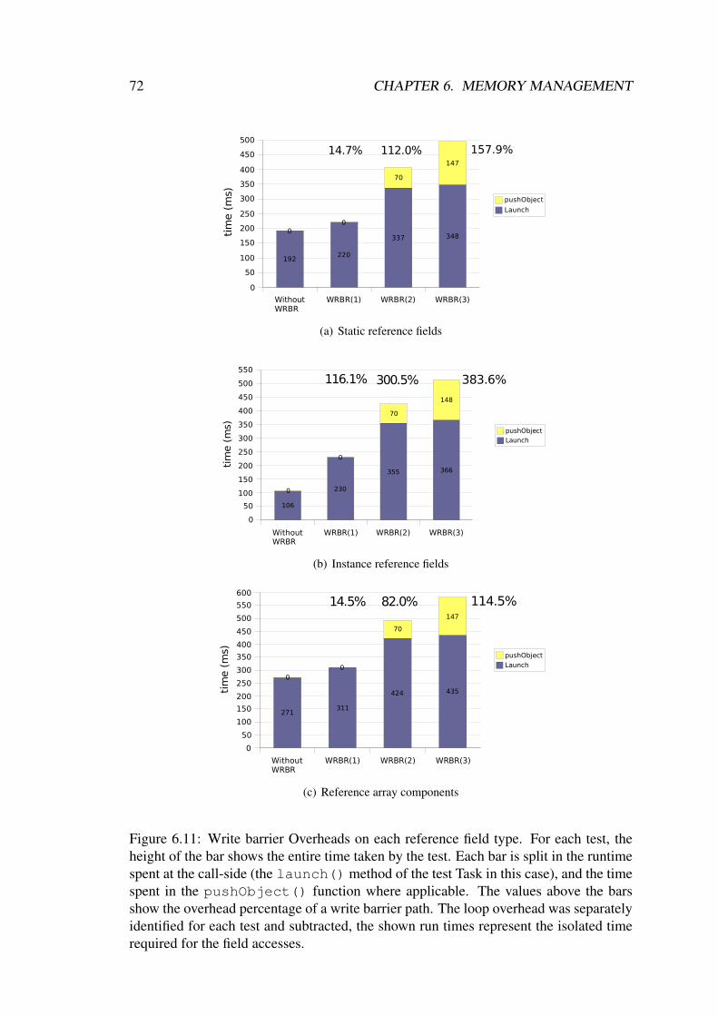
72 CHAPTER 6. MEMORY MANAGEMENT
Without WRBR
WRBR(1) WRBR(2) WRBR(3)
0
50
100
150
200
250
300
350
400
450
500
192220
337 3480
0
70
147
157.9%
pushObject
Launch
14.7% 112.0%
tim
e (
ms)
(a) Static reference fields
Without WRBR
WRBR(1) WRBR(2) WRBR(3)
0
50
100
150
200
250
300
350
400
450
500
550
106
230
355 366
0
0
70
148
383.6%
pushObject
Launch
116.1% 300.5%
tim
e (
ms)
(b) Instance reference fields
Without WRBR
WRBR(1) WRBR(2) WRBR(3)
0
50
100
150
200
250
300
350
400
450
500
550
600
271311
424 435
0
0
70
147
114.5%
pushObject
Launch
14.5% 82.0%
tim
e (
ms)
(c) Reference array components
Figure 6.11: Write barrier Overheads on each reference field type. For each test, theheight of the bar shows the entire time taken by the test. Each bar is split in the runtimespent at the call-side (the launch() method of the test Task in this case), and the timespent in the pushObject() function where applicable. The values above the barsshow the overhead percentage of a write barrier path. The loop overhead was separatelyidentified for each test and subtracted, the shown run times represent the isolated timerequired for the field accesses.
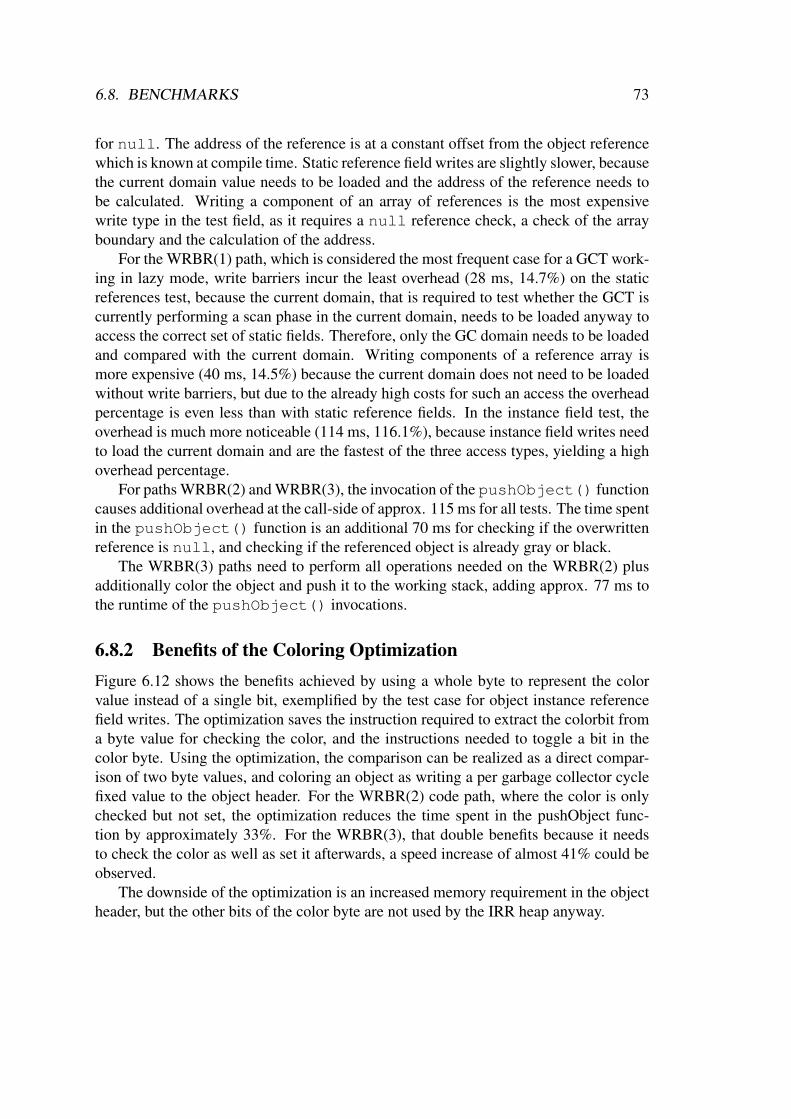
6.8. BENCHMARKS 73
for null. The address of the reference is at a constant offset from the object referencewhich is known at compile time. Static reference field writes are slightly slower, becausethe current domain value needs to be loaded and the address of the reference needs tobe calculated. Writing a component of an array of references is the most expensivewrite type in the test field, as it requires a null reference check, a check of the arrayboundary and the calculation of the address.
For the WRBR(1) path, which is considered the most frequent case for a GCT work-ing in lazy mode, write barriers incur the least overhead (28 ms, 14.7%) on the staticreferences test, because the current domain, that is required to test whether the GCT iscurrently performing a scan phase in the current domain, needs to be loaded anyway toaccess the correct set of static fields. Therefore, only the GC domain needs to be loadedand compared with the current domain. Writing components of a reference array ismore expensive (40 ms, 14.5%) because the current domain does not need to be loadedwithout write barriers, but due to the already high costs for such an access the overheadpercentage is even less than with static reference fields. In the instance field test, theoverhead is much more noticeable (114 ms, 116.1%), because instance field writes needto load the current domain and are the fastest of the three access types, yielding a highoverhead percentage.
For paths WRBR(2) and WRBR(3), the invocation of the pushObject() functioncauses additional overhead at the call-side of approx. 115 ms for all tests. The time spentin the pushObject() function is an additional 70 ms for checking if the overwrittenreference is null, and checking if the referenced object is already gray or black.
The WRBR(3) paths need to perform all operations needed on the WRBR(2) plusadditionally color the object and push it to the working stack, adding approx. 77 ms tothe runtime of the pushObject() invocations.
6.8.2 Benefits of the Coloring OptimizationFigure 6.12 shows the benefits achieved by using a whole byte to represent the colorvalue instead of a single bit, exemplified by the test case for object instance referencefield writes. The optimization saves the instruction required to extract the colorbit froma byte value for checking the color, and the instructions needed to toggle a bit in thecolor byte. Using the optimization, the comparison can be realized as a direct compar-ison of two byte values, and coloring an object as writing a per garbage collector cyclefixed value to the object header. For the WRBR(2) code path, where the color is onlychecked but not set, the optimization reduces the time spent in the pushObject func-tion by approximately 33%. For the WRBR(3), that double benefits because it needsto check the color as well as set it afterwards, a speed increase of almost 41% could beobserved.
The downside of the optimization is an increased memory requirement in the objectheader, but the other bits of the color byte are not used by the IRR heap anyway.
74 CHAPTER 6. MEMORY MANAGEMENT
WRBR(2) Instance
WRBR(2) Instance opt
WRBR(3) Instance
WRBR(3) Instance opt
0
50
100
150
200
250
300
350
400
450
307
206
448
266
pushObjectti
me (
ms)
Figure 6.12: Benefits of the optimized coloring method. The test application for objectinstance reference fields was taken for illustration. Only paths WRBR(2) and WRBR(3)are relevant to this test, because WRBR(1) does not enter the pushObject function. Thebars show the time spent in the pushObject function during the test, on top of the barsthe exact measured times are printed.
6.8.3 Differences between inlined and not-inlined Write barriers
When implementing write barriers, an implementation decision had to be made amonginlining parts of the write barrier or alternatively providing a write barrier function per-forming all operations of the write barrier, including the actual write operation. A ded-icated function has the advantage that less code needs to be generated at the call-side.The inlined variant performs the comparison of the current domain and the GC domainand the actual write operation at the call-side, but still calls the pushObject() func-tion for all further operations of the write barrier (figure 6.7), which generates additionalcode at the call-side but does not require the overhead of a function call in most cases,when the garbage collector is currently not performing a scan phase on the domain. Thetest for static reference field writes has been performed with a dedicated write barrierfunction and compared with the run times with inlined write barriers (figure 6.13).
The comparison shows a speed increase of 37% for the codepath WRBR(1) wherethe pushObject() function does not need to be invoked. The time spent at the call-side to perform the comparison of the domain ids and the actual write operation forinlined barriers is less than the time spent at the call-side to invoke the write barrierfunction. For the other paths, the benefit percentage is less due to the additional opera-tions required on those paths, but still measurable.

6.8. BENCHMARKS 75
Without WRBR
WRBR(1) WRBR(1) inlined
WRBR(2) WRBR(2) inlined
WRBR(3) WRBR(3) inlined
0
100
200
300
400
500
600
700
800
192258 220 257
324257
3580
93
0
2010
214 0
0
0
0
168
203
262
346pushObjectIRR_WRBRLaunch
tim
e (m
s)
Figure 6.13: Comparison of inlined write barriers and dedicated write barrier function(IRR WRBR). The coloring optimization was activated for the test runs.
6.8.4 Runtime Spectrum of the pushObject() FunctionThe run times of the pushObject() function for the different paths have measuredfor each test and are shown in figure 6.14. As expected, the runtimes do not differ forthe different tests.

76 CHAPTER 6. MEMORY MANAGEMENT
Null Reference Overwritten
Grey/Black Object Overwritten
White Object Overwritten
00.5
1
1.52
2.53
3.54
4.55
5.5
66.5
77.5
0.24
3.51
7.37
0.24
3.51
7.38
0.24
3.51
7.37
object array
instance field
static field
tim
e (
µs)
Figure 6.14: Run times of the pushObject() function
Chapter 7
Conclusion and Future Work
In this thesis, the design and implementation of the OSEK abstraction layer and a heapimplementation, that provides automatic memory management, both core parts of theKESO system, were presented.
7.1 OSEK Abstraction Layer
The OSEK abstraction layer provides access to OSEK system services, whereby accessrestrictions guarantee, that the strong isolation of domains is retained. The access re-strictions are enforced on the Java language level through a name service, carrying onthe type-safety-based isolation concept.
Different aspects of the OSEK system have been analyzed to identify the possibleimpacts on the domain isolation. Object abstractions, implemented in the form of im-mortal system objects, have only been introduced where necessary to provide accesscontrol to system services. The overhead imposed by the system object abstractioncompared to the use of plain OSEK data types is therefore only introduced in placeswhere it was found useful and required.
System services that do not require system objects as parameters, e.g. all interrupt-related system services, have been implemented with zero overhead by replacing in-vocations of the respective Java methods at the call-side with immediate calls to thecorresponding OSEK services. The system services, that are subject to access controland therefore are passed system objects additionally contain wrapper code in the methodbody around the call of the respective OSEK service, including a null reference checkfor the system object. This adds the overhead of the wrapper code plus the call to theJava service method. The exact impact still needs to be evaluated. In some cases, e.g.for the ActiveTask() service, where the wrapper code mostly consists of the nullreference check, it might be better to replace the service call at the call-side, as the refer-ence possibly was already checked in the calling method and can thus be omitted. This
77

78 CHAPTER 7. CONCLUSION AND FUTURE WORK
would additionally save the code and time required for the method call, thus possiblycreating a win-win situation saving both, code size and CPU time.
The name service that provides the user application with system objects uses staticdata structures. A lookup is resolved to a large extent at compile time, preventing ex-pensive string comparisons at runtime and reducing a lookup to a single or double arraylookup. Only the runtime data structures of the name service, that are actually used bythe application are added to the generated KESO system.
7.2 IdleRoundRobin Heap ImplementationIn the second part of this thesis, a heap implementation was presented that providesautomatic memory management adapted for embedded systems. During the design ofthe IdleRoundRobin heap, real-time capabilities were kept in mind and the heap wasoptimized to provide a low latency in the reaction to external events. The task model ofthe underlying OSEK operating system was incorporated in the design of the garbagecollector, and a low priority scheduling of the garbage collector was chosen because theeffort needed to scan the root set is minimal at the idle time of the system.
To achieve the low interrupt latency, a fully preemptible garbage collector was im-plemented. The developed algorithms do only require the disabling of interrupts forshort critical sections of constant complexity. The worst-case interrupt latency is there-fore low and predictable.
Resources were used to synchronize the scanning of Task stacks with the applica-tions, which is not of constant complexity. This allows high priority Tasks to be sched-uled during the scanning of a stack. Priority inversion is prevented by the OSEK priorityceiling protocol that is used for OSEK Resources.
Many of the critical sections, that are currently protected by the disabling of in-terrupts, can be implemented using special instructions such as the compare-and-swapinstruction, on architectures where such or similar instructions are available.
The dynamic allocation of new objects is currently allowed for interrupt serviceroutines and alarm callback functions. In common practice, however, memory is notdynamically allocated from such functions. Therefore, as a reasonable constraint, thedynamic allocation of memory could be prohibited for functions on the interrupt level.This would allow to synchronize most of the critical sections, that are currently pro-tected by disabling the interrupts, by disabling the OSEK scheduler. This would evenfurther improve the reaction times to external events. Preliminary benchmarks haveshown, however, that the IdleRoundRobin garbage collector already has a very low im-pact on the interrupt latency.
The garbage collector of the IdleRoundRobin heap is not yet suitable for the useby applications that need to meet hard real-time constraints. It can, however, be usedfor non real-time parts of the system, while still allowing hard real-time Tasks in other
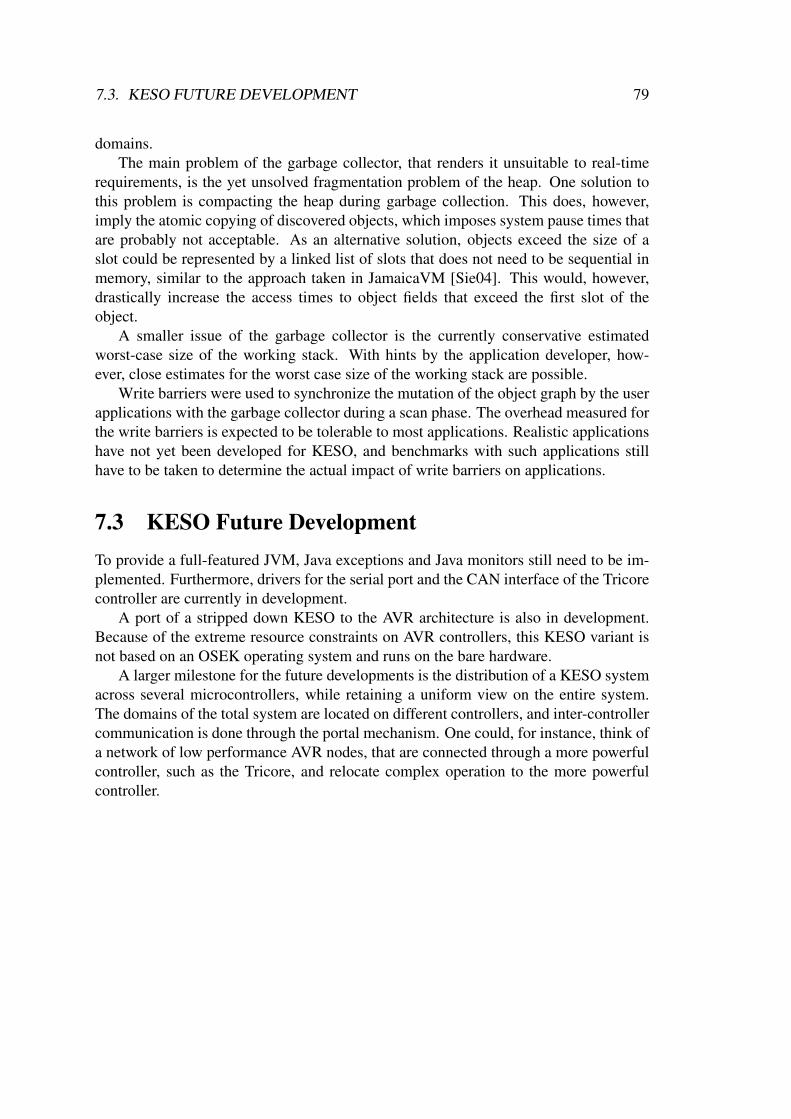
7.3. KESO FUTURE DEVELOPMENT 79
domains.The main problem of the garbage collector, that renders it unsuitable to real-time
requirements, is the yet unsolved fragmentation problem of the heap. One solution tothis problem is compacting the heap during garbage collection. This does, however,imply the atomic copying of discovered objects, which imposes system pause times thatare probably not acceptable. As an alternative solution, objects exceed the size of aslot could be represented by a linked list of slots that does not need to be sequential inmemory, similar to the approach taken in JamaicaVM [Sie04]. This would, however,drastically increase the access times to object fields that exceed the first slot of theobject.
A smaller issue of the garbage collector is the currently conservative estimatedworst-case size of the working stack. With hints by the application developer, how-ever, close estimates for the worst case size of the working stack are possible.
Write barriers were used to synchronize the mutation of the object graph by the userapplications with the garbage collector during a scan phase. The overhead measured forthe write barriers is expected to be tolerable to most applications. Realistic applicationshave not yet been developed for KESO, and benchmarks with such applications stillhave to be taken to determine the actual impact of write barriers on applications.
7.3 KESO Future DevelopmentTo provide a full-featured JVM, Java exceptions and Java monitors still need to be im-plemented. Furthermore, drivers for the serial port and the CAN interface of the Tricorecontroller are currently in development.
A port of a stripped down KESO to the AVR architecture is also in development.Because of the extreme resource constraints on AVR controllers, this KESO variant isnot based on an OSEK operating system and runs on the bare hardware.
A larger milestone for the future developments is the distribution of a KESO systemacross several microcontrollers, while retaining a uniform view on the entire system.The domains of the total system are located on different controllers, and inter-controllercommunication is done through the portal mechanism. One could, for instance, think ofa network of low performance AVR nodes, that are connected through a more powerfulcontroller, such as the Tricore, and relocate complex operation to the more powerfulcontroller.

80 CHAPTER 7. CONCLUSION AND FUTURE WORK
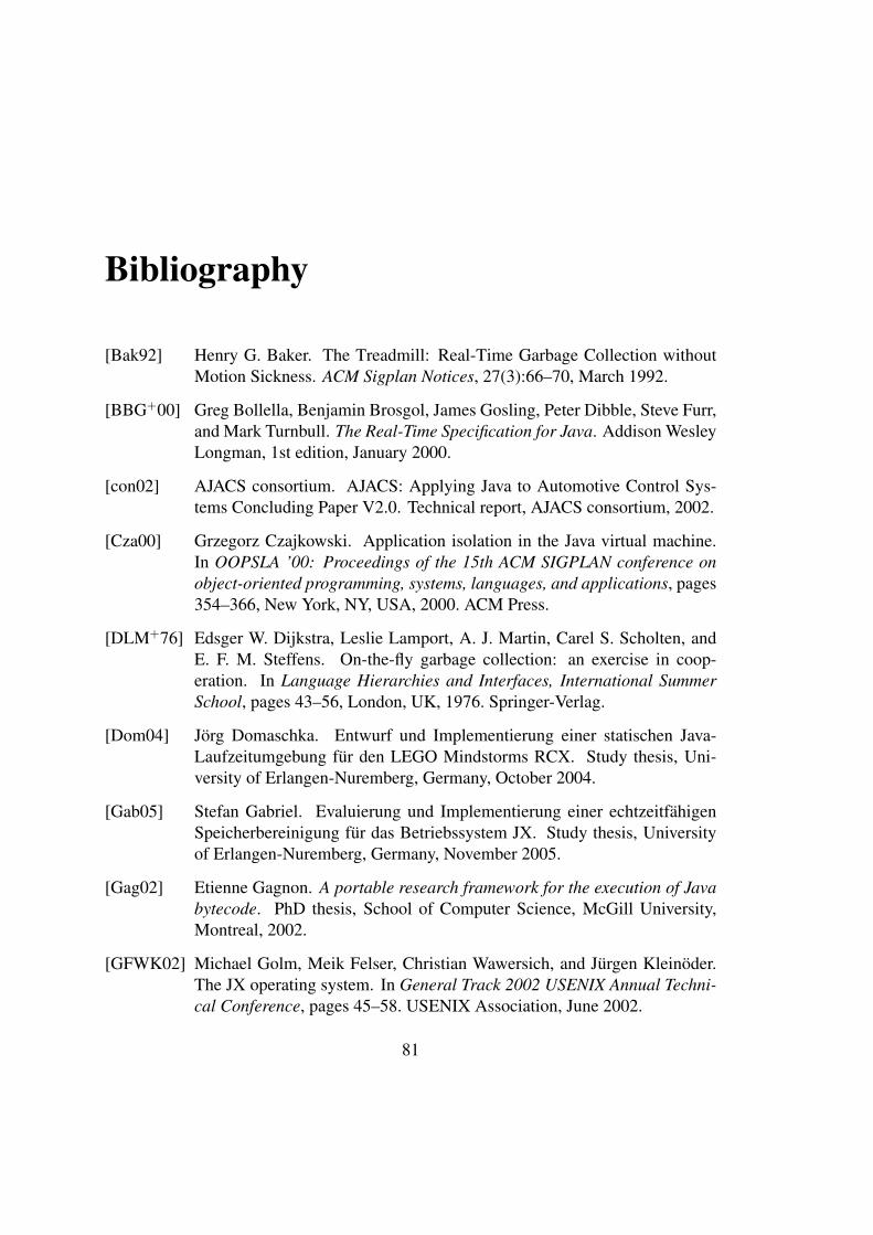
Bibliography
[Bak92] Henry G. Baker. The Treadmill: Real-Time Garbage Collection withoutMotion Sickness. ACM Sigplan Notices, 27(3):66–70, March 1992.
[BBG+00] Greg Bollella, Benjamin Brosgol, James Gosling, Peter Dibble, Steve Furr,and Mark Turnbull. The Real-Time Specification for Java. Addison WesleyLongman, 1st edition, January 2000.
[con02] AJACS consortium. AJACS: Applying Java to Automotive Control Sys-tems Concluding Paper V2.0. Technical report, AJACS consortium, 2002.
[Cza00] Grzegorz Czajkowski. Application isolation in the Java virtual machine.In OOPSLA ’00: Proceedings of the 15th ACM SIGPLAN conference onobject-oriented programming, systems, languages, and applications, pages354–366, New York, NY, USA, 2000. ACM Press.
[DLM+76] Edsger W. Dijkstra, Leslie Lamport, A. J. Martin, Carel S. Scholten, andE. F. M. Steffens. On-the-fly garbage collection: an exercise in coop-eration. In Language Hierarchies and Interfaces, International SummerSchool, pages 43–56, London, UK, 1976. Springer-Verlag.
[Dom04] Jorg Domaschka. Entwurf und Implementierung einer statischen Java-Laufzeitumgebung fur den LEGO Mindstorms RCX. Study thesis, Uni-versity of Erlangen-Nuremberg, Germany, October 2004.
[Gab05] Stefan Gabriel. Evaluierung und Implementierung einer echtzeitfahigenSpeicherbereinigung fur das Betriebssystem JX. Study thesis, Universityof Erlangen-Nuremberg, Germany, November 2005.
[Gag02] Etienne Gagnon. A portable research framework for the execution of Javabytecode. PhD thesis, School of Computer Science, McGill University,Montreal, 2002.
[GFWK02] Michael Golm, Meik Felser, Christian Wawersich, and Jurgen Kleinoder.The JX operating system. In General Track 2002 USENIX Annual Techni-cal Conference, pages 45–58. USENIX Association, June 2002.
81
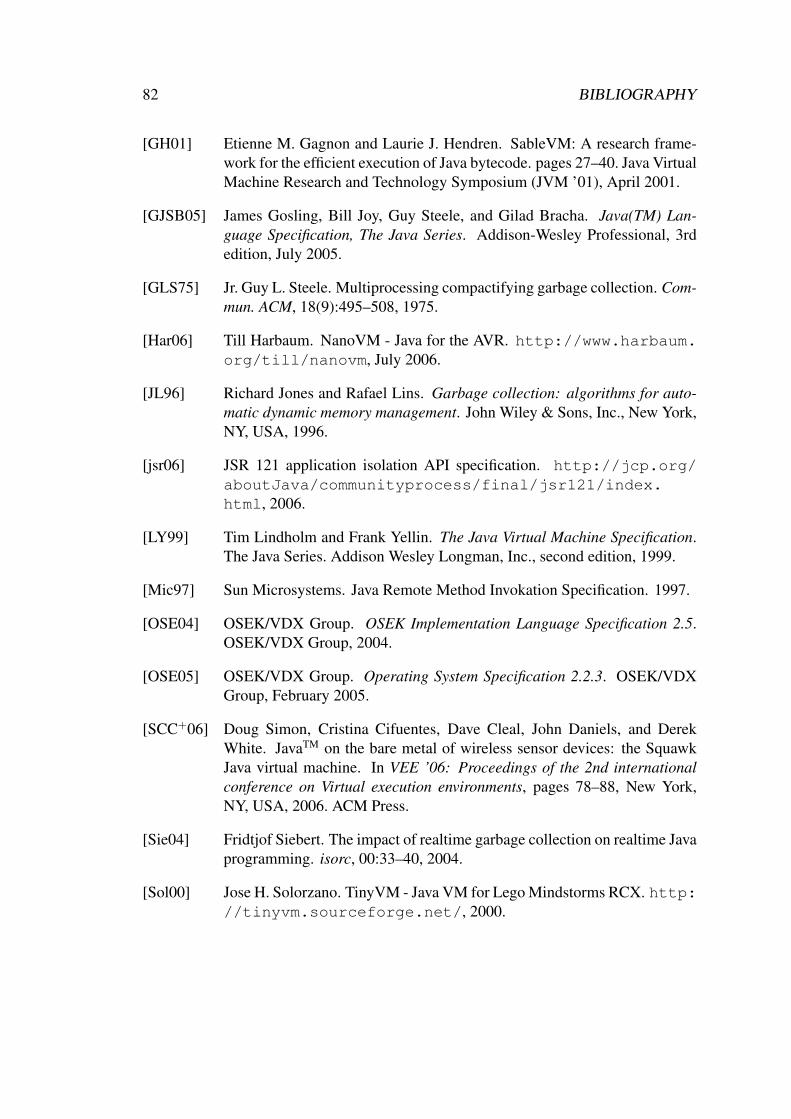
82 BIBLIOGRAPHY
[GH01] Etienne M. Gagnon and Laurie J. Hendren. SableVM: A research frame-work for the efficient execution of Java bytecode. pages 27–40. Java VirtualMachine Research and Technology Symposium (JVM ’01), April 2001.
[GJSB05] James Gosling, Bill Joy, Guy Steele, and Gilad Bracha. Java(TM) Lan-guage Specification, The Java Series. Addison-Wesley Professional, 3rdedition, July 2005.
[GLS75] Jr. Guy L. Steele. Multiprocessing compactifying garbage collection. Com-mun. ACM, 18(9):495–508, 1975.
[Har06] Till Harbaum. NanoVM - Java for the AVR. http://www.harbaum.org/till/nanovm, July 2006.
[JL96] Richard Jones and Rafael Lins. Garbage collection: algorithms for auto-matic dynamic memory management. John Wiley & Sons, Inc., New York,NY, USA, 1996.
[jsr06] JSR 121 application isolation API specification. http://jcp.org/aboutJava/communityprocess/final/jsr121/index.html, 2006.
[LY99] Tim Lindholm and Frank Yellin. The Java Virtual Machine Specification.The Java Series. Addison Wesley Longman, Inc., second edition, 1999.
[Mic97] Sun Microsystems. Java Remote Method Invokation Specification. 1997.
[OSE04] OSEK/VDX Group. OSEK Implementation Language Specification 2.5.OSEK/VDX Group, 2004.
[OSE05] OSEK/VDX Group. Operating System Specification 2.2.3. OSEK/VDXGroup, February 2005.
[SCC+06] Doug Simon, Cristina Cifuentes, Dave Cleal, John Daniels, and DerekWhite. JavaTM on the bare metal of wireless sensor devices: the SquawkJava virtual machine. In VEE ’06: Proceedings of the 2nd internationalconference on Virtual execution environments, pages 78–88, New York,NY, USA, 2006. ACM Press.
[Sie04] Fridtjof Siebert. The impact of realtime garbage collection on realtime Javaprogramming. isorc, 00:33–40, 2004.
[Sol00] Jose H. Solorzano. TinyVM - Java VM for Lego Mindstorms RCX. http://tinyvm.sourceforge.net/, 2000.

BIBLIOGRAPHY 83
[Sun04] Sun Microsystems. JSR-000139 Connected Limited Device Configuration1.1. http://www.jcp.org/aboutJava/communityprocess/final/jsr139/, 2004.
[Wil92] Paul R. Wilson. Uniprocessor garbage collection techniques. In Proc.Int. Workshop on Memory Management, number 637, Saint-Malo (France),1992. Springer-Verlag.
[Zor90] Benjamin Zorn. Barrier methods for garbage collection. Technical ReportCU-CS-494-90, University of Colorado, Boulder, Nov 1990.

84 BIBLIOGRAPHY
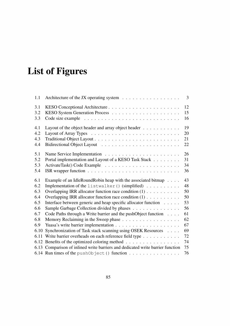
List of Figures
1.1 Architecture of the JX operating system . . . . . . . . . . . . . . . . . 3
3.1 KESO Conceptional Architecture . . . . . . . . . . . . . . . . . . . . . 123.2 KESO System Generation Process . . . . . . . . . . . . . . . . . . . . 153.3 Code size example . . . . . . . . . . . . . . . . . . . . . . . . . . . . 16
4.1 Layout of the object header and array object header . . . . . . . . . . . 194.2 Layout of Array Types . . . . . . . . . . . . . . . . . . . . . . . . . . 204.3 Traditional Object Layout . . . . . . . . . . . . . . . . . . . . . . . . . 214.4 Bidirectional Object Layout . . . . . . . . . . . . . . . . . . . . . . . 22
5.1 Name Service Implementation . . . . . . . . . . . . . . . . . . . . . . 265.2 Portal implementation and Layout of a KESO Task Stack . . . . . . . . 315.3 ActivateTask() Code Example . . . . . . . . . . . . . . . . . . . . . . 345.4 ISR wrapper function . . . . . . . . . . . . . . . . . . . . . . . . . . . 36
6.1 Example of an IdleRoundRobin heap with the associated bitmap . . . . 436.2 Implementation of the listwalker() (simplified) . . . . . . . . . . 486.3 Overlapping IRR allocator function race condition (1) . . . . . . . . . . 506.4 Overlapping IRR allocator function race condition (1) . . . . . . . . . . 506.5 Interface between generic and heap specific allocator function . . . . . 536.6 Sample Garbage Collection divided by phases . . . . . . . . . . . . . . 566.7 Code Paths through a Write barrier and the pushObject function . . . . 616.8 Memory Reclaiming in the Sweep phase . . . . . . . . . . . . . . . . . 626.9 Yuasa’s write barrier implementation . . . . . . . . . . . . . . . . . . . 676.10 Synchronization of Task stack scanning using OSEK Resources . . . . 696.11 Write barrier overheads on each reference field type . . . . . . . . . . . 726.12 Benefits of the optimized coloring method . . . . . . . . . . . . . . . . 746.13 Comparison of inlined write barriers and dedicated write barrier function 756.14 Run times of the pushObject() function . . . . . . . . . . . . . . . 76
85