an overview of denial of service issues and solutions in operators networkspaul_o/lafmi.pdf · ·...
TRANSCRIPT

1
"An overview of Denial of Service Issuesand Solutions in operators networks"
Olivier PaulGET/INT/LOR
08/31/20051a Escuela de Verano Franco-Mexicana de Telecomunicaciones

2
Acknowledgements
DDOSProject
HFRProject

3
Disclaimer
• This presentation is*not* meant to becomplete.

4
DoS Attacks definitions
Source DefinitionISO 7498-2 [ISO89] “The prevention of authorised access to
resources or the delaying of time of criticaloperations.”
NIST [Ols95] “Actions that prevent a network elementfrom functioning in accordance with itsintended purpose. Network elements may berendered partially or entirely unusable forlegitimate users. Denial of service maycause operations which depend ontimeliness to be delayed.”
CERT [CERT97] “A denial-of-service attack is characterisedby an explicit attempt by attackers toprevent legitimate users of a service fromusing that service”
IntroductionMitigationConclusion

5
Agenda
• Introduction– DoS attacks taxonomy
– Some figures.
• Existing DoS mitigation schemes– 4 main phases
– Mainly carriers/operator networks oriented
• Conclusion
IntroductionMitigationConclusion
6
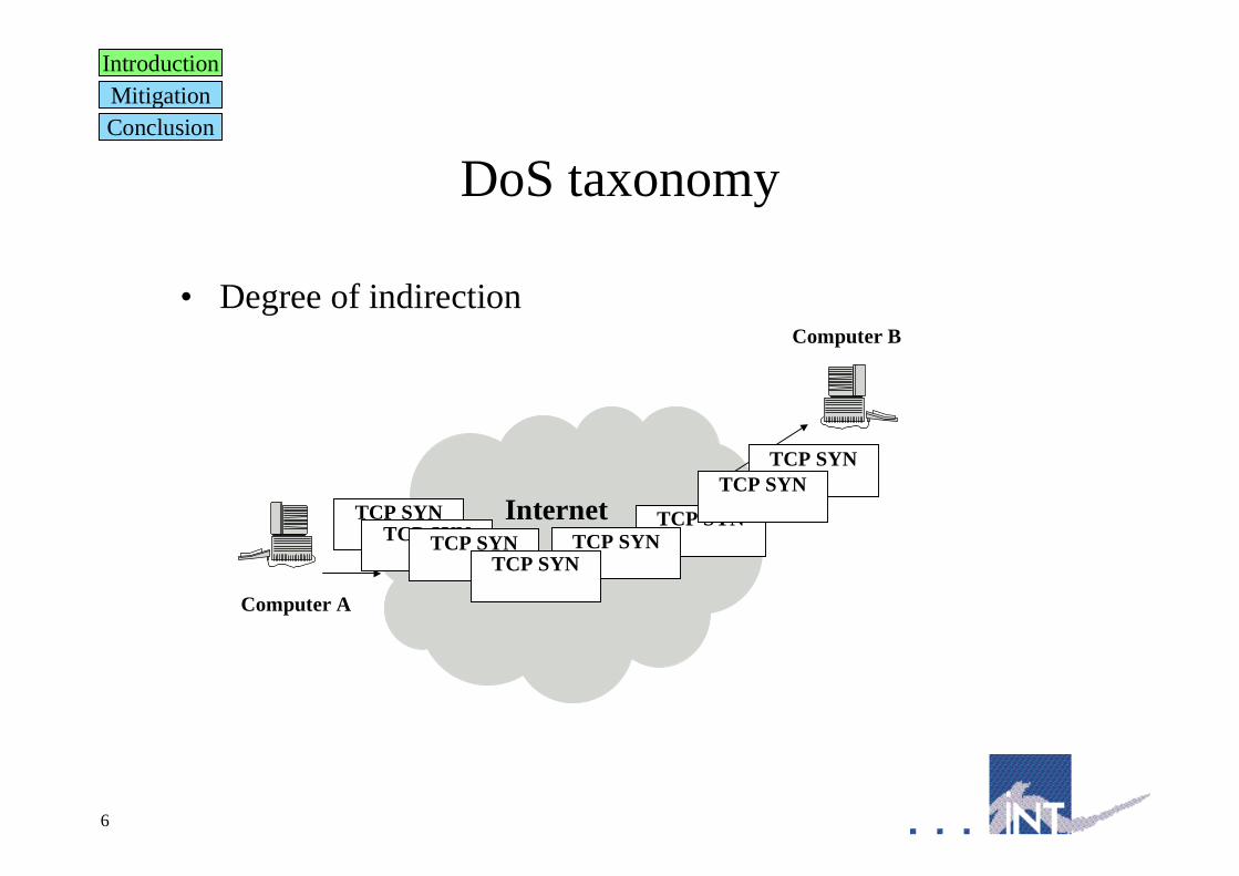
DoS taxonomy
• Degree of indirection
IntroductionMitigationConclusion
InternetTCP SYNTCP SYNTCP SYN
TCP SYNTCP SYN
TCP SYN
TCP SYNTCP SYN
Computer A
Computer B

7
DoS taxonomy
• Degree of indirection
IntroductionMitigationConclusion
Internet
Attack BAttack C
AttackerMaster
Slave A
Slave B
Slave C
Slave D
Victim B Victim C
Attack B
Attack B Attack C
Attack B

8
DoS taxonomy
• Degree of reflection
IntroductionMitigationConclusion
Internet
Source Address: CDest. Address : B
Attacker (A)Deflector (B)
Victim (C)
Source Address: BDest. Address: C
9
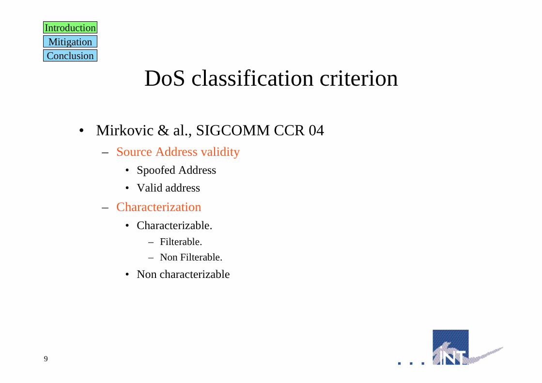
DoS classification criterion
• Mirkovic & al., SIGCOMM CCR 04– Source Address validity
• Spoofed Address
• Valid address
– Characterization
• Characterizable.– Filterable.
– Non Filterable.
• Non characterizable
IntroductionMitigationConclusion

10
DoS classification criterion
• Mirkovic & al., SIGCOMM CCR 04– Victim type
• Application
• Operating system
• Resource
• Network
– Exploited Vulnerability
• Semantic– Design level
– Implementation level
• Brute force
IntroductionMitigationConclusion
11
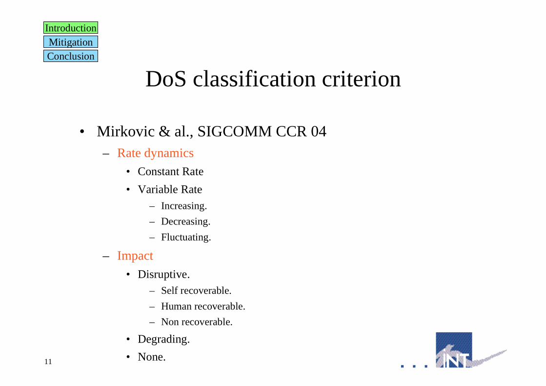
DoS classification criterion
• Mirkovic & al., SIGCOMM CCR 04– Rate dynamics
• Constant Rate
• Variable Rate– Increasing.
– Decreasing.
– Fluctuating.
– Impact
• Disruptive.– Self recoverable.
– Human recoverable.
– Non recoverable.
• Degrading.
• None.
IntroductionMitigationConclusion
12
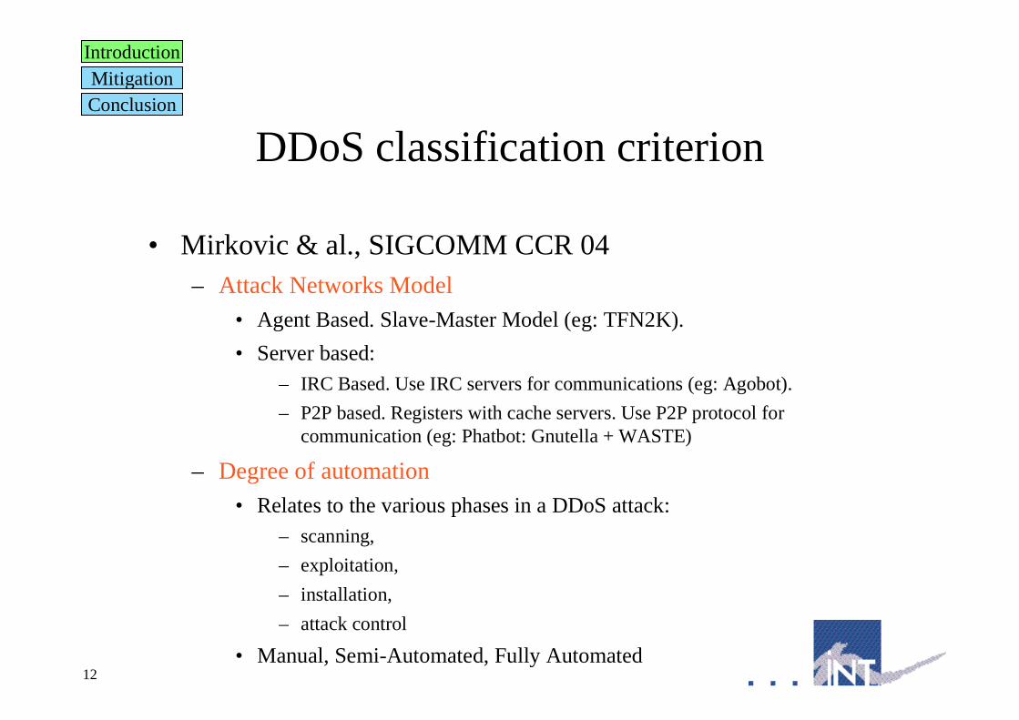
DDoS classification criterion
• Mirkovic & al., SIGCOMM CCR 04– Attack Networks Model
• Agent Based. Slave-Master Model (eg: TFN2K).
• Server based:– IRC Based. Use IRC servers for communications (eg: Agobot).
– P2P based. Registers with cache servers. Use P2P protocol forcommunication (eg: Phatbot: Gnutella + WASTE)
– Degree of automation
• Relates to the various phases in a DDoS attack:– scanning,
– exploitation,
– installation,
– attack control
• Manual, Semi-Automated, Fully Automated
IntroductionMitigationConclusion

13
DDoS Tools
• Usually integrate several types of attacks
• Example: TFN2K, Released in 1999.– Integrates:
• ICMP Flood, UDP Flood, TCP SYN Flood,
• SMURF. Use broadcast as address destination address and victim address assource.
• Targa3. Use uncommon IP packets to exploit vulnerabilities in protocolstacks.
• Able to send mixed attacks.
– Slave-Master Model
• Uses CAST-256 encryption between master and slaves.
• Communication using a protocol (UDP, ICMP, TCP) chosen randomly.
• Does not use acknowledgements.
IntroductionMitigationConclusion

14
Are there a lot of attacks ?
• Inferring DoS Attacks (Moore & al., USENIX 01)– Back-scatter analysis (Random destination address, no previous request)
– /8 network, one week monitoring.
• 13k attacks.
• Mostly TCP and ICMP.
• Duration from 1s to several days. 50% >10 minutes.
• 38% > 500 pps, highest 0.7M pps.
• Trends in DoS Attacks (Nazario, Usenix Security 03)– Back-scatter analysis, /8 routable, unused network, 1 month monitoring.
• 120k attacks.
• 2002: 75% TCP, 2003: 90% UDP.
• Duration from 1s to one day, 10% > 10 minutes.
• 2% > 100k packets, 0.5% > 1M packets.
IntroductionMitigationConclusion

15
An expending business ?
• From NANOG mailing List:Dat e: Thu, 3 Jun 2004 23: 32: 19 - 0700
Fr om: <NANOG Mai l i ng l i st >
Dear si r s.
We ar e gl ad t o you t o gi ve qual i t at i ve ser vi ce, on eliminationof sites. We can ki l l any si t e by our at t ack, whi ch have name' DDos attack’ <…>
The pr i ces at us ar e l ow, 60 dollars f or 6 hour s. 150 dol l ar s aday. Dest r oy any pr oj ect on t he I nt er net wi t h t he hel p ofour s DDos ser vi ce. Payment pr i ni maet sj a i n syst em WebMoney.
IntroductionMitigationConclusion
• Inferring DoS Attacks (Moore & al., USENIX 2001)– Individuals (13%).
– Infrastructure (7%).
– No particular geographical preferences.

16
An expending business ?
IntroductionMitigationConclusion
• Drone Armies Command and Control Centers.– June 2005 report (from Gadi Evron monthly report)
D om ain Count
SERV ER4Y OU - Server4Y ou Inc. 49
U NITEDCOL O-A S A utonomous Syste 44
SA GONET-TPA - Sago N etworks 80
M FNX M FN - M etromedia Fiber Ne 61
N OC - Network Operations Cente 39
A S13680 Hostway Corporation Ta 22
FDCSERV ERS - FDCservers.net L L 42
N EBRIX -CA - Nebrix Communicati 33
A SN-NA -M SG-01 - M anaged Soluti 31
L A M BDA NET-A S European Backbone 15
INFOL IN K -M IA -US - Infol ink Inf 28
L Y COS-EUROPE L ycos Europe GmbH 17
Note: Each C&C can command 100k+ slaves !
17
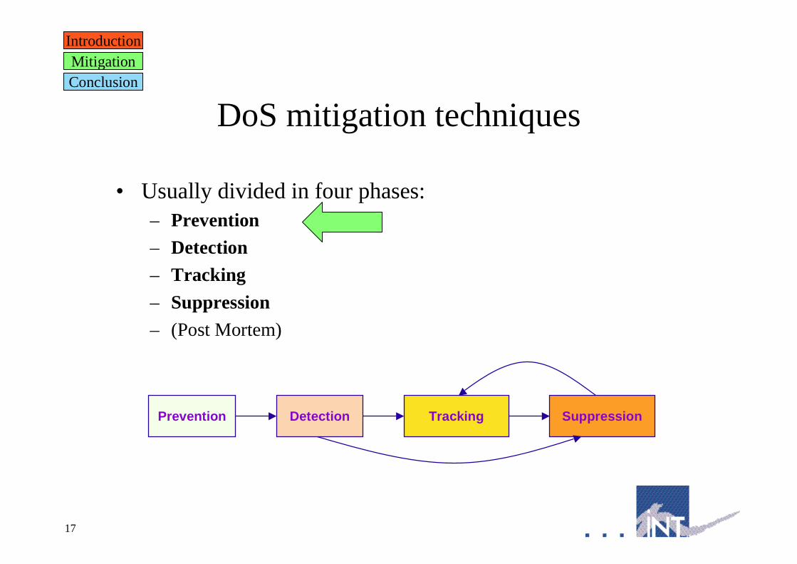
DoS mitigation techniques
• Usually divided in four phases:– Prevention
– Detection
– Tracking
– Suppression
– (Post Mortem)
IntroductionMitigationConclusion
DetectionPrevention SuppressionTracking

18
Prevention
• Customer side• Design more resilient protocols.
• Implement more resilient software.
• Protect end hosts (patching, anti virus, firewall).
• Public network side• Block well known protocol/ports/address ranges during outbreaks.
• Address spoofing prevention.– Ingress filtering/RPF.
– Hop count based filtering (Jin & al. CCS 2003).
– Source Address Validation (Li & al. INFOCOM 2002).
IntroductionMitigationConclusion
PreventionDetectionTracking
Suppression

19
Ingress Filtering
• IETF BCP 38• Restrict the scope of addresses that can be used by the attacker.
• Use ACL on routers.
IntroductionMitigationConclusion
PreventionDetectionTracking
Suppression
AttackerNetwork
R
Internet
Filter
Victim
User
C
B
A
F
I1
I2

20
Ingress Filtering
• IETF BCP 38• High in the network. Increase
spoofing ability.
• Low in the network. Increasemanagement burden.
• Some protocol need to useforeign address (e.g. Mobile IP)
• Some other protocols need to usespecial addresses (e.g. BOOTP)
• Some performance issues.
• Not widely implemented.
IntroductionMitigationConclusion
PreventionDetectionTracking
Suppression
AttackerNetwork
R
Internet
Filter
Victim
User
C
B
A
F
I1
I2

21
uRPF
• Unicast Reverse Path Forwarding• Or … how to use routers architecture smartly
Routing Processor
FIB FIB FIB FIB FIB FIB FIB FIB Line Cards
RouterRouting Processor
Juniper M160
Ports
Other routers
IntroductionMitigationConclusion
PreventionDetectionTracking
Suppression
RIB

22
uRPF
• Unicast Reverse Path Forwarding• Use FIB information to build filtering rules automatically.
• No rules at all, Just use the FIB !
• No performance issues.
IntroductionMitigationConclusion
PreventionDetectionTracking
Suppression
AttackerNetwork
R
Internet
Filter
Victim
User
C
B
A
F
I1
I2
Destination Outgoing InterfaceA I2R I1

23
Hop Count Filtering
• Jin & al. ACM CCS 2003:– Number of hops between end hosts should remain the same.
IntroductionMitigationConclusion
PreventionDetectionTracking
Suppression
AttackerNetwork
R
Internet
Filter
Victim
User
C
B
A
F
I1
I2
• For each packet ( SA, TTL)
– I nf er or i gi nal TTL’ f or sour ce SA.
– Comput e hop count HC = TTL’ - TTL.
– Ret r i eve st or ed hop count f orSA: HC[ SA] .
– HC ! = HC[ SA] f l ag packet asspoof ed.
TTL=255
TTL=243
TTL=255
TTL=238

24
Hop Count Filtering
• Jin & al. ACM CCS 2003:– Assumptions:
• Ability to infer original TTL.– Based on the fact that only a few original TTLs values exist in practice.
• Routes stability.
• Not all existing sources have the same hop count.
• Attacker– is not located close to the victim.
– is not able to know hop count between arbitrary hosts and victim.
– Implementation:• Use prefix based aggregation to limit size of HC[] table.
IntroductionMitigationConclusion
PreventionDetectionTracking
Suppression

25
DoS mitigation techniques
• Usually divided in four phases:– Prevention
– Detection
– Tracking
– Suppression
– (Post Mortem)
IntroductionMitigationConclusion
DetectionPrevention SuppressionTracking
PreventionDetectionTracking
Suppression

26
Detection Goals
• Decide whether an attack is going on.• Identify the traffic related to the attack.
– Generate a signature that will unambiguously identify the trafficgenerated by the attacker.
– This signature will later be used in other mitigation phases.
IntroductionMitigationConclusion
PreventionDetectionTracking
Suppression

27
Detection Taxonomy
• Detection Model• Detection Location• Detection Co-operation
– Standalone (Most existing techniques).
– Sharing information• Speed up/allow detection.
– Peng & al. (ACISP 03).
– Lakhina & al. (INFOCOM 04).
IntroductionMitigationConclusion
PreventionDetectionTracking
Suppression

28
Detection Taxonomy
• Detection location– Close to victim.
• Detection is easy but result comes too late.
– Close to attacker.• Because of distribution, attack events may be scarce.
– Intermediate networks.• Need to interact with existing devices.
• High speed processing.
IntroductionMitigationConclusion
PreventionDetectionTracking
Suppression

29
Detection Taxonomy
• Detection Model– Knowledge based
• Know what an attack looks like.
• Mainly applies to vulnerabilities oriented attacks– eg: Snort rule for malformed request DoS attack on REAL audio server:
alert tcp $EXTERNAL_NET any -> $HOME_NET 7070 (msg:"DOS Real AudioServer"; flow:to_server,established; content:"|FF F4 FF FD 06|";reference:arachnids,411; reference:bugtraq,1288;reference:cve,2000-0474; classtype:attempted-dos; sid:276; rev:5;)
• But also works for some poorly coded attack tools:– eg: Snort rule for shaft SYN Flooding attack:
alert tcp $HOME_NET any <> $EXTERNAL_NET any (msg:"DDOS shaftsynflood"; flow:stateless; flags:S,12; seq:674711609;reference:arachnids,253; reference:cve,2000-0138;classtype:attempted-dos; sid:241; rev:10;)
IntroductionMitigationConclusion
PreventionDetectionTracking
Suppression

30
Detection Taxonomy
• Detection Model– Knowledge based main challenges
• Obfuscation
• Speed:– Faster pattern matching algorithms (1Gb/s).
– FPGA based implementations (~5Gb/s).
• Signatures construction– Discover new attacks (Honeypots, Sinkholes, Network telescopes).
– Build new signatures rapidly and automatically.
» Network/Transport based methods (eg. Estan SIGCOMM 02)
» Application level (eg. Singh & al. OSDI 04, Kim & al. USENIX SEC 04)
» Implementation at UCSD ~200Mb/s.
IntroductionMitigationConclusion
PreventionDetectionTracking
Suppression

31
Detection Taxonomy
• Detection Model– Behaviour based
• Know how system usually behaves.
• Changes in behaviour can only be explained by attack.
– Behaviour based main challenges• Performance (depending on its location), Speed of detection.
• Adaptation to existing monitoring/network devices.
• Accuracy.
IntroductionMitigationConclusion
PreventionDetectionTracking
Suppression
32
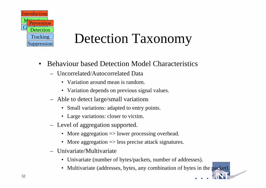
Detection Taxonomy
• Behaviour based Detection Model Characteristics– Uncorrelated/Autocorrelated Data
• Variation around mean is random.
• Variation depends on previous signal values.
– Able to detect large/small variations• Small variations: adapted to entry points.
• Large variations: closer to victim.
– Level of aggregation supported.• More aggregation => lower processing overhead.
• More aggregation => less precise attack signatures.
– Univariate/Multivariate• Univariate (number of bytes/packets, number of addresses).
• Multivariate (addresses, bytes, any combination of bytes in the packet).
IntroductionMitigationConclusion
PreventionDetectionTracking
Suppression

33
Intermediate networks
• Asymmetry monitoring (Gil & al. Usenix 01).– Basic idea:
• Normal operation yield fixed forward/backward traffic volume ratio.
• DDoS generate variations of this ratio.
IntroductionMitigationConclusion
PreventionDetectionTracking
Suppression
Requests received
Requests servedServer capacity
Uncorrelated Data
Univariate

34
Intermediate networks
• Asymmetry monitoring (Gil & al. Usenix 01).– Basic idea:
• It is not feasible nor effective to keep a state for each destination.
• Create a data structure that allows asymmetry to be kept.
IntroductionMitigationConclusion
PreventionDetectionTracking
Suppression
w.*.*.*
w.x.*.*
w.x.y.*
w.x.y.z
– Structure representsforward/backward ratio.
– Root stores ratio for /8 prefixes.
– If ratio for w/8 passes over a givenlevel we create a leaf zooming onw.x/16.
– If ratio for w.x/16 passes below agiven level we delete the w.x/16 leafand collapse the results in w/8.
– Structure size is limited.
Supports Aggregation
Large Variations

35
Intermediate networks
• Power Spectral Analysis (Cheng & al. GLOBECOM 02)– Basic idea:
• Well regulated TCP flows can be considered as legitimate.
• Keeping a state for each TCP flow is not feasible.
• Need to find this information per aggregate.
– Spectral Analysis.• Let’s consider a packet arrival process
– X(t) = number of packets received during [t-d;t], (d~10ms)
• We can evaluate periodicity of the packet arrival process using anautocorrelation function.
– R(l,t) = degree of correlation between signal at t and signal at t+l
– Maximise R(l,t)
IntroductionMitigationConclusion
PreventionDetectionTracking
Suppression
Supports Some Aggregation
Autocorrelated Data
Univariate

36
Intermediate networks
IntroductionMitigationConclusion
PreventionDetectionTracking
Suppression
• Why should we get some periodicity ?

37
-2
-1.5
-1
-0.5
0
0.5
1
1.5
2
-20 -15 -10 -5 0 5 10 15 20
Intermediate networks
• Power Spectral Analysis (Cheng & al. GLOBECOM 02)– Example (3 TCP flows, F1(p=3,s=0), F2(p=3,s=1), F3(p=1,s=0)):
IntroductionMitigationConclusion
PreventionDetectionTracking
Suppression
Poor correlation(low R(l1,t))
I1
0

38
-2
-1.5
-1
-0.5
0
0.5
1
1.5
2
-20 -15 -10 -5 0 5 10 15 20
Intermediate networks
• Power Spectral Analysis (Cheng & al. GLOBECOM 02)– Example (3 TCP flows, F1(p=3,s=0), F2(p=3,s=1), F3(p=1,s=0)):
IntroductionMitigationConclusion
PreventionDetectionTracking
Suppression
Some correlation(Average R(l2,t))
I2
0
39
-2
-1.5
-1
-0.5
0
0.5
1
1.5
2
-20 -15 -10 -5 0 5 10 15 20
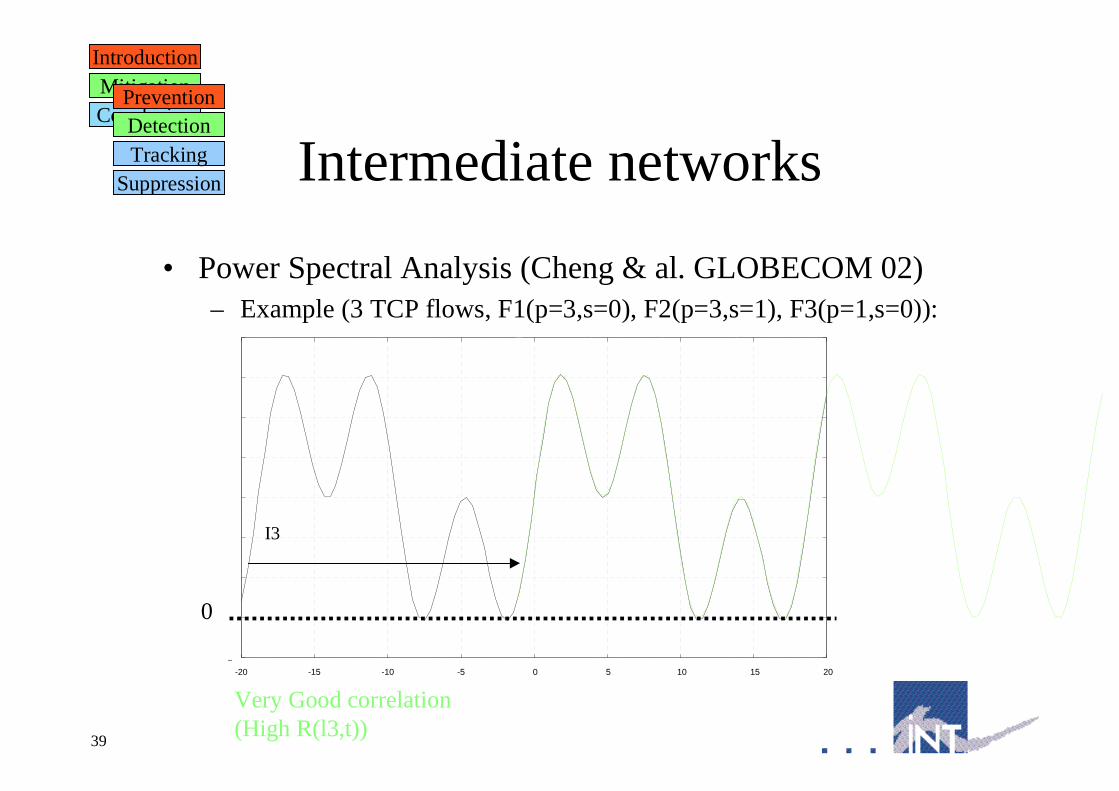
Intermediate networks
• Power Spectral Analysis (Cheng & al. GLOBECOM 02)– Example (3 TCP flows, F1(p=3,s=0), F2(p=3,s=1), F3(p=1,s=0)):
IntroductionMitigationConclusion
PreventionDetectionTracking
Suppression
Very Good correlation(High R(l3,t))
I3
0

40
Intermediate networks
• Power Spectral Analysis (Cheng & al. GLOBECOM 02)– Represent “power” of various periods using periodogram.
IntroductionMitigationConclusion
PreventionDetectionTracking
Suppression
– Frequency representation should present “peaks” around 1/RTT values.
– Attacks flatten these peaks by distributing frequency power evenly.
xx x
xx
Degree of correlation (db)
Period (s)
xx
xx x x
0
Attack traffic
l1 l2
x
x
x x x
Degree of correlation (db)
Period (s)
xx
x
x
x
x x
0
TCP Traffic
xx
x x
xx
x
l3
F1+F2+F3
F3F3

41
Intermediate networks
• Power Spectral Analysis (Cheng & al. GLOBECOM 02)– Detection
• Selects an aggregate of flows from the same prefix.– Assumption 1: Flows from the same prefix have the similar RTT values.
– Assumption 2: Most flows are TCP.
– Assumption 3: Most packets are from long TCP flows.
• Use previously defined method to compute Power Spectral Density.
• Compare power of strongest frequency to power of other frequencies:– Small difference: Not TCP traffic.
– Large difference: TCP traffic.
IntroductionMitigationConclusion
PreventionDetectionTracking
Suppression
– Efficiency varies with TTL values/variations, degree of aggregation.
– Roughly 80% correct classification with real life normal traffic.
Detects Large Changes

42
Intermediate networks
• Wavelet based detection.– Representing time and frequencies power.
• Huang & al. (SIGCOMM 01).
• Barford & al. (IMW 02).
IntroductionMitigationConclusion
PreventionDetectionTracking
Suppression
43
Close to the attacker
• Challenges:– Instant variations sometimes do not provide enough information to
detect attacks.• Variations are small.
• Attack diluted over time.
• Statistical Process Control techniques– Developed to control quality of manufacturing processes.
• Well known techniques to detect small changes– Cumulative Sum (CuSum) Charts.
– Exponentially Weighted Moving Averages (EWMA) Charts.
IntroductionMitigationConclusion
PreventionDetectionTracking
Suppression

44
Close to the attacker
• Monitoring changes in the mean.• Change small compared to mean or variance values.
• Need to take deviation history into account.
• Use cumulative sum of deviations vs expected mean.
IntroductionMitigationConclusion
PreventionDetectionTracking
Suppression
0
0.2
0.4
0.6
0.8
1
1.2
1.4
1.6
0 2 4 6 8 10 12 14 16 18 20
Random(x)Expected mean: 0.5
Random(x)+0.1Expected mean: 0.5
-5
-4
-3
-2
-1
0
1
2
0 2 4 6 8 10 12 14 16 18 20

45
Close to the attacker
• Cumulative SUM techniques (Wang & al. INFOCOM 02).– Basic Idea:
• TCP connections:– Started with SYN packet
– Closed with FIN / RST packets.
• Ratio SYN/(FIN+RST) should be fixed.– Measure SYN at time t.
– Measure FIN+RST at time t+d where d is average duration of TCP flow.
– Assumption: traffic is symmetric.
• In the case of TCP SYN Flooding:– No answer when attack is successful.
– Ratio should increase.
• Use CUSUM to use scheme close to attacker.
IntroductionMitigationConclusion
PreventionDetectionTracking
Suppression
Uncorrelated Data
Detects small changes
Supports Aggregation
Univariate

46
Close to the attacker
• Cumulative SUM techniques (Wang & al. INFOCOM 02).– Processing:
• Xn normalised version of the measured value. # 0<=Xn<=1
• c=E(Xn) , a = max (c). # c is the mean for Xn
• X’n = Xn - a # X’ n < 0 when normal
• yn = (y n-1 + X'n)+ # yn > 0
– Detection:• Dn = 1 iff yn > T # T attack threshold
• Dn = 0 otherwise.
– Results:• Traffic: 1500-4000 SYN packets/s.
• Detects attacks as low as 35 SYN per second.
IntroductionMitigationConclusion
PreventionDetectionTracking
Suppression

47
Close to the attacker
• Cumulative SUM techniques.– Measurable parameters.
• Must exhibit some natural stability.– Ratio TCP SYN/FIN(RST) packets (Wang & al. INFOCOM 02).
– Number of source IP addresses in use in a specific network (Peng & al.GLOBECOM 03)
• Or transformed to exhibit some stability (Siris & al. TCP SYN,GLOBECOM 04)
• EWMA techniques– Measurable parameters.
• Bits/s. EWMA for autocorrelated data (Ye & al, IEEE Transactions onReliability 03)
• Bits/s. Holt-Winters Forecasting (Jake Brutlag, USENIX LISA 00).
IntroductionMitigationConclusion
PreventionDetectionTracking
Suppression

48
Multivariate approaches:
– Problem: curse of dimensionality.
– Start appearing:• 2 papers at SIGCOMM 05.
IntroductionMitigationConclusion
PreventionDetectionTracking
Suppression

49
Detection on theoperator side
• Conclusion– Some products now implement similar techniques.
– However:• Detection is today mostly performed on customer side.
• Or close to customer.
– Need to have a feedback to other mitigation phases.
IntroductionMitigationConclusion
PreventionDetectionTracking
Suppression

50
Link betweencustomer and operator
• Mostly phone oriented
IntroductionMitigationConclusion
PreventionDetectionTracking
Suppression
My web server is going down: Help !
Attack signature

51
Link betweencustomer and operator
• Remote TriggeredBlackhole Capability(Sprint, UUnet)– Triggers blackhole
creation inside ISPnetwork.
– By sending a newroute advertisementthrough BGP.
IntroductionMitigationConclusion
PreventionDetectionTracking
Suppression

52
Link betweencustomer and operator
• IETF ID Message Exchange working group IDMF
IntroductionMitigationConclusion
PreventionDetectionTracking
Suppression
<?xml version="1.0" encoding="UTF-8"?><idmef version="1.0" xmlns:idmef="http://iana.org/idmef"> <alert messageid="42760"> <analyzer analyzerid="HTTP Overload Module0.1"> <model> HTTP Overload Module </model> <version> 0.1 </version> </analyzer> <create_time ntpstamp="0"> <detect_time> 111755724 </detect_time> </create_time> <source spoofed="No"> <node> <address category="ipv4-addr"> <address>192.168.0.2</address> </address> </node>
<port> 1057 </port> </service> </source> <assessment> <impact> <severity> 1.096633 </severity> <completion> 1 </completion> <type> 1 </type> </impact> </assessment></idmef>
Attack signature

53
DoS mitigation techniques
• Usually divided in four phases:– Prevention
– Detection
– Tracking
– Suppression
– (Post Mortem)
IntroductionMitigationConclusion
DetectionPrevention SuppressionTracking
PreventionDetectionTracking
Suppression

54
Tracking
• Goals and problems in operator network– In theory: Find the source of packets matching a specific “pattern” .
• Find responsible to bring him in front of a court.
• Charge him for damages.
– In practice: Find the entry point of these packets in operatornetworks.
• Block packets as soon as possible to avoid useless traffic in operatornetwork.
– Why not use source address ?• Spoofed addresses.
• Asymmetric routes.
IntroductionMitigationConclusion
PreventionDetectionTracking
Suppression

55
Tracking
• Existing approaches– Extend flow information.
• On each network device, send some identifying information to thedestination along with the flow.
• Destination recovers identification information to guess the path topackets sources.
– Trace back flows.• From the destination, find sources among immediate neighbors.
• Ask neighbors to perform similar job.
IntroductionMitigationConclusion
PreventionDetectionTracking
Suppression

56
Extend flowinformation
• Two classes of approaches– Packet marking.
• Use specific packet selection strategy.
• Store identification information into IP packet.
• Storing space is limited.
– ICMP message.• Use common packet selection strategy.
• Build ICMP packet including captured packet and identificationinformation.
• Send both packets to the destination.
IntroductionMitigationConclusion
PreventionDetectionTracking
SuppressionExtend FlowTraceback

57
Packet Marking
• Packet Marking basics
Routeur 1
Routeur 0
Routeur 2
Routeur 3
Routeur 4
Attacker 1
Attacker 2
Victim
IntroductionMitigationConclusion
PreventionDetectionTracking
SuppressionExtend FlowTraceback
Packet 1
Packet 1
Packet 1
Packet 1
Packet 1Packet 1
Packet 2
Packet 2
Packet 2

58
• Packet Marking basics
Packet Marking
Routeur 1
Routeur 0
Routeur 2
Routeur 3
Routeur 4
Attacker 1
Attacker 2
Victim
= R3,R4
= R3,R1,R2,R0
IntroductionMitigationConclusion
PreventionDetectionTracking
SuppressionExtend FlowTraceback

59
Packet Marking
• Packet Marking basics:– Issue#0: Distance attenuation
Routeur 1
Routeur 0
Routeur 2
Routeur 3
Routeur 4
Attacker 1
Attacker 2
VictimPacket 1
Packet 1
Packet 1Packet 1
Packet 2
Packet 2
Only tags from R3!
IntroductionMitigationConclusion
PreventionDetectionTracking
SuppressionExtend FlowTraceback
Packet 1
Packet 2
Packet 2 Packet 1

60
Packet Marking
• Packet Marking basics:– Issue#1: Packet Overwrite
Routeur 1
Routeur 0
Routeur 2
Routeur 3
Routeur 4
Attacker 1
Attacker 2
VictimPacket 1
Packet 1
Packet 1
Packet 2
Packet 2
Packet 2
Packet 1
Packet 1
Packet 1
Packet 1
IntroductionMitigationConclusion
PreventionDetectionTracking
SuppressionExtend FlowTraceback

61
Packet Marking
• Packet Marking basics– Issue#2: Accidental collision
Routeur 1
Routeur 0
Routeur 2
Routeur 3
Routeur 4
Attacker 1
Attacker 2
VictimPacket 1
Packet 1
Packet 1
Packet 2
Packet 1
Packet 1
Packet 1
Packet 2
Packet 2
Packet 2
Packet 1
=
IntroductionMitigationConclusion
PreventionDetectionTracking
SuppressionExtend FlowTraceback

62
Packet Marking
• Packet Marking basics– Issue#3: Voluntary collision
Routeur 1
Routeur 0
Routeur 2
Routeur 3
Routeur 4
Attacker 1
Attacker 2
VictimPacket 1
Packet 1
Packet 1
Packet 1
Packet 1
Packet 1
Packet 2
Packet 2
Packet 1
Packet 2
=
IntroductionMitigationConclusion
PreventionDetectionTracking
SuppressionExtend FlowTraceback

63
Packet Marking
• Mathematical problems that play a role in packet marking:– Birthday paradox:
• Take n elements x1…xn from a set made of N with a probability p = 1/N.
• the probability that ∃ j,k such that xj = xk is
Pcollision(n,N) = 1 - (1 - 1/N) (n . (n-1))/2
IntroductionMitigationConclusion
PreventionDetectionTracking
SuppressionExtend FlowTraceback
– Coupon collector problem:• Let’s consider a set of n stamps.
– We have to collect n stamps s1…sn to win.
– The probability to get stamp si on a box is 1/n
• The number of boxes you have to buy to get n coupons is :
E(b) = n . (log(n)+1)

64
Packet Marking
• Mathematical problems that play a role in packet marking:– Packet marking probabilities
• Let’s consider packets with a single stamp.
• Marking probability by each router is p.
• Marking probability by router Rd at d hops from receiver is:
PRd = p . (1 - p)d-1
• Probability that marking by routers R’d at more d hops from receiver is notoverwritten is :
PR’d = (1 - p)d
(Note: p>1/2 �
PRd < PR’d , p<1/2
�
PR’d > PRd)
IntroductionMitigationConclusion
PreventionDetectionTracking
SuppressionExtend FlowTraceback

65
Packet Marking
• Probabilistic packet marking (Savage & al. SIGCOMM 00)– Only use 1 field and store field in IP header ID field.
• May be treated by ASICS: prevent packet punting to GP processor.
• Packet marking is still probabilistic (P = 1/r).– Performance issues.
– Limit impact on fragmentation (ID field modification generates packet rejection).
• Why ?:– Fragmented traffic constitutes a small part of overall traffic (~0.45% Shannon &
al. ACM TON 2002)
– Marking is probabilistic (not every packet is marked).
– Recall Pnotmarked = (1-1/r)r ,r=30 � Pnotmarked = 0.37
– Ploss = Pmarked . Pfrag = (1 - 0.37) . 0.0045 = 0.0028 (0.28%)
– Average packet loss on the internet : 0.011 (1.1%).
– How can you store addresses in a 16bits field ?
IntroductionMitigationConclusion
PreventionDetectionTracking
SuppressionExtend FlowTraceback

66
Packet Marking
• Probabilistic packet marking (Savage & al. SIGCOMM 00)– How do you store addresses in a 16bits field ?
• Store edges (couple of adresses) instead of addresses.
• Need to capture packets that were captured by previous router.
– Divide space requirements by 2 using xor property:• A ⊕ B ⊕ A = B, B ⊕ A ⊕ B = A.
A B C D VA + BB + CC + D
B + CC + D
DC
BA + B
A
IntroductionMitigationConclusion
PreventionDetectionTracking
SuppressionExtend FlowTraceback

67
Packet Marking
• Probabilistic packet marking (Savage & al. SIGCOMM 00)– How do you know B is between A and C ?
• Include distance field to indicate distance between B and V.
• Distance initialized to 0 by edge router
• Incremented by each marking router.
– We still need a lot of bits !• Reduce space requirements by using n address slices
• Space requirement divided by n but packets# required multiplied by n
• Use log n to indicate slice id.– 16-log n bits for address slice.
– log n bits for slice id.
Address slice8
Slide id3
Distance5
ID Field
IntroductionMitigationConclusion
PreventionDetectionTracking
SuppressionExtend FlowTraceback

68
Packet Marking
• Probabilistic packet marking (Savage & al. SIGCOMM 00)– However IP address chunks are not necessarily unique:
192.200.128.12
192.133.128.12
3 identical chunks
– XOR of IP address chunks bears the same problem.
– You need to break IP addresses structure in the chunk.• Idea: “mix” another values with bit interleaving to break the structure.
• You cannot choose a random number (no way to find back the address).
• Idea: Use hash function (pseudo random).
Mainly due to addressing method in the Internet
IntroductionMitigationConclusion
PreventionDetectionTracking
SuppressionExtend FlowTraceback

69
Packet Marking
• Probabilistic packet marking (Savage & al. SIGCOMM 00)– How do you perform reconstruction ?
• Store n stamps.
• Order stamps according to distance into d bins.
1 2 3 d...
• Order stamps according to chunk id i.• You need d bins (Vertical coupon collector problem)• With k chunks (Horizontal coupon collector problem)
IntroductionMitigationConclusion
PreventionDetectionTracking
SuppressionExtend FlowTraceback

70
Packet Marking
• Probabilistic packet marking (Savage & al. SIGCOMM 00)– How do you perform reconstruction ?
• For stamps S in bin 1 (Stamps only include last node before victim)
IntroductionMitigationConclusion
PreventionDetectionTracking
Suppression
V 1 21 2
2 chunks
Chunks received
O2
E2
address
De-interleaving
hash
O1
O2
O1
O2
H( ) = E2
E1
2H( ) = E2
E1
O1
H( ) = E2
E1
O2
O1
H( ) = E2
E1
O2
...(m[1]k)2 combinations
with distance=1
Extend FlowTraceback

71
Packet Marking
• Probabilistic packet marking (Savage & al. SIGCOMM 00)– How do you perform reconstruction ?
• For stamps S in bin n
IntroductionMitigationConclusion
PreventionDetectionTracking
Suppression
V 1 21 2
2 chunks
Chunks received
O2
E2
address
De-interleaving
hash
O1
O2
O1
O2
H( ) = E2
E1
2H( ) = E
2E1
...m[n-1].(m[n]k)2 combinations
with distance=n
1 2
1 2Set of valid addresses for n-1:
1 2⊕⊕⊕⊕
⊕⊕⊕⊕ 1 2O2
O1H( ) = E
2E1
1 2⊕⊕⊕⊕
O1
O2
H( ) = E2
E1
1 2⊕⊕⊕⊕
Extend FlowTraceback

72
Improvements
• Make more space– No addresses, use hash values and network map (Song & al. INFOCOM 01).
– Use short space for address and larger space for checksum (Goodrich CCS 02).
• Use other coding techniques– Algebraic polynomial coding (Dean & al INFOCOM 01).
– Probabilistic coding (Adler STOC 03).
• Change probabilistic selection– Adjusted probabilistic selection (Peng & al. Networking 02)
IntroductionMitigationConclusion
PreventionDetectionTracking
SuppressionExtend FlowTraceback

73
ICMP Message
• ICMP message basics
Routeur 1
Routeur 0
Routeur 2
Routeur 3
Routeur 4
Attacker 1
Attacker 2
VictimPacket 1
Packet 1
Packet 1
Packet 2
Packet 2
Packet 2
Packet 1
Packet 1
Packet R1
Packet R1
Packet 1Packet R1
IntroductionMitigationConclusion
PreventionDetectionTracking
SuppressionExtend FlowTraceback

74
• ICMP message basics– Packet collision issues similar to marking issues
• Packet attenuation:– Far worse than packet marking (probability to generate packet is much
lower).
• Packet overwrite:– Does not apply.
• Accidental Collisions: Two routers generate the same packet.– Very unlikely. Code size is much bigger.
• Voluntary collisions: Attacker generates false ICMP packets.– Much easier than with packet marking.
ICMP Message
IntroductionMitigationConclusion
PreventionDetectionTracking
SuppressionExtend FlowTraceback

75
ICMP Message
• Original ICMP traceback (Bellovin & al. 2000-2003)– Basic idea:
• Capture packets with very low probability (1/20000).
• Send ICMP message including captured packet to the destination.– Source of packet is capturing router.
– Packet format (based on version 3 of the draft):0 1 2 3
0 1 2 3 4 5 6 7 8 9 0 1 2 3 4 5 6 7 8 9 0 1 2 3 4 5 6 7 8 9 0 1
+-+-+-+-+-+-+-+-+-+-+-+-+-+-+-+-+-+-+-+-+-+-+-+-+-+-+-+-+-+-+-+-+
| Type | Code=0 | Checksum |
+-+-+-+-+-+-+-+-+-+-+-+-+-+-+-+-+-+-+-+-+-+-+-+-+-+-+-+-+-+-+-+-+
| Message body |
+-+-+-+-+-+-+-+-+-+-+-+-+-+-+ .....-+-+-+-+-+-+-+-+-+-+-+-+-+-+-+
IntroductionMitigationConclusion
PreventionDetectionTracking
SuppressionExtend FlowTraceback

76
ICMP Message
• Original ICMP traceback (Bellovin & al. 2000-2003)– Tag values:
0x01 Back Link
0x02 Forward Link
0x03 Interface Name
0x04 IPv4 Address Pair
0x05 IPv6 Address Pair
0x06 MAC Address Pair
0x07 Operator-Defined Link Identifier
0x08 Timestamp
0x09 Traced Packet Contents
0x0A Probability
0x0B RouterId
0x0C HMAC Authentication Data
0x0D Key Disclosure List
0x0E Key Disclosure
0x0F Public-Key Information
MarkingRouter
packet packet
IntroductionMitigationConclusion
PreventionDetectionTracking
SuppressionExtend FlowTraceback

77
ICMP Message
• Original ICMP traceback (Bellovin & al. 2000-2003)– Authentication scheme
Key1 lifetime Key2 lifetime Key3 lifetime
Time
Router
Victim Key1 lifetime
Key2 lifetime
Key3 lifetime
NetworkTraversal
Key1 divulgation Key2 divulgation
Victim can authenticatepackets received during key1lifetime
Victim can authenticatepackets received during key2lifetime
– Key n is authenticated using public key infrastructure.
IntroductionMitigationConclusion
PreventionDetectionTracking
SuppressionExtend FlowTraceback

78
ICMP Message
• Existing ICMP message approaches:– ICMP traceback (itrace, Bellovin 2000-2003)
• Itrace IETF wg (2000)
• Intention based traceback (Mankin & al. 2001)
• Reverse traceback (Barros 2000)
• Active traceback (Yamada 2002)
– Mostly dead since mid-2002.
– Regain activity since beginning 2003.• Version 3 of original draft.
– Closed beginning 2004.
– Still people are working on improving ICMP traceback• Cumulative traceback (Thing & al. IEEE VTC 2005).
IntroductionMitigationConclusion
PreventionDetectionTracking
SuppressionExtend FlowTraceback

79
Trace backflows
• Basics
Routeur 1
Routeur 0
Routeur 2
Routeur 3
Routeur 4
Attacker 1
Attacker 2
VictimPacket 1
Packet 1
Packet 1
Packet 2
Packet 2
Packet 2
Packet 1Packet 1
IntroductionMitigationConclusion
PreventionDetectionTracking
Suppression
Where is Packet R1 coming from ?
Where is Packet R1 coming from ?
Where is Packet R1 coming from ?
Where is Packet R1 coming from ?
Extend FlowTraceback

80
Trace backflows
• Existing traceback approaches– Reactive
• Manual– Input debugging (Widely used in operators networks).
» Netflow, sflow, cflow, ...
» Various improvements in ACLs.
» IP packet tracer (Cisco).
• Automated– Without pattern re-evaluation:
» Dostrack, (MCI 1997).
» Centertrack (UUnet 1999).
» ICMP backscatter (UUnet, 2002).
» Backhacking (Burch & al. 1999).
– With pattern re-evaluation (Pushback, Floyd & al. 2001).
IntroductionMitigationConclusion
PreventionDetectionTracking
Suppression
Widely usedin practice
Extend FlowTraceback

81
Trace backflows
• Existing traceback approaches– Reactive
• Hop by hop.
• Edge tracking.– Mainly extensions of hop by hop techniques.
– Preventive• Sample packet capture
– Trajectory sampling (Duffield & al. 2001)
• General packet capture– Hash based IP traceback (Snoeren & al. 2002)
IntroductionMitigationConclusion
PreventionDetectionTracking
SuppressionExtend FlowTraceback

82
Reactive approaches
• Manual flow tracking– Basic idea:
• From a description of the traffic generating the attack– Destination, specific transport protocol, specific packet headers.
• Find the neighbours from which most of the traffic is coming.– Most of: Parameter to be determined on a case by case basis.
– Find the neighbours:• Most links in operator networks are point to point.
• Find incoming interface ⇔ find the neighbours.
IntroductionMitigationConclusion
PreventionDetectionTracking
Suppression
Router
Extend FlowTraceback

83
Reactive approaches
• Manual flow tracking– Find incoming interfaces.
• Flow capture functionality– Several flavours:
» Juniper: cflowd.
» Foundry networks: Sflow.
» Cisco: Netflow.
» Howto: Activate netflow on a specific interface.
Retrieve incoming interface for flows matching pattern.
IntroductionMitigationConclusion
PreventionDetectionTracking
Suppression
src_ip dst_ip in_if out_if s_port d_port pkts bytes prot src_as dst_as192.xx.xxx.69 194.yyy.yyy.2 29 49 1308 77 1 40 6 xxx ddd192.xx.xxx.222 194.yyy.yyy.2 29 49 1774 1243 1 40 6 xxx ddd192.xx.xxx.108 194.yyy.yyy.2 29 49 1869 1076 1 40 6 xxx ddd192.xx.xxx.159 194.yyy.yyy.2 29 49 1050 903 1 40 6 xxx ddd192.xx.xxx.54 194.yyy.yyy.2 29 49 2018 730 1 40 6 xxx ddd
Extend FlowTraceback

84
Reactive approaches
• Automated flow tracking.– Pushback (Floyd & al. 2001)
• Implemented in routers. (no remote configuration)
• Combines 3 phases:– (Detection, pattern elaboration), Tracking, Suppression.
• Detection.– Monitors line-card output queues (output queues recover traffics from several
incoming line-cards).
– When packet loss bypass a given level, we recover rejected packets.
» Rejected packets are the cause of the problem (independently from numberof packets).
Small flows may cause high rejection rate.
» Packets recovered constitute a fair representation of rejected packets.
– From recovered packets we can generate patterns describing aggregates.
» Select the aggregate generating most of the packet loss.
IntroductionMitigationConclusion
PreventionDetectionTracking
SuppressionExtend FlowTraceback

85
Reactive approaches
• Automated flow tracking.– Pushback (Floyd & al. 2001)
• Tracking (local):– From the general packet loss rate r and number of packets recovered we can
estimate the packet rate matching the pattern (p).
– Compute reasonable rate limit of the aggregate : p’ = p - p . r.
– Compute the share of each incoming interface (p’ 1…p’ n).
• Suppression:– Select interface with the largest contribution I1…Ik.
– Rate limit the aggregate matching the pattern on each contributing interfaceIj to p’ i.
– Note that the rate limit does not alter conditions for sender/receiver !
IntroductionMitigationConclusion
PreventionDetectionTracking
SuppressionExtend FlowTraceback

86
Reactive approaches
• Automated flow tracking.– Pushback (Floyd & al. 2001)
• Tracking (remote):– For each interface I1…Ik determine adjacent router
R1…Rk
– Send aggregate description (pattern) and rate limit torouters R1…Rk.
– Ri has to re-evaluate aggregate pattern.
» Sharpen destination address definition to onlyinclude traffic headed to the outbound router:
195.269/16 -> 195.269.153/26
– Ri performs local tracking, suppression and remotetracking operations.
IntroductionMitigationConclusion
PreventionDetectionTracking
Suppression
A1 A2 A3
R1 R2
R3 R4 R5
R6
V1
Extend FlowTraceback

87
Reactive approaches
• Automated flow tracking.– Pushback (Floyd & al. 2001)
• Problems:– When do you stop tracking?
» No more router to call.
» Depth specified in tracking request.
– When do you stop rate limiting?
» Expiration time specified in tracking request.
– How do you know the attack has not stopped ?
» R must re-evaluate rate-limit based on:
*Local packet rejection rate on incoming rate limited interfaces.
*Remote packet rejection rate on remote incoming rate limited interfaces.
*Packet loss rate on outgoing interface.
IntroductionMitigationConclusion
PreventionDetectionTracking
Suppression
A1 A2 A3
R1 R2
R3 R4 R5
R6
V1
Extend FlowTraceback

88
Preventive Approaches
• General packet capture (Snoeren & al. SIGCOMM 01)– Outcome:
• IP packet Traceback (IPPT, partridge, 2002)
• Plan to form IETF wg (beginning 2002).
• An Architecture for IP Packet Tracing (draft, Keeny, 2002).
• However change of chair in itrace end 2002 seemed to have soften thewill to create a new wg on the same topic.
– Basic ideas:• Keep all packets. Don’ t sample traffic.
• Don’ t send packets to collector. Keep packets on routers.
• Problems:– 10 line cards routers x 100Mpkts/s = 1Gpkts/s.
– Average: 300 bytes/pkt = 300G bytes/s to store !
– Keep data 60 s � 1.8Tbytes to store.
IntroductionMitigationConclusion
PreventionDetectionTracking
SuppressionExtend FlowTraceback

89
Preventive Approaches
• General packet capture (Snoeren & al. SIGCOMM 01)– Reducing data size.
• Keep only invariant part of the packet (I).
• Idea: Use a bloom filter.
IntroductionMitigationConclusion
PreventionDetectionTracking
Suppression
2m cellsof 1 bit
I
m bits
H1(I) = 1000110001…1
Hi(I) = 0100010001…0
Hk(I) = 1100010101…1
1
1
1
Extend FlowTraceback

90
Preventive Approaches
• General packet capture (Snoeren & al. SIGCOMM 01)– Reducing data size.
• Keep only invariant part of the packet (I).
• Idea: Use a bloom filter.
IntroductionMitigationConclusion
PreventionDetectionTracking
Suppression
2m cellsof 1 bit
Ij
H1(Ij) = 0010110001…1
Hi(Ij) = 1110010001…0
Hk(Ij) = 0000010101…1
1
11
1
1
1
Extend FlowTraceback

91
Preventive Approaches
• General packet capture– Reducing data size.
• After n packets theprobability to have acollision is:
P = (1 - (1 - 1/2m) k . n ) k
• k = 3, m = 4, n = 3
P = 8.5%.
• Average data reductionratio:
N = 300*8*3/24 = 450 !
IntroductionMitigationConclusion
PreventionDetectionTracking
SuppressionExtend FlowTraceback

92
• General packet capture (Snoeren & al. SIGCOMM 01)– Tracking architecture.
• 3 levels– Area Managers: STM (SPIE Traceback Manager).
– Collectors: SCAR (SPIE Collection and Reduction Agents)
– Routers: DGA (Data Generation Agents)
Preventive Approaches
IntroductionMitigationConclusion
PreventionDetectionTracking
Suppression
AreaManager
AreaManager
Router
Router
Router
Router
Router
Router
Router
Router
Router
Router
Collector CollectorCollector
Collector
Customer
Extend FlowTraceback

93
DoS mitigation techniques
• Usually divided in four phases:– Prevention
– Detection
– Tracking
– Suppression
– (Post Mortem)
IntroductionMitigationConclusion
DetectionPrevention SuppressionTracking
PreventionDetectionTracking
Suppression

94
Suppressingattacks
• At Victim premises– Filtering routers.
• TCP_Intercept (Cisco)
• Firewalls filtering well known DoS attack signatures.
• On operator network– Redirection.
– Ingress filtering/rate limiting.• ACLs, CAR.
IntroductionMitigationConclusion
PreventionDetectionTracking
Suppression

95
TCP Intercept
• Basic idea:• Limit the number of TCP SYN requests directed to a host.
• Queue TCP SYN request
IntroductionMitigationConclusion
PreventionDetectionTracking
SuppressionAt victimOperator
SpecificDestination
TCP SYN
TCP SYN ACK
Initial window
– Problems in the core/edge:• Are you sure you are receiving ACKs from the destination ?
• Delay. Much higher than in a LAN.– Queue size has to be much larger.
– Synchronisation effect.

96
Redirection
• Steps– Choose a not so important
blackhole router.
– Modify address-namemapping on customer side.
• DNS update.
– Announce more specificroute to blackhole.
• Using BGP or IGP.
– Make sure route does notleak.
• Configure appropriateroute-maps on peeringpoints.
OperatorNetwork
Slave ASlave C
Slave D
Victim B
Blackhole
IntroductionMitigationConclusion
PreventionDetectionTracking
SuppressionAt victimOperator

97
Redirection
OperatorNetwork
Slave ASlave C
Slave D
Victim B
Blackhole
• Steps– Choose a not so important
blackhole router.
– Modify address-namemapping on customer side.
• DNS update.
– Announce more specificroute to blackhole.
• Using BGP or IGP.
– Make sure route does notleak.
• Configure appropriateroute-maps on peeringpoints.
IntroductionMitigationConclusion
PreventionDetectionTracking
SuppressionAt victimOperator

98
Dropping/Rate limiting
• Access Control lists– Set of conditions carrying on packet headers values.
– Action (permit/drop).
• Rate limiting– Use ACL to specify traffic. Actions more elaborate (drop, mark, permit).
– Token Bucket (Burst Size, Mean Rate) to decide if flow is too aggressive.
– No buffers involved.
– Can be distributed using BGP.
IntroductionMitigationConclusion
PreventionDetectionTracking
SuppressionAt victimOperator

99
Existing products
• Usually combine several mitigation phases.• Distributed in nature.• Some are used by network operators
– Eg: AT&T (Riverhead), Qwest (Arbor), TELUS (Arbor).
– Some operators develop in house products (eg: Sprint, France Telecom).
• Main companies:– Riverhead networks (now bought by Cisco system).
– Arbor networks.
– Mazu networks.
– Many others.
• Often funded/spin offs of big router companies (Cisco/Juniper).
IntroductionMitigationConclusion

100
Existing products
• Riverhead networks.– Used by AT&T.
IntroductionMitigation
Monitors copy of trafficBuilds traffic ProfilesDetects changes in traffic profileAlerts RG when attack is detected
Monitors traffic (BGP)In line
• anti-spoofing, • anomaly recognition, • protocol analysis, • rate limiting
Conclusion

101
Existing products
• Sprint cleaning center (Agarwal &al., Sprint lab TR, 2004)
IntroductionMitigationConclusion

102
Final words
• Will we see DoS mitigation measures implemented in routers?– Technical perspective:
• A lot of tools are already there.– ACLs, Netflow, NBar, QoS services, uRPF ...
• Most mitigation schemes make use of them.
• But mitigators also use some more complex tools:– Pattern matching, stateful filtering, protocol parsing, normalisation, packet
marking …
IntroductionMitigationConclusion

103
Final words
• Will we see DoS mitigation measures implemented in routers?– Technical perspective:
IntroductionMitigationConclusion
�� � �
� � �� � �
� � �
� � � �
� � � �� � � � � � � � � � � � � � � � � � � � � � � �
�� � � �� � � � � � � ��
��� ��� �� �� � � ��
� �! �"# $ % � & �' (
)*
Source: Mckeown, HPSR 2002

104
Final words
• Will we see DoS mitigation measures implemented in routers?– Economical perspective:
• Carriers point of view.– DoS benefit network operators ...
» Customer pay for traffic received.
» Customer pay to stop attacks.
» Operator pays for outbound-inbound ratio.
IntroductionMitigationConclusion
– … that are able to stop at the edges ...
» Traffic uses unnecessary resources.
– … BIG attacks.
» BIG attacks target mostly BIG customers.
» BIG attacks are easier to stop and do not occur so often.
– However !
» DoS often associated with poor QoS by smaller customers.
» no DoS mitigation scheme by operator pushes customer to competitors.

105
Final words
Cleverness has never been seen associated with long delays.
Sun Tzu, The Art of War.
IntroductionMitigationConclusion