an overview of the conceptual design studies of hybrid
TRANSCRIPT
NLR – Royal Netherlands Aerospace Centre
CUSTOMER: European Commission
An Overview of the Conceptual Design Studies of Hybrid Electric Propulsion Air Vehicles in the Frame of Clean Sky2 Large Passenger Aircraft
NLR-TP-2020-118 | May 2020

UNCLASSIFIED
EXECUTIVE SUMMARY
Problem area
Air travel has increased considerably over the past decades and it is expected to double in the next two decades. The combination of the rising demand for air transport and the need to decrease environmental impact of aircraft (exploitation of non-renewable fossil fuels, emission of greenhouse gasses and particles, and noise) put a strong challenge on the aircraft industry to come up with innovative technologies. In the automotive industry hybrid and fully electric cars have been developed in order to reduce environmental impact. In the aircraft industry, fully electric propulsion has been introduced for light aircraft so far. The low power-to-weight and energy-to-weight ratios of present state-of-the-art electric components, in particular of batteries, hold back the development of fully electric commercial passenger aircraft in the short term. Nevertheless, Hybrid Electric Propulsion (HEP) systems may bring solutions sooner by combining state of the art turbofan engines with innovative electric systems. There is a strong interest to analyze and optimize the potential fuel, energy and emission reductions of HEP for single aisle passenger aircraft.
An Overview of the Conceptual Design Studies of Hybrid Electric Propulsion Air Vehicles in the Frame of Clean Sky2 Large Passenger Aircraft
REPORT NUMBER NLR-TP-2020-118 AUTHOR(S) T. Zill M. Iwanizki P. Schmollgruber S. Defoort C. Döll M. Hoogreef R. de Vries W.J. Vankan W.F. Lammen REPORT CLASSIFICATION UNCLASSIFIED DATE May 2020 KNOWLEDGE AREA(S) Computational Mechanics and Simulation Technology Aerospace Collaborative Engineering and Design DESCRIPTOR(S) Hybrid Electric Propulsion MASS single aisle aircraft Clean Sky2 Large Passenger Aircraft

UNCLASSIFIED
EXECUTIVE SUMMARY
GENERAL NOTE This report is based on a presentation held at the Aerospace Europe Conference (AEC) 2020, Bordeaux, 25/02/2020.
NLR
Anthony Fokkerweg 2
1059 CM Amsterdam, The Netherlands
p ) +31 88 511 3113
e ) [email protected] i ) www.nlr.nl
Description of work
In the Clean Sky 2 Large Passenger Aircraft (LPA) program the potential of innovative HEP air vehicle concepts has been investigated by the projects ADEC (Advanced Engine and Aircraft Configuration) and NOVAIR (Novel Aircraft Configurations and Scaled Flight Testing Instrumentation). In a combined effort the members of the two projects worked closely together to identify promising technologies for air vehicle concepts that utilize hybrid electric powertrains (taking into account the estimated technology level of 2035). The vehicle design studies were divided onto the three distinct teams of DLR, TU Delft/NLR (NOVAIR), and ONERA. NLR specifically focused on a parallel HEP architecture ‘retrofitted’ to an Airbus A320neo reference aircraft. To support the study a parametric system model and tool chain was developed, called MASS: Mission, Aircraft and Systems Simulation for HEP performance analysis and system optimization.
Results and conclusions
The results of the studies indicate that HEP concepts offer a potential for block fuel reduction up to about 10% for aircraft with entry into service (EIS) in 2035. But this potential depends on many aspects like assumed specific power and energy values for electric components, the type of HEP architecture and aircraft configuration considered, and operational limitations and mission targets taken into account.
Applicability
The results of the studies can be used for further detailed research of HEP technology and may support analysis of future scenarios with respect to sustainable aviation in general. The NLR tool MASS can be used for performance analysis of an arbitrary aircraft mission combination with HEP. The efficient simulation models can be used for sensitivity analysis and optimization studies supporting the conceptual and multidisciplinary design of aircraft with HEP, or for retrofit studies.

NLR – Royal Netherlands Aerospace Centre
AUTHOR(S):
T. Zill DLR M. Iwanizki DLR P. Schmollgruber ONERA S. Defoort ONERA C. Döll ONERA M. Hoogreef TU Delft R. de Vries TU Delft W.J. Vankan NLR W.F. Lammen NLR
NLR-TP-2020-118 | May 2020
CUSTOMER: European Commission
An Overview of the Conceptual Design
Studies of Hybrid Electric Propulsion Air
Vehicles in the Frame of Clean Sky2 Large
Passenger Aircraft
2
NLR-TP-2020-118 | May 2020
APPROVED BY: Date
AUTHOR W. Lammen 31-03-2020
REVIEWER H. Jentink 31-03-2020
MANAGING DEPARTMENT A.A. ten Dam 13-05-2020
CUSTOMER European Commission
CONTRACT NUMBER CS2-LPA-GAM-2018/2019-01
OWNER NLR + partner(s)
DIVISION NLR Aerospace Vehicles
DISTRIBUTION Unlimited
CLASSIFICATION OF TITLE UNCLASSIFIED
This report is based on a presentation held at the Aerospace Europe Conference (AEC) 2020, Bordeaux, 25/02/2020. The contents of this report may be cited on condition that full credit is given to NLR and the authors. This publication has been refereed by the Advisory Committee AEROSPACE VEHICLES (AV).

3
NLR-TP-2020-118 | May 2020
Contents
Abstract 4
1 Introduction 4
2 HEP aircraft design studies by DLR 4 2.1 Description of evaluation phases 5 2.2 Conclusion 6
3 HEP aircraft design studies TU Delft 6 3.1 Design approach 7 3.2 Aero-Propulsive Efficiency Requirements 7 3.3 Synthesis of design studies 7
4 Boosted turbofan parallel HEP investigations by NLR 9 4.1 Design approach 9 4.2 Conclusion 10
5 HEP aircraft design studies by ONERA 11
6 Conclusion 13
7 Acknowledgement 14
8 Abbreviations and acronyms 14
9 References 14

4
NLR-TP-2020-118 | May 2020
Abstract
1 Introduction
2 HEP aircraft design studies by DLR
1
AN OVERVIEW OF THE CONCEPTUAL DESIGN STUDIES OF HYBRID ELECTRIC
PROPULSION AIR VEHICLES IN THE FRAME OF CLEAN SKY 2 LARGE PASSENGER AIRCRAFT
Thomas Zill(1)
, Michael Iwanizki (2)
, Peter Schmollgruber (3)
, Sebastien Defoort(4)
, Carsten Döll(5)
, Maurice Hoogreef
(6), Reynard de Vries
(7), Jos Vankan
(8), Wim Lammen
(9)
(1)German Aerospace Center (DLR), Institute of System Architectures in Aeronautics,
Hein-Saß-Weg 22, 21129 Hamburg, Germany, Email: [email protected] (2)
German Aerospace Center (DLR), Institute of Aerodynamics and Flow Technology, Lilienthalplatz 7, 38108 Braunschweig, Germany Email: [email protected]
(3) The French Aerospace Lab (ONERA), 2 Avenue Edouard Belin, 31000 Toulouse, France,
Email: [email protected] (4)
The French Aerospace Lab (ONERA), 2 Avenue Edouard Belin, 31000 Toulouse, France Email: [email protected]
(5) The French Aerospace Lab (ONERA), 2 Avenue Edouard Belin, 31000 Toulouse, France
Email: [email protected] (6)
Delft University of Technology (TU Delft), Faculty of Aerospace Engineering, Kluyverweg 1, 2629HS Delft, The Netherlands, Email: [email protected]
(7) Delft University of Technology (TU Delft), Faculty of Aerospace Engineering, Kluyverweg 1, 2629HS Delft,
The Netherlands, Email: [email protected] (8)
Royal Netherlands Aerospace Center (NLR), Aerospace Vehicles Division, Anthony Fokkerweg 2, 1059 CM Amsterdam, Email: [email protected]
(9) Royal Netherlands Aerospace Center (NLR), Aerospace Vehicles Division, Anthony Fokkerweg 2, 1059
CM Amsterdam, Email: [email protected]
KEYWORDS: hybrid electric propulsion, conceptual aircraft design, novel aircraft concepts, Clean Sky 2 ABSTRACT:
In the Clean Sky 2 Large Passenger Aircraft (LPA) program the potential of innovative hybrid electric propulsion (HEP) air vehicle concepts has been investigated by the projects ADEC (Advanced Engine and Aircraft Configuration) and NOVAIR (Novel Aircraft Configurations and Scaled Flight Testing Instrumentation). In a combined effort the members of the two projects worked closely together to identify promising technologies for air vehicle concepts that utilize hybrid electric powertrains. The vehicle design studies were divided onto the three distinct teams of DLR, TU Delft/NLR (NOVAIR), and ONERA. This paper will summarize the design efforts and the results obtained from the HEP design space exploration. 1. INTRODUCTION
In this study the HEP design investigations were driven by the potential advent of technology bricks that could enable hybrid electric flight for air vehicles beyond the size restrictions of CS-23. Each team was tasked with covering different aspects of the vast design space to provide a thorough assessment of the HEP technology potential for commercial airliners. To streamline the design activities and to provide for a proper basis for comparison, the teams established common research baseline aircraft. On this groundwork the
HEP studies have been conducted at the conceptual aircraft design level primarily for AIRBUS A320-sized vehicles with reduced mission range and the possibility to operate at lower cruise Mach numbers, to account for the still limited prospected power densities of batteries in the future. In the following sections, an overview of the activities and results of each team is given. 2. HEP AIRCRAFT DESIGN STUDIES BY DLR
The design and evaluation process of HEP aircraft at DLR comprises several phases. This allows for covering a wide portion of the design space, to identify most promising aircraft concepts, and to look at them in detail. In the first step, more than thirty aircraft configurations were in scope of the HEP studies. In each phase, an analysis of configurations was performed and these concepts were ranked. The most promising configurations were transferred into the next phase. Hence, the number of configurations was reduced in each of the steps. In each subsequent phase, the level of fidelity of tools and methods was increased. In Fig. 1 the general overview of this process is shown.
Figure 1. Overview of DLR evaluation process
5
NLR-TP-2020-118 | May 2020
2.1 Description of evaluation phases
2
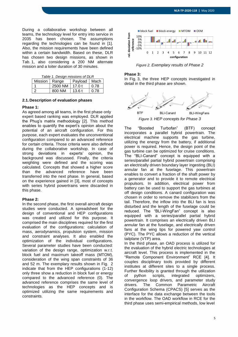
During a collaborative workshop between all teams, the technology level for entry into service in 2035 has been chosen. The assumptions regarding the technologies can be found in [1]. Also, the mission requirements have been defined within a certain bandwidth. Based on these, DLR has chosen two design missions, as shown in Tab. 1, also considering a 200 NM alternate mission and a loiter duration of 30 minutes.
Table 1. Design missions of DLR
Mission Range Payload Mach
1 2500 NM 17.0 t 0.78
2 800 NM 13.6 t 0.78
2.1. Description of evaluation phases
Phase 1: As agreed among all teams, in the first phase only expert based ranking was employed. DLR applied the Phug’s matrix methodology [2]. This method enables to quantify the expert’s opinion about the potential of an aircraft configuration. For this purpose, each expert evaluates the unconventional configuration compared to an advanced reference for certain criteria. Those criteria were also defined during the collaborative workshop. In case of strong deviations in experts’ opinion, the background was discussed. Finally, the criteria weighting were defined and the scoring was calculated. Concepts that showed a higher score than the advanced reference have been transferred into the next phase. In general, based on the experience gained in [3], most of concepts with series hybrid powertrains were discarded in this phase. Phase 2: In the second phase, the first overall aircraft design studies were conducted. A spreadsheet for the design of conventional and HEP configurations was created and utilized for this purpose. It comprised the main disciplines required for the first evaluation of the configurations: calculation of mass, aerodynamics, propulsion system, mission and constraint analyses. It also enabled the optimization of the individual configurations. Several parameter studies have been conducted: variation of the design range, optimization w.r.t. block fuel and maximum takeoff mass (MTOM), consideration of the wing span constraints of 36 and 52 m. The exemplary results shown in Fig. 2 indicate that from the HEP configurations (1-12) only three show a reduction in block fuel or energy compared to the advanced reference (0). The advanced reference comprises the same level of technologies as the HEP concepts and is optimized utilizing the same requirements and constraints.
Figure 2. Exemplary results of Phase 2
Phase 3: In Fig. 3, the three HEP concepts investigated in detail in the third phase are shown.
Figure 3. HEP concepts for Phase 3
The “Boosted Turbofan” (BTF) concept incorporates a parallel hybrid powertrain. The electrical machine supports the gas turbine, utilizing the energy from the battery, if additional power is required. Hence, the design point of the gas turbine can be optimized for cruise conditions. The “BLI-Canard” concept is equipped with a series/parallel partial hybrid powertrain comprising an electrically driven boundary layer ingesting (BLI) annular fan at the fuselage. This powertrain enables to convert a fraction of the shaft power by a generator and to provide it to remote electrical propulsors. In addition, electrical power from battery can be used to support the gas turbines at off design conditions. A canard configuration was chosen in order to remove the stabilizers from the tail. Therefore, the inflow into the BLI fan is less disturbed and the length of the fuselage could be reduced. The “BLI-WingFan” concept is also equipped with a series/parallel partial hybrid powertrain. It comprises an electrically driven BLI annular fan at the fuselage, and electrically driven fans at the wing tips for powered yaw control (PYC). The PYC allows a reduction of the vertical tailplane (VTP) area. In the third phase, an OAD process is utilized for the evaluation of the hybrid electric technologies at aircraft level. This process is implemented in the “Remote Component Environment” RCE [4]. It couples disciplinary tools provided by different institutes at different sites to a single process. Further flexibility is granted through the utilization of python scripts, integrated optimizers, convergence loop drivers, and parameter study drivers. The Common Parametric Aircraft Configuration Schema (CPACS) [5] serves as the interface for the data exchange between the tools in the workflow. The OAD workflow in RCE for the third phase uses semi-empirical methods, low level

6
NLR-TP-2020-118 | May 2020
2.2 Conclusion
3 HEP aircraft design studies TU Delft
3
physics based tools, and surrogate models. A detailed description of the workflow and the so called HEP-module that has been developed in the scope of this work and calculates the hybrid electric related aspects is provided in [1]. For the validation of the OAD workflow the CERAS database [6] is used. For the evaluation of the potential of an unconventional configuration, an appropriate reference at the same technology level is mandatory. Therefore, for each mission a reference configuration is designed with the same workflow that is used for the calculation of the HEP configurations, under consideration of the same requirements and constraints, see Fig. 4.
Figure 4. Reference configurations For the design of the HEP configurations, parameter studies regarding the degree of hybridization (i.e. maximum power fraction provided by the battery), the wing aspect ratio, the length of the fuselage for the BLI-Canard, and the size of the tip fans respectively the area of the VTP for the BLI-WingFans. In Fig. 5, the most promising configurations designed by the OAD workflow are shown. The additional BLI-ETF configuration represents the BLI-WingFan concept with the size of the tip fans of zero.
Figure 5. Final HEP configurations In Fig. 6, the comparison of the novel configurations to the advanced reference is shown. These results represent the 800NM mission. The same trends and orders of magnitude are observed for the 2500NM mission.
Figure 6. Comparison of configurations for 800NM
mission 2.2. Conclusion
The final results indicate that all HEP concepts offer a reduction in block fuel and energy at aircraft level for the technology level assumed. The order of magnitude is about 1%-3%. Also, all HEP concepts are heavier (see MTOM and OEM) than the reference. Regarding the lift-to-drag (L/D) ratio, the BLI-Canard and the BLI-WingFan show minor benefits. Further studies have been conducted in order to evaluate the impact of the individual technologies considered for the chosen configurations. The most promising appears to be the boosting of the gas turbines. It reduces the block fuel consumption by 2% and is included in all configurations according to the chosen powertrain architectures. The BLI appears not beneficial, because of the inadequately prescribed power split based on the requirement to ingest the whole boundary layer of the fuselage. A carefully chosen size of the BLI propulsor could improve the performance as shown in [6]. The powered yaw control does not show any benefits because the reduced size of the VTP does not compensate for the mass penalty of the distributed propulsors. The reduced length of the fuselage on the BLI-Canard configuration is the main driver for the advantage of this concept. Further investigations in Phase 4 are dedicated to the BTF configuration. A detailed description of the workflow update that has been performed in the scope of this project is provided in [7]. 3. HEP AIRCRAFT DESIGN STUDIES TU
DELFT
Earlier studies performed at TU Delft indicated that the initial combination of mission requirements and aircraft configurations did not lead to any benefits at aircraft level [9]. Nevertheless, these studies concluded that the parallel (“boosted”) turbofan and partial-turboelectric architecture were the most promising powertrain configurations [9,10]. Therefore, in this design iteration, a two-step approach was taken. First, the requirements were revisited, and a sensitivity study was performed to determine the aero-propulsive benefit required from the turboelectric aircraft configurations in order to provide a given energy reduction. This

7
NLR-TP-2020-118 | May 2020
3.1 Design approach
3.2 Aero-Propulsive Efficiency Requirements
3.3 Synthesis of design studies
4
process is described in Section 3.2. Subsequently, the lessons learned were applied in a synthesis study where different technologies offering synergistic aero-propulsive benefits were contrasted, as described in Section 3.3. 3.1. Design approach
The hybrid-electric design studies performed at TU Delft employ the Class-I sizing method described in [11], which has been validated in [12]. This sizing approach modifies the point-performance equation of the aircraft to account for aero-propulsive interaction effects between the propulsors and the airframe. This interaction is expressed as a change in lift Δ𝐶𝐿,, drag Δ𝐶𝐷, or
propulsive efficiency Δ𝜂p. These “delta” terms are
computed using simplified semi-empirical models for each type of distributed-propulsion system considered. The constraint diagrams of the aircraft are then constructed including these aero-propulsive interaction effects. Subsequently, a HEP-compatible mission analysis is used to compute the energy requirements of the aircraft. In this process, a simplified matrix representation of the powertrain architecture is used to relate the propulsive power requirements to the power requirements of the powertrain components and the energy sources. The Class-I sizing method was applied successively in the sensitivity study. In these evaluations, a turboelectric aircraft and a fuel-based reference aircraft were sized for the same timeframe and mission requirements, each at their respective optimum cruise altitude, as recommended by previous studies [10]. For the synthesis studies, the Class-I framework was integrated in the “Initiator”, a conceptual design tool which performs a design convergence over several disciplines, including both handbook- and physics-based methods. Additional information regarding the design framework can be found in Refs. [13,14].
3.2. Aero-Propulsive Efficiency Requirements
A response surface was built based on 20,000 Class-I design evaluations of a (partial-) turboelectric aircraft configuration, to determine how the aero-propulsive requirements of turboelectric aircraft vary with mission requirements and technology assumptions. Seven parameters were varied in this design of experiments: payload mass 𝑚PL, cruise Mach number 𝑀 , harmonic range 𝑅 , the combined specific power of the electrical drivetrain CSP, the overall chain efficiency of the electrical drivetrain 𝜂chain, the shaft power ratio 𝜑 (i.e., the “power split”), and the assumed aero-propulsive efficiency 𝜂p ⋅ (𝐿/𝐷). The payload-range energy efficiency,
PREE= 𝑊PL𝑅/𝐸miss, was used as figure-of-merit to evaluate the energy consumption of the aircraft. The range of input values evaluated, as well as a more comprehensive analysis of the results, is given in Ref. [23]. Table 2 presents the increase in aero-propulsive efficiency necessary for a turboelectric aircraft to present a 5% reduction in energy consumption when compared to a conventional fuel-based alternative. The percent increase in aero-propulsive efficiency is presented for two hypothetical missions and three technology scenarios. The table shows that a 5% reduction in energy consumption is only achievable with low shaft-power ratios. In the mid-term, circa 2035, it can be achieved if the aero-propulsive efficiency is increased by 11%-12%, by means of a smart distribution and integration of the propulsors. A 15% decrease in energy consumption was found only to be achievable with extremely optimistic technology scenarios. Moreover, the aero-propulsive benefit required for a determined energy reduction was found to increase with cruise Mach number, decrease with mission range, and to be practically independent of the payload considered.
Table 2. Summary of the aero-propulsive efficiency increase necessary for a 5% increase in PREE with respect to a fuel-
based reference aircraft.
Mission A Mission B
𝑚PL [t] 20 15
𝑅 [nmi] 650 2000
𝑀 [-] 0.55 0.55
Scenario CSP [kW/kg] 𝜂chain [-] 𝜑 = 0.2 𝜑 = 0.5 𝜑 = 1.0 𝜑 = 0.2 𝜑 = 0.5 𝜑 = 1.0
Near-term 2 0.80 18% 38% >45% 17% 37% >45%
Mid-term 3 0.90 12% 22% 40% 11% 21% 39%
Long-term 5 0.98 8% 12% 18% 7% 11% 18% 3.3. Synthesis of design studies
Based on the configuration independent studies presented in Section 3.2, a follow-up design
synthesis was performed to identify promising combinations of secondary propulsive technologies with a primary propulsor. These secondary
8
NLR-TP-2020-118 | May 2020
5
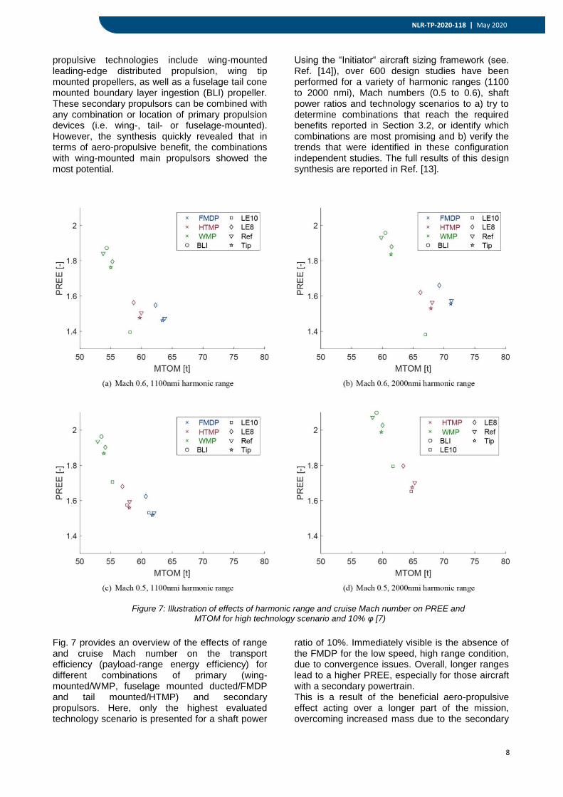
Figure 7: Illustration of effects of harmonic range and cruise Mach number on PREE and MTOM for high technology scenario and 10% φ [7)
propulsive technologies include wing-mounted leading-edge distributed propulsion, wing tip mounted propellers, as well as a fuselage tail cone mounted boundary layer ingestion (BLI) propeller. These secondary propulsors can be combined with any combination or location of primary propulsion devices (i.e. wing-, tail- or fuselage-mounted). However, the synthesis quickly revealed that in terms of aero-propulsive benefit, the combinations with wing-mounted main propulsors showed the most potential.
Using the “Initiator“ aircraft sizing framework (see. Ref. [14]), over 600 design studies have been performed for a variety of harmonic ranges (1100 to 2000 nmi), Mach numbers (0.5 to 0.6), shaft power ratios and technology scenarios to a) try to determine combinations that reach the required benefits reported in Section 3.2, or identify which combinations are most promising and b) verify the trends that were identified in these configuration independent studies. The full results of this design synthesis are reported in Ref. [13].
Fig. 7 provides an overview of the effects of range and cruise Mach number on the transport efficiency (payload-range energy efficiency) for different combinations of primary (wing-mounted/WMP, fuselage mounted ducted/FMDP and tail mounted/HTMP) and secondary propulsors. Here, only the highest evaluated technology scenario is presented for a shaft power
ratio of 10%. Immediately visible is the absence of the FMDP for the low speed, high range condition, due to convergence issues. Overall, longer ranges lead to a higher PREE, especially for those aircraft with a secondary powertrain. This is a result of the beneficial aero-propulsive effect acting over a longer part of the mission, overcoming increased mass due to the secondary

9
NLR-TP-2020-118 | May 2020
4 Boosted turbofan parallel HEP investigations by NLR
4.1 Design approach
6
propulsion system. Similarly, lower speeds make all aircraft more efficient because the propeller loading that was used was more optimal for lower cruise speed. More effort must be spent in the design of efficient propellers to fully exploit all benefits. This is very likely also the cause of the subpar performance of the configurations with 10 LE distributed propellers, especially considering the striking difference with 8 distributed propellers. Fig. 8 summarizes the resulting aircraft performance deltas with respect to a (redesigned) A320-like aircraft. It is important to note that the biggest decrease in block fuel use is due to the lower flight speed of the turboprop design (Mach 0.6) and the associated design. A further improvement is found when considering 2035 EIS improvements on engine performance. As a result any benefits/penalties of the distributed configurations with respect to the 2035 turboprop are marginal, and should be treated with caution because of the suboptimal propeller designs.
Figure 8 Illustration of block fuel (BF) changes for
different aircraft configurations and technology assumptions.
4. BOOSTED TURBOFAN PARALLEL HEP INVESTIGATIONS BY NLR
This study investigates the reduction of aircraft fuel and energy consumption, and emissions through the introduction of hybrid electric propulsion (HEP) on an Airbus A320neo. The following electric systems are considered: electric motors, batteries and power electronics. This study focusses on the parallel HEP architecture applying electric assistance to the turbofan during peak power phase, also referred to as “boosted turbofan”. The power and energy sizing of the electric components, as well as their mass effects on overall aircraft mission performance are evaluated by integrated system modelling of the aircraft, turbofan and the considered electric components. Variations of aircraft and electric component technology levels are evaluated to assess and optimize the performance of HEP. These technology levels are related to current state of the art, and the estimated state of the art in 2035. When assuming the technology level of “today” the application of parallel HEP does not show any benefit in terms of fuel or energy reduction. When assuming an estimated technology level for 2035 – including a reference aircraft with entry into service (EIS) in 2035 - reductions of fuel and total energy consumption up to 7% and 5 % respectively can be achieved when applying parallel HEP. Furthermore it is found that the minimizations of fuel burn, energy consumption, and NOx emission
counteract each other. In the 2035 scenario a compromised optimum was found, which results in 6% fuel reduction, 2% energy reduction and 1.5% NOx reduction. 4.1. Design approach
For the powertrain investigations a dedicated tool chain of parametric models for HEP performance analysis has been developed in MATLAB, see Fig. 9. This tool chain (MASS: Mission, Aircraft and Systems Simulation) simulates the performance of a specified aircraft configuration, including engines and electric systems, for a given mission. The fuel flow and electric power are calculated as function of mission time in order to predict the total trip energy consumption.
Figure 9 “MASS” tool chain for HEP performance analysis [24]
Furthermore the engine emissions are calculated. To control the HEP and electric components model the power split ratio φ is used, defined as the power supplied by the electric motors to the engine shafts divided by the total engine shaft power. A detailed description of MASS can be found in [24]. Fig. 10 depicts the performance results for an 85% scale engine, with φTO and φclimb varied between 0 and 0.4. From this figure it can be seen that mTO increases both with the increase of φTO and φclimb due to the increased electric components mass (and trip fuel mass increase in most cases). The total energy consumption (bEnergy) - relative to the EIS2035 reference a/c total energy consumption - increases with a/c weight and therefore increases with φTO and φclimb. Nevertheless a minimal value of φTO is needed in order to provide the peak power support to the downscaled engine and satisfy the TT4max constraint (maximum inlet total temperature of the high pressure turbine (HPT)). The mass of the electric motors and power electronics is mainly impacted by φTO (taking into account the peak power during take-off) whereas the mass of the batteries is mainly impacted by φclimb. Therefore the bEnergy is minimal when φclimb=0, because in this case the mass of the electric components is minimized. On the other hand increasing φclimb results in a slight decrease of the fuel consumption (bFuel). Due to the increased electric power during

10
NLR-TP-2020-118 | May 2020
4.2 Conclusion
7
climb less fuel is needed. However this effect is being reduced by the increased battery mass, increasing the required thrust and therefore increasing the fuel consumption, especially for larger φclimb values. The minimum bFuel corresponds to a φclimb value of ~0.2.
Figure 10 HEP performance results for varied φclimb
and φTO, with an 85% scale engine: (upper plots) fuel and energy consumption relative to the EIS2035
reference a/c, and (lower plots) take-off mass (mTO) and HPT inlet total temperature TT4. The red lines depict the
constraints: mTO (with “diamond” markers) and TT4 (with “star” markers).
Similar to the previous subsection the HEP performance results are also depicted for a varying engine scale, see Fig. 11, with φclimb=0. This figure shows that an engine scale smaller than 82% is unfeasible due to the TT4max constraint. Furthermore this figure shows that a minimum energy consumption can be achieved with a ~85% scaled engine, although the differences in terms of energy consumption with respect to the other engine scales are small. Generally a 5% reduction in energy consumption can be achieved with the engine scales between 82% an 90%.
Figure 11 HEP performance results for varied
engine scale and φTO, with φclimb=0: (upper plots) fuel and energy consumption relative to the EIS2035
reference a/c, and (lower plots) take-off mass (mTO) and HPT inlet total temperature TT4. The red line depicts the
TT4 constraint (with “star” markers).
Besides fuel burn and energy consumption also the engine emissions can be considered as optimization objective. Downscaling the turbofan engine decreases fuel and energy consumption but increases the NOx emission due to the increased engine temperatures. To avoid NOx emissions worse than the reference a/c the 90% scaled engine seems a better compromise than for example the 85% scaled engine. In Fig. 12 both the fuel and energy consumption and corresponding emissions are shown for a 90% scaled engine. This figure shows that the optimal performance can be found with a φclimb < 0.15 and 0.05< φTO < 0.1, depending on what performance criterion is emphasized more (fuel, energy or NOx emission).
Figure 12 HEP performance and emission predictions for varied φclimb and φTO, with a 90% scale engine relative to the EIS2035 reference a/c: (1
st row) fuel and energy
consumption,(2nd
row) mTO and TT4,(3rd
row) CO2 and NOx, and (lower plots), and (4
th row) CO and UHC. The
red lines depict the mTO constraint (with “diamond” markers) and TT4 constraint (with “star” markers).
4.2. Conclusion
A parametric system model and tool chain implementation has been developed, called MASS: Mission, Aircraft and Systems Simulation for HEP performance analysis. MASS simulates the performance of a specified aircraft configuration, including engines and electric systems, for a given

11
NLR-TP-2020-118 | May 2020
5 HEP aircraft design studies by ONERA
8
mission. The fuel flow and electric power are calculated as function of time in order to predict the total energy consumption. Furthermore the engine emissions are calculated. When assuming an estimated technology level for 2035 – including a modified A320neo reference aircraft with entry into service (EIS) in 2035 - reductions of fuel and total energy consumption up to 7% and 5 % respectively can be achieved when applying parallel HEP. Furthermore it is found that the minimizations of fuel burn, energy consumption, and NOx emission counteract each other. In the 2035 scenario a compromised optimum was found, which results in 6% fuel reduction, 2% energy reduction and 1.5% NOx reduction. 5. HEP AIRCRAFT DESIGN STUDIES BY
ONERA
In order to investigate the potential benefits of Hybrid Electric propulsion, ONERA launched in 2011 together with CEA an exploratory group composed of various systems and disciplinary experts. This initiative concluded that progress at electrical components provide new design options for aircraft propulsion systems and energy sources depending on the mission [15]. Among the solutions that have been studied, distributed propulsion was highlighted as a potential disruptive technology. Following this conclusion, ONERA launched the AMPERE project to mature distributed electric propulsion for On-Demand- Mobility applications [16]. When looking at fleet projections around 2035 [17], one can note the totally unbalanced proportion between turboprops aircraft and turbofans airplanes (5% vs 95%). There is then a market request for air transport vehicles flying above Mach 0.7. Thus, in the frame of the European Programme Clean Sky 2, within the Large Passenger Airplane platform, ONERA focuses on the development of the Distributed Electric Propulsion (DEP) for transonic cruise speed (M=0.78, the cruise speed of today’s Short and Medium Range aircraft). The main benefits expected from a Distributed Electric Propulsion is the improvement of the propulsive efficiency: through a large distribution of fans, a low Fan Pressure Ration can be maintained. Besides, the use of electric motors to drive the ducted fans limits losses due to scale (the distribution of many smaller turbofans wouldn’t be efficient [18]). Overall, the use of Hybrid Electric technology is the key enabler to achieve very high by-pass ratio solutions without the geometry constraints. Naturally, there are challenges: first, the overall electrical chain suffers from efficiency losses associated to each component. Then, the integration of the ducted fans requires thorough
studies to avoid aerodynamic degradation. Last, the distribution of important masses related to electrical systems along aircraft components has a strong impact on the primary structure that must be assessed. Thus, the assessment of Transonic Distributed Electric Propulsion requires disciplinary investigations based on high fidelity tools as well as Overall Aircraft sizing loops to assess the benefits for a given reference mission. In this paper, a summary of this multidisciplinary evaluations performed by different departments of ONERA is provided [19] |20]. The decision to aim for transonic cruise speed is clearly the design driver for the aeropropulsive configuration and thus the position of the ducted fans. After a review of design space exploration associated to different fan positions around an airfoil [21], ONERA proposed a solution characterized by ducted fans located near the trailing edge on the pressure side of the airfoil. The idea is to maintain the upper surface as clean as possible to avoid critical issues at transonic regime. Also, with such layout, the pressure side contributes to the deceleration of the flow in front of the fan inlet. Such integration would clearly interfere with the necessary common high lift devices. To answer this need, a propulsive flap concept has been proposed so that the overall layout would be efficient both in cruise and low speed conditions (see Fig. 13)
Figure 13: “Propulsive flap” concept at cruise (top) and in high-lift position (bottom)[REF]
With the key element associated to transonic DEP defined, ONERA defined an associated research aircraft concept in order to carry out in parallel different disciplinary analyses as well as overall aircraft trade studies. Defined as DRAGON (Distributed fans Research Aircraft with electric Generators by ONERA), this configuration is defined with the sole purpose of investigating as good as possible the integration of Distributed Electric Propulsion on a Large Passenger Aircraft.

12
NLR-TP-2020-118 | May 2020
9
Figure 14: “Propulsive flap” concept at cruise (top) and in
high-lift position (bottom)
With this high level objective level defined, after considering many options at configuration level for the landing gear layout (classical layout vs. tri-cycle) and the number of power generators to be installed on the airframe (2 vs. 4), the design team converged to a rather known architecture with a T-Tail and 2 power generators at the rear (see Fig. 14). With the selected empennage type, it is considered that the horizontal tail plane would be less affected by the ducted fans flow and the classical engine position would avoid additional investigations not directly associated to Transonic DEP issued. More details about the DRAGON configuration exploration can be found in [19]. As for all hybrid electric propulsion aircraft, the electric architecture is a fundamental element that profoundly affects the overall performances of the airplane. Based on early simulations, ONERA decided that DRAGON would not rely on batteries for propulsion purposes. Thus, the selected architecture is based on the distribution of electricity up to many electric motors and their associated ducted fans. This electricity is produced by 2 power generators consuming standard kerosene.
Figure 15: Distributed Electric Propulsion Architecture
featuring redundancy concepts [20]
Naturally, with DEP, the concept is to distribute the energy sources as well as the thrust generating
components. However, on an airplane, the positioning of many power generators is a challenge. For these reasons, after iterations within the design team, the configuration featuring only 2 power generators (see Fig.14 ) has been selected. After different iterations among experts, the electrical architecture evolved during the project up to its final layout featuring redundancy concepts that is presented in Fig. 15. Even if this investigation takes place at conceptual design stage, it is mandatory to include high fidelity disciplinary analyses to mature the current knowledge on DEP. Later on, information gathered through these studies are taken into account into the overall sizing tool MYSTIC [22]
Regarding aerodynamics of DEP, CFD computations have been carried out in 2D at first. During this exploratory phase, 16 designs have been tested and revised in order to finally confirm the feasibility of the proposed design. Illustrated in Fig. 16, the final 2D aerodynamic design is characterized by (i) a semi-buried ducted fan located where a spar could be found; (ii) a clean supersonic area on the upper surface; (iii) a shorter cone and nozzle geometry that prevents flow separation.
Figure 16: 2D aerodynamic design for transonic
Distributed Electric Propulsion
Following this initial step, the design team concentrated on a 3D model of the integrated design. In order to simplify CFD computations, a split in the middle of the ducted fan has been used so that the periodicity of distributed propulsion could be guaranteed. As expected, the 3D design requested specific designs in many areas, especially in the vicinity of the transition with the airfoil curvature. After the first computations, issues have been identified (high speed and separation) and taken into account in the subsequent redesigns. In Figure 17, the latest 3D design is shown.

13
NLR-TP-2020-118 | May 2020
6 Conclusion
10
Figure 17: 3D aerodynamic design for transonic Distributed Electric Propulsion (M=0.8, 35000ft)
Even if this design optimization is not completed, the first high fidelity computations show that transonic DEP is feasible without a heavy penalty on the overall aircraft lift-to-drag ratio. In the case of DRAGON, DEP is also associated to a distribution of masses along the wing span. It was then important to carry out structural sizing and aeroelastic studies to have a global understanding of this new technology and it integration on an aircraft. The method that has been implemented for the wing structural sizing is based in a Finite Element Model (FEM) and described in detail in [20]. As expected, the wing structural mass is decreased with respect to a conventional layout tailored to 2 turbofans because of the load alleviation generated by the multiple ducted fans and associated electric motors. On the other hand, the aerodynamic design as shown in Fig. 17 limits the possible wing tip deflection. Thus, parametric studies based on the wing FEM have been completed to assess the penalty in wing mass associated to this deflection.
Figure 18: Variation of wing weight for targeted wing tip
deflections
As shown in Fig. 18, such constraint might highly increase the wing weight if the allowed wing tip deflection is too small (in the current version of DRAGON, the acceptable wing tip deflection is 2.5m). For aeroelastic assessments, a 3 steps approach has been used. First, a new FEM of DRAGON is
derived based on the new structural data. In a second step, modal analyses are completed using Nastran. Last, an in-house tool is used to derive the DRAGON frequencies and dampings. This approach concluded that:
DRAGON isn’t subject to flutter problems with the given set of data;
Shifting power cables along the wing towards chord edges has a destabilizing effect;
Aeroelastic dampings are higher when there are no ducted fans in the vicinity of the wing tip.
Given these different information gathered at disciplinary level, le DRAGON concept has been refined and Fig. 19 provides an overview of this research aircraft.
Figure 19: Illustration of the research concept DRAGON showing the integration of DEP on the wing of a Large
Passenger Aircraft
As the natural next step, the sizing and assessment of DRAGON performances for a given reference mission are computed with MYSTIC [22], an ONERA internal tool. Detailed in [20], the sizing process associated takes into account various assumptions on available technologies and electrical components for an Entry Into Service in 2035. The reference mission considers a range of 2750 NM, 150 passengers divided into 2 classes and a cruise Mach number of 0.78. In order to assess the benefits of Transonic Distributed Electric Propulsion only, the design team performed also with MYSTIC the sizing of a classical configuration for the same reference mission using turbofan and new technologies also envisaged for an Entry Into Service in 2035. The preliminary results in terms of fuel consumption show that DRAGON offers a reduction of about 7% with moderate assumptions on electrical components. When comparing this technology with aircraft that entered into service in 2014, the fuel burn benefits are close to 19%. In the case of significant technological improvements [22], this improvement would be about 28%. 6. CONCLUSION
This paper provides an overview of the hybrid electric propulsion aircraft design efforts within the frame of Clean Sky2 LPA. Over the course of
14
NLR-TP-2020-118 | May 2020
7 Acknowledgement
8 Abbreviations and acronyms
9 References
11
these activities the three teams investigated various air vehicle concepts integrating novel technology bricks to identify the potential for hybrid electric flight for Airbus A320 sized aircraft. The results from of the studies indicate that HEP concepts offer potential for block fuel reduction up to about 10% for 2035 EIS aircraft. But this potential depends on many aspects like assumed specific power and energy values for electric components, the type of HEP architecture and aircraft configuration considered, and operational limitations and mission targets taken into account The studies conducted by DLR indicate benefits w.r.t. block fuel consumption in the order of magnitude of up to 3% due to the hybridization of the proposed configurations at the technology level for entry into service in 2035. Comparably low degrees of hybridization and small fractions of shaft power utilized for electrical propulsors appear beneficial. The most promising technology identified is the “boosted turbofan”. Also, advantageous synergies between the airframe layout and the propulsion system as for the BLI-Canard configuration are observed. Further investigations with higher fidelity methods are required in order to reduce the uncertainties related to the conceptual design studies. The work performed by NOVAIR focuses on both the boosted turbofan (NLR) and partial-turboelectric architectures (TU Delft). Studies of the boosted turbofan indicate that a 5% reduction in energy consumption is possible for the 2035 timeframe. This corresponds to a fuel burn reduction of 7%. Studies of the turboelectric configurations indicate that the 5% reduction in energy consumption is possible if the aero-propulsive efficiency of the aircraft is increased by 11-12%. A design synthesis exercise was performed, evaluating the effect of tip-mounted propulsion, leading-edge distributed propulsion, and boundary-layer ingestion on the turboelectric aircraft. This showed that the increase in aero-propulsive efficiency was not high enough to reach the targeted reduction in energy consumption. Nevertheless, the turboelectric configurations were found to present a similar performance to the reference aircraft even with the un-optimized geometries and assumptions made for the aero-propulsive models, for a shaft-power ratio of 10%. The ONERA study concentrated on maturing a technology that would allow hybrid electric aircraft to fly at transonic speed. The high fidelity computations enabled to focus on key areas and to have a good understanding of the different issues associated to the integrations within a Large Passenger Aircraft airframe. The first estimations made by the various experts showed potential benefits for such technology towards the reduction of aviation environmental impact. Refined studies
to be carried out in the next phase of Clean Sky 2 will help in providing more refined benefit estimations. 7. ACKNOWLEDGEMENT This project has received funding from the Clean Sky 2 Joint Undertaking under the European Union’s Horizon 2020 research and innovation programme under grant agreement No CS2-LPA-GAM-2018-01. 8. ABBREVIATIONS AND ACRONYMS
ADEC Advanced Engine and Aircraft Configuration
BF Block fuel BLI Boundary layer ingestion BTF Boosted turbofan CERAS Central Reference Aircraft data
System CPACS Common Parametric Aircraft
Configuration Schema DEP Distributed Electric Propulsion EIS Entry Into Service HEP Hybrid electric propulsion LPA Large Passenger Aircraft NOVAIR Novel Aircraft Configurations and
Scaled Flight Testing Instrumentation
OAD Overall aircraft design OEM Operational Empty Mass MTOM Maximum Take Off Mass PYC Powered yaw control RCE Remote Component Environment VTP Vertical tailplane 9. REFERENCES
1. M. Iwanizki, M. Arzberger, M. Plohr, D. Silberhorn, T. Hecken, Conceptual Design Studies of Short Range Aircraft Configurations with Hybrid Electric Propulsion, AIAA 2019-3680, AIAA Aviation 2019 Forum, 17-21 June 2019, Dallas, USA.
2. F. Mistree, K. Lewis und L. Stonis, „Selection in the Cconceptual Design of Aircraft,“ Georgia Institute of Technology, Atlanta, Georgia 30332-040, 1994
3. M. Strack, G. P. Chiozzotto, M. Iwanizki, M. Plohr und M. Kuhn, „Conceptual Design Assessment of Advanced Hybrid Electric Turboprop Aircraft Configurations,“ in AIAA 2017-3068, Denver, AIAA AVIATION Forum, 2017
4. Seider, D. (2014). Open Source Framework RCE: Integration, Automation, Collaboration. 4th Symposium on Collaboration in Aircraft Design, Toulouse, France
5. Liersch, C.M., Hepperle, M., (2011) “A distributed toolbox for multidisciplinary preliminary aircraft design”, CEAS

15
NLR-TP-2020-118 | May 2020
12
Aeronautical Journal, pp. 57-68
6. RWTH-Aachen (2017). "CERAS Central Reference Aircraft data System," Available: https://ceras.ilr.rwth-aachen.de/. Retrieved 2017
7. Silberhorn, D., Arzberger M., J., Mennicken, M., Wolters, F., Hollmann C., Iwanizki M., Multidisciplinary Investigation of Partially Turboelectric, Boundary Layer Ingesting Aircraft Concepts, AIAA Scitech 2020 Forum, USA
8. T. Hecken, X. Zhao, M. Iwanizki, M. J. Arzberger, D. Silberhorn, M. Plohr, K. Kyprianidis, S. Sahoo, S. Sumsurooah, G. Valente, M. Sielemann, C. Coïc, A. Bardenhagen, A. Scheunemann, C. Jacobs, Conceptual Design Studies of “Boosted Turbofan” Configuration for Short Range, AIAA 2020-0506, AIAA Scitech 2020 Forum. January
9. Hoogreef, M. F. M., Vos, R., de Vries, R., and Veldhuis, L. L. M., “Conceptual Assessment of Hybrid Electric Aircraft with Distributed Propulsion and Boosted Turbofans,” AIAA Scitech 2019 Forum, San Diego, CA, USA, 7-11 January 2019. doi:10.2514/6.2019-1807
10. de Vries, R., Hoogreef, M. F. M., and Vos, R., “Preliminary Sizing of a Hybrid-Electric Passenger Aircraft Featuring Over-the-Wing Distributed-Propulsion,” AIAA Scitech 2019 Forum, San Diego, CA, USA, 7-11 January 2019. doi:10.2514/6.2019-1811
11. de Vries, R., Brown, M., and Vos, R., “Preliminary Sizing Method for Hybrid-Electric Distributed-Propulsion Aircraft,” Journal of Aircraft, Vol. 56, No. 6, 2019, pp. 1–17. doi:10.2514/1.c035388.
12. Finger, D. F., de Vries, R., Braun, C., Vos, R., and Bil, C., “A Comparison of Hybrid-Electric Aircraft Sizing Methods,” AIAA Scitech 2020 Forum, Orlando, FL, USA, January 6-10 2020. doi: 10.2514/6.2020-1006.
13. Hoogreef, M. F. M., de Vries, R., Sinnige, T., and Vos, R., “Synthesis of Aero-Propulsive Interaction Studies applied to Conceptual Hybrid-Electric Aircraft Design,” AIAA Scitech 2020 Forum, Orlando, FL, USA, January 6-10 2020. doi: 10.2514/6.2020-0503.
14. Elmendorp, R. J. M., Vos, R., and La Rocca, G., “A conceptual design and analysis method for conventional and unconventional airplanes,” Proceedings of the 29th Congress of the International Council of the Aeronautical Sciences, St. Petersburg, Russia, 7-12 September 2014.14.
15 C. Döll, B. Paluch, A. Guigon , D. Fraboulet, “Conceptual feasibility study for a fully
electrically powered regional transport aircraft”, Poster session, 29th International Council of Aeronautical Sciences ICAS, 2014 (available on request).
16 J. Hermetz, M. Ridel, C. Doll, “Distributed electric propulsion for small business aircraft a concept-plane for key-technologies investigations”, 30th International Council of Aeronautical Sciences ICAS, 2016
17 T. Cooper, I. Reagan, C. Porter, C. Precourt, “Global fleet and MRO market forcast commentary 2019-2029”, Oliver Wyman, 2019
18 S. F. Yaros et al., “Synergistic Airframe-Propulsion Interactions and Integrations”, NASA/TM-1998-207644, 1998
19 P. Schmollgruber et al., “Multidisciplinary Exploration of DRAGON: an ONERA Hybrid Electric Distributed Propulsion Concept”, AIAA 2019-1585, 2019
20 P. Schmollgruber et al., “Multidisciplinary design and performance of the ONERA Hybrid Electric Distributed Propulsion concept (DRAGON)”, AIAA 2020-0501, 2020
21 A. T. Wick, J. R. Hooker and C. J. Hardin, C. H. Zeune, “Integrated Aerodynamic Benefits of Distributed Propulsion”, AIAA 2015-1500, 2015
22 S. Defoort, M. Méheut, B. Paluch, R. Liaboeuf, R. Murray, D. Mincu, J.-M. David, “Conceptual design of disruptive aircraft configurations based on High-Fidelity OAD process”, AIAA Aviation 2018, 2018
23. de Vries, R., Hoogreef, M. F. M., and Vos, R., “Aeropropulsive Efficiency Requirements for Turboelectric Transport Aircraft,” AIAA Scitech 2020 Forum, Orlando, FL, USA, January 6-10 2020. doi: 10.2514/6.2020-0502.
24 Lammen, W.F., and Vankan, W.J., “Energy Optimization of Single Aisle Aircraft with Hybrid Electric Propulsion”, AIAA Scitech 2020 Forum, Orlando, FL, USA, January 6-10 2020. doi: 10.2514/6.2020-0505.

Postal address PO Box 90502 1006 BM Amsterdam, The Netherlands e ) [email protected] i ) www.nlr.org
NLR Amsterdam Anthony Fokkerweg 2 1059 CM Amsterdam, The Netherlands p ) +31 88 511 3113
NLR Marknesse Voorsterweg 31 8316 PR Marknesse, The Netherlands p ) +31 88 511 4444
NLR is a registered trade name of Stichting Nationaal Lucht- en Ruimtevaartlaboratorium, Chamber of Commerce No. 41150373. VAT No. NL002760551B01
Royal Netherlands Aerospace Centre
NLR is a leading international research centre for
aerospace. Bolstered by its multidisciplinary expertise
and unrivalled research facilities, NLR provides innovative
and integral solutions for the complex challenges in the
aerospace sector.
For more information visit: www.nlr.org
NLR's activities span the full spectrum of Research
Development Test & Evaluation (RDT & E). Given NLR's
specialist knowledge and facilities, companies turn to NLR
for validation, verification, qualification, simulation and
evaluation. NLR thereby bridges the gap between research
and practical applications, while working for both
government and industry at home and abroad.
NLR stands for practical and innovative solutions, technical
expertise and a long-term design vision. This allows NLR's
cutting edge technology to find its way into successful
aerospace programs of OEMs, including Airbus, Embraer
and Pilatus. NLR contributes to (military) programs, such as
ESA's IXV re-entry vehicle, the F-35, the Apache helicopter,
and European programs, including SESAR and Clean Sky 2.
Founded in 1919, and employing some 600 people, NLR
achieved a turnover of 76 million euros in 2017, of which
81% derived from contract research, and the remaining
from government funds.