an overview of the new asme section viii divisin 2 pressure vessel code
DESCRIPTION
an overview of the new asme section viii division 2 pressure vessel codeTRANSCRIPT

An Overview of the New ASME Section VIII, Division 2 Pressure Vessel Code
David A. OsageThe Equity Engineering Group, Inc.
Shaker Heights, Ohio USA
API Exploration & Production Standards Conference on Oilfield Equipment and Materials
Technical Session 1: Applications of Standards Research
San Francisco, CA, June 26, 2007

2
Presentation Outline
• Introduction
• Development Objectives
• Organization
• Overview – Parts 1 through 9
• Comparison – ASME Section VIII, Div 2: 2006 vs. 2007
• Summary

3
Introduction
• To remain technically competitive, and to facilitate incorporation of new technology and future updates, ASME is developing a new pressure vessel code
• This code will replace the existing Section VIII, Division 2 Code, the first release will be July, 2007
• The new code is being developed primarily to address design and fabrication of engineered pressure vessels and will result in significant cost savings for many vessels

4
Development Objectives• Structure/Organize Section VIII considering the
following:– Division 1 – Basic Pressure Vessels (Maintenance/Enhancements)
– Division 2 – Engineered Pressure Vessels (New Code)
– Division 3 – High Pressure Vessels (Maintenance/Enhancements)
• Optimize code rules to balance technology, user-friendliness, and jurisdictional acceptance
• Develop a new organization and introduce a clear and consistent writing style to facilitate use
• Separate administrative and technical requirements
• Develop rules to facilitate computer implementation
• Incorporate PED and other international requirements
• Incorporate US Customary and Metric units

5
Organization• The table of contents for the new code incorporates a
modular flat structure to facilitate modifications and enhancements– Part 1 – General Requirements – Part 2 – Responsibilities and Duties – Part 3 – Materials Requirements – Part 4 – Design By Rule Requirements – Part 5 – Design By Analysis Requirements – Part 6 – Fabrication Requirements – Part 7 – Examination and Inspection Requirements – Part 8 – Pressure Testing Requirements – Part 9 – Pressure Vessel Overpressure Protection
• Technical information traditionally placed in Mandatory and Non-Mandatory Appendices at the back of the existing Code will be re-deployed as Annex’s to Parts in the new Code with a similar topic

6
Overview Part 1 – General Requirements
• Introduction, Organization and Definitions
• Scope and Jurisdiction
• Pressure Vessels with High Design Pressures
• Unfired Steam Boilers
• Field Assembly
• Referenced Standards
• Units of Measure, Metric and US Customary

7
OverviewPart 2 – Duties and Responsibilities
• User responsibilities
• Manufacturers responsibilities
• Inspectors duties
• Annexes on User Design Specification (UDS) and the Manufacturers Design Report (MDR)
• Separation of administrative and technical requirements, administrative requirements placed in Informative Annexes

8
OverviewPart 2 – Duties and Responsibilities
• UDS and MDR – Registered Professional Engineer (RPE) requirement– RPE certification has been in the Code since the first
issuance; however, codes and standards covering similar equipment do not require RPE certification (e.g. ASME Div. 1, ASME B31.3, API, European, etc.)
– RPE certification is unique to USA and Canada
– Industry questionnaire confirmed that RPE certification of UDS and MDR is a barrier to the use of the existing Div 2
• Alternative to the RPE certification developed -Certification of Compliance approach, certification of the UDS and MDR by the individuals in responsible charge of the design and manufacture of the vessel

9
OverviewPart 3 – Material Requirements
• New allowable stress basis will typically result in higher allowable stresses and lower wall thickness, extent of wall thickness reduction is a function of the YS/TS ratio at the design temperature
• Justification for higher allowable stresses and reduced wall thickness– Experience obtained from other PV construction codes– More stringent material requirements– Higher material toughness requirement– Better design rules– Increased NDE
• New material models for strength parameters (i.e. stress-strain curves) and physical properties provided to facilitate design and numerical analysis requirements

10
OverviewPart 3 – Material Requirements
• Modernization of toughness rules - new rules will require higher toughness, CVN=20 ft-lbs minimum
• New toughness rules based on a rigorous fracture mechanics approach– Required material toughness developed in terms of a crack
driving force based on API 579-1/ASME FFS-1, Part 9 - FAD approach, considers:
Reference flawPrimary stressResidual stress
– Required material resistance developed in terms of a required CVN, CVN will be a function of:
Material (generic type, heat treatment, yield strength)TemperatureThickness

11
OverviewPart 4 – Design By Rule Requirements
• Consolidation of design requirements for welds• New design methods
– Cylindrical and spherical shell thickness equations– Elliptical and torispherical heads (ASME Code Case 2260)– Combined loadings (pressure and net-section axial forces,
shear forces, bending moments, and torsion)– Junctions at conical transitions including junctions with a
stiffening ring and/or knuckle– Shells subject to external pressure (ASME Code Case
2286)– Evaluation of compressive stresses from combined
loadings (ASME Code Case 2286)– New nozzle reinforcement design rules for
internal/external pressure

12
OverviewPart 4 – Design By Rule Requirements
• Inclusion of existing design methods:– Layered construction– Non-circular vessels (ASME Section VIII, Div 1)– Lug-type, saddle, and skirt supports (industry accepted
procedures, e.g. Zick’s analysis for saddle supports)– Rules to evaluate vessels that are outside of tolerances
based on API 579-1/ASME FFS-1 2007, Fitness-For-Service– Expansion joints (ASME Div 1 rules)– Tubesheets (ASME Div 1 rules)
• Part 4 may be used for design of components in the creep range
• Many vessels may be designed using Part 4 without the need for design-by-analysis (Part 5)

13
OverviewPart 4 – Design By Rule Requirements
• Weld joint efficiency option introduced; the weld joint efficiency will appear explicitly in the design equations as SE, similar to Div 1
• Weld joint efficiencies – significant differences exist between the new Div 2 Code and existing ASME Codes
– Div 2, 2007 Edition – weld joint efficiencies are a function of material testing group, NDE method and extent of examination, wall thickness, welding process, and service temperature
– Div 2, 2006 Edition – 100% examination
– Div 1, 2006 Edition – weld joint efficiencies are a function of extent of examination and weld type; mixed extent of examination is permitted (RT1, RT2, RT3, and RT4)

14
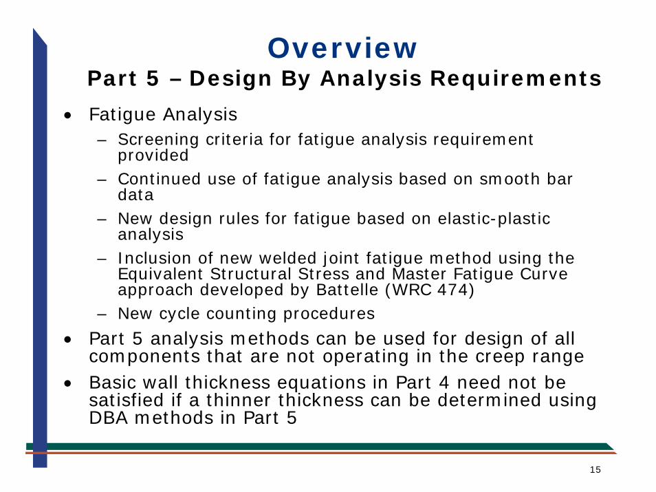
OverviewPart 5 – Design By Analysis Requirements
• Complete re-organization of Design-By-Analysis (DBA) methods based on prevention of failure modes– Plastic Collapse– Local Failure (strain limit)– Collapse From Buckling– Fatigue
• Modernization of DBA methods to accommodate advances in numerical analysis (i.e. FEA)
• Continued use of Hopper Diagram with elastic stress analysis
• Design procedures to prevent plastic collapse using limit load or elastic-plastic stress analysis based on Load Resistance Factor Design (LRFD) concepts
15
OverviewPart 5 – Design By Analysis Requirements
• Fatigue Analysis– Screening criteria for fatigue analysis requirement
provided– Continued use of fatigue analysis based on smooth bar
data– New design rules for fatigue based on elastic-plastic
analysis– Inclusion of new welded joint fatigue method using the
Equivalent Structural Stress and Master Fatigue Curve approach developed by Battelle (WRC 474)
– New cycle counting procedures
• Part 5 analysis methods can be used for design of all components that are not operating in the creep range
• Basic wall thickness equations in Part 4 need not be satisfied if a thinner thickness can be determined using DBA methods in Part 5

16
OverviewPart 6 – Fabrication Requirements
• Similar fabrication requirements to the existing Div 2
• New fabrication tolerances; if tolerances are exceeded an evaluation may be performed using API 579-1/ASME FFS-1 Fitness-For-Service
• Similar PWHT requirements are planned for the initial release; however, development of new time-temperature-thickness criterion for PWHT is under development by PVRC

17
OverviewPart 7 – Examination Requirements
• Introduction of Testing Group concept to define NDE requirements and weld joint efficiency
• Inclusion and new definition of partial radiography
– Div 1: approximately 1% coverage
– Div 2, 2007: 10% coverage
• Ultrasonic NDE may be substituted for radiographic NDE for weld examination

18
OverviewPart 8 – Pressure Testing Requirements
• New hydrostatic test pressure
• New pneumatic test pressure
• Other requirements similar to 2006 edition of Div 2
max 1.43 , 1.25 TT
SP MAWP MAWPS
⎡ ⎤⎛ ⎞= ⋅ ⋅ ⋅⎜ ⎟⎢ ⎥⎝ ⎠⎣ ⎦
1.15 TT
SP MAWPS
⎛ ⎞= ⋅ ⋅⎜ ⎟⎝ ⎠

19
OverviewPart 9 – Overpressure Protection
• Complete reorganization, utilizes the requirements of Section VIII, Div 1 by reference
• Inclusion of Code Case 2211 philosophy (system design in lieu of pressure relief)
• Update to isolation valve strategy to match what is currently in Appendix M of Section VIII, Div 1

20
ComparisonASME Section VIII, Div 2: 2006 vs. 2007
• New allowable stress basis will typically result in higher allowable stresses and lower wall thickness, extent of wall thickness reduction is a function of the YS/TS ratio at the design temperature
• Increase in allowable stress and resulting Wall Thickness Reduction (WTR) may be significant for many materials, indicator is the MYS/MTS ratio
• Consider the following comparison:
– Design pressure: 1000 psig
– Inside diameter: 60 inches
– Weld joint efficiency: 1.0

21
ComparisonASME Section VIII, Div 2: 2006 vs. 2007
Material MTS(ksi)
MYS(ksi)
Temp(°F)
S-2006(ksi)
tcyl-2006(in)
S-2007(ksi)
tcyl-2007(in)
WRT(%)
100 23.3 1.316 25.3 1.210 8
300 22.4 1.370 22.4 1.370 0
100 23.3 1.316 29.2 1.045 21
300 21.9 1.402 29 1.053 25
100 26.7 1.145 33.3 0.915 20
300 26 1.176 33.3 0.915 22
100 23.3 1.316 29.2 1.045 21
300 23.3 1.316 27.6 1.107 16
100 26.7 1.145 33.3 0.915 20
300 26.7 1.145 33.1 0.920 20
100 20 1.538 20 1.538 0
850 17.1 1.807 17.1 1.807 0
100 25 1.224 30 1.017 17
850 21.9 1.402 21.9 1.402 0
100 28.3 1.079 35.4 0.860 20
850 24.5 1.250 28.9 1.056 16SA832 GR. 22V 80 60
SA387 GR. 22 CL2 75 45
SA387 GR. 22 CL1 60 30
SA737 GR. C 80 60
SA737 GR. B 70 50
SA537 CL2, <= 2.5" 80 60
SA537 CL1, <= 2.5" 70 50
SA516 Gr. 70 70 38

22
Summary• ASME Section VIII, Division 2, 2007 has been rewritten to
incorporate the latest technology for pressure vessel design
• Alternative to RPE certification of UDS and MDR is provided
• A new allowable stress basis and toughness requirements has been incorporated
• Design-by-rule methods significantly updated to handle most of the common design requirements
• Design-by-analysis procedures have been rewritten and modernized to take advantage of the latest technologies in numerical analysis
• Examination requirements have been updated to support the new allowable stress basis
• New test pressures have been adopted
• Requirements for pressure relief design have been updated
• The new code will result in a significant wall thickness reduction when compared to earlier editions of Section VIII, Division 2

20600 Chagrin Blvd. • Suite 1200Shaker Heights, OH 44122 USA
Phone: 216-283-9519 • Fax: 216-283-6022www.equityeng.com