an xg-pon module for the ns-3 network simulator: the manual
TRANSCRIPT
An XG-PON Module for the NS-3 Network
Simulator: the ManualXiuchao Wu, Kenneth N. Brown, Cormac J. Sreenan, Jerome Arokkiam
Department of Computer Science, University College Cork, Ireland
{xw2, k.brown, cjs}@cs.ucc.ie,{jerome}@4c.ucc.ie
Pedro Alvarez, Marco Ruffini, Nicola Marchetti, David Payne, Linda Doyle
CTVR / The Telecommunications Research Centre, Trinity College Dublin, Ireland
{pinheirp, marco.ruffini, marchetn, ledoyle}@tcd.ie, [email protected]
Abstract
10-Gigabit-capable Passive Optical Network (XG-PON), one of the latest standards of optical access networks, is
regarded as one of the key technologies for future Internet access networks. This report presents our XG-PON module
for the NS-3 network simulator. This module is designed and implemented withaim to provide a standards-compliant,
configurable, and extensible module that can simulate XG-PON with reasonable speed and can support a wide range
of research topics. These include analyzing and improving the performance of XG-PON, studying the interactions
between XG-PON and the upper-layer protocols, and investigating its integration with various wireless networks. In
this report, we will introduce PON and XG-PON, discuss design principles and trade-offs made during the course,
describe the design and implementation details, and present the preliminaryevaluation results.
I. I NTRODUCTION
During the last few decades, we have witnessed the huge success of the Internet, which has changed our daily
life significantly and has become one of the main economy engines. In these years, the infrastructure of the Internet
kept evolving to provide better performance, and optical communication is one of its driving forces.
Transmission links in the network core are already based on optical fiber technology, which provides huge amount
of bandwidth through the matured DWDM (Dense Wavelength Division Multiplexing) technology. More recently,
optical fibers have also found their application in access networks to provide high speed Internet access to end users.
FTTx (Fiber To The Home/Building/Curb, etc.) networks based on Passive Optical Network (PON) technologies,
such as Gigabit-capable PON (GPON) standardized by the FullService Access Network (FSAN) group of the
International Telecommunications Union (ITU) [1] and Ethernet PON (EPON) standardized by the Ethernet in the
First Mile (EFM) task force of the Institute of Electrical and Electronics Engineers (IEEE) [2], have been widely
deployed in many countries such as the US, Korea and Japan.
2
10-Gigabit-capable Passive Optical Network (XG-PON) is a new standard released by the FSAN that improves
G-PON, by increasing the default downstream data rate to 10 Gb/s, while increasing the upstream data rate to 2.5
or 10 Gb/s. Also, the maximum number of users per wavelength is increased from 64 to 256, and amendments are
being defined for extending the physical reach up to 60 Km.
Since XG-PON could pave the way for many bandwidth-intensive applications (IPTV, Video On Demand, Video
Conference, etc.), it is very important to study the performance issues arising with the deployment of XG-PON.
For instance, it is valuable to study the impacts on the performance of XG-PON, when the propagation delay is
much longer than that of the current PON networks [3]. It is also important to investigate the interactions between
XG-PON and the upper-layer protocols (TCP [4], etc.) for improving user experience [5]. In addition, XG-PON
has been proposed for Fiber To The Cell, in which XG-PON acts as the backhaul for multiple base stations of
a cellular network [6]. Under this scenario, it is also very valuable to study its integration with various wireless
networks (LTE [7], WiMAX [8], etc.) for providing high speedmobile Internet access.
Considering that XG-PON is still in its early stage, the above research topics should be first studied through
simulation since it is too expensive to setup one XG-PON testbed and it is too complex to model the above
scenarios to be studied with enough details. In this report,we present an XG-PON module for NS-3 [9], a state of
the art open-source network simulator. Our XG-PON module isbased on a series of G.987 Recommendations from
the FSAN group of ITU. These recommendations mainly define the specifications of Physical Media Dependent
(PMD) and Transmission Convergence (TC) layers of XG-PON. To study the above research topics with reasonable
simulation speed, the optical distribution network and theoperations of physical layer are simplified significantly.
This XG-PON module focuses on the issues of TC layer, such as frame structure, resource allocation, Quality of
Service (QoS) management, and Dynamic Bandwidth Assignment (DBA) algorithms for the upstream wavelength.
During the design and implementation of this module, we havealso paid a lot of attention on its extensibility
and configurability. Since this XG-PON module needs to simulate a 10Gbps network and hundreds of ONUs, its
performance (the speed of simulation and the overhead of memory) has also been given a high priority when
designing and implementing these components.
This XG-PON module is built completely in C++ with 72 classesand approximately 22,000 lines of code.
These code are under the GNU General Public License and can bedownloaded from our websites (CTVR1 and
MISL2). To the best of our knowledge, it is the first XG-PON module for NS-3. We believe that this work is a
significant contribution to the scientific community as it allows to simulate XG-PON, the next generation optical
access network, and study the performance issues that arisewith the deployment of XG-PON.
This report is organized as follows. Section II briefly introduces PON, NS-3, and related works. The details
of XG-PON are then presented in section III. The design principles and key decisions are discussed in section
IV. The important trade-offs made by us in terms of simulation accuracy and simulation speed are also discussed
1www.ctvr.ie
2http://www.ucc.ie/en/misl/
December 18, 2013 DRAFT

3
throughout. Section V presents the details of the design andimplementation of our XG-PON module for NS-3.
The preliminary evaluation results are then presented in section VI. Finally, section VII concludes this report with
several directions for future work. At the end of this report, three appendices are also attached for introducing the
installation with NS-3, the source files, and one example of XG-PON simulation.
II. BACKGROUND AND RELATED WORK
A. Passive Optical Network (PON)
Compared to copper, optical fiber can provide higher bandwidth over a longer distance. However, the deployment
of optical fiber in access networks is severely hindered by the cost issue. In fact, optical fiber was seriously considered
for access networks only after the emergence of PON technology.
Fig. 1: An Illustration of PON
As shown in Figure 1, PON is a point-to-multipoint fiber network and there are three kinds of equipment: the
OLT (Optical Line Terminal) in central office, ONUs (OpticalNetwork Unit) in/near customer premise, and passive
optical splitters/jointers in the middle. Through splitter/jointer, OLT and the feeder fiber are shared by multiple users.
Compared with the point to point architecture, PON can significantly reduce the amount of required optical fibers
and the central office equipments. Since the passive opticalsplitters/jointers do not need power supply, the cost of
deployment, maintenance and operation can also be reduced.Thus, PON could reduce both capital expenditure and
operational expenditure significantly.
In a classical TDMA (Time Division Multiple Access) based PON network, downstream traffic is broadcast by
the OLT to all ONUs that share the same optical fiber and encryption is used to prevent eavesdropping. Upstream
traffic from ONUs is interleaved by OLT for using the optical fiber in a TDMA-like manner. Since ONUs normally
have different distances to the OLT, the data bursts from these ONUs must be scheduled carefully for providing
a collision-free and efficient upstream data communication. To accommodate the dynamics in bandwidth demands
from users and exploit the gain of statistical multiplexing, dynamic bandwidth assignment (DBA) is normally used
December 18, 2013 DRAFT

4
for managing the upstream bandwidth. More specifically, ONUs will report their buffer occupancy to OLT, which
will then allocate the upstream bandwidth to ONUs based on their bandwidth demands and their Service Level
Agreement (SLA).
Some standards have been developed for PONs by both EFM of IEEE (EPON) and FSAN of ITU-T (GPON).
EPON is designed for carrying Ethernet frames and GPON can carry various traffics through encapsulation, such as
Ethernet frames and ATM cells. Although EPON and GPON have different frame structures, they share the same
network architecture and data communication follows the same principles described above. One important difference
between EPON and GPON is that GPON is well standardized for QoS management. Hence, GPON can provide
full service with the same network and it is highly preferredby ISPs. XG-PON is the new standard developed by
FSAN based on GPON. Its details will be introduced in sectionIII.
B. NS-3 Network Simulator
NS-3 [9] is a state of the art open-source network simulator.Based on many lessons from the well-known
NS-2 simulator [10], NS-3 is written from the scratch and it is a completely new network simulator. NS-3 has
many attractive features, such as high emphasis on conformance to real networks, good support for testbeds, a
novel attribute system for configuring simulation parameters, automatic memory management, and a configurable
tracing system [11]. It has also been reported that NS-3 performs much better than other simulators in terms of
simulation speed and memory overhead [12]. The first releaseof NS-3 was made in June 2008 with support for
a number of modules including CSMA, Point-to-Point, WiFi (IEEE 802.11), TCP, UDP and IPv4. Figure 2 shows
the organization of NS-3 modules.
Fig. 2: The Organization of NS-3 Modules
In the last few years, many new modules have been developed and added into NS-3, such as WiMAX module
from Inria [13] and LTE module from CTTC [14]. Thus, through implementing one XG-PON module in NS-3, we
December 18, 2013 DRAFT

5
can get a very good research platform for studying the issuesarisen with the deployment of XG-PON.
C. Related Work
Although simulation has been used to study PON, the existingwork cannot be used directly or extended easily
to study the performance issues arising with the deploymentof XG-PON.
In [3], the authors developed their own simulator to study dynamic bandwidth assignment (DBA) algorithms
when the physical reach is much longer than the current PON networks. This simulator has limited functions and
there is no Internet protocol stack, which is needed to studymany research topics.
EPON and GPON had also been studied with OPNET [15] and several models have been implemented by different
groups [16][17]. However, these EPON/GPON models are not available to the public. Furthermore, OPNET simulates
too many details (CPU of a router, etc.) and the simulation speed is slow even when the simulated network bandwidth
is lower than 1 Gb/s. Since OPNET is not an open-source simulator, we cannot change its core to simulate a 10
Gb/s XG-PON network with a reasonable simulation speed.
In addition, one simple EPON module has been developed for OMNeT++ [18] and the code is available to the
public. Since there are a lot of difference between EPON and XG-PON, the code of this EPON module may not
be very helpful to implement one XG-PON module for OMNeT++. Considering the good points of NS-3 discussed
above, it should be better to develop one XG-PON module from the scratch for the NS-3 network simulator.
Hence, an XG-PON module is designed and implemented in this report for NS-3. With such an XG-PON module,
we can simulate XG-PON and study its own performance. With the more realistic Internet protocol stack of NS-3,
we can study the performance experienced by users/applications in XG-PON networks. With the existing NS-3
modules for various wireless networks (WiFi, WiMAX, LTE, etc.), we can also study the integration between
XG-PON and wireless networks, which is the trend of the future Internet access networks. In summary, with this
XG-PON module, NS-3 will become a good platform for studyingthe next generation Internet access networks
composed by XG-PON and wireless networks.
Not only XG-PON, we can also extend this XG-PON module to study Long-Reach PON (LR-PON), an evolution
of XG-PON with a larger number of users, symmetric data rate (10 Gb/s in both upstream and downstream), and
longer reach (100+ km) [19][20]. The aim of our LR-PON research group is to initially build LR-PON from the
XG-PON standard, while identifying the required modifications and improvements.
III. XG-PON DETAILS
The XG-PON standard has many similarities with GPON, such asits TDMA scheme used to share the medium,
the mechanism to provide QoS, and the DBA scheme used for the upstream wavelength. However, some changes
are required in order to support a larger number of users, higher data rate, and extended physical reach. In this
section, we will present the details of XG-PON.
December 18, 2013 DRAFT

6
A. Overview of XG-PON
A series of recommendations has been released by FSAN of ITU-T for XG-PON. ITU-T G.987 explains several
important concepts of XG-PON and ITU-T G.987.1 presents thegeneral requirements, such as network architecture,
migration and coexistence with GPON, services to be supported, hardware specifications, protocol stack, etc. ITU-
T G.987.2 focuses on issues of the physical media dependent (PMD) layer, such as the used wavelength and the
supported data rates. ITU-T G.987.3 presents the details oftransmission convergence (TC) layer. Not only the
protocols for data communication, it also covers QoS management and Dynamic Bandwidth Assignment (DBA)
scheme for the upstream wavelength. Another related recommendation is ITU-T G.988, which specifies ONU
management and control interface (OMCI) for both GPON and XG-PON. Figure 3 illustrates XG-PON common
functions and the recommendations in which they are specified.
Fig. 3: XG-PON common functions
B. Network Architecture
XG-PON has been proposed for various deployment scenarios to serve different customers, such as residential,
business, and cell site. To serve these customers, XG-PON lists the services to be provided, such as Telephony, high
speed Internet access, mobile back-haul, etc. XG-PON also introduces many ONU variants that provide different
functions and interfaces. In summary, XG-PON has been well standardized for providing full services to various
users with one optical network.
December 18, 2013 DRAFT

7
Fig. 4: XG-PON Network Architecture
As for optical distribution network, XG-PON can be deployedas a classical PON, but mechanisms to extend its
reach up to 60 km are currently being defined. As illustrated in Figure 4, to support this longer physical reach, active
component (Reach Extender) can be applied in remote nodes and one XG-PON can be composed of multiple passive
segments connected through REs. These REs can be optical amplifiers or optical-electrical-optical regenerators that
could fulfill the necessary optical link budget.
C. PMD Layer
There are two flavours of XG-PONs based on the upstream line rate: XG-PON1, featuring a 2.5 Gb/s upstream
path, and XG-PON2, featuring a 10 Gb/s one. The downstream line rate is 10 Gb/s in both XG-PON1 and XG-PON2.
ITU-T G.987.2 focuses on the PMD layer for XG-PON1. XG-PON2 hasn’t been standardized yet.
In XG-PON1, the used wavelengths are 1575-1580nm (downstream) and 1260-1280nm (upstream). The exact
downstream line rate is 9.95328 Gb/s and the upstream one is 2.48832 Gb/s. For line coding, NRZ (Non-Return
to Zero)is used for both directions. ITU-T G.987.2 also specifies the requirements for hardwares, such as optical
fiber, transmitter/receiver, etc.
D. Transmission Convergence Layer
The XG-PON Transmission Convergence (XGTC) layer is where the Medium Access Control (MAC) protocol
of XG-PON are defined.
To carry traffic between the OLT and the ONUs, the XGTC layer maintains logical connections between these
two entities, designated XGEM Ports. Each connection is identified by a unique XGEM Port-Id, which enables to
send a packet to the correct ONU and associate a connection toa certain Quality of Service (QoS) agreement. Note
that one connection is configured to carry downstream or upstream traffics. It’s impossible for two connections in
the same direction (downstream or upstream) to have the sameXGEM Port-Id, but one downstream connection
may use the same XGEM Port-Id with one upstream connection. To reduce the overhead of the DBA scheme,
December 18, 2013 DRAFT

8
upstream bandwidth is allocated to groups of connections belonging to a single ONU. These groups are designated
as Transmission Containers (T-CONT) and each group/T-CONTis identified by a unique identifier, the Alloc-Id.
Figure 5 shows the multiplexing in XG-PON for both directions.
(a) Downstream (b) Upstream
Fig. 5: Multiplexing in XG-PON
XGTC comprises three sublayers: service adaptation, framing, and PHY adaptation, from top to bottom. Following
these sublayers, XGTC is introduced below.
1) Service Adaptation Sublayer:The service adaptation sublayer is responsible to adapt theupper layer traffic
to the transmission mechanisms of XG-PON. It will do this by mapping upper layer traffic to the correspond-
ing connections, encapsulating/decapsulating data, segmenting/reassembling SDUs when necessary and inserting
padding when there is not enough data to fill an XGTC frame. If needed, it is also this sublayer’s responsibility to
encrypt/decrypt SDUs.
To map upper layer data to and from the connections of XGTC layer, the OLT will maintain all connections and
the ONU will maintain the connections that belong to itself.
When the upper layer has something to transmit, it is also the service adaptation sublayer’s responsibility to select
the connections to be served according to their QoS parameters. When a connection is scheduled to be served, the
service adaptation sublayer will then get data from its queue and insert an XGEM header to create an XGEM frame.
The XGEM header will contain an XGEM Port-Id and some other information related to segmentation, padding,
encryption, etc.
When receiving an XGEM frame, the service adaptation sublayer will get the XGEM Port-Id from the XGEM
header. If the corresponding connection exists in the connections maintained by the OLT/ONU, this sublayer will
carry out reassembly (if necessary) and pass the data to upper layer. Otherwise, this XGEM frame will be discarded.
December 18, 2013 DRAFT

9
2) Framing Sublayer:In XG-PON, the OLT will send downstream XGTC frames every 125µs, to broadcast
traffic to all ONUs. In the upstream, ONUs send variable length XGTC bursts to the OLT for their upstream traffic.
The length and start time of these upstream bursts are determined by the OLT through a DBA algorithm.
The framing sublayer is responsible to generate and parse these XGTC frames/bursts. When generating one
downstream XGTC frame at the OLT, the framing sublayer gets XGEM frames from service adaptation sublayer
and joins them together into an XGTC payload. To create an upstream XGTC burst at ONU side, the framing
sublayer may create multiple XGTC payloads, where each payload will carry XGEM frames from a single T-
CONT. When parsing an XGTC frame/burst, the framing sublayerwill send its payloads to the service adaptation
sublayer for further processing.
In the header of the upstream XGTC burst generated by an ONU, there might be queue occupancy reports for
the T-CONTs of this ONU. For each downstream XGTC frame, its header contains one BWmap, which instructs
ONUs to share the upstream wavelength in a TDMA-like manner.More specifically, BWmap specifies the size of
bandwidth allocations for T-CONTs, the used burst profile (the length of preamble, the length of delimiter, forward
error correction or not, etc.), and the time to start to transmit. Since the OLT-ONU physical distance could be quite
different for ONUs, each ONU should adjust the start time foravoiding collision in the upstream direction. Note
that when one ONU is activated, the ranging procedure is carried out between the OLT and this ONU to determine
how to adjust the start time of its upstream bursts. Figure 6 illustrates the time-lines in XG-PON. The OLT and
ONUs have a common view of the logic one-way delay of the optical distribution network (the largest one-way
propagation delay plus various processing delay) and each ONU uses its own equalization delay (EqD calculated
in ranging procedure) to avoid collisions in upstream direction.
Fig. 6: Time-line in XG-PON
In the header of one upstream XGTC burst, the ONU can send one PLOAM (Physical Layer Operations,
Administration and Maintenance) message to the OLT. As for one downstream XGTC frame, the OLT can send
multiple PLOAM messages to multiple ONUs. Through exchanging PLOAM messages, many XGTC functions
December 18, 2013 DRAFT

10
(key management, ONU power management etc.) can be fulfilled.
3) PHY Adaptation Sublayer:PHY adaptation sublayer interacts with PMD layer directly.Its main functions
are forward error correction (FEC), scrambling, and frame delineation through a Physical Synchronization Block
(PSB). In the downstream, the PHY adaptation sublayer will get an XGTC frame to create a PHY frame. These
PHY frames are sent continuously every 125µs. In the upstream, the PHY adaptation sublayer will get the XGTC
burst and create a PHY burst. These PHY bursts have variable length due to the variable-length XGTC bursts. In
the PHY burst, the PSB is determined by a burst profile selected by the OLT (through the BWmap) among the
burst profiles, that are configured through PLOAM messages.
Figure 7 illustrates how these sublayers encapsulate the SDUs of XG-PON into 125µs the downstream frames
or the variable-length upstream bursts.
(a) Downstream (b) Upstream
Fig. 7: SDU Mapping in XG-PON
E. Scheduling and DBA
To decide the data to be transmitted in a downstream XGTC frame, a downstream scheduler is used by the OLT.
Based on QoS parameters and service history of these downstream connections, the downstream scheduler will
decide the connections to be served and the amount of data to be transmitted for each of them.
As for the upstream scheduling, the OLT uses a DBA algorithm to allocate the upstream bandwidth to T-CONTs.
The DBA algorithm makes decisions based on queue occupancy reports, QoS parameters, and service history of
these T-CONTs. The DBA algorithm needs to select the T-CONTsto be served, reserve a short gap time between
the consecutive XGTC bursts for tolerating clock synchronization errors, determine the size of each bandwidth
allocation, and calculate the start time for each bandwidthallocation. These decisions are broadcast to ONUs
through BWmap. Since the upstream bandwidth is allocated to T-CONTs and each T-CONT may have multiple
December 18, 2013 DRAFT

11
upstream connections, the ONU also needs one upstream scheduler to determine the upstream connections to be
served during one transmission opportunity assigned to oneT-CONT.
These scheduling algorithms, especially the DBA algorithm, are very important to network performance and
QoS management. To allow competition and encourage research, these algorithms were intentionally left out of the
standard. Indeed, it has been a very hot topic to study DBA algorithms for EPON and GPON [21][22][3]. Hence,
there should be many research opportunities for XG-PON too.
IV. D ESIGN PRINCIPLES AND KEY DECISIONS
When designing and implementing XG-PON module, there are many issues to be considered and many tradeoffs
must be made when the goals conflict with each other. This section will present the design principles followed by
us and the key decisions make during the course.
A. Design Principles
• Standard Compliance:
The ultimate goal of our research is to improve the performance issues arisen with the deployment of XG-PON.
It is highly desirable that the simulated XG-PON is close to the real XG-PON networks that will appear in
the future. We can then identify the real problems and provide solutions that can be directly applied in the
real world. Hence, we will follow G.987 Recommendations from the FSAN group of ITU when designing this
XG-PON module.
• Simplicity:
Considering that XG-PON is a quite complex standard, it willtake a very long time to simulate the whole
network, from physical layer to network management. For instance, the document for ONU Management and
Control Interface (G.988) is more than 500 pages. Hence, we must decide the functions to be simulated in
current phase. We will only simulate the functions needed byour research. Other functions will be left alone
or designed as some stub classes for the future extension. For instance, since we are mainly interested in
XGTC layer and upper layer issues, we can simulate the physical layer in a very simple way. We can assume
that power budget for the optical distribution network has been satisfied through various techniques. The reach
extenders and passive optical splitters/jointers need notbe simulated. The channel, that simulates the optical
distribution network of XG-PON, can simply pass downstreamframes to all ONUs and pass upstream bursts
to the OLT. As for Forward Error Correction (FEC), instead ofthe algorithm itself, we can simulate only its
effect, i.e., the bandwidth overhead and the much lower packet corruption rate.
• Extensibility:
When designing the XG-PON module for NS-3, we should also consider its extensibility since many other
research topics might also be studied using this module. Hence, the extensibility is very important. When
designing the class architecture of the XG-PON module, abstract class should be used appropriately and the
interface should be well designed for the future implementation that simulates more details. Of course, we will
December 18, 2013 DRAFT

12
only provide a much simpler implementation for the components that we are not interested in current phase.
For instance, when designing the class interface for the channel that simulates the optical distribution network
of XG-PON, we should enable researchers to specify the tree structure of fibers, reach extenders, and splitters.
When adding one ONU, they can also specify the splitter that itwill be attached and the physical distance
between them. With this interface, it is possible to simulate the optical signal propagation and the possible
packet corruption. However, for the current phase, we can let the channel store a list of ONUs and pass the
downstream frames to all of them (without any error)3. Since DBA algorithm is one hot research topic, the
classes for DBA should be well designed to allow the easy implementation of various DBA algorithms.
• Configurability:
In one simulated XG-PON network, there could be thousands ofnodes, such as the OLT, hundreds of ONUs, and
hundreds of data traffic generators/sinks in core networks.Many nodes will also be attached to ONUs through
various networks and act as traffic generators/sinks. We should export many configurable parameters, but
provide default parameters for most of them. Other methods should also be considered to easy the researcher’s
task for configuring the XG-PON network to be simulated.
• Simulation Speed:
Considering the XG-PON to be simulated is a 10Gbps network, simulation speed must be considered in all
times. One module, that can simulate XG-PON accurately (butvery slowly), is useless for our research in
which extensive simulations are needed. We should select the data structures and algorithms carefully for saving
CPU and memory. For instance, when XG-PON is fully loaded andthe size of each packet is 1KBytes, the
simulator need process around one million packets per second. Since XG-PON could have hundreds of ONUs
(1023 at most), the simulator must run the procedure used by ONU to judge whether it is the destination
of one XGEM frame one billion times per second. This procedure must be implemented high-efficiently.
Straightforwardly, we can add one vector at each ONU whose index is XGEM Port-Id. When configuring
XGEM Ports for this ONU, this vector can be marked correspondingly. Consequently, this vector can be used
to filter out the traffic for this ONU quickly. However, XGEM Port-Id is a 16-bit number and this vector can
consume a lot of memory when the number of ONU is large. Due to the same reason, hash map in which
GEM Port-Id acts as the key is not adopted by us too. In our XG-PON module, we impose some simple
relationship among XGEM Port-Id, Alloc-Id, ONU-ID, and IP address of the computer that this XGEM Port
belongs to. Consequently, we consume a small amount of memory in total and achieveO(1) time complexity
when mapping IP address/XGEM Port-Id to the corresponding data structure.
During the implementation, many useful features of C++ language should be exploited and some black-holes
of CPU cycles should be avoided. First, we should pass parameters by reference whenever it is possible and
const reference is preferred. We should also know that the smart pointer provided by NS-3 is fundamentally
3Depending on the situation, it may be worthwhile to simulate a likely packet corruption rate, which should be very low with considering
the effects of FEC.
December 18, 2013 DRAFT

13
a small object. When the function is called frequently and some of its parameters are smart pointers, we
should replace them with the reference of that smart pointer. Second, since C++ allows one class to override
its new anddeleteoperators, we should exploit this feature for data structures that are created and destroyed
dynamically and frequently. Through overriding the two operators, we can avoid to call the expensivemalloc
too many times and CPU cycles can be saved. Third, when we select the data structure for a sequence of
objects,vectorshould be considered due to its efficiency. However, when toomany objects are added into one
vector, reallocation may occur and the simulation can be slowed down significantly. Thus, we should reserve
enough memory if the largest vector size can be pre-determined. Otherwise,dequeshould be considered as
the container. Fourth, although virtual function and inheritance are very attractive, they should be used when
absolutely necessary since virtual function is much slowerthan the common function. Class downcast should
also be avoid in the implementation since it is unsafe and consumes a lot of CPU cycles. For instance, for
each function of XGPON (DBA, etc.), there should be two classes designed for OLT and ONU, respectively,
and it is attractive to let them inherit from the same parent.However, the logic at OLT is totally different with
that of ONU, the amount of reused code is limited, the interface of the parent becomes more complex, and
simulation speed is slowed down. Thus, these classes are designed independently and the inheritance is not
used.
B. Key Decisions
Below are several key decisions made by us when designing andimplementing this XG-PON module.
• Stand-alone Simulation: Since XG-PON is a 10Gbps network with hundreds of ONUs, it is very attractive
to use distributed simulation to speed up XG-PON simulation. However, although NS-3 supports distributed
simulation through MPI, this feature only works for point-to-point links and XG-PON is fundamentally a
point-to-multipoint network. Many works are necessary to enable distributed simulation for XG-PON and we
need also study how to allocate ONUs to different computers.Furthermore, many researchers may not have
the access to some clusters and these clusters may not support MPI well. Thus, in the current phase, this XG-
PON module works as a stand-alone simulator. It uses only onecore even when one computer has multiple
processors or cores. In the future, distributed simulationwill be considered for this XG-PON module.
• Packet-level Simulation: Due to the high bandwidth of XG-PON (10Gbps) and the frequency of state-of-the-art
processor (several GHz), it is hopeless to simulate the details in byte or bit level. For flow-level simulation,
it’s too complex to model both XG-PON and TCP/IP protocol stack, and We cannot study the potential subtle
interactions between TCP/IP and XG-PON. Considering that NS-3 is fundamentally a packet-level simulator,
this XG-PON module should simulate XG-PON in packet level. Furthermore, when passing traffic between
OLT and ONU, all XGEM frames in the downstream frame or upstream burst should be handled together, and
the number of simulation events can be reduced significantly. Due to the short XG-PON frame size (125µs),
the upper layer protocols won’t be affected if we keep the order of XGEM frames in the downstream frame or
the upstream burst. Based on this decision, many physical layer operations, such as line coding and Forward
December 18, 2013 DRAFT

14
Error Correction, will not be implemented in this module. However, the bandwidth overhead of FEC must be
considered. Payload encryption/decryption will not be implemented too. The logic used for key management
will be implemented for future extensions.
• XG-PON in Operation: Since we are mainly interested in the performance issues of one XG-PON network in
operation, many aspects of XG-PON can be simplified. For instance, the activation procedure that uses PLOAM
messages to add one ONU to one operating XG-PON need not be implemented. We can simply add all ONUs
to the network before starting the simulation through one helper class. Instead of the ranging procedure that
uses PLOAM messages to measure the one-way propagation delay of each ONU, we can set the same value
to both the OLT and this ONU when configuring the XG-PON to be simulated. In XG-PON, XGEM Port
and T-CONT configuration is carried out through OMCI (ONU Management and Control Interface: G.988).
However, this standard document (more than 500 pages) is very complex and it will take a lot of time to
implement OMCI for XG-PON. Thus, instead of configuring XGEMPort and T-CONT dynamically through
OMCI, we will configure all XGEM Ports and T-CONTs before starting the simulation through one helper
class. In summary, PLOAM and OMCI channels will not be fully implemented in this XG-PON module. Stub
classes will be designed for the future extensions.
• Simple Optical Distribution Network and Reliable Data Transfer: In XG-PON, the optical distribution network
is quite complex and is comprised of many optical fibers, splitters/jointers, and reach extenders. Although they
are important to network architecture and optical device research, they are irrelevant to the research topics that
we plan to study. Thus, the optical distribution network will be modeled as one simple channel and we only
simulate the propagation delay and line rates. We assume that the link power budget has been ensured through
various techniques (reach extenders, etc.) and the laser receiver can work well. Thus, we won’t simulate optical
signal propagation (wavelength-dependent) and assume that all downstream frames and upstream bursts can
arrive to their recipients correctly. In another word, transmission errors are not simulated in our XG-PON
module. This is reasonable since FEC is normally applied to hide transmission errors. Based on this decision,
CRC and HEC (header error correction) are not executed in thesimulation.
In the future, transmission error might be simulated. At therecipient, the downstream frame or upstream burst
will be dropped with a distance-dependent probability. This is reasonable since FEC is normally used and there
is no XGEM frame delimitation. Once the transmission error cannot be handled by FEC, all of the following
data cannot be decoded by the recipient.
• Serialization Avoidance and Meta-data in Data Structures:Since this XG-PON module is designed for stand-
alone simulation, (de)serialization is unnecessary and should be avoided4. This is why XgponXgemFrame is
added into this XG-PON module to represent XGEM frame. At thefirst glance, we can use Packet provided by
NS-3 directly. XGEM frame header can be added into and extracted from Packet easily. Packet also supports
4Of course, all data structures should provide one function to return its Serialized size for composing the downstream frame and upstream
burst correctly.
December 18, 2013 DRAFT
15
fragmentation and reassembly which is needed by XGEM encapsulation. However, when XGEM frame header
is added into Packet, the header is serialized and put into one byte array. When one XGEM frame is received,
the recipient needs to extract the XGEM frame header from thebyte array, i.e., create one XgponXgemHeader
and carry out de-serialization. Considering that one XGEM frame in downstream direction will be processed by
hundreds of ONUs, the above operations may consume too much CPU. To solve this issue, XgponXgemFrame
is designed to have one smart pointer of XgponXgemHeader andone smart pointer of the corresponding SDU
(an instance of Packet). At the recipient, it can then get XgponXgemHeader directly from XgponXgemFrame.
Another observation is that some meta-data can be added intodata structures for various purposes since they are
exchanged between OLT and ONU as objects (instead of a byte array). For instance, all XGEM frames of one
downstream frame need be checked by all ONUs and it is very expensive when the number of ONUs is large.
We notice that due to the small size of the downstream frame and the bursty bandwidth allocation, the traffic
in one downstream frame might belong to a few ONUs. Thus, a bitmap can be added to the downstream frame
to indicate whether one ONU needs to check XGEM frames in thisdownstream frame. With this meta-data,
the simulation can be speed up significantly when there are many ONUs in the simulated XG-PON network.
• Extensible DBA, Scheduling, and Queue Schemes:
As discussed in subsection III-E, downstream scheduler at the OLT is responsible to allocate the downstream
bandwidth to the downstream XGEM Ports. DBA at the OLT is responsible to allocate the upstream bandwidth
to T-CONT, and upstream scheduler at ONU is responsible to allocate the transmission opportunity of one
T-CONT to the upstream XGEM Ports. These algorithms and the queue used by each XGEM Port at the sender
side are very important to the performance of the whole network and the QoS experienced by user traffic. In
this XG-PON module, these classes will be designed carefully to support future extensions. New algorithms
should be implemented easily through inheriting these classes and instantiating a few functions.
In summary, this XG-PON module can be used to carry out stand-alone packet-level simulations for studying
XG-PON networks in operation. Table I summarizes how XG-PONfunctions are supported in this XG-PON module.
December 18, 2013 DRAFT

16
Function Layer Simulated? Comments
Optical Distribution Network & PMD X Use one simple channel to simulate ODN.
Signal Propagation & We only simulate propagation delay and bandwidth of the channel.
Line Coding & Frame Detection These information will be provided to other classes of this module.
Burst Profile PMD√
Instead of OMCI, they are configure through helper class.
FEC & Scrambling PHY ad X Just provide FEC overhead information to other classes.
XGTC Framing Framing√
HEC and CRC is not implemented for saving CPU.
PLOAM Engine Framing√
Just implement the logic and interface for exchanging messages.
DBA & QoS Framing√
Round-robin is implemented first.
DS Scheduling & QoS N/A√
In the first phase, Round-robin will be implemented.
US Scheduling & QoS N/A√
Round-robin will be used for XGEM Ports of one T-CONT.
XGEM Framing Service ad√
HEC isn’t implemented.Fragmentation and reassemblingare implemented.
Encryption Service ad X Not implemented. Key management logic will be implemented.
(De)Multiplexing Service ad√
Packet classification and flow management are implemented.
Alloc-Id, XGEM Port-Id, and IP address are assigned carefully for speed.
Queue Mechanism Service ad√
one FIFO queue per XGEM Port
OMCI & MIB N/A X Configuration will be carried out through helper class.
Activation & Ranging N/A X Not implemented. Per-ONU delay is configured through helper class.
TABLE I: Choices for Simulating XG-PON in NS-3
December 18, 2013 DRAFT

17
V. THE XG-PON MODULE FORNS-3
This section describes in detail the XG-PON module we have developed for NS-3. Our aim is to provide a
standard compliant, configurable, and extensible module that can simulate XG-PON with reasonable speed and can
support a wide range of research topics.
A. Overview of the XG-PON Module
Fig. 8: The Reference XG-PON Simulation
Figure 8 illustrates a typical simulation that uses this module and NS-3 to study the performance issues arising
with XG-PON. The OLT is simulated as a node that has oneXgponOltNetDeviceand another network device,
such as PointToPointNetDevice, to connect to an external network. The ONU is simulated as a node with one
XgponOnuNetDeviceand other network devices (Ethernet, WiFi, WiMAX, LTE, etc.) for connecting user equipments
to the ONU. Thanks to NS-3, network devices of a node can be configured and we can study different deployment
scenarios of XG-PON easily. Although XG-PON is proposed to carry layer-2 frames of various network technologies
(Ethernet, ATM, etc.), our XG-PON module interacts directly with the IP layer and IP packets are the SDUs. This
is reasonable since we focus on FTTx networks connected to the Internet.
The OLT and ONUs are attached toXgponChannelthat simulates the optical distribution network (ODN) of
XG-PON. As illustrated in Figure 4, this ODN is a quite complex tree composed by optical fibers, splitters/jointers,
and REs. To produce trustworthy simulation results, it is highly desirable to simulate all details. However, XG-PON
is a high speed network with a very complex standard. In this module, many aspects have been simplified for
reducing the development workload and speeding up the simulation speed.
Specifically, our XgponChannel just simulatesdmax, i.e., the logic one-way delay of the channel that is determined
by the maximal propagation delay of ODN and various processing delay.dmax can be configured through the
December 18, 2013 DRAFT

18
attribute system of NS-3. For a downstream frame from the OLT, XgponChannel will pass this frame to each ONU
after waiting ford, i.e., the corresponding one-way propagation delay between the OLT and this ONU. Note that
for avoiding unnecessary data copy, XgponChannel passes the smart-pointer of this frame to each ONU which will
just copy and process the data for itself5. As for an upstream PHY burst, it will be postponed for the corresponding
propagation delay, but XgponChannel will pass it to the OLT only. The equalization delay is considered by ONU
when it schedules to produce the upstream burst based onBWmap from the OLT.
This means that although the difference of propagation delay among ONUs is simulated, the propagation of
optical signals (fiber, splitter, etc.) is not simulated by the XgponChannel. This design is reasonable since the
targeted research topics are related with MAC and upper layers. Through these simplifications, simulation speed
can also be significantly improved. Otherwise, many events must be scheduled to pass a downstream XGTC frame
to ONUs if fibers and splitters are considered. It is also veryCPU-intensive to calculate the optical signal strength
for each downstream frame when it arrives to each ONU.
In the following subsection, we will present how the XG-PON protocol stack is simulated. More specifically, we
will identify its functional blocks, followed by the designand implementation details.
B. XG-PON Functional Blocks
Since we are interested in the performance of a running network, the functional blocks of XG-PON are identified
below through explaining the data transmission paths in both downstream and upstream directions.
1) Downstream Traffic on OLT Side:As shown in Figure 9, when one SDU is received from the upper layer,
it will first be mapped to the corresponding connection (XGEMPort) based on the destination IP address and put
into the queue for transmitting in the future. Thus, there must be one algorithm for mapping the IP address to a
XGEM Port-Id.
Since the OLT needs to broadcast the downstream XGTC frames every 125µs, it will periodically ask the OLT’s
Framing Engineto generate a XGTC frame. This engine will first generate an XGTC header since the available
space for data in the frame depends on the size of the XGTC header.
For the payload of a downstream XGTC frame, the Framing Engine resorts to theXGEM Engineto get an
XGTC payload. This payload is comprised of concatenated XGEM frames that occupy all the available space. As
for the SDUs to be encapsulated and transmitted, the XGEM Engine lets theDownstream Schedulerdecide the
connections to be served. This scheduler makes decisions based onDownstream Connection Managerwhich knows
queue length, QoS parameters, and service history of each downstream connection. When carrying out encapsulation,
fragmentation will be carried out by XGEM Engine if one SDU istoo long for the current transmission opportunity.
XGEM Engine is also responsible to encrypt these SDUs to avoid eavesdropping. The keys used for data encryption
are negotiated through PLOAM messages and are maintained byPloam Engine.
5In the future, this feature will be revised to support parallel simulation in which ONUs are simulated on different CPUs of acluster.
December 18, 2013 DRAFT

19
Fig. 9: Function Block Diagram of XG-PON
To construct the XGTC header of the frame, theDBA Engineis used to generate BWmap that tells ONUs how to
share the upstream wavelength. DBA Engine makes decisions based on queue occupancy reports, QoS parameters,
and service history of T-CONTs. As for the PLOAM messages in the header, they are generated by Ploam Engine.
The downstream frame is sent to the ODN after passing throughPHY Adaptation EngineandPMD Engine.
2) Downstream Traffic on ONU Side:When a downstream PHY frame arrives to one ONU, it will pass through
PMD Engine and PHY Adaptation Engine which will remove the physical-layer overhead. The Framing Engine is
then responsible to parse the resulting downstream XGTC frame.
The PLOAM messages from the XGTC header will be given to the Ploam Engine, which will process the
messages related with this ONU. The DBA Engine is responsible to process BWmap in the header, i.e., schedule
December 18, 2013 DRAFT

20
its upstream XGTC bursts if required by this BWmap.
As for the payload, the XGEM frames are passed to XGEM Engine.Based on the list of its connections maintained
by Downstream Connection Manager, the XGEM frames for this ONU are first extracted. XGEM Engine then carries
out decapsulation, decryption, and reassembly (if needed)6. The received SDUs are then sent to the upper layer.
3) Upstream Traffic on ONU Side:As illustrated in Figure 9, when a IP packet is received at theONU, based
on the source IP address, it is first mapped the correspondingupstream connection that are organized byUpstream
Connection Manager. The packet is then put into the corresponding queue for transmitting in the future.
When it is the time to transmit one upstream XGTC burst (scheduled by the DBA Engine based on BWmap
from the OLT), the Framing Engine is resorted to produce the XGTC burst. To do this, the Framing Engine
asks the XGEM Engine to get an array of XGTC payloads. Each of these payloads is a concatenation of XGEM
frames belonging to one T-CONT scheduled in the BWmap. To decide the SDUs to be encapsulated, theUpstream
Scheduleris also needed since the upstream bandwidth is allocated to T-CONT and multiple upstream connections
might belong to the same T-CONT. This scheduler makes decisions based on the amount of bandwidth allocated
to one T-CONT, queue length, QoS parameters, and service history of this T-CONT’s upstream connections.
If required by the OLT, Framing Engine at ONU will resort DBA Engine at ONU to generate queue occupancy
report for the corresponding T-CONT. This report is deducedby Upstream Connection Manager based on the
upstream connections of this T-CONT. For various purposes,PLOAM messages may be generated by Ploam Engine.
When it is allowed by the OLT, one PLOAM message can be put into the header of this XGTC burst.
The upstream XGTC burst is then passed to PHY Adaptation Engine with the burst profile to be used. After
going through PMD Engine, this burst is sent to the ODN.
4) Upstream Traffic on OLT Side:When the OLT receives one upstream XGTC burst, this burst firstpasses
through PMD Engine and PHY Adaptation Engine. The Framing Engine at OLT is then responsible to parse the
header and the payloads of this burst. The potential queue occupancy report will be sent to DBA Engine and
the potential PLOAM message is sent to the Ploam Engine. As for the XGTC payloads, they are sent to XGEM
Engine for decapsulation and reassembly (if needed). Hence, one Upstream T-CONT Manageris needed to hold
the potential segments for reassembly.
As illustrated in Figure 9, both OLT and ONU should have oneOMCI Enginefor exchanging OMCI messages that
are used for various purposes (ONU management, XGEM Port andT-CONT configuration, etc.).
6For each downstream connection, the Downstream ConnectionManager at the ONU should hold the segments that have been received for
carrying out reassembly when the remaining segments are received.
December 18, 2013 DRAFT

21
Fig. 10: Class Diagram of the XG-PON module for NS-3
Decem
ber18,
2013D
RA
FT

22
C. The Design and Implementation Details
Figure 10 shows the main classes of this XG-PON module. Following this class diagram, the design and
implementation details of this module are presented below.
1) Channel and Network Devices:PonChannel and PonNetDevice are the base classes for a general PON network.
Through developing different subclasses, we can simulate other PON technology (10G-EPON [23], etc.) and compare
with XG-PON. PonChannel is inherited from Channel of NS-3 and is used to simulate the optical distribution
network (ODN). It has implemented the functions for managing network devices of the OLT and ONUs attached
to this ODN. PonNetDevice is inherited from NetDevice of NS-3 and is responsible to communicate with upper
layers and PonChannel.
XgponChannelis the subclass of PonChannel for XG-PON and its implementation has been discussed in V-A.
As a subclass of PonNetDevice,XgponNetDeviceis used to represent a network device attached to XgponChannel.
It also implements the functions that are common for both OLTand ONU, such as the statistics for the network
device. XgponOltNetDevice and XgponOnuNetDevice are its subclasses for the OLT and ONU, respectively. They
mainly act as the container of various engines that implement the protocol stack of XG-PON.
2) Frame Structure: PonFramerepresents the frame transmitted over the ODN of a PON and it just provides the
interfaces for (de)serialization, etc.XgponDsFrameandXgponUsBurstare used to represent the downstream frame
and the upstream burst of XG-PON, respectively. There are many other classes used to represent the related data
structures, such as BWmap, PLOAM message, and the header of PHY adaptation sublayer (Figure 13).
XgponXgemFrameis used to represent XGEM frame. It includes the payload (onepacket from the upper layer)
and one header defined by XG-PON standard.XgponXgemHeaderis used to represent this header of XGEM frame.
3) Connection Management:Since XG-PON traffic is carried by logic connections, many classes are designed
and implemented for representing, organizing, and handling these connections.
XgponConnectionis used to represent a connection (XGEM Port). It mainly contains the identifiers of this
connection (XGEM Port-Id, ONU-ID, etc.). XgponConnectionReceiver and XgponConnectionSender are its sub-
classes that represents a connection at the receiver and sender side. XgponConnectionReceiver mainly holds the
received segments for reassembling. XgponConnectionSender contains the service history (XgponServiceRecord),
QoS parameters (XgponQosParameters), and the transmission queue for SDUs from upper layer (XgponQueue).
XgponTcontis the class for representing T-CONT. XgponTcontOnu, its subclass for the ONU, is designed to
organize the upstream connections of the same T-CONT. As forXgponTcontOlt, the subclass of XgponTcont for
the OLT, queue occupancy reports from ONU, QoS parameters and service history of this T-CONT are maintained
for DBA algorithm. XgponTcontOlt is also responsible to hold the received segments for implementing reassembly.
XgponOnuConnManagercontains a list of downstream connections (XgponConnectionReceiver) and a list of
T-CONTs. Note that each T-CONT might have multiple upstreamconnections (XgponConnectionSender). It is also
responsible to map SDU/XGEM frame to the corresponding connection. Thus, it implements both Downstream
Connection Manager and Upstream Connection Manager for theONU.
December 18, 2013 DRAFT

23
XgponOltConnManageris designed to fulfill the functions of Downstream Connection Manager and Upstream T-
CONT Manager for the OLT. It contains a list of broadcast connections (XgponConnectionSender). It also contains
all uni-cast downstream connections (XgponConnectionSender) and T-CONTs for upstream traffic (XgponTcontOlt).
For both XgponOnuConnManager and XgponOltConnManager, wehave implemented several subclasses in which
these data structures are organized in different ways for different purposes. XgponOnuConnManagerSpeed and
XgponOltConnManagerSpeed impose some relationships among XGEM Port-Id, Alloc-Id, ONU-ID, and IP address
of the computer connected to ONU. They can carry out mapping very quickly, but they also limit the number
of XGEM Ports that one ONU could have. XgponOnuConnManagerFlexible and XgponOltConnManagerFlexible
don’t have such limitations,but they are much slower. Sincemillions of packets need to be processed per second,
XgponOnuConnManagerSpeed and XgponOltConnManagerSpeedshould be used for most cases.
4) PMD and PHY Adaptation:PMD Engine and PHY Adaptation Engine in Figure 9 are simplified significantly
for simulating XG-PON with reasonable speed.
XgponPhyis used to implement PMD Engine and it mainly maintains the physical layer parameters that are
common for the OLT and ONUs, such as the downstream data rate and the upstream data rate of XG-PON. The
data rates can be configured through the attribute system of NS-3. The most important interface is to tell other
classes about the size of one downstream/upstream frame.
XgponOltPhyAdapterand XgponOnuPhyAdapterare used to implement PHY Adaptation Engine for the OLT
and ONU, respectively. Instead of simulating their functions (line coding, FEC, scrambling, etc.) step by step, they
just passes frames/bursts between XgponChannel and Framing Engine after removed physical layer header. Hence,
we implicitly assume that all frames/bursts can be receivedcorrectly. Since the network should be well planned and
FEC has been adopted, the observed frame corruption rate will be very low and this assumption is reasonable. In
the future, the corruption of frames will be simulated basedon the distance between OLT and ONU or empirical
measurements of XG-PON networks in real world.
5) Framing Engines: XgponOltFramingEngineimplements Framing Engine on the OLT side. It is responsibleto
generate the downstream XGTC frames and parse the upstream XGTC bursts.XgponOnuFramingEngineimplements
Framing Engine on the ONU side. It is responsible to generatethe upstream XGTC bursts and parse the downstream
XGTC frames. Both of them follow the standard strictly.
6) XGEM Engine: XgponXgemRoutinesimplements some routines that are common for both the OLT andONU,
such as XGEM frame creation.
As for XGEM Engine functions, they are implemented by XgponOltXgemEngine and XgponOnuXgemEngine
for the OLT and ONU. They carry out encapsulation, decapsulation, fragmentation, reassembly, etc. fragmentation
and reassembly are implemented based on the Packet class of NS-3. The logic for data encryption/decryption is
also implemented. But the cryptographic algorithm is not implemented and executed for saving CPU.
When they are called to produce the payload of a downstream frame or upstream burst, they will resort
Downstream Scheduler or Upstream Scheduler for determining the traffic to be transmitted. When getting XGEM
frames from Framing Engine, XgponOnuXgemEngine need extract and only process its own traffic.
December 18, 2013 DRAFT

24
7) Scheduling and DBA:To study different scheduling and DBA schemes, several abstract classes are used in
this module for extensibility. The actual schedulers can then inherit these abstractions and implement their specific
algorithms. The related classes in this module are introduced below.
XgponOltDsScheduleracts as the OLT Downstream Scheduler shown in Figure 9. When XgponOltXgemEngine
generates the payload of a downstream XGTC frame, it will call one virtual function of XgponOltDsScheduler
(SelectConnToServe) to decide the connection to be served. XgponOltSimpleDsScheduler is one subclass that follows
the round robin scheme.
XgponOltDbaEngineis designed for the OLT DBA Engine shown in Figure 9. When XgponOltFramingEngine
generates one downstream XGTC frame, it will resort XgponOltDbaEngine to generate a BWmap. XgponOltD-
baEngine is also responsible to receive queue occupancy reports from ONUs. Currently, a simple DBA algorithm is
implemented in XgponOltDbaEngineRoundRobin that serves afixed amount of bytes for each T-CONT in a round
robin manner. GiantMAC [22] has also been implemented in XgponOltDbaEngineGiant for supporting different
kinds of T-CONTs with various QoS parameters.
XgponOnuDbaEngineacts as the ONU DBA Engine shown in Figure 9. It is responsibleto process BWmap,
generate queue occupancy report, and schedule to generate and transmit the upstream burst.
XgponOnuUsScheduleracts as the ONU upstream scheduler shown in Figure 9. When XgponOnuXgemEngine
generates the payload of one upstream burst, XgponOnuUsScheduler is resorted to decide the connections to be
served in the transmission opportunity assigned to one T-CONT. XgponOnuUsSchedulerRoundRobin is one subclass
implemented to serve the connections of one T-CONT in a roundrobin manner. Note that XgponOnuUsScheduler
is put within XgponTcontOnu so that T-CONTs of the same ONU may use different scheduling algorithms for their
upstream traffic.
8) Miscellaneous: XgponOltPloamEngineandXgponOnuPloamEngineare designed for exchanging Ploam mes-
sages between the OLT and ONU. They also usesXgponLinkInfoto maintain per-ONU information, such as keys
and burst profiles. As forXgponOltOmciEngineand XgponOnuOmciEngine, they are designed for implementing
the OMCI channel. For these classes, we have just implemented their interactions with other classes of this module.
We will simulate their messages and the related procedures in the future.
9) Helper: For facilitating researchers to configure one XG-PON network with hundreds of ONUs and thousands
of connections,XgponHelperis also implemented in this module. Through XgponHelper, researchers can install
XgponNetDevice on nodes and attach them to XgponChannel. They can also configure XGEM Ports and T-CONTs
for carrying user traffic. Researchers can also use XgponHelper to enable Ascii and Pcap tracing.
XgponConfigDbis one database that holds the information used by XgponHelper. Before using XgponHelper,
researchers should first configure subclasses and parameters used in the simulation. When adding XGEM Port/T-
CONT/ONU into XG-PON,XgponIdAllocatoris used to get the corresponding XGEM Port-Id/Alloc-Id/ONU-ID.
XgponIdAllocatorSpeedis the subclass developed for imposing some relationship among XGEM Port-Id, Alloc-
Id, ONU-ID, and IP address of the node connected to ONU with aim of speeding up XG-PON simulation.
XgponConfigDb uses one flag to make sure that XgponOltConnManagerSpeed, XgponOnuConnManagerSpeed,
December 18, 2013 DRAFT

25
and XgponIdAllocatorSpeed are used together.
VI. EVALUATION RESULTS
Our XG-PON module is designed for simulating a 10Gbps optical network with hundreds of ONUs and the
simulation performance is one of the most important metricsfor researchers. Thus, in this section, we will evaluate
its simulation speed and memory consumption under various scenarios with one off-the-shelf server. Extensive
pressure tests are also carried out to demonstrate our XG-PON module can run for a very long time and work
correctly under more random simulation settings.
A. Simulation Performance
To avoid interference from other processes, one dedicated computer is used to measure the performance of our
XG-PON module. The server used by us is Dell PowerEdge R320 rack server. The processor is Intel(R) Xeon(R)
CPU E5-1410 0 @ 2.80GHz and its cache size is 10MBytes. Note that although this processor has 4 cores, just
one of them is used by our simulation. As for the main memory, the server is installed with 48GBytes in total.
Fig. 11: Network Topology
The network topology used in our simulations is illustratedin Figure 11. We simulate one XG-PON network
whose largest propagation delay is 0.4ms, i.e., the physical reach is around 60km. For the data rates of XG-PON,
we follow XG-PON1, i.e., 10Gbps in downstream and 2.5Gbps inupstream. There are totallyN ONUs in the
XG-PON and one PC is connected to each ONU through a point-to-point link whose delay is 2ms. These PCs act
as the customer of XG-PON and play the generators for the upstream traffic and the sinks for the downstream. The
OLT is connected to Router and the point-to-point link between them is used to simulate the core network. More
specifically, the delay of this link is set to 10ms. Downstream Traffic Generator and Upstream Traffic Sink are
connected to Router through point-to-point links whose delay is 2ms. To generate network traffic in both directions,
December 18, 2013 DRAFT

26
each PC sends UDP packets to Upstream Traffic Sink and receives UDP packets from Downstream Traffic Generator.
Due to the bandwidth asymmetry of XG-PON1, the generated data rate in the upstream direction is always one
quarter of the data rate in the downstream direction. For allof the above point-to-point links, the bandwidth is set
to 20Gbps so that XG-PON is the only bottleneck.
To study the simulation performance of our XG-PON module under various scenarios, the number of ONUs and
the amount of network traffic are changed in our experiments.The evaluated values ofN (the number of ONUs)
are 25, 50, 100, 200, 400, 800, and 1000. As for the total amount of network load the downstream, the evaluated
values are, 150Mbps, 300Mbps, 600Mbps, 1.2Gbps, 2.4Gbps, 4.8Gbps, and 9.6Gbps. Note that due to the overhead
of XG-PON physical and XGTC layers, packets start to be dropped when the downstream network load is 9.6Gbps.
Furthermore, for all experiments, the upstream network load is always one quarter of the downstream network load.
Thus, when the downstream network load is 9.6Gbps, the upstream network load is 2.4Gbps and there are also
packets dropped in the upstream direction.
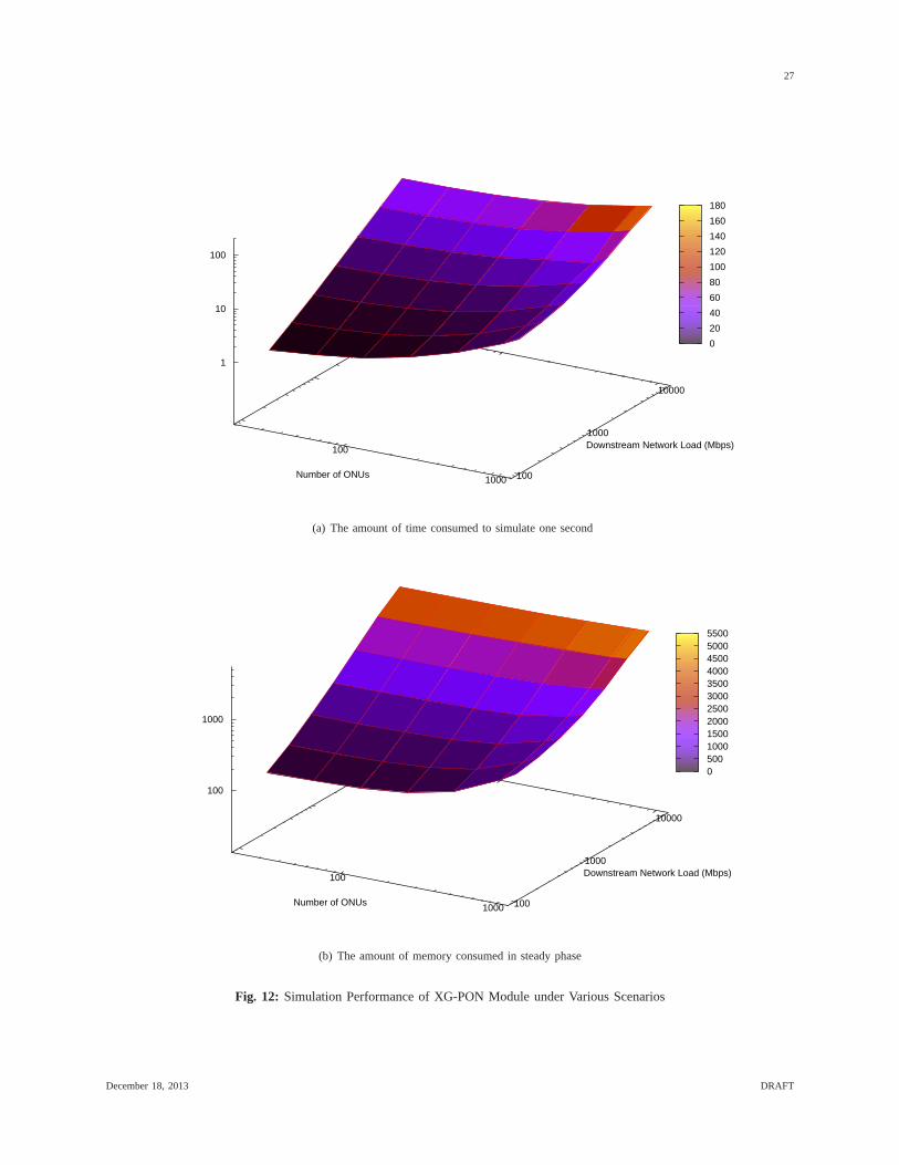
To evaluate the speed of our XG-PON module, 400 seconds are simulated in each experiments, the total amount
of time used to complete the simulation is recorded, and we then calculate and plot the amount of time consumed to
simulated one second. Figure 12(a) shows the results under various scenarios. It indicates that the consumed time is
increased linearly with the network load. It is reasonable since NS-3 is one packet-level network simulator and the
number of events are increased linearly with the number of packets. Figure 12(a) also indicates that the consumed
time increases with the number of ONUs much slower. Hence, our XG-PON module have successfully avoid to let
each ONU process all packets in the downstream direction. Figure 12(a) also indicates that our XG-PON module
takes around 160s to simulate one second even when there are 1000 ONUs and the downstream network load is
9.6Gbps with which XG-PON has been over-loaded.
We have also usedgdb to run the simulation of the most difficult scenario (ONUs: 1000; Network load: 9.6Gbps)
in debug mode. After the simulation enters into steady phase, we break it at random time, check the call stack,
and continue the simulation. These steps are repeated for 126 times and the CPU is running our XG-PON code for
only 4 times. Thus, our XG-PON module is not the bottleneck for simulation speed and other modules (routing,
etc.) need be revised for improving the speed further.
Not only simulation speed, we have also evaluated the amountof memory consumed by XG-PON simulation.
The same experiments are repeated to collect these results.For each experiments, after starting the simulation, we
wait for a long time until the simulation enters into its steady phase and the amount of consumed memory does not
increase anymore. These values for various scenarios are recorded and plotted in Figure 12(b). This plot indicates
that the consumed memory increases linearly with the network load, and it increase much slower with the number
of ONUs. When there are 1000 ONUs and the downstream network load is 9.6Gbps, the consumed memory is still
less than 5GBytes.
In summary, with off-the-shelf servers, our XG-PON module can simulate a 1000 ONUs 10Gbps XG-PON
network with reasonable speed and moderate memory consumption.
December 18, 2013 DRAFT
27
100
1000 100
1000
10000
1
10
100
Number of ONUs
Downstream Network Load (Mbps)
0
20
40
60
80
100
120
140
160
180
(a) The amount of time consumed to simulate one second
100
1000 100
1000
10000
100
1000
Number of ONUs
Downstream Network Load (Mbps)
0 500 1000 1500 2000 2500 3000 3500 4000 4500 5000 5500
(b) The amount of memory consumed in steady phase
Fig. 12: Simulation Performance of XG-PON Module under Various Scenarios
December 18, 2013 DRAFT

28
B. Pressure Tests
To evaluate the robustness of our XG-PON module, we have carried out more experiments. In one group of
experiments, we use the same configurations designed for performance evaluation and 4000 seconds are simulated
in each experiment to demonstrate that our XG-PON module cansimulate XG-PON for a long period (longer than
one hour). Note that when there are 1000 ONUs and the downstream network load is 9.6Gbps, it takes more than
one week to complete the simulation. All of these simulations have been carried out successfully, and there is no
crash and memory leakage in the course. In another group of experiments, we randomly select the number of ONUs
and the amount of network traffic, and 500 seconds are simulated in each experiment. For 49 random configurations
evaluated by us, all simulations have been carried out successfully.
In summary, evaluation results in this section indicate that our XG-PON module is quite robust and can simulate
XG-PON with reasonable speed and moderate memory consumption. It could be a good research platform for
studying performance issues related with XG-PON.
VII. SUMMARY AND FUTURE WORK
In this report, we introduce an XG-PON module for the NS-3 network simulator. We describe the details of its
design and implementation, and present some preliminary evaluation results. These results indicate that our XG-
PON module is quite robust and can simulate XG-PON with reasonable speed and moderate memory consumption.
As the first XG-PON module for NS-3, we believe that this work is a significant contribution to the scientific
community as it allows us to simulate XG-PON and study the performance issues that arise with the deployment
of XG-PON.
In the future, we will implement more scheduling and DBA algorithms that were proposed for G-PON or XG-
PON. We will also keep improving its simulation speed and parallel/distributed simulation will be considered.
Furthermore, we will study how to simulate Fiber to the Cell with this XG-PON module and the WiMAX/LTE
modules distributed with NS-3. The potential performance issues mentioned in this report will also be investigated
using this XG-PON module.
VIII. A CKNOWLEDGMENTS
This work is supported in part by Science Foundation of Ireland through CTVR (http://www.ctvr.ie/).
December 18, 2013 DRAFT

29
APPENDIX A
INSTALLATION
This appendix briefly introduces how to install our XG-PON module with NS-3. Here, we assume that NS-3 had
been installed on your computer and you are using the development code tree.
In this release of our XG-PON module, all files are put into onefolder ”xgpon”. In ”xgpon”, there are several
folders that are similar to other NS-3 modules, such as ”bindings” (for Ptyhon bindings), ”doc” (for documentations
included this manual), ”examples” (for examples to demonstrate how to use this module), ”helper” (for classes
provided to researcher with aim to facilitate its usage), ”model” (fore source code), and ”test” (for test cases).
In ”xgpon”, we have another folder ”changesOnOtherModules” that contains some bug fixes related with other
modules. Currently, we just changed ”ipv4-l3-protocol.cc” of the internet module to avoid program crash when long
simulations are carrying out.
To use this XG-PON module, you should copy or link ”xgpon” under the folder ”ns-3-dev/src”. You should
also copy our ”ipv4-l3-protocol.cc” into ”ns-3-dev/src/internet/model”. Considering that ”ipv4-l3-protocol.cc”might
evolve with NS-3, it’s better to search our copy with ”XG-PON” for identifying the changes, and change ”ipv4-l3-
protocol.cc” in the latest NS-3 release accordingly. Afterthat, please configure and build NS-3 as normal. XG-PON
module should be ready to be explored.
In addition, in ”xgpon”, there is one folder ”scripts4evaluation” that holds the scripts used by us to evaluate
this module. Before running these evaluations, you need copy the corresponding script file into ”ns-3-dev”. To
test GiantMAC through running ”pedro/pargiantscript.py”), you need set one new environment parameter (NS3)
according to the path of NS-3 on your system. You should also create ”data/giant-data” folder in your NS-3
installation.
December 18, 2013 DRAFT
30
APPENDIX B
SOURCEFILES
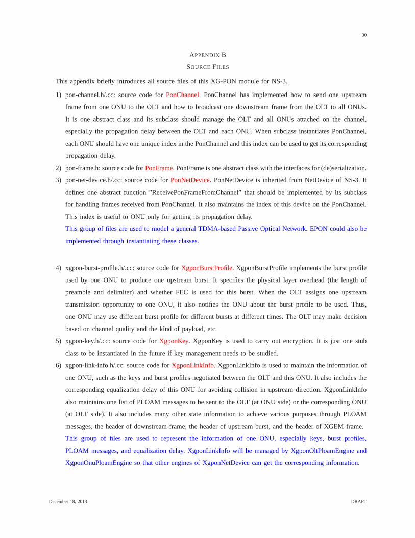
This appendix briefly introduces all source files of this XG-PON module for NS-3.
1) pon-channel.h/.cc: source code forPonChannel. PonChannel has implemented how to send one upstream
frame from one ONU to the OLT and how to broadcast one downstream frame from the OLT to all ONUs.
It is one abstract class and its subclass should manage the OLT and all ONUs attached on the channel,
especially the propagation delay between the OLT and each ONU. When subclass instantiates PonChannel,
each ONU should have one unique index in the PonChannel and this index can be used to get its corresponding
propagation delay.
2) pon-frame.h: source code forPonFrame. PonFrame is one abstract class with the interfaces for (de)serialization.
3) pon-net-device.h/.cc: source code forPonNetDevice. PonNetDevice is inherited from NetDevice of NS-3. It
defines one abstract function ”ReceivePonFrameFromChannel” that should be implemented by its subclass
for handling frames received from PonChannel. It also maintains the index of this device on the PonChannel.
This index is useful to ONU only for getting its propagation delay.
This group of files are used to model a general TDMA-based Passive Optical Network. EPON could also be
implemented through instantiating these classes.
4) xgpon-burst-profile.h/.cc: source code forXgponBurstProfile. XgponBurstProfile implements the burst profile
used by one ONU to produce one upstream burst. It specifies thephysical layer overhead (the length of
preamble and delimiter) and whether FEC is used for this burst. When the OLT assigns one upstream
transmission opportunity to one ONU, it also notifies the ONUabout the burst profile to be used. Thus,
one ONU may use different burst profile for different bursts at different times. The OLT may make decision
based on channel quality and the kind of payload, etc.
5) xgpon-key.h/.cc: source code forXgponKey. XgponKey is used to carry out encryption. It is just one stub
class to be instantiated in the future if key management needs to be studied.
6) xgpon-link-info.h/.cc: source code forXgponLinkInfo. XgponLinkInfo is used to maintain the information of
one ONU, such as the keys and burst profiles negotiated between the OLT and this ONU. It also includes the
corresponding equalization delay of this ONU for avoiding collision in upstream direction. XgponLinkInfo
also maintains one list of PLOAM messages to be sent to the OLT(at ONU side) or the corresponding ONU
(at OLT side). It also includes many other state informationto achieve various purposes through PLOAM
messages, the header of downstream frame, the header of upstream burst, and the header of XGEM frame.
This group of files are used to represent the information of one ONU, especially keys, burst profiles,
PLOAM messages, and equalization delay. XgponLinkInfo will be managed by XgponOltPloamEngine and
XgponOnuPloamEngine so that other engines of XgponNetDevice can get the corresponding information.
December 18, 2013 DRAFT

31
7) xgpon-xgtc-ploam.h/.cc: source code forXgponXgtcPloam.XgponXgtcPloam is used to represent one PLOAM
message exchanged between OLT and ONU. Since PLOAM messagesneed to be allocated and released
dynamically during simulation, the new and delete operators of XgponXgtcPloam are overridden and a pool
is maintained for reducing the cost of the expensive ”malloc” operations.
8) xgpon-xgem-header.h/.cc: source code forXgponXgemHeader. XgponXgemHeader is the header of XGEM
frame exchanged between OLT and ONU. It is one member variable of the following XgponXgemFrame.
9) xgpon-xgem-frame.h/.cc: source code forXgponXgemFrame. XgponXgemFrame is used to encapsulate SDU
from upper layers. Except one XgponXgemHeader and the potential SDU, it also has one member variable
used to specify the type of this XGEM frame (normal frame, idle frame, or short idle frame). Since huge
amount of XGEM frames need to be allocated and released dynamically, its new and delete operators are
also overridden and a pool is maintained for reducing the cost of the expensive ”malloc” operations.
10) xgpon-ds-frame.h/.cc: source code forXgponDsFrame. XgponDsFrame is one subclass of PonFrame for XG-
PON. It is designed to represent one downstream frame broadcasted from OLT to ONUs. It mainly contains
two member variables, one for physical layer header (XgponPsbd) and the other for XGTC layer downstream
frame (XgponXgtcDsFrame). For saving CPU used to allocate and release this structure, its new and delete
operators are also overridden and a pool is maintained for reducing the cost of the expensive ”malloc”
operations.
11) xgpon-psbd.h/.cc: source code forXgponPsbd. XgponPsbd is the physical layer header of the downstream
frame of XG-PON (XgponDsFrame).
12) xgpon-xgtc-ds-frame.h/.cc: source code forXgponXgtcDsFrame. XgponXgtcDsFrame is the downstream frame
observed by XGTC layer. It mainly includes one XGTC layer header (XgponXgtcDsHeader) and a bunch
of XGEM frames. To allow hundreds of ONUs to process one XgponXgtcDsFrame quickly, we separate the
broadcasted XGEM frames that must be processed by all ONUs and the uni-casted ones. Considering that
one XgponXgtcDsFrame may contain the traffic of just a few ONUs, most of ONUs need not parse these uni-
casted XGEM frames for extracting their own traffic. Thus, a bitmap is also added into XgponXgtcDsFrame
to indicate the ONUs whose traffic are within this frame.
13) xgpon-xgtc-ds-header.h/.cc: source code forXgponXgtcDsHeader. XgponXgtcDsHeader is the XGTC layer
header of a downstream frame (XgponXgtcDsFrame). It contains a list of PLOAM messages (XgponXgtc-
Ploam) to be sent to ONUs and the following XgponXgtcBwmap used to instruct ONUs how to share the
upstream wavelength.
14) xgpon-xgtc-bwmap.h/.cc: source code forXgponXgtcBwmap. XgponXgtcBwmap is produced by the OLT
and broadcasted to all ONUs in the header of the XGTC downstream frame (XgponXgtcDsHeader). It is used
to instruct ONUs how to share the upstream wavelength in a TDMA-like manner. It includes a list of the
following XgponXgtcBwAllocation. For saving CPU used to allocate and release this structure, its new and
delete operators are also overridden and a pool is maintained for reducing the cost of the expensive ”malloc”
December 18, 2013 DRAFT

32
operations.
15) xgpon-xgtc-bw-allocation.h/.cc: source code forXgponXgtcBwAllocation. In XgponXgtcBwmap, there is one
XgponXgtcBwAllocation for each T-CONT scheduled in the corresponding upstream frame. XgponXgtcB-
wAllocation is used to specify when one ONU should send the upstream traffic of this T-CONT, how many
bytes it can send, and whether it can send one queue occupancyreport. The XgponXgtcBwAllocation of
the same ONU will form one upstream burst. For the first XgponXgtcBwAllocation of the same burst, it
also specifies the burst profile used by the corresponding upstream burst and whether the ONU can send
one PLOAM message to the OLT. For saving CPU used to allocate and release this structure, its new and
delete operators are also overridden and a pool is maintained for reducing the cost of the expensive ”malloc”
operations.
16) xgpon-us-burst.h/.cc: source code forXgponUsBurst. XgponUsBurst is one subclass of PonFrame for XG-
PON. It is designed to represent one upstream burst that one ONU sends to the OLT in upstream direction. It
mainly contains two member variables, one for physical layer header (XgponPsbu) and the other for XGTC
layer upstream burst (XgponXgtcUsBurst). For saving CPU used to allocate and release this structure, its
new and delete operators are also overridden and a pool is maintained for reducing the cost of the expensive
”malloc” operations.
17) xgpon-psbu.h/.cc: source code forXgponPsbu. XgponPsbu is the physical layer header of the upstream burst
of XG-PON (XgponUsBurst). It contains the preamble and delimiter. Their length is determined by the burst
profile used for this burst. And the burst profile is selected by the OLT and specified in the corresponding
XgponXgtcBwmap.
18) xgpon-xgtc-us-burst.h/.cc: source code forXgponXgtcUsBurst. XgponXgtcUsBurst is the upstream burst
observed by XGTC layer. It mainly includes one XGTC layer header (XgponXgtcUsHeader), a trailer, and a
bunch of the following XgponXgtcUsAllocation (one for eachT-CONT).
19) xgpon-xgtc-us-header.h/.cc: source code forXgponXgtcUsHeader. XgponXgtcUsHeader is the XGTC layer
header of an upstream burst (XgponXgtcUsBurst). If scheduled by the OLT, one PLOAM message can also
be sent to the OLT within this header.
20) xgpon-xgtc-us-allocation.h/.cc: source code forXgponXgtcUsAllocation. XgponXgtcUsAllocation is designed
to represent the traffic of one T-CONT to be transmitted in theupstream burst. It mainly contains a bunch
of XGEM frames. If scheduled by the OLT through XgponXgtcBwmap, one queue occupancy report (Xg-
ponXgtcDbru) is also transmitted in XgponXgtcUsAllocation. For saving CPU used to allocate and release
this structure, its new and delete operators are also overridden and a pool is maintained for reducing the cost
of the expensive ”malloc” operations.
21) xgpon-xgtc-dbru.h/.cc: source code forXgponXgtcDbru. XgponXgtcDbru is used to represent one queue
occupancy report of one T-CONT.
This group of files are used to represent the information communicated between the OLT and ONU. For
December 18, 2013 DRAFT
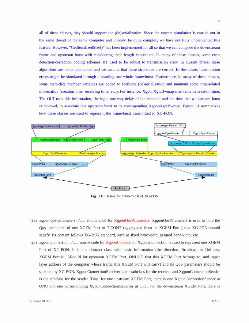
33
all of these classes, they should support the (de)serialization. Since the current simulation is carried out in
the same thread of the same computer and it could be quite complex, we have not fully implemented this
feature. However, ”GetSerializedSize()” has been implemented for all so that we can compose the downstream
frame and upstream burst with considering their length constraints. In many of these classes, some error
detection/correction coding schemes are used to be robust to transmission error. In current phase, these
algorithms are not implemented and we assume that these structures are correct. In the future, transmission
errors might be simulated through discarding one whole frame/burst. Furthermore, in many of these classes,
some meta-data member variables are added to facilitate (de)serialization and maintain some time-related
information (creation time, receiving time, etc.). For instance, XgponXgtcBwmap maintains its creation time.
The OLT uses this information, the logic one-way-delay of the channel, and the time that a upstream burst
is received, to associate this upstream burst to its corresponding XgponXgtcBwmap. Figure 13 summarizes
how these classes are used to represent the frame/burst transmitted in XG-PON.
Fig. 13: Classes for frame/burst of XG-PON
22) xgpon-qos-parameters.h/.cc: source code forXgponQosParameters. XgponQosParameters is used to hold the
Qos parameters of one XGEM Port or T-CONT (aggregated from its XGEM Ports) that XG-PON should
satisfy. Its content follows XG-PON standard, such as fixed bandwidth, assured bandwidth, etc.
23) xgpon-connection.h/.cc: source code forXgponConnection. XgponConnection is used to represent one XGEM
Port of XG-PON. It is one abstract class with basic information (the direction, Broadcast or Uni-cast,
XGEM Port-Id, Alloc-Id for upstream XGEM Port, ONU-ID that this XGEM Port belongs to, and upper
layer address of the computer whose traffic this XGEM Port will carry) and its QoS parameters should be
satisfied by XG-PON. XgponConnectionReceiver is the subclass for the receiver and XgponConnectionSender
is the subclass for the sender. Thus, for one upstream XGEM Port, there is one XgponConnectionSender at
ONU and one corresponding XgponConnectionReceiver at OLT.For the downstream XGEM Port, there is
December 18, 2013 DRAFT

34
one XgponConnectionSender at OLT and one corresponding XgponConnectionReceiver at ONU. The QoS
parameters at the sender and the receiver must be identical.
24) xgpon-connection-receiver.h/.cc: source code forXgponConnectionReceiver. As the subclass of XgponCon-
nection for the receiver, XgponConnectionReceiver is quite simple. It mainly holds the segments that have
been received to carry out reassemble in the future. Note that, for upstream traffic, reassemble is carried out
by the OLT per T-CONT.
25) xgpon-connection-sender.h/.cc: source code forXgponConnectionSender. XgponConnectionSender is the XGEM
Port instance at the sender. It has one queue (XgponQueue) tobuffer the traffic to be transmitted on XG-
PON and a list of service records (XgponServiceRecord) thatcould be used for scheduling purposes. It is
also responsible to receive the SDU (put it into the queue), get the packet to be transmitted on XG-PON
(fragmentation needs to be considered), maintain its serving history (a list of XgponServiceRecord), and return
the occupancy of its queue.
26) xgpon-service-record.h/.cc: source code forXgponServiceRecord. XgponServiceRecord is used to store the
event that one XGEM Port is served. It records the time that the traffic of this XGEM Port are transmitted
and the amount of bytes transmitted through XG-PON. For saving CPU used to allocate and release this
structure, its new and delete operators are also overriddenand a pool is maintained for reducing the cost of
the expensive ”malloc” operations.
27) xgpon-queue.h/.cc: source code forXgponQueue. XgponQueue is used for each XGEM Port at the sender. It
is used to hold the traffic to be transmitted through XG-PON. Instead of Queue from NS-3, XgponQueue is
added for three reasons. First, fragmentation need to be considered and it should hold the remaining part of
one fragmented SDU and send the remaining part immediately once this XGEM Port is served again. Second,
some variables in ns3::Queue are private and we cannot update them. Third, when SDU is encapsulated into
XGEM frame, padding must be carried out for word-alignment.Thus, queue occupancy must be updated
accordingly. Instead of calculating queue occupancy (visiting each packet in the queue) when needed, this
value is maintained when packet is enqueued/dequeued, two calculations are necessary for each packet, and
CPU can be saved. Note that XgponQueue is one abstract class and its subclass is responsible to manage
packets in the queue and implement some queue discipline.
28) xgpon-fifo-queue.h/.cc: source code forXgponFifoQueue. XgponFifoQueue is one subclass of XgponQueue
and it follows the principles of FIFO (First In, First Out).
29) xgpon-tcont.h/.cc: source code forXgponTcont. XgponTcont is used to represent one T-CONT (Note that
one T-CONT might have multiple upstream XGEM Ports) of XG-PON. It is one abstract class with basic
information (Alloc-Id, ONU-ID that this T-CONT belongs to). XgponTcontOlt is the subclass used by the
OLT and XgponTcontOnu is the subclass used by ONU. In addition, XgponTcont also holds a list of
XgponXgtcDbru (the history of queue occupancy reports) anda list of XgponXgtcBwAllocation (the serving
history) related with this T-CONT. These information couldbe used by the OLT to deduce how many data
December 18, 2013 DRAFT
35
of this T-CONT is still waiting at ONU to be served.
30) xgpon-tcont-olt.h/.cc: source code forXgponTcontOlt. XgponTcontOlt is the T-CONT instance at the OLT.
It has a list of XgponConnectionReceiver that are used to calculate its aggregated QoS parameters. It is
responsible to carry out reassemble, receive queue occupancy report from ONU, maintain its serving history
and queue occupancy reports, and calculate the amount of data at ONU that still needs to be served. When
there is no queue occupancy reports from ONU, it is also responsible to tell the OLT whether to poll the
ONU for the status of this T-CONT.
31) xgpon-tcont-onu.h/.cc: source code forXgponTcontOnu. XgponTcontOnu is the T-CONT instance at ONU. It
has a list of XgponConnectionSender that belong to this T-CONT. It is responsible to maintain these connec-
tions, generate queue occupancy report, and maintain the serving history (a list of XgponXgtcBwAllocation
from the OLT). Since the OLT just assigns the upstream bandwidth to T-CONTs, XgponTcontOnu has one
upstream scheduler (XgponOnuUsScheduler) used to schedule traffic of the connections that belong to the
same T-CONT. Through putting one upstream scheduler into XgponTcontOnu, we can use different upstream
schedulers for different T-CONTs.
32) xgpon-onu-us-scheduler.h/.cc: source code forXgponOnuUsScheduler. XgponOnuUsScheduler is used to
schedule traffic of the connections that belong to the same T-CONT. When one upstream burst need to
be produced, XgponOnuUsScheduler is used by ONU to determine the traffic to be put into this burst. The
main interface is ”SelectConnToServe”, a virtual functionthat its subclass must be implement to determine
the connection to be served and the amount of data to be transmitted.
33) xgpon-onu-us-scheduler-round-robin.h/.cc: source code for XgponOnuUsSchedulerRoundRobin. XgponOnu-
UsSchedulerRoundRobin is one subclass of XgponOnuUsScheduler that schedules the upstream connections
of the same T-CONT in round-robin manner with considering their queue occupancy.
This group of files are used to represent XGEM Port and T-CONT in XG-PON. At the sender, there is one
queue for each XGEM Port. Fragmentation and reassemble are considered in these classes. Qos parameters
and serving history are also maintained in these classes.
34) xgpon-channel.h/.cc: source code forXgponChannel. XgponChannel is a subclass of PonChannel for XG-
PON. It maintains the logic one-way-delay for the whole XG-PON network, which should be set based on
the largest propagation delay among all ONUs and various processing delays. In XG-PON, all nodes (OLT
and ONUs) have a consistent view of this value. Correspondingly, each ONU has one equalization delay that
is related with the logic one-way-delay and its own propagation delay (between this ONU and the OLT).
35) xgpon-phy.h/.cc: source code ofXgponPhy. XgponPhy contains the physical layer parameters of one XG-PON
network and provides several common routines. These parameters can be configured through NS-3 attribute
system. Through changing these parameters, we could simulate GPON approximately.
36) xgpon-net-device.h/.cc: source code forXgponNetDevice. XgponNetDevice is a subclass of PonNetDevice that
December 18, 2013 DRAFT

36
implements the common functions for both OLT and ONU. It implements ”Send” and ”SendFrom” inherited
from NetDevice for accepting packets from upper layers. However, these functions just trace these events and
the main jobs are done by ”DoSend” and ”DoSendFrom” that willbe instantiated by XgponOnuNetDevice
and XgponOltNetDevice. XgponNetDevice also provides functions to other components for sending SDU
to upper layers and supporting Pcap and Ascii tracing. It also maintains a per-device statistics, such as the
amount of data received from upper layer, dropped due to buffer overflow, etc. It also has one instance of
XgponPhy so that the engines of XgponOltNetDevice/XgponOnuNetDevice can get to know physical layer
parameters used in simulation.
37) xgpon-olt-net-device.h/.cc: source code forXgponOltNetDevice. XgponOltNetDevice is a subclass of Xg-
ponNetDevice for the OLT. It has a bunch of engines that implement various functions of the XGTC layer
for the OLT. These engines will be introduced below. XgponOltNetDevice has implemented ”ReceivePon-
FrameFromChannel” for processing the upstream bursts fromONUs with its engines. It also has implemented
”DoSend” and ”DoSendFrom” to put the packets from the upper layers to their corresponding queues. When
this class is initiated at the beginning of the simulation, ”SendDownstreamFrameToChannelPeriodically” is
called to periodically (125 micro-second) generate a downstream frame with its engines and pass the frame
to XgponChannel for broadcasting to all ONUs.
38) xgpon-onu-net-device.h/.cc: source code forXgponOnuNetDevice. XgponOnuNetDevice is a subclass of
XgponNetDevice for ONU. It has a bunch of engines that implement various functions of the XGTC layer
for ONU. XgponOnuNetDevice has implemented ”ReceivePonFrameFromChannel” for processing the down-
stream frames from the OLT with its engines. It also has implemented ”DoSend” and ”DoSendFrom” to put
the packets from the upper layers to their corresponding queues. XgponOnuNetDevice also provides ”Produce-
AndTransmitUsBurst” in which one upstream burst is produced with its engines and pass to XgponChannel
for sending to the OLT. This function is used when ONU processes XgponXgtcBwmap and schedules to
produce the burst assigned by the OLT.
This group of files are used to implement XG-PON through instantiating PonNetDevice and PonChannel.
Within XgponOltNetDevice, their engines need to call each other’s functions quite frequently. Although we
can decouple these engines through adding functions into XgponOltNetDevice (these functions will simply
delegate the tasks to the corresponding engines), these engines are tightly coupled and too many functions
need to be added. Thus, we let each engine have one reference of XgponOltNetDevice and the engine can
access other engines through XgponOltNetDevice. For XgponOnuNetDevice, the situation is similar and we
handle in the same way.
39) xgpon-olt-engine.h/.cc: source code forXgponOltEngine. XgponOltEngine is the base class of the following
engines used by XgponOltNetDevice. Through inheriting from XgponOltEngine, each engine will have one
reference of XgponOltNetDevice, which can be used to accessother related engines.
December 18, 2013 DRAFT

37
40) xgpon-onu-engine.h/.cc: source code forXgponOnuEngine. XgponOnuEngine is the base class of the following
engines used by XgponOnuNetDevice. Through inheriting from XgponOnuEngine, each engine will have one
reference of XgponOnuNetDevice, which can be used to accessother related engines.
41) xgpon-olt-conn-per-onu.h/.cc: source code forXgponOltConnPerOnu. At the OLT, XgponOltConnPerOnu is
used to hold the downstream XGEM Ports and the T-CONTs that belong to one ONU.
42) xgpon-olt-conn-manager.h/.cc: source code forXgponOltConnManager. XgponOltConnManager is designed
to maintain all XGEM Ports and T-CONTs at the OLT. For each XGEM Port or T-CONT, it could be put into
several data structures for different purposes. In fact, There is only one instance of XGEM Port or T-CONT.
We just put one smart pointer that points to this XGEM Port or T-CONT to these data structures. Thus,
the memory overhead won’t be increased significantly. Thereis one vector of XgponOltConnPerOnu and
the index of one ONU’s XgponOltConnPerOnu equals to its ONU-ID. The broadcast downstream XGEM
Ports are organized separately. The main function of XgponOltConnManager is to find the corresponding
XGEM Port when receiving one packet from the upper layer and to find the corresponding T-CONT when
one upstream burst is received from XgponChannel. For processing the upstream burst quickly, all T-CONTs
(XgponTcontOlt) are organized into one vector and the indexof one XgponTcontOlt equals to its Alloc-Id.
For the downstream XGEM Ports (XgponConnectionSender), they are organized differently in the following
two subclasses of XgponOltConnManager.
43) xgpon-olt-conn-manager-speed.h/.cc: source code forXgponOltConnManagerSpeed. XgponOltConnManager-
Speed is one subclass of XgponOltConnManager designed to quickly map the packet from upper layer to
its corresponding XGEM Port (XgponConnectionSender). Alldownstream XGEM Ports (XgponConnection-
Sender) are organized into one vector and the index of one XgponConnectionSender is its XGEM Port-Id.
There is one pre-defined relationship between the XGEM Port-Id, the upper layer address of the computer
that this XGEM Port is configured for, and the ONU-ID of the ONUthat this computer is attached to.
When the OLT gets one packet from the upper layer, based on the destination address in packet header, the
corresponding XGEM Port-Id can be calculated directly and the corresponding XgponConnectionSender can
be found very quickly (O(1)). There are several shortcomings in this solution. First, XGEM Port-Id is 16-bit
and the vector may waste a lot of memory when there are a few XGEM Ports in the system. Considering
that there are only one OLT, the memory overhead should be acceptable. Second, due to the relationship
among XGEM Port-Id, Address, and ONU-ID, there will be some constraints on the number of XGEM Ports
per ONU. In the current implementation, the maximal XGEM Ports of one ONU is 64. It should be enough
unless we simulate some special cases.
44) xgpon-olt-conn-manager-flexible.h/.cc: source code for XgponOltConnManagerFlexible. XgponOltConnMan-
agerFlexible is one subclass of XgponOltConnManager designed for flexibility, i.e., one ONU could have
a large number of XGEM Ports. In this class, all downstream XGEM ports (XgponConnectionSender) are
organized into one map and the key is the upper layer address of the computer that this XGEM Port is
December 18, 2013 DRAFT

38
configured for. Thus, it takesO(log(n)) to map one packet from upper layer to the corresponding Xgpon-
ConnectionSender.
45) xgpon-onu-conn-manager.h/.cc: source code forXgponOnuConnManager. XgponOnuConnManager is de-
signed to maintain the XGEM Ports and T-CONTs that belongs toone ONU. It also maintains Xgpon-
ConnectionReceiver for the broadcast downstream XGEM Portfor receiving the broadcasted traffic. For each
XGEM Port or T-CONT, it could be put into several data structures for different purposes. In fact, There
is only one instance of XGEM Port or T-CONT. We just put one smart pointer that points to this XGEM
Port or T-CONT to these data structures. Thus, the memory overhead won’t be increased significantly. The
main functions of XgponOnuConnManager are to find the corresponding downstream XGEM Port (Xgpon-
ConnectionReceiver) when receiving one XGEM frame from XgponChannel and to find the corresponding
upstream XGEM Port (XgponConnectionSender) when receiving one packet from upper layer. Its T-CONTs
(XgponTcontOnu) should also be maintained for T-CONT related operations. The following two subclasses
of XgponOnuConnManager are designed for speed and flexibility, respectively.
46) xgpon-onu-conn-manager-speed.h/.cc: source code forXgponOnuConnManagerSpeed. For each ONU, it needs
to check millions of XGEM frames per second to filter out the traffic for itself. Considering that there
could be hundreds of ONUs in XG-PON, the operation of mappingXGEM frame to the corresponding
XgponConnectionReceiver must be carried out very quickly.One naive solution is to add one vector for each
ONU and let the index of XgponConnectionReceiver equal to its XGEM Port-Id. However, the vectors in
all ONUs may consume too much memory. Thus, we use one pre-defined relationship between the XGEM
Port-Id, the upper layer address of the computer that this XGEM Port is configured for, and the ONU-
ID of the ONU that this computer is attached to. Based on XGEM Port-Id and ONU-ID, we can judge
whether this XGEM Port belongs to this ONU. When it does belongto this ONU, we can produce a small
number based on XGEM Port-Id and ONU-ID, and this number is used as the index of the corresponding
XgponConnectionReceiver in a much smaller vector. The upstream XGEM Ports (XgponConnectionSender)
and T-CONTs (XgponTcontOnu) are treated similarly. When receiving one packet from upper layer, we
calculate the index of the corresponding XGEM Port (XgponConnectionSender) based on the source address
in packet header. Similarly, due to the relationship among XGEM Port-Id, Address, and ONU-ID, there are
some constraints on the number of XGEM Ports and T-CONTs configured for one ONU.
47) xgpon-onu-conn-manager-flexible.h/.cc: source code for XgponOnuConnManagerFlexible. XgponOnuConn-
ManagerFlexible is one subclass of XgponOnuConnManager designed for flexibility, i.e., one ONU could
have a large number of XGEM Ports and T-CONTs. In this class, all downstream/upstream XGEM Ports and
T-CONTs are organized into one vector or one map. Thus, it takesO(log(n)) or O(n) when searching the
corresponding data structures (XgponConnectionSender, XgponConnectionReceiver, XgponTcontOnu, etc.).
This group of files are used to manage XGEM Port and T-CONT at OLT and ONU. They are designed
carefully so that the corresponding XGEM Port can be found quickly when one SDU is received from upper
December 18, 2013 DRAFT

39
layer or one XGEM frame is received from XgponChannel. In XG-PON standard, the SDU could be IP
packets or layer-2 frames of various network technologies (Ethernet, ATM, etc.). In current implementation,
we assume that the SDU is IP packet and the IP address of the computer attached to ONU is used for
mapping. Furthermore, we can only configure one XGEM Port foreach computer since only IP address
is considered. Thus, to simulating multiple XGEM Ports per ONU, we need connect multiple nodes to
this ONU. For XgponOltConnManagerSpeed and XgponOnuConnManagerSpeed, there are some pre-defined
relationship among XGEM Port-Id, IP address, and ONU-ID. The same relationship should also be applied
when allocating XGEM Port-Id and Alloc-ID to one ONU. This correlation is ensured through XgponHelper
that will be introduced below.
48) xgpon-olt-dba-per-burst-info.h/.cc: source code forXgponOltDbaPerBurstInfo. In XG-PON, multiple T-CONTs
of the same ONU may be served in the same XgponXgtcBwmap and their corresponding XgponXgtcBwAllo-
cation should be put together to save the overhead of the upstream burst (Inter-burst gap, physical layer header,
etc.). XgponOltDbaPerBurstInfo is designed here to maintain these XgponXgtcBwAllocation that belong to
the same upstream burst.
49) xgpon-olt-dba-bursts.h/.cc: source code forXgponOltDbaBursts. In one upstream frame, multiple ONUs may
be served and one XgponXgtcBwmap needs to specify multiple bursts. Thus, XgponOltDbaBursts is designed
to maintain a list of bursts (XgponOltDbaPerBurstInfo) to be specified in one XgponXgtcBwmap. Note that
when producing XgponXgtcBwmap from XgponOltDbaBursts, the burst that is changed lastly must be the
last burst in XgponXgtcBwmap. Otherwise, if the size of the last changed burst is increased a lot, some short
bursts at the end of the list may be totally out of the boundarythe corresponding upstream frame and the
OLT cannot process these bursts correctly.
50) xgpon-olt-dba-engine.h/.cc: source code forXgponOltDbaEngine. XgponOltDbaEngine is one engine of Xg-
ponOltNetDevice. It is responsible to process queue occupancy report from ONU, i.e., pass the report to the
corresponding XgponTcontOlt. It also maintains a list of XgponXgtcBwmap that have been transmitted,
but the corresponding upstream bursts have not been received. When receiving one upstream burst, the
burst’s receiving time, these XgponXgtcBwmap and their creation time, and the logic one-way-delay of
XgponChannel will be used to find the XgponXgtcBwmap in whichthe burst was scheduled. The OLT
can then get to know the burst profile used by this burst and process this burst further. The last and
the most important task of XgponOltDbaEngine is to produce XgponXgtcBwmap for each downstream
frame. XgponXgtcBwmap notifies ONUs about how to share the upstream wavelength. When producing
XgponXgtcBwmap, XgponOltDbaBursts and XgponOltDbaPrBurstInfo are utilized. As for T-CONTs to be
served and the amount of allocated bandwidth, we let the subclass of XgponOltDbaEngine make these
decisions based on the DBA algorithm implemented by the subclass.
51) xgpon-olt-dba-engine-giant.h/.cc: source code forXgponOltDbaEngineGiant. XgponOltDbaEngineGiant is one
December 18, 2013 DRAFT
40
subclass of XgponOltDbaEngine and implements GiantMAC [22] proposed for GPON. It supports different
types of T-CONTs specified in GPON (Fixed, Assured, Non-Assured, and Best-effort) and the correponding
parameters can be configured through our helper class.
52) xgpon-olt-dba-parameters-giant.h/.cc: source code for the QoS parameters used by T-CONTs supported by
GiantMAC [22].
53) xgpon-olt-dba-engine-round-robin.h/.cc: source code forXgponOltDbaEngineRoundRobin. XgponOltDbaEngineR-
oundRobin is one subclass of XgponOltDbaEngine. It treats all T-CONTs equally and allocates upstream
bandwidth in a round-robin manner with considering queue occupancy reports from ONUs.
54) xgpon-onu-dba-engine.h/.cc: source code forXgponOnuDbaEngine. XgponOnuDbaEngine is one engine of
XgponOnuNetDevice. It implements DBA related functions atONU side. More specifically, it produces
queue occupancy report of one T-CONT when asked by the OLT. Italso processes XgponXgtcBwmap in
each downstream frame. In case that one or more T-CONTs of this ONU appear in XgponXgtcBwmap, it
will schedule one event to produce and transmit the upstreamburst at the corresponding time.
This group of files are used to implement DBA related functions at OLT and ONU. Considering that DBA is
a hot research topic, more subclasses of XgponOltDbaEnginewill be developed to implement various DBA
algorithms proposed for GPON or XG-PON.
55) xgpon-olt-ds-scheduler.h/.cc: source code forXgponOltDsScheduler. When producing the payload of each
downstream frame, the OLT needs to determine the downstreamXGEM Ports to be served. Thus, Xg-
ponOltDsScheduler is designed as one engine of XgponOltNetDevice. The main interface is ”SelectCon-
nToServe”, a virtual function that its subclass must implement to determine the XGEM Port to be served and
the amount of data to be transmitted in the downstream frame.
56) xgpon-olt-ds-scheduler-round-robin.h/.cc: source code forXgponOltDsSchedulerRoundRobin. XgponOltDsS-
chedulerRoundRobin is one subclass of XgponOltDsScheduler that schedules all downstream XGEM Ports
in round-robin manner with considering their queue occupancy.
This group of files are used to schedule the downstream traffic. In the future, more subclasses of XgponOltDsS-
cheduler will be developed to support different QoS parameters of the downstream XGEM Ports.
57) xgpon-xgem-routines.h/.cc: source code forXgponXgemRoutines. XgponXgemRoutines provides several rou-
tines used to generate one XgponXgemFrame. It is used by bothXgponOltXgemEngine and XgponOnuXge-
mEngine.
58) xgpon-olt-xgem-engine.h/.cc: source code forXgponOltXgemEngine. XgponOltXgemEngine is one engine
of XgponOltNetDevice. It is responsible to produce the payload of a downstream frame, a bunch of XGEM
frames. It calls XgponOltDsScheduler to determines the traffic to be transmitted in this downstream frame.
Fragmentation may be carried out in the course. XgponOltXgemEngine is also responsible to process XGEM
December 18, 2013 DRAFT

41
frames from ONU (Reassemble is carried out if needed). XgponOltXgemEngine is resorted once for the
payload of each T-CONT (XgponXgtcUsAllocation).
59) xgpon-onu-xgem-engine.h/.cc: source code forXgponOnuXgemEngine. XgponOnuXgemEngine is one engine
of XgponOnuNetDevice. It is responsible to produce the payload of one upstream burst. It is also resorted by
XgponOnuFramingEngine once for each T-CONT within this burst and it resorts to XgponOnuUsScheduler
of the T-CONT (XgponOnuTcont) for deciding the traffic to be transmitted. Fragmentation may be carried
out in the course. XgponOltXgemEngine is also responsible to process the XGEM frames from the OLT.
For each downstream frame, it will filter out XGEM frames for this ONU and carry out further processing
(reassemble, etc.).
60) xgpon-olt-framing-engine.h/.cc: source code forXgponOltFramingEngine. XgponOltFramingEngine is one
engine of XgponOltNetDevice and it is the core of the XGTC layer. Its main functions are to produce
XgponXgtcDsFrame to be transmitted in downstream direction and to process XgponXgtcUsBurst received
from ONU. When producing XgponXgtcDsFrame, it resorts otherengines to compose different parts of
XgponXgtcDsFrame. For instance, XgponOltDbaEngine is used to produce XgponXgtcBwmap and Xg-
ponOltXgemEngine is called to generate the payload, a bunchof XGEM frames. Similarly, other engines
are resorted to process different parts of one XgponXgtcUsBurst received from ONU.
61) xgpon-onu-framing-engine.h/.cc: source code forXgponOnuFramingEngine. XgponOnuFramingEngine is one
engine of XgponOnuNetDevice. It also plays the core role at ONU side. When producing XgponXgtcUsBurst,
XgponOnuDbaEngine is used to produce queue occupancy report and XgponOnuXgemEngine is called to
generate the payload, a bunch of XGEM frames. When processingXgponXgtcDsFrame, XgponOnuDbaEngine
is used to process XgponXgtcBwmap and XgponOnuXgemEngine is called to filter out and process XGEM
frames for this ONU.
62) xgpon-olt-phy-adapter.h/.cc: source code forXgponOltPhyAdapter. XgponOltPhyAdapter is one engine of
XgponOltNetDevice. It is responsible to implement the physic adaptation sub-layer of XG-PON standard at
OLT side. Currently, it is a stub class. In the future, transmission error may be simulated in this class.
63) xgpon-onu-phy-adapter.h/.cc: source code forXgponOnuPhyAdapter. XgponOnuPhyAdapter is one engine of
XgponOnuNetDevice. It is responsible to implement the physic adaptation sub-layer of XG-PON standard at
ONU side. Currently, it is a stub class. In the future, transmission error may be simulated in this class.
This group of files are used to implement the three sub-layersof XGTC layer. The framing sublayer plays
the core role and the information flow among these sublayers is illustrated in Figure 14.
64) xgpon-olt-ploam-engine.h/.cc: source code forXgponOltPloamEngine. XgponOltPloamEngine is one engine
of XgponOltNetDevice. It has a vector of XgponLinkInfo and the index of one XgponLinkInfo equals to the
corresponding ONU-ID.
December 18, 2013 DRAFT

42
Fig. 14: XG-PON Information Flow
65) xgpon-onu-ploam-engine.h/.cc: source code forXgponOnuPloamEngine. XgponOnuPloamEngine is one en-
gine of XgponOnuNetDevice. It has one XgponLinkInfo for itself.
Since our simulation module is designed to study performance issues of one running XG-PON, PLOAM
messages and the corresponding procedures (activation, ranging, etc.) are not simulated. The two classes are
used mainly for holding per-ONU information organized within XgponLinkInfo. In the future, these classes
may be enriched to simulate some PLOAM messages needed by theresearch.
66) xgpon-olt-omci-engine.h/.cc: source code forXgponOltOmciEngine. XgponOltOmciEngine is one engine of
XgponOltNetDevice.
67) xgpon-onu-omci-engine.h/.cc: source code forXgponOnuOmciEngine. XgponOnuOmciEngine is one engine
of XgponOltNetDevice.
Both the two classes are stub classes. OMCI for XG-PON is verycomplex and it takes too much time to
implement. For functions accomplished through OMCI channel (XGEM Port and T-CONT configuration,
etc.), we implement through XgponHelper.
December 18, 2013 DRAFT

43
68) xgpon-id-allocator.h/.cc: source code forXgponIdAllocator. When adding XGEM Port/T-CONT/ONU into
XG-PON, XgponIdAllocator is used to get one available XGEM Port-Id/Alloc-Id/ONU-ID. There are two
subclasses designed for allocating these IDs in different ways for different purposes.
69) xgpon-id-allocator-speed.h/.cc: source code forXgponIdAllocatorSpeed. As introduced above, to speed up
XG-PON simulation, we can impose some relationship among XGEM Port-Id, Alloc-Id, ONU-ID, and IP
address of the node connected to ONU. XgponIdAllocatorSpeed is the subclass designed to impose this
relationship.
70) xgpon-id-allocator-flexible.h/.cc: source code forXgponIdAllocatorFlexible. XgponIdAllocatorFlexible is the
subclass of XgponIdAllocator. It does not impose any relationship on XGEM Port-Id, Alloc-Id, ONU-ID, and
IP address of the node connected to ONU.
71) xgpon-config-db.h/.cc: source code forXgponConfigDb. XgponConfigDb is one database that holds the infor-
mation used by XgponHelper to configure XG-PON. For instance, it can be used by the researcher to change
the subclasses of XgponOltDbaEngine and XgponOltDsScheduler used in the simulation. It also uses one flag
to make sure that XgponOltConnManagerSpeed, XgponOnuConnManagerSpeed, and XgponIdAllocatorSpeed
are used together.
72) xgpon-helper.h/.cc: source code forXgponHelper. XgponHelper provides the main interfaces needed by
researchers for simulating XG-PON. ”Install()” is provided to install XgponOltNetDevice on the OLT and
install XgponOnuNetDevice on all ONUs. In this function, XgponOltNetDevice, XgponOnuNetDevice, and
their engines are created and configured. Thus, before calling ”Install()”, XgponConfigDb should be used to
specify the subclasses used in the simulation and the corresponding object factories must be initialized. The
attributes of some classes (XgponPhy, XgponChannel, etc.)can also be changed before calling ”Install()”.
Through XgponHelper, researcher can also enable Ascii or Pcap tracing. In XgponHelper, functions are also
provided to create XGEM Port and T-CONT for the network. Before calling these functions, XgponHelper
can be used to change QoS parameters and queue used by XGEM Port.
This group of files provide the interfaces used by researchers for simulating XG-PON. Firstly, the researcher
need specify the parameters through XgponConfigDb and XgponHelper. Secondly, the nodes for the OLT
and ONUs must be prepared and ”Install()” of XgponHelper is called to install XponOltNetDevice and
XgponOnuNetDevice on these nodes. Thirdly, after getting the corresponding IP address of the computers
connected to ONUs, XGEM Port and T-CONT can be configured through XgponHelper. Before creating
XGEM Port or T-CONT, their QoS parameters and queue can also be changed through XgponHelper.
December 18, 2013 DRAFT

44
APPENDIX C
XG-PON SIMULATION EXAMPLE
This appendix presents one example for XG-PON simulation with aim to demonstrate the usage of XgponHelper.
In this example, dumb-bell topology is adopted and bi-directional UDP traffics are generated between computers
in core network (Left Servers and Left Clients) and computers that access the Internet through XG-PON. The code
related with XG-PON simulation has been explained by comments started with ”////”. The most important steps are
to install XgponNetDevice on the OLT and ONUs, configure IP addresses for these nodes, and add XGEM Port
(and the T-CONT related with upstream XGEM Port) for carrying traffics of ONUs.
/∗∗∗∗∗∗∗∗∗∗∗∗∗∗∗∗∗∗∗∗∗∗∗∗∗∗∗∗∗∗∗∗∗∗∗∗∗∗∗∗∗∗∗∗∗∗∗∗∗∗∗∗∗∗∗∗∗∗∗∗∗∗
∗ Th is s c r i p t w i l l c r e a t e UDP c l i e n t and s e r v e r a t bo th s i d e s t og e n e r a t e two−way t r a f f i c s .
∗
∗ P2P
∗ −−−−−−− ONU1−−−−−−−−−− UDP s i n k / sende r 1
∗ P2P P2P (CN) /
∗ L e f t S e r v e r s−−−−−−−−−−−−−− Gateway−−−−−−−−−−−− OLT−−−−−
∗ | \ P2P
∗ P2P | −−−−−− ONUn−−−−−−−−−− UDP s i n k / sende r n
∗ L e f t C l i e n t s−−−−−−−−−−−−−−−−−
∗∗∗∗∗∗∗∗∗∗∗∗∗∗∗∗∗∗∗∗∗∗∗∗∗∗∗∗∗∗∗∗∗∗∗∗∗∗∗∗∗∗∗∗∗∗∗∗∗∗∗∗∗∗∗∗∗∗∗∗∗∗ /
# i n c l u d e <i o s t r eam>
# i n c l u d e <f s t ream>
# i n c l u d e ” ns3 / core−module . h ”
# i n c l u d e ” ns3 / network−module . h ”
# i n c l u d e ” ns3 / i n t e r n e t−module . h ”
# i n c l u d e ” ns3 / o b j e c t−f a c t o r y . h ”
# i n c l u d e ” ns3 / a p p l i c a t i o n s−module . h ”
# i n c l u d e ” ns3 / po in t−to−po in t−module . h ”
# i n c l u d e ” ns3 / s t a t s−module . h ”
/ / / / t h i s header f i l e must be i n c l u d e d f o r s i m u l a t i n g XG−PON.
# i n c l u d e ” ns3 / xgpon−module . h ”
us ing namespace ns3 ;
/ / / / Some c o n s t a n t s used i n t h e s i m u l a t i o n : 100 seconds t o bes i m u l a t e d ; 2 ONUs;
/ / / / 1 0 Mbps per ONU f o r downstream and 2 .5 Mbps f o r ups t ream .
# d e f i n e APP START TIME 0
# d e f i n e APP STOP TIME 100
# d e f i n e SIM STOP TIME (APP STOP TIME + 1)
# d e f i n e ONU NUM 2
# d e f i n e UDP PKT SIZE 1500
# d e f i n e DS PKT INTERVAL 0.001
# d e f i n e US PKT INTERVAL 0.004
/ / / / f o r s u p p o r t i n g NS−3 Log
NS LOG COMPONENT DEFINE ( ” XgponSimulat ionSpeedFanUdp ” ) ;
December 18, 2013 DRAFT

45
/ / / / t r a c e s i n k used t o p r i n t per−d e v i c e s t a t i s t i c s p e r i o d i c a l l y ( per second ) .
void D e v i c e S t a t i s t i c s T r a c e (c o n s t X g p o n N e t D e v i c e S t a t i s t i c s& s t a t )
{
s t a t i c u i n t 6 4 t t i m e 2 p r i n t = 1000000000; / / 1 ,000 ,000 ,000 nanoseconds per second .
i f ( s t a t . m currentT ime> t i m e 2 p r i n t )
{
s t d : : cou t<< ( s t a t . m currentT ime / 1000000000L)<< ” seconds have been s imu la ted . ” ;
s t d : : cou t<< ”DS−BYTES: ” << s t a t . m passToXgponBytes ;
s t d : : cou t<< ” ; US−BYTES: ” << s t a t . m rxFromXgponBytes ;
s t d : : cou t<< ” ;FROM−CN−DS−BYTES: ” << s t a t . m rxFromUpperLayerBytes ;
s t d : : cou t<< ” ;DROPPED−DS−BYTES: ” << s t a t . m overa l lQueueDropBytes ;
s t d : : cou t<< s t d : : end l ;
t i m e 2 p r i n t += 1000000000;
}
}
i n t main ( i n t argc , char ∗argv [ ] )
{
/ / / / d e f a u l t v a l u e s f o r command−l i n e o p t i o n s
bool p verbose = f a l s e ;
u i n t 1 6 t p nOnus = ONUNUM;
u i n t 1 6 t p appSta r tT ime = APPSTART TIME ;
u i n t 1 6 t p appStopTime = APPSTOP TIME ;
u i n t 1 6 t p simStopTime = SIMSTOP TIME ;
u i n t 1 6 t p pk tS i z e = UDPPKT SIZE ;
double p d s P k t I n t e r v a l = DSPKT INTERVAL ;
double p u s P k t I n t e r v a l = USPKT INTERVAL ;
/ / / / g e t command−l i n e o p t i o n s
CommandLine cmd ;
cmd . AddValue ( ” ve rbose ” , ” T e l l a p p l i c a t i o n t o l o g i f t r u e ” , p ve rbose ) ;
cmd . AddValue ( ” onus ” , ” the number o f onus ” , p nOnus ) ;
cmd . AddValue ( ” a s t a r t t i m e ” , ” t h es t a r t t i m e o f a p p l i c a t i o n s ” , p appSta r tT ime ) ;
cmd . AddValue ( ” a s t o p t i m e ” , ” t h es t o p t i m e o f a p p l i c a t i o n s ” , p appStopTime ) ;
cmd . AddValue ( ” s s t o p t i m e ” , ” t h es t o p t i m e o f w h o l e s i m u l a t i o n ” , p simStopTime ) ;
cmd . AddValue ( ” d s p k t i n t e r v a l ” , ” t h ep a c k e t i n t e r v a l o f d o w n s t r e a m u d p c l i e n t ( second ) ” , p d s P k t I n t e r v a l ) ;
cmd . AddValue ( ” u s p k t i n t e r v a l ” , ” t h e p a c k e t i n t e r v a l o f u p s t r e a m u d p c l i e n t ( second ) ” , p u s P k t I n t e r v a l ) ;
cmd . AddValue ( ” p k t s i z e ” , ” the UDP packe t s ize ( by te ) ” , p pk tS i z e ) ;
cmd . P a r se ( argc , a rgv ) ;
i f ( p ve rbose )
{
LogComponentEnable ( ” UdpCl ien t ” , LOGLEVEL INFO ) ;
LogComponentEnable ( ” UdpServer ” , LOGLEVEL INFO ) ;
LogComponentEnable ( ” XgponChannel ” , LOGLEVEL FUNCTION ) ;
}
Packe t : : E n a b l e P r i n t i n g ( ) ;
/ / / / / / / / C rea te a l l nodes and o r g a n i z e them i n t o t h e c o r r e s po n d i n g c o n t a i n e r s f o r i n s t a l l i n g ne twork d e v i c e s .
/ / / / t h e ONUs , OLT nodes , and c o n t a i n e r f o r a l l xgpon nodes
NodeConta iner o l tNode , onuNodes , xgponNodes ;
o l tNode . C r e a t e ( 1 ) ;
December 18, 2013 DRAFT

46
onuNodes . C r e a t e ( pnOnus ) ;
xgponNodes . Add ( o l tNode . Get ( 0 ) ) ;
f o r ( i n t i =0 ; i<p nOnus ; i ++) { xgponNodes . Add ( onuNodes . Get ( i ) ) ;}
/ / t h e gateway node , OLT node , and c o n t a i n e r f o r t h e l i n k t o s im u l a t e I n t e r n e t ’ s core ne twork
NodeConta iner gatewayNode , cnNodes ;
gatewayNode . C r e a t e ( 1 ) ;
cnNodes . Add ( o l tNode . Get ( 0 ) ) ;
cnNodes . Add ( gatewayNode . Get ( 0 ) ) ;
/ / t h e end h o s t s a t bo th s i d e s o f t h e ne tworks
NodeConta iner l e f t S e r v e r N o d e , l e f t C l i e n t N o d e , r i g h t N o de s ;
NodeConta iner l e f t S e r v e r L i n k N o d e s , l e f t C l i e n t L i n k N o d es ;
NodeConta iner r i gh tL i nkNodes [ pnOnus ] ;
l e f t S e r v e r N o d e . C r e a t e ( 1 ) ;
l e f t C l i e n t N o d e . C r e a t e ( 1 ) ;
l e f t S e r v e r L i n k N o d e s . Add ( l e f t S e r v e r N o d e . Get ( 0 ) ) ;
l e f t S e r v e r L i n k N o d e s . Add ( gatewayNode . Get ( 0 ) ) ;
l e f t C l i e n t L i n k N o d e s . Add ( l e f t C l i e n t N o d e . Get ( 0 ) ) ;
l e f t C l i e n t L i n k N o d e s . Add ( gatewayNode . Get ( 0 ) ) ;
r i g h t N o d e s . C r e a t e ( pnOnus ) ;
f o r ( i n t i =0 ; i<p nOnus ; i ++)
{
r i gh tL i nkNodes [ i ] . Add ( r i g h t N o d e s . Get ( i ) ) ;
r i gh tL i nkNodes [ i ] . Add ( onuNodes . Get ( i ) ) ;
}
/ / / / / / / / C rea te a l l l i n k s used t o connec t t h e above nodes
/ / / / Xgpon network c o n f i g u r a t i o n th rough XgponHelper
XgponHelper xgponHelper ;
XgponConfigDb& xgponConfigDb = xgponHelper . GetConf igDb( ) ;
xgponConfigDb . SetOl tNetmaskLen ( 1 6 ) ;
xgponConfigDb . SetOnuNetmaskLen ( 2 4 ) ;
xgponConfigDb . S e t I pAdd r e ssF i r s tB y te F o r Xgpon ( 1 0 ) ;
xgponConfigDb . S e t I p A d d r e s s F i r s t B y t e F o r O n u s ( 1 7 2 ) ;
/ / / / o t h e r c o n f i g u r a t i o n r e l a t e d i n f o r m a t i o n
Conf ig : : S e t D e f a u l t ( ” ns3 : : XgponOltDbaEngineRoundRobin : : MaxServ iceS ize ” , U in tege rVa lue ( 1 0 0 0 ) ) ; / / 1000 words
Conf ig : : S e t D e f a u l t ( ” ns3 : : XgponOltDsSchedulerRoundRobin : : MaxServ iceS ize ” , U in tege rVa lue ( 1 0 0 0 0 ) ) ; / / 10K b y t e s
Conf ig : : S e t D e f a u l t ( ” ns3 : : XgponOnuUsSchedulerRoundRobin : : MaxServ iceS ize ” , U in tege rVa lue ( 4 0 0 0 ) ) ; / / 4K b y t e s
/ / / / S e t TypeId S t r i n g f o r o b j e c t f a c t o r i e s th rough XgponConfigDb b e f o r e t h e f o l l o w i n g c a l l .
/ / / / i n i t i a l i z e o b j e c t f a c t o r i e s
xgponHelper . I n i t i a l i z e O b j e c t F a c t o r i e s ( ) ;
/ / / / c o n f i g u r a t i o n th rough o b j e c t f a c t o r y
xgponHelper . S e t Q u e u e A t t r i b u t e ( ” MaxBytes ” , U in tege rValue ( 5 0 0 0 0 ) ) ; / / queue s i z e i s 50 KBytes
/ / / / i n s t a l l xgpon network d e v i c e s
NetDev i ceCon ta ine r xgponDevices = xgponHelper . I n s t a l l (xgponNodes ) ;
December 18, 2013 DRAFT

47
/ / I n t e r n e t core ne twork th rough Po in tToPo in tHe lpe r
P o i n t T o P o i n t H e l p e r p2pHelper ;
p2pHelper . S e t D e v i c e A t t r i b u t e ( ” DataRate ” , S t r i n g V a l u e( ” 20000Mbps” ) ) ;
p2pHelper . S e t C h a n n e l A t t r i b u t e ( ” Delay ” , S t r i n g V a l u e ( ”10ms” ) ) ;
p2pHelper . SetQueue ( ” ns3 : : DropTai lQueue ” , ” MaxPackets” , U in tege rVa lue ( 2 0 0 0 ) ) ;
Ne tDev i ceCon ta ine r cnDev ices = p2pHelper . I n s t a l l ( cnNodes ) ;
/ / l i n k s f o r c o n n e c t i n g end h o s t s t o r o u t e r s / onus th rough Poin tToPo in tHe lpe r
p2pHelper . S e t D e v i c e A t t r i b u t e ( ” DataRate ” , S t r i n g V a l u e( ” 20000Mbps” ) ) ;
p2pHelper . S e t C h a n n e l A t t r i b u t e ( ” Delay ” , S t r i n g V a l u e ( ”2ms” ) ) ;
p2pHelper . SetQueue ( ” ns3 : : DropTai lQueue ” , ” MaxPackets” , U in tege rVa lue ( 2 0 0 0 ) ) ;
Ne tDev i ceCon ta ine r l e f t S e r v e r L i n k D e v i c e s , l e f t C l i e n t Li n k D e v i c e s ;
l e f t S e r v e r L i n k D e v i c e s = p2pHelper . I n s t a l l ( l e f t S e r v e r Li n k N o d e s ) ;
l e f t C l i e n t L i n k D e v i c e s = p2pHelper . I n s t a l l ( l e f t C l i e n t Li n k N o d e s ) ;
p2pHelper . S e t D e v i c e A t t r i b u t e ( ” DataRate ” , S t r i n g V a l u e( ” 20000Mbps” ) ) ;
p2pHelper . S e t C h a n n e l A t t r i b u t e ( ” Delay ” , S t r i n g V a l u e ( ”2ms” ) ) ;
p2pHelper . SetQueue ( ” ns3 : : DropTai lQueue ” , ” MaxPackets” , U in tege rVa lue ( 1 0 0 ) ) ;
Ne tDev i ceCon ta ine r r i g h t L i n k D e v i c e s [ pnOnus ] ;
f o r ( i n t i =0 ; i<p nOnus ; i ++)
{
r i g h t L i n k D e v i c e s [ i ] = p2pHelper . I n s t a l l ( r i gh tL i nkNodes [ i ] ) ;
}
/ / / / / / / / i n s t a l l i n t e r n e t p r o t o c o l s t a c k
I n t e r n e t S t a c k H e l p e r s t a c k ;
s t a c k . I n s t a l l ( xgponNodes ) ;
s t a c k . I n s t a l l ( l e f t S e r v e r N o d e ) ;
s t a c k . I n s t a l l ( l e f t C l i e n t N o d e ) ;
s t a c k . I n s t a l l ( r i g h t N o d e s ) ;
s t a c k . I n s t a l l ( gatewayNode ) ;
/ / / / / / / / Ass ign IP a d d r e s s e s t o a l l i n t e r f a c e s o f a l l nodes
I pv4AddressHe lpe r a d d r e s s H e l p e r ;
/ / Ass ign IP a d d r e s s e s t o core network nodes ( po in t−to−p o i n t l i n k )
s t d : : s t r i n g cn Ipbase = xgponHelper . Get IpAddressBase (150 , 0 , 2 4 ) ;
s t d : : s t r i n g cnNetmask = xgponHelper . Get IpAddressNetmask ( 2 4 ) ;
a d d r e s s H e l p e r . Se tBase ( cn Ipbase . cs t r ( ) , cnNetmask . cs t r ( ) ) ;
I p v 4 I n t e r f a c e C o n t a i n e r c n I n t e r f a c e s = a d d r e s s H e l p e r . Ass ign ( cnDev ices ) ;
i f ( p ve rbose )
{
Ipv4Address tmpAddr = c n I n t e r f a c e s . GetAddress ( 0 ) ;
s t d : : cou t<< ” O L T I n t e r n e t I n t e r f a c e ’ s IP Address : ” ;
tmpAddr . P r i n t ( s t d : : cou t ) ;
s t d : : cou t<< s t d : : end l ;
tmpAddr = c n I n t e r f a c e s . GetAddress ( 1 ) ;
s t d : : cou t<< ” I n t e r n e t G a t e w a y ’ s IP Address : ” ;
tmpAddr . P r i n t ( s t d : : cou t ) ;
s t d : : cou t<< s t d : : end l ;
}
December 18, 2013 DRAFT

48
/ / Ass ign IP a d d r e s s e s t o end h o s t s a t t h e l e f t s i d e ( po in t−to−p o i n t l i n k )
I p v 4 I n t e r f a c e C o n t a i n e r l e f t S e r v e r L i n k I n t e r f a c e s , l e f tC l i e n t L i n k I n t e r f a c e s ;
s t d : : s t r i n g l e f t S e r v e r I p b a s e = xgponHelper . Get IpAddressBase (160 , 1 , 2 4 ) ;
s t d : : s t r i n g l e f t S e r v e r N e t m a s k = xgponHelper . Get IpAddressNetmask ( 2 4 ) ;
a d d r e s s H e l p e r . Se tBase ( l e f t S e r v e r I p b a s e . cs t r ( ) , l e f t S e r v e r N e t m a s k . cs t r ( ) ) ;
l e f t S e r v e r L i n k I n t e r f a c e s = a d d r e s s H e l p e r . Ass ign ( l e f t Se r v e r L i n k D e v i c e s ) ;
s t d : : s t r i n g l e f t C l i e n t I p b a s e = xgponHelper . Get IpAddressBase (160 , 2 , 2 4 ) ;
s t d : : s t r i n g l e f t C l i e n t N e t m a s k = xgponHelper . Get IpAddressNetmask ( 2 4 ) ;
a d d r e s s H e l p e r . Se tBase ( l e f t C l i e n t I p b a s e . cs t r ( ) , l e f t C l i e n t N e t m a s k . cs t r ( ) ) ;
l e f t C l i e n t L i n k I n t e r f a c e s = a d d r e s s H e l p e r . Ass ign ( l e f t Cl i e n t L i n k D e v i c e s ) ;
/ / / / Ass ign IP a d d r e s s e s t o OLT and ONU ( f o r xgpon network d e vi c e s )
Pt r<XgponOltNetDevice> tmpDevice = DynamicCast<XgponOltNetDevice , NetDevice> ( xgponDevices . Get ( 0 ) ) ;
s t d : : s t r i n g xgponIpbase = xgponHelper . GetXgponIpAddressBase ( ) ;
s t d : : s t r i n g xgponNetmask = xgponHelper . GetOl tAddressNetmask ( ) ;
a d d r e s s H e l p e r . Se tBase ( xgponIpbase . cs t r ( ) , xgponNetmask . cs t r ( ) ) ;
I p v 4 I n t e r f a c e C o n t a i n e r x g p o n I n t e r f a c e s = a d d r e s s H e l p e r. Ass ign ( xgponDevices ) ;
f o r ( i n t i =0 ; i <(p nOnus + 1 ) ; i ++)
{
Ipv4Address addr = x g p o n I n t e r f a c e s . GetAddress ( i ) ;
P t r<XgponNetDevice> tmpDevice = DynamicCast<XgponNetDevice , NetDevice> ( xgponDevices . Get ( i ) ) ;
tmpDevice−>SetAddress ( addr ) ;
i f ( p ve rbose )
{
i f ( i ==0) s t d : : cou t<< ” OLT IP Address : ” ;
e l s e s t d : : cou t<< ”ONU” << ( i −1) <<” IP Address : ” ;
addr . P r i n t ( s t d : : cou t ) ;
s t d : : cou t<< s t d : : end l ;
}
}
/ / Ass ign IP a d d r e s s e s t o end h o s t s a t t h e r i g h t s i d e ( po in t−to−p o i n t l i n k )
I p v 4 I n t e r f a c e C o n t a i n e r r i g h t L i n k I n t e r f a c e s [ pnOnus ] ;
f o r ( i n t i =0 ; i<p nOnus ; i ++)
{
Pt r<XgponOnuNetDevice> tmpDevice = DynamicCast<XgponOnuNetDevice , NetDevice> ( xgponDevices . Get ( i + 1 ) ) ;
s t d : : s t r i n g onu Ipbase = xgponHelper . GetOnuIpAddressBase ( tmpDevice ) ;
s t d : : s t r i n g onuNetmask = xgponHelper . GetOnuAddressNetmask ( ) ;
a d d r e s s H e l p e r . Se tBase ( onu Ipbase . cs t r ( ) , onuNetmask . cs t r ( ) ) ;
r i g h t L i n k I n t e r f a c e s [ i ] = a d d r e s s H e l p e r . Ass ign ( r i g h t L in k D e v i c e s [ i ] ) ;
i f ( p ve rbose )
{
Ipv4Address addr = r i g h t L i n k I n t e r f a c e s [ i ] . GetAddress ( 0) ;
s t d : : cou t<< ” Right Node ” << i <<” IP Address : ” ;
addr . P r i n t ( s t d : : cou t ) ;
s t d : : cou t<< s t d : : end l ;
addr = r i g h t L i n k I n t e r f a c e s [ i ] . GetAddress ( 1 ) ;
s t d : : cou t<< ” IP Address at the Correspond ingONU : ” ;
addr . P r i n t ( s t d : : cou t ) ;
s t d : : cou t<< s t d : : end l ;
}
}
December 18, 2013 DRAFT

49
/ / / / Add OMCI Channels
/ / s e t a t t r i b u t e s ( QoS parameters , e t c . ) f o r c o n n e c t i o n s t obe added as OMCI channe l
/ / we need g e t t h e add ress b e f o r e s e t t i n g OMCI channe l .
/ / f o r ( i n t i =0; i <p nOnus ; i ++)
/ / {
/ / Ptr<XgponOl tNetDev ice> o l t D e v i c e = DynamicCast<XgponOl tNetDev ice , NetDevice> ( xgponDev ices . Get ( 0 ) ) ;
/ / Ptr<XgponOnuNetDevice> onuDevice = DynamicCast<XgponOnuNetDevice , NetDevice> ( xgponDev ices . Get ( i +1 ) ) ;
/ / xgponHelper . AddOmciConnect ionsForOnu ( onuDevice , o lt D e v i c e ) ;
/ / }
/ / / / add xgem p o r t s f o r end h o s t s connec ted t o ONUs
f o r ( i n t i =0 ; i<p nOnus ; i ++)
{
Address addr = r i g h t L i n k I n t e r f a c e s [ i ] . GetAddress ( 0 ) ;
P t r<XgponOltNetDevice> o l t D e v i c e = DynamicCast<XgponOltNetDevice , NetDevice> ( xgponDevices . Get ( 0 ) ) ;
P t r<XgponOnuNetDevice> onuDevice = DynamicCast<XgponOnuNetDevice , NetDevice> ( xgponDevices . Get ( i + 1 ) ) ;
u i n t 1 6 t a l l o c I d = xgponHelper . AddOneTcontForOnu ( onuDevice , o lt D e v i c e ) ;
u i n t 1 6 t u p P o r t I d = xgponHelper . AddOneUpstreamConnect ionForOnu ( onuDevice , o l tDev i ce , a l l o c I d , addr ) ;
u i n t 1 6 t downPor t Id = xgponHelper . AddOneDownstreamConnectionForOnu ( onuDevice , o l tDev i ce , addr ) ;
i f ( p ve rbose )
{
s t d : : cou t<< ”ONU−ID=”<<onuDevice−>GetOnuId ( ) << ” ;ALLOC−ID=” << a l l o c I d
<< ” ; UP−PORT−ID=” << u p P o r t I d << ” ;DOWN−PORT−ID=” << downPor t Id<< s t d : : end l ;
}
}
/ / / / / / / / / Popu la te r o u t i n g t a b l e s f o r a l l nodes
I pv4G loba lRou t i ngHe lpe r : : P o p u l a t e R o u t i n g T a b l e s ( ) ;
/ / / / / / / / / / g e n e r a t i n g t r a f f i c s
/ / C o n t a i n e r s ( downstream )
A p p l i c a t i o n C o n t a i n e r l e f t S e r v e r s , r i g h t S e r v e r s ;
u i n t 1 6 t l e f t S e r v e r P o r t =9000;
u i n t 1 6 t r i g h t S e r v e r P o r t =9001;
/ / S e t UdpServer on l e f t nodes
UdpServerHe lper l e f t S e r v e r H e l p e r ( l e f t S e r v e r P o r t ) ;
l e f t S e r v e r s = l e f t S e r v e r H e l p e r . I n s t a l l ( l e f t S e r v e r N o d e) ;
l e f t S e r v e r s . S t a r t ( Seconds ( 0 ) ) ;
l e f t S e r v e r s . Stop ( Seconds ( pappStopTime ) ) ;
/ / S e t UdpServer on r i g h t nodes
UdpServerHe lper r i g h t S e r v e r H e l p e r ( r i g h t S e r v e r P o r t ) ;
r i g h t S e r v e r s = r i g h t S e r v e r H e l p e r . I n s t a l l ( r i g h t N o d e s ) ;
r i g h t S e r v e r s . S t a r t ( Seconds ( 0 ) ) ;
r i g h t S e r v e r s . Stop ( Seconds ( pappStopTime ) ) ;
/ / Se tUdpC l i e n t on l e f t nodes ( g e n e r a t e downstream t r a f f i c) ; connec t t o r i g h t s e r v e r s
f o r ( i n t i =0 ; i<p nOnus ; i ++)
{
UdpCl ien tHe lpe r u d p C l i e n t H e l p e r ( r i g h t L i n k I n t e r f a c e s [i ] . GetAddress ( 0 ) , r i g h t S e r v e r P o r t ) ;
u d p C l i e n t H e l p e r . S e t A t t r i b u t e ( ” MaxPackets ” , U in tege rVa lue ( 2 0 0 0 0 0 0 0 0 0 ) ) ;
u d p C l i e n t H e l p e r . S e t A t t r i b u t e ( ” I n t e r v a l ” , TimeValue ( Seconds ( p d s P k t I n t e r v a l ) ) ) ;
December 18, 2013 DRAFT
50
u d p C l i e n t H e l p e r . S e t A t t r i b u t e ( ” P a c k e t S i z e ” , U in tege rVa lue ( p pk tS i z e ) ) ;
A p p l i c a t i o n C o n t a i n e r c l i e n t A p p = u d p C l i e n t H e l p e r . I n s t al l ( l e f t C l i e n t N o d e . Get ( 0 ) ) ;
c l i e n t A p p . S t a r t ( Seconds ( pappSta r tT ime + i ∗ 0 . 0 0 1 ) ) ;
c l i e n t A p p . Stop ( Seconds ( pappStopTime ) ) ;
}
/ / Se tUdpC l i e n t on r i g h t nodes ( g e n e r a t e ups t ream t r a f f i c ); connec t t o l e f t s e r v e r s
f o r ( i n t i =0 ; i<p nOnus ; i ++)
{
UdpCl ien tHe lpe r u d p C l i e n t H e l p e r ( l e f t S e r v e r L i n k I n t e r fa c e s . GetAddress ( 0 ) , l e f t S e r v e r P o r t ) ;
u d p C l i e n t H e l p e r . S e t A t t r i b u t e ( ” MaxPackets ” , U in tege rVa lue ( 2 0 0 0 0 0 0 0 0 0 ) ) ;
u d p C l i e n t H e l p e r . S e t A t t r i b u t e ( ” I n t e r v a l ” , TimeValue ( Seconds ( p u s P k t I n t e r v a l ) ) ) ;
u d p C l i e n t H e l p e r . S e t A t t r i b u t e ( ” P a c k e t S i z e ” , U in tege rVa lue ( p pk tS i z e ) ) ;
A p p l i c a t i o n C o n t a i n e r c l i e n t A p p = u d p C l i e n t H e l p e r . I n s t al l ( r i g h t N o d e s . Get ( i ) ) ;
c l i e n t A p p . S t a r t ( Seconds ( pappSta r tT ime + i ∗ 0 . 0 0 1 ) ) ;
c l i e n t A p p . Stop ( Seconds ( pappStopTime ) ) ;
}
/ / / / a s c i i and pcap f e a t u r e
i f ( p ve rbose )
{
xgponHelper . E n a b l e A s c i i A l l ( ” xgpon−s i m u l a t i o n−speed−fan−udp−a s c i i ” ) ;
xgponHelper . Enab lePcapA l l ( ” xgpon−s i m u l a t i o n−speed−fan−udp−pcap ” ) ;
}
/ / / / p r i n t per−net−d e v i c e s t a t i s t i c s a t t h e OLT
Pt r<XgponOltNetDevice> o l t D e v i c e = DynamicCast<XgponOltNetDevice , NetDevice> ( xgponDevices . Get ( 0 ) ) ;
o l tDev i ce−>TraceConnec tWi thou tCon tex t ( ” D e v i c e S t a t i s t i c s ” , MakeCal lback (& D e v i c e S t a t i s t i c s T r a c e ) ) ;
s t d : : cout<<s t d : : end l ;
S i m u l a t o r : : Stop ( Seconds ( psimStopTime ) ) ;
S i m u l a t o r : : Run ( ) ;
S i m u l a t o r : : Des t roy ( ) ;
s t d : : cout<<s t d : : end l ;
re turn 0 ;
}
REFERENCES
[1] Gigabit-Capable Passive Optical Networks (G-PON), Rec. G.984.x, ITU Std., October 2008.
[2] IEEE 802.3ah Task Force, IEEE Std., June 2004. [Online]. Available: http://www.ieee802.org/3/efm
[3] H. Song, B.-W. Kim, and B. Mukherjee, “Multi-Thread Polling: A Dynamic Bandwidth Distribution Scheme in Long-Reach PON,” IEEE
Journal on Selected Areas in Communications, vol. 27, no. 2, p. 134, Feburary 2009.
[4] J. Postel, “Transmission Control Protocol - DARPA Internet Program Protocol Specification,” RFC 793, DARPA, Sep. 1981.
[5] H. Ikeda and K. Kitayama, “Dynamic Bandwidth Allocation With Adaptive Polling Cycle for Maximized TCP Throughput in 10G-EPON,”
Journal of Lightwave Technology, vol. 27, no. 23, pp. 5508–5516, December 2009.
[6] 10-Gigabit-Capable Passive Optical Networks (GPON) Series of Recommendations, G.987.x, ITU Std., March 2010. [Online]. Available:
http://www.itu.int/rec/T-REC-G/e
[7] 3GPP. Evolved Universal Terrestrial Radio Access (E-UTRA), 3GPP Std.
[8] IEEE Std. 802.16-2004, IEEE Standard for Local and Metropolitan Area Networks - Part 16: Air Interface for Fixed Broadband Wireless
Access Systems, IEEE Std., Octobor 2004.
December 18, 2013 DRAFT

51
[9] “The NS-3 network simulator (available at http://www.nsnam.org/),” 2008.
[10] S. McCanne and S. Floyd, “The LBNL network simulator (NS-2),” 1997, http://www.isi.edu/nsnam/ns/.
[11] T. R. Henderson, M. Lacage, and G. F. Riley, “Network simulations with the ns-3 simulator,” inSigcomm (Demo), 2008.
[12] E. Weingartner, H. vom Lehn, and K. Wehrle, “A performance comparison of recent network simulators,” inICC, 2009.
[13] J. Farooq and T. Turletti, “An IEEE 802.16 WiMAX Module for the NS-3 Simulator,” inSIMUTools, 2009.
[14] G. Piro, N. Baldo, and M. Miozzo, “An LTE module for the ns-3 network simulator,” inWNS-3 in conjunction with SIMUTools, 2011.
[15] “OPNET Modeler (available at http://www.opnet.com/).” [Online]. Available: http://www.opnet.com/solutions/network rd/modeler.html
[16] C.-H. Chang, “Dynamic bandwidth allocation mac protocols for gigabit-capable passive optical networks,” Ph.D. dissertation, University
of Hertfordshire, 2008.
[17] Z. Peng and P. Radcliffe, “Modeling and Simulation of Ethernet Passive Optical Network (EPON) Experiment Platform based on OPNET
Modeler,” in ICCSN, 2011.
[18] A. Bodozoglou, “EPON for OMNeT++,” Available at: http://sourceforge.net/projects/omneteponmodule/, September 2010. [Online].
Available: http://sourceforge.net/projects/omneteponmodule/
[19] D. B. Payne and R. P. Davey, “The future of fibre access systems?”BT Technology Journal, vol. 20, no. 4, pp. 104–114, October 2002.
[20] D. P. Shea and J. E. Mitchell, “A 10-gb/s 1024-way-split100-km long-reach optical-access network,”Journal of Lightwave Technology,
vol. 25, no. 3, pp. 685–693, March 2007.
[21] M.-S. Han, H. Yoo, B.-Y. Yoon, B. Kim, and J.-S. Koh, “Efficient dynamic bandwidth allocation for FSAN-compliant GPON,”Journal of
Optical Networking, vol. 7, no. 8, pp. 783–795, August 2008.
[22] H. C. Leligoun, C. Linardakis, K. Kanonakis, J. D. Angelopoulos, and T. Orphanoudakis, “Efficient medium arbitration of FSAN-compliant
GPONs,” International Journal of Communication Systems, vol. 19, pp. 603–617, 2006.
[23] IEEE 802.3av 10G-EPON Task Force, IEEE Std., September 2009.
December 18, 2013 DRAFT