an1948
TRANSCRIPT

8/2/2019 AN1948
http://slidepdf.com/reader/full/an1948 1/16
Freescale Semiconductor
Application Note
AN1948Rev. 1, 11/2005
© Freescale Semiconductor, Inc., 2002, 2005. All rights reserved.
Real Time Development of MC Applications using thePC Master SoftwareVisualization ToolThe PC Master Software Visualization ToolSimplifies the Development of Motor ControlApplications in Real Time.
Radim Visinka
1. IntroductionThis Application Note describes the development of motor
control applications using the PC master software visualizationtool. It is a software tool for development and debugging of embedded applications in real time. It permits the reading,modification and visualization of arbitrary variables or parameters of a target application.
The application note discusses the common difficulties faced inthe development of a motor control application. It presents the basic features of the PC master software tool. The examplesillustrate the usage of the tool for the development of motor control applications.
2. Development of Motor ControlApplications
The motor control application represents a real-time embeddedapplication with a number of system variables and control
parameters. It processes both analog and digital inputs andgenerates mostly digital control outputs that control a power stage of the drive. A number of application variables need to beobserved and evaluated in real time in order to optimally develop,set up, and tune the control algorithm.
Contents1. Introduction .............................................1
2. Development of Motor Control
Applications .......................................1
3. The PC Master Software Visualization
Tool ...................................................2
3.1 PC Master Software Introduction ........2
3.2 PC Master Software Features...............3
4. Development of Motor Control
Applications Using PC Master Software .............................................6
4.1 Visualization of Measured Variables... 6
4.2 Visualization of Calculated Variables..8
4.3 Setting Controllers, Tuning
Applications..........................................9
4.4 On-line Setting of Application
Parameters and Variables ...................11
5. Conclusion ............................................12
6. References .............................................13

8/2/2019 AN1948
http://slidepdf.com/reader/full/an1948 2/16
The PC Master Software Visualization Tool
Real Time Development of MC Applications, Rev. 1
2 Freescale Semiconductor
Preliminary
Traditionally, developers use code debuggers and oscilloscopes for the development of motor controlapplications. Debuggers are used for visualization of the internal memory of the processor. Oscilloscopes arechosen for visualization of the input and output signals.
Such traditional development is quite arduous. Debuggers mostly do not allow visualization and change of theapplication variables at the run time of the target processor. Also, visualization of the selected variables as a
time function is not possible. Often, debuggers require stopping the target processor to access the variables.
Such an approach is not applicable in motor control applications - the developer cannot just stop the motor inorder to access the memory of the processor, and then let the motor run again.
The input and output variables can be observed by an oscilloscope. The limiting factor of oscilloscope usage isthat the real signals of the drive often differ from the signals measured by the processor. The measured signalsare affected by the sensing circuitry used, by measurement noise and also by the offset and gain error of the
analog-to-digital converter. Generated signals are modulated by Pulse Width Modulation (PWM), so they needto be filtered in order to obtain the real value. The filtering of the signals influences the precision of themeasurement. The usage of oscilloscopes for visualization of internal variables is quite limited. The internal
variables can be observed using a Digital-to-Analog Converter (DAC). Unfortunately such peripherals are notstandard either at the motor control processor or at the motor control application board.
Another significant drawback of the traditional approach is the cost and availability of an oscilloscope and the
necessary accessories (like current probes). Typically, two-channel oscilloscopes are available, which is notenough for the development of a multi-phase motor control system, especially when it is desired to observe
several internal and input/output variables simultaneously.
In order to help the developers in the development of real-time embedded applications, Freescale hasdeveloped the PC master software tool. It enables access and visualization of the internal variables of the target processor and thus solves most of the difficulties the motor control developer faces.
3. The PC Master Software Visualization Tool
3.1 PC Master Software Introduction
PC master software was designed to make the development of motor control applications easier. It provides thedebugging, diagnostic and demonstration tools needed for the development of real-time algorithms andapplications. PC master software runs on a PC, connected to the target processor via an RS232 serial interface.
A small program, resident on the target processor, communicates with the PC master software. It providesaccess to any memory location of the target processor in real-time. Once the data are loaded into PC master software, they can be visualized in a number of different ways. The PC master software, running on a PC, usesMicrosoft Internet Explorer as the user interface. The detailed description can be found in the user’s manual(see [6]) and in the dedicated application notes (see [2], [3], [4], [5]). A basic block diagram is illustrated inFigure 3-1.
PC master software is currently available for the 56F80x, 56F82x and 5685x families. The PC master softwareapplication is part of the Embedded Software Development Kit (SDK) [7] and may be selectively installedduring the SDK installation. Support for other processors, including MC68HC08, MC68HCS12 and MPC500
families, will be released soon.

8/2/2019 AN1948
http://slidepdf.com/reader/full/an1948 3/16
PC Master
Control Algorithm
Power Stage
PWM Control
Signals
6 L i n e A C
AC
DC
Analog-to-DigitalConverter
Analog
Measurement
PWMModule
Motor
Controller
SCIData outData in
UserControl
PortData in/out
Memory&
RegistersRS232
PC Master Software Features
Real Time Development of MC Applications, Rev. 1
Freescale Semiconductor 3
Preliminary
Figure 3-1. PC Master Software in Connection with Motor Drive
3.2 PC Master Software Features
PC master software provides access to the target processor memory via an SCI communication. Thecommunication protocol on the base level reads/writes the application variable out/in the data memory of thetarget processor. The PC master software can:
• control the application
• read/change application variables
• scope slower variable courses
• record fast variable courses
• stimulate variables
• send application commands with parameters
• display help items, like block diagrams of the application, application characteristics, etc.
• control the application remotely through the Internet
Figure 3-2 illustrates the main PC master software window, together with the examples of the Control Page,the Variable window, the Scope, the Recorder and the help page from a real-life motor control application.

8/2/2019 AN1948
http://slidepdf.com/reader/full/an1948 4/16
Main PC master software window
Scope
Recorder
Control page
Variable window
Help
window
window
page
Control page
The PC Master Software Visualization Tool
Real Time Development of MC Applications, Rev. 1
4 Freescale Semiconductor
Preliminary
Figure 3-2. PC Master Software Window

8/2/2019 AN1948
http://slidepdf.com/reader/full/an1948 5/16
PC Master Software Features
Real Time Development of MC Applications, Rev. 1
Freescale Semiconductor 5
Preliminary
The Control Page enables control of the application. It is created in HTML, so it is easy to create all thedesired functionality. The individual components of the control page are linked to the appropriate variables of the target processor. The control page can also be used for creation of the application demo. Thanks to thisunique approach, anybody who can create HTML web pages can create the Control pages for PC master software as well.
Typical examples are the push buttons that start or stop the motor, or the bar graph that sets/displays the motor
speed. When the user clicks the push button on the control page screen, the appropriate variable is updated inthe target processor enabling control of the application.
The Variable window displays the selected variables or the memory location of the target processor. Thevariable on the target processor can be directly set from the variable window. Users can select the variableaddress, variable type (signed/unsigned fixed point, floating point, signed/unsigned fractional, string), variable
size, sampling period, etc. The important part of the setting is the real type transformation of the variables. Itenables transformation of the variable available on the target processor into a format that is moreunderstandable for users. The variables can be visualized in the variable window, as well as in the control page
(see Figure 3-2).
A typical example is the transformation of the variable omega_actual that represents the motor speed. Atthe target processor, the variable is a signed fractional type, scaled as:
-1 = maximal motor speed in a negative direction
0 = zero motor speed
1 = maximal motor speed in a positive direction
The real type transformation transfers such signed fractional type into a real mechanical speed displayed inrotations per minute (RPM). Thus the speed can be easily set and observed in PC master software.
The Scope window enables visualization of the variables of the target processor in a way similar to the wayclassical oscilloscopes do. PC master software communicates with the target processor at predeterminedintervals. Each time it reads the selected variable and displays it as a course. It enables the display of up to
eight courses in a single Scope window. The communication speed between the PC and the target controller depends on a number of selected variables in both the Scope and Variables windows. Typically, the variable is
updated each 10msec.
The oscilloscope is useful for tracking variables that change relatively slowly. The rate of their change should be comparable to the rate of variable updates in the Scope window. A typical example is the speed of themotor.
The Recorder window enables the visualization of fast changing variables. A small routine, that resides inuser code, stores the selected variables in the on-board memory buffer. When the recording is finished, they areloaded into the PC and displayed as a course. The length of the buffer is limited by the accessible free on-boarddata RAM.
The Recorder is very useful for tracking variables which change so fast that they cannot be tracked by theScope. A typical example is the motor current.
The Stimulator enables stimulation of the selected variables. PC master software updates the variable in thetarget processor according to a predetermined variable profile. Thus the response of the system can beobserved and evaluated.
The stimulator is useful for both motor control and application development. A typical example is the speed profile of the washing machine application. The user can pre-set the profile of the motor speed and evaluate the behavior of the drive without touching the motor control software.

8/2/2019 AN1948
http://slidepdf.com/reader/full/an1948 6/16
Development of Motor Control Applications Using PC Master Software
Real Time Development of MC Applications, Rev. 1
6 Freescale Semiconductor
Preliminary
The Help Page enables the display of additional information the user might be interested in. For example,there can be a block diagram of the application, description of the control algorithm or application, descriptionof the user interface of the application, etc. The help page is created in HTML.
A detailed description of PC master software, including the PC master software settings, detailed descriptionsof the of the individual PC master software features, a description of the communication protocol, creation of
PC master software control pages and remote control through the Internet, can be found in the Application
Notes, listed in Section 6.
4. Development of Motor Control Applications Using PC Master Software
Let’s illustrate the advantages of PC master software for real-world motor control applications. They aredescribed in examples of common issues the developer is facing during the design of the applications. The presented examples are based on the application “3-Phase SR Sensorless Motor Control Using 56F80x“[1].First, the visualization of the variables, measured by an Analog-to-Digital Converter (ADC), is shown. Then,
the visualization of courses of calculated variables is illustrated. The setting of the controllers and tuning of theapplication with help of PC master software is presented. Finally, the on-line setting of the application
parameters and variables is demonstrated.
4.1 Visualization of Measured Variables
Precise analog measurement is a key factor for the implementation of almost any motor control algorithms.Mainly, the phase and/or DC-Bus voltages and currents are measured and utilized for the control algorithms.Any inaccuracy in the measurement leads to control error and thus to the deterioration of drive performance.
PC master software enables the visualization of measured variables, as they are converted by the
Analog-to-Digital Converter. The developer can evaluate the actual values and courses obtained from theanalog-to-digital converter and can eliminate possible sources of inaccuracies. Both the Scope or the Recorder can be used for the evaluation.
A typical example of the visualization of the measured variables is the measurement of motor phase currents.
Phase currents are measured by current sensors. Figure 4-1 illustrates a typical configuration of one phase of aswitched reluctance (SR) motor power stage. It includes two power switches and two diodes per motor phase.
The shunt resistor is inserted into the current path of the motor phase. The phase current is sensed as a voltagedrop across the sense resistor. The control signals of the individual transistors, together with the actual currentand the sensed voltage drop on the current sense resistor, are shown as well. As can be seen, the phase currentis not visible at the current sense resistor continuously, and must be reconstructed by software.
For a reliable reconstruction of the shape of the phase current, the measurement needs to be sampled in thecenter of the PWM pulse. The zero current may be set to half of the ADC range, so both the positive and the
negative voltage drops on the phase current shunt resistors can be measured. Proceeding like this, the currentcan be reconstructed with required accuracy and credibility.
It is apparent that usage of the oscilloscope for the visualization of the measured current at the ADC input isquite limited. We can see just PWM pulses on the oscilloscope screen. Also, it is important to evaluate whatthe actual value converted by the ADC is, what the influence of the noise is and how successfully the phasecurrent is reconstructed. For a such purpose, the Recorder can be used to great advantage.

8/2/2019 AN1948
http://slidepdf.com/reader/full/an1948 7/16
A
c t u
a
l P
h
a
s e
C
u
r r e
n
t
S
e n
s e
d
C
u
r r e
n
t
o
n
t h
e
A
D
C
A D C S a m p l i n g
( s y n c h r o n i z e d w i t h P W M )
0
0
T im e
T im e
T im e
T im e
T o p
S w i tc h
( T 1 )
B o t to m
S w i tc h
( T 2 )
sense
sense
R_sense
T2
D1
PWM_T2
T1
.
Phase A
GND
ADC
PWM_T1
D2
+ DC Bus Voltage
Visualization of Measured Variables
Real Time Development of MC Applications, Rev. 1
Freescale Semiconductor 7
Preliminary
Figure 4-1. Shunt Resistors Current Sensors
The Recorder enables the observation and reconstruction of the phase current measured by the ADC. TheRecorder “read” command is inserted into the ADC conversion completed interrupt routine, recording the
result of the ADC measurement and phase current reconstruction. When the desired period is complete the
measured profiles can be visualized on the Recorder window. Figure 4-2 illustrates the visualized current profiles of a 3-Phase SR motor and the DC-Bus voltage on the Recorder.
Each Recorder window can display up to eight recorded profiles. This is extremely important when developingcontrol algorithms for multi-phase motors. The start of the recording can also be triggered by a selectedvariable, so the desired interval can be recorded. It can be used, e.g., when investigating the profiles of
measured variables during motor start-up or speed/load transition. Next, the recorded data can be loaded into atable processor, like MS Excel, for further evaluation.

8/2/2019 AN1948
http://slidepdf.com/reader/full/an1948 8/16
Development of Motor Control Applications Using PC Master Software
Real Time Development of MC Applications, Rev. 1
8 Freescale Semiconductor
Preliminary
Figure 4-2. Visualization of Phase Currents and DC-Bus Voltage Using the Recorder
4.2 Visualization of Calculated Variables
During development of control algorithms it is necessary to visualize calculated variables, their courses,variations and mutual influences. It is especially valuable for development of algorithms, based on any kind of estimators. PC master software enables visualization of all variables using the Scope, Recorder or Variablewindows.
Visualization of the calculated variables can be shown on the sensorless control algorithm of SR motors. The
position estimation of the motor is based on the estimation of the phase flux linkage. The correctness of theflux linkage estimation is a key factor in the sensorless drive performance. During development of thealgorithm, the encoder position sensor is used as a position reference for the evaluation of the sensorlessdetermination of the motor position. The Recorder permits visualization of the calculated flux linkage together with the phase currents and with the reference position from the encoder (see Figure 4-3). The shape of the
calculated flux linkage can be compared with the theoretical analysis. The individual parameters of the controlalgorithm can be easily modified to reach the desired behavior of the sensorless technique.

8/2/2019 AN1948
http://slidepdf.com/reader/full/an1948 9/16
Setting Controllers, Tuning Applications
Real Time Development of MC Applications, Rev. 1
Freescale Semiconductor 9
Preliminary
Figure 4-3. Visualization of Phase Current, Flux Linkage and
Position Reference Using Scope
4.3 Setting Controllers, Tuning Applications
Almost any motor control application utilizes controllers. Controllers are used for control of variables of both
the motor control algorithm and the control of the application algorithm itself. Motor speed, current, voltage,flux linkage or motor torque are the most typical motor control variables. Pressure, load, under-pressure,velocity, temperature, etc. are examples of typical application variables.
System controllers need to be set-up and tuned precisely to obtain optimal results for the control process.Although theoretical analysis gives the preliminary values of the control parameters, mostly they need to betuned experimentally on a real system. During the tuning, both input and output variables of controllers need to be observed.
PC master software simplifies the tuning of the controllers in real-time. It enables visualization of thecontrolled variables, modification of the control parameters on-line and to immediately see the results. Theinputs and the outputs can be observed using the Scope or the Recorder. On one hand, the Scope can be usedfor slowly changing variables, like for example, motor speed. On the other hand, the Recorder can be used for fast changing variables, like phase current.
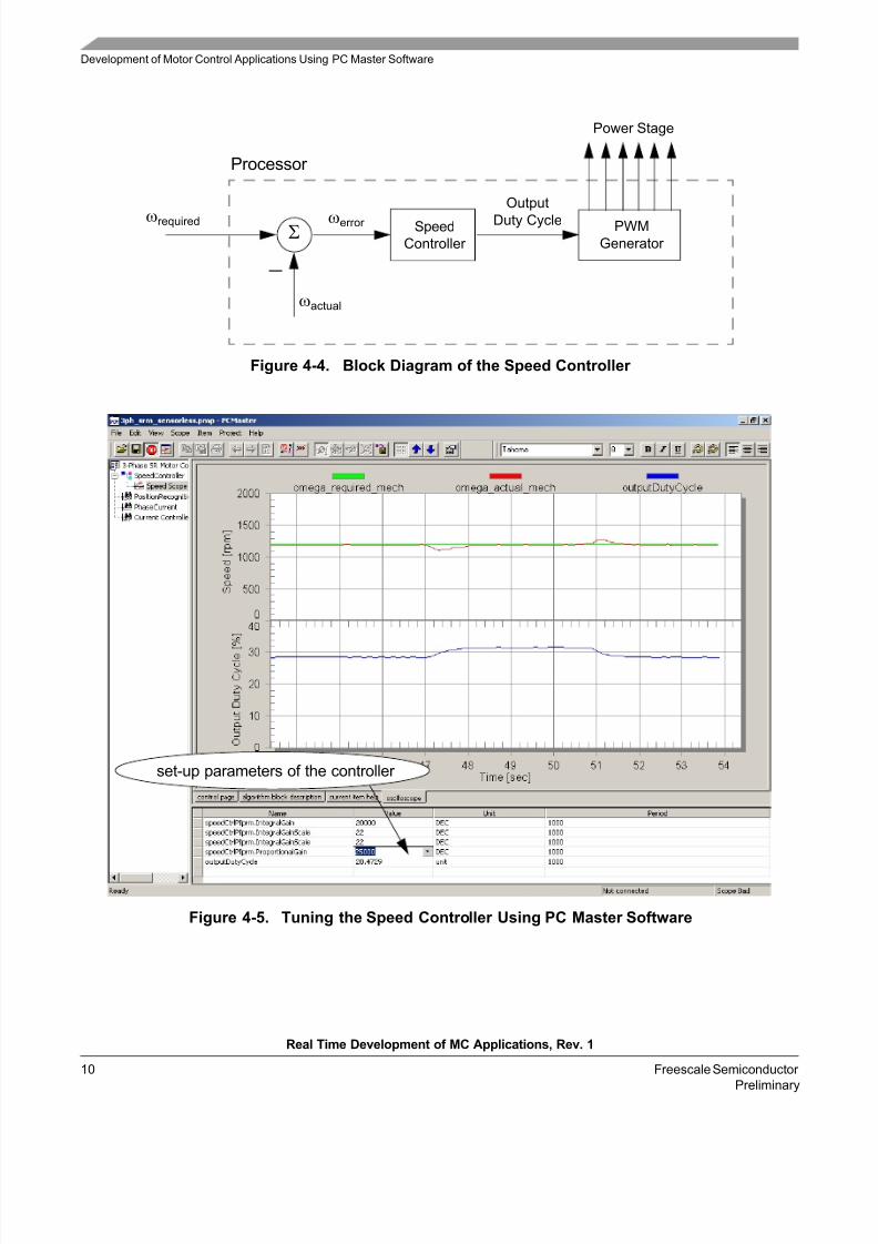
Figure 4-4 and Figure 4-5 show a simple example of tuning a speed controller with help of the PC master software Scope.
8/2/2019 AN1948
http://slidepdf.com/reader/full/an1948 10/16
Σωerror ωrequired
Processor
Speed
Controller
PWM
Generator
Output
Duty Cycle
ωactual
−
Power Stage
Development of Motor Control Applications Using PC Master Software
Real Time Development of MC Applications, Rev. 1
10 Freescale Semiconductor
Preliminary
Figure 4-4. Block Diagram of the Speed Controller
set-up parameters of the controller
Figure 4-5. Tuning the Speed Controller Using PC Master Software

8/2/2019 AN1948
http://slidepdf.com/reader/full/an1948 11/16
On-line Setting of Application Parameters and Variables
Real Time Development of MC Applications, Rev. 1
Freescale Semiconductor 11
Preliminary
The speed controller is a Proportional-Integrational type (PI controller) that evaluates the required speed(ωrequired ) and the actual speed (ωactual ). According to the speed error (ωerror ), it generates the desired outputduty cycle. The Scope window shows the required speed and the actual speed as the input variables, as well asoutput duty cycle as the output variable of the controller (see Figure 4-5). The response of the system to thechange of the motor load is displayed. The Variables window enables on-line change of the individual parameters of the PI controller. The developer can easily evaluate the response of the system and tune the
controller parameters to get the optimal system performance.
4.4 On-line Setting of Application Parameters and Variables
The development of an application often requires setting the application parameters and variables on-line andevaluating the application behavior.
Since PC master software allows the changing of any variable in the memory of the target processor, the task is pretty easy. The developer can read and modify any variable in processor memory. Since any memory variablecan be changed, the developer is fully responsible for changing only the variables that do not cause the systemdamage. The response of the system can be observed either in the Variables window, or with the Scope or Recorder tool.
PC master software allows the simulation of a the selected variable in the time domain using Stimulator. The
Stimulator updates the selected variable automatically according to the table. The stimulated variable is predefined in a simple table as a function of time (see Figure 4-6). Figure 4-7 illustrates the stimulation of thedesired speed and the drive response. The developer can easily evaluate the response of the system to thechange of the variable according to a predefined profile.
Figure 4-6. Setting of Speed Stimulator
As it was mentioned in the PC master software description, the variable can be transformed from the real-type
into more meaningful physical variable. Thus a fractional number from the target processor can be easilytransformed into RPM (speed variables), Volts, Amps, degrees, etc. PC master software also allows theenumeration of the variables. It is useful for displaying the status of the application or algorithm. For examplesof the real type transformation and the enumeration, look at the variables listed in the Variable window inFigure 4-7.

8/2/2019 AN1948
http://slidepdf.com/reader/full/an1948 12/16
Conclusion
Real Time Development of MC Applications, Rev. 1
12 Freescale Semiconductor
Preliminary
Figure 4-7. Stimulation of Desired Speed
5. ConclusionPC master software puts into the developer’s hands a tool that enables development of user’s applicationsmuch faster and efficiently. It enables you “to see” into the target processor without stopping the application.This is extremely important for motor control applications where debugging and tuning needs to be doneon-line during motor operation. It gives the possibility to visualize the course of the selected variables, so thedeveloper can effectively develop the application. The tool enables creation of a demo to control the
application, that can be demonstrated to customers. Overall, the PC master software saves the cost of extremelyexpensive equipment, like multichannel oscilloscopes and current probes. Also, it shortens development timesignificantly. Those who deal with customers remotely will appreciate having the ability to control the
application remotely through the Internet.

8/2/2019 AN1948
http://slidepdf.com/reader/full/an1948 13/16
On-line Setting of Application Parameters and Variables
Real Time Development of MC Applications, Rev. 1
Freescale Semiconductor 13
Preliminary
6. ReferencesThe following materials were used to produce this paper:
[1] 3-Phase SR Sensorless Motor Control Using 56F80x, AN1932, Freescale Semiconductor, Inc.
[2] Connecting Motor Controllers to the Internet, Freescale Semiconductor, Inc.
[3] PC Master Software Communication Protocol Specification, Freescale Semiconductor, Inc.
[4] PC Master Software: Creation of Advanced Control Pages, Freescale Semiconductor, Inc.
[5] PC Master Software Usage, Freescale Semiconductor, Inc.
[6] PC Master Software User’s Manual, included in the SDK documentation, Freescale Semiconductor, Inc.
[7] Software Development Kit including PC master software is available at: www.freescale.com

8/2/2019 AN1948
http://slidepdf.com/reader/full/an1948 14/16
References
Real Time Development of MC Applications, Rev. 1
14 Freescale Semiconductor
Preliminary
8/2/2019 AN1948
http://slidepdf.com/reader/full/an1948 15/16
On-line Setting of Application Parameters and Variables
Real Time Development of MC Applications, Rev. 1
Freescale Semiconductor 15
Preliminary

8/2/2019 AN1948
http://slidepdf.com/reader/full/an1948 16/16
How to Reach Us:
Home Page:www.freescale.com
E-mail:[email protected]
USA/Europe or Locations Not Listed:Freescale Semiconductor Technical Information Center, CH3701300 N. Alma School Road Chandler, Arizona 85224 +1-800-521-6274 or [email protected]
Europe, Middle East, and Africa:Freescale Halbleiter Deutschland GmbHTechnical Information Center Schatzbogen 781829 Muenchen, Germany+44 1296 380 456 (English)+46 8 52200080 (English)+49 89 92103 559 (German)
+33 1 69 35 48 48 (French)[email protected]
Japan:Freescale Semiconductor Japan Ltd. Headquarters
ARCO Tower 15F1-8-1, Shimo-Meguro, Meguro-ku,Tokyo 153-0064, Japan0120 191014 or +81 3 5437 [email protected]
Asia/Pacific:Freescale Semiconductor Hong Kong Ltd.Technical Information Center 2 Dai King Street Tai Po Industrial Estate
Tai Po, N.T., Hong Kong
+800 2666 [email protected]
For Literature Requests Only:Freescale Semiconductor Literature Distribution Center P.O. Box 5405Denver, Colorado 802171-800-441-2447 or 303-675-2140Fax: [email protected]
Freescale™ and the Freescale logo are trademarks of Freescale Semiconductor,
Inc. All other product or service names are the property of their respective owners.
This product incorporates SuperFlash® technology licensed from SST.
© Freescale Semiconductor, Inc. 2005. All rights reserved.
AN1948Rev. 111/2005
Information in this document is provided solely to enable system and
software implementers to use Freescale Semiconductor products. There are
no express or implied copyright licenses granted hereunder to design or
fabricate any integrated circuits or integrated circuits based on the
information in this document.
Freescale Semiconductor reserves the right to make changes without further
notice to any products herein. Freescale Semiconductor makes no warranty,
representation or guarantee regarding the suitability of its products for any
particular purpose, nor does Freescale Semiconductor assume any liability
arising out of the application or use of any product or circuit, and specificallydisclaims any and all liability, including without limitation consequential or
incidental damages. “Typical” parameters that may be provided in Freescale
Semiconductor data sheets and/or specifications can and do vary in different
applications and actual performance may vary over t ime. All operating
parameters, including “Typicals”, must be validated for each customer
application by customer’s technical experts. Freescale Semiconductor does
not convey any license under its patent rights nor the rights of others.
Freescale Semiconductor products are not designed, intended, or authorized
for use as components in systems intended for surgical implant into the body,
or other applications intended to support or sustain life, or for any other
application in which the failure of the Freescale Semiconductor product could
create a situation where personal injury or death may occur. Should Buyer
purchase or use Freescale Semiconductor products for any such unintended
or unauthorized application, Buyer shall indemnify and hold Freescale
Semiconductor and its officers, employees, subsidiaries, affiliates, and
distributors harmless against all claims, costs, damages, and expenses, and
reasonable attorney fees arising out of, directly or indirectly, any claim of
personal injury or death associated with such unintended or unauthorized
use, even if such claim alleges that Freescale Semiconductor was negligentregarding the design or manufacture of the part.