an3312, can bus bootloader for dsc 56f83xx family...
TRANSCRIPT

Freescale SemiconductorApplication Note
Document Number: AN3312Rev. 0, 10/2006
Contents
Overview . . . . . . . . . . . . . . . . . . . . . . . . . . . . . . . . . . . . . 1Introduction . . . . . . . . . . . . . . . . . . . . . . . . . . . . . . . . . . . 2Hardware Requirements . . . . . . . . . . . . . . . . . . . . . . . . . 2FlexCAN . . . . . . . . . . . . . . . . . . . . . . . . . . . . . . . . . . . . . 4FlexCAN Module Configuration . . . . . . . . . . . . . . . . . . . . 5PC-CAN Card Firmware . . . . . . . . . . . . . . . . . . . . . . . . . 6
6.1 Serial Communication Firmware . . . . . . . . . . . . . . . 66.2 Target Board to PC-CAN Card
Communication Firmware . . . . . . . . . . . . . . . . . . . . 86.3 Firmware Downloading Procedures . . . . . . . . . . . . 96.4 S Record Downloading via
PC-CAN Card Procedures. . . . . . . . . . . . . . . . . . . 12
CAN Bus Bootloader for DSC 56F83xx Familyby: Charlie Wu
TSPG — DSPO Application EngineeringKenny LamAPTSPG — 8/16 Bit Application Engineering
1 OverviewThis document describes how to use a Freescale DSC 56F83xx family bootloader to perform an in-circuit re-program of flash memory in a target board. This is done by a CAN bus, a high-speed reliable operation in automotive and industrial control networks.
You will learn how to configure a DSC 56F8345EVM as a PC-CAN card to convert an S-record from the PC to the target board. A laboratory-constructed firmware is also described.
This document is written for users familiar with the DSC 56F83xx family, Metrowerks CodeWarrior for DSP, and CAN protocol, specification, and application. It also provides reference codes that can be modified to specific applications.
123456
© Freescale Semiconductor, Inc., 2006. All rights reserved.

Introduction
2 IntroductionA PC-CAN card is a useful tool for debugging and/or upgrading firmware via the CAN bus, which is built on the target board for communication with its application, thereby not creating additional hardware cost in the system.
The DSC 56F83xx family offers a dedicated flash block (boot flash block) for bootloader, which commonly uses asynchronous communication protocol such as SCI, SPI, and CAN bus to reduce hardware wires. This document guides you in configuring the 56F8346 FlexCAN module for CAN bus communication. The firmware permanently resides in the boot flash block of target board as a CAN bootloader. The bootloader code can be kept even if the power supply is interrupted while programming the 56F8346 internal flash block; however, this performance depends on your hardware.
The application’s firmware is divided into two parts: the PC-CAN card and the target board CAN bootloader. The PC-CAN card firmware also consists of two parts: PC to PC-CAN card communication using RS232, which can be done using the serial bootloader for DSC, and the PC-CAN card to the target board communication via the CAN bus. PC terminal emulator freeware such as Tera Term implements the interface between the PC and PC-CAN card with Xon/Xoff protocol.
The bootloader of the target board configures the FlexCAN module in communication with PC-CAN card through the CAN bus. The bootloader polls the CAN port for messages. After a message is received, the bootloader attempts to decode the incoming commands for flash programming. After the internal flash has successfully downloaded the S-record, the bootloader jumps to the starting address of the new S-record. Figure 1 shows the simple configuration of hardware.
3 Hardware RequirementsThe hardware required for configuration includes:
• Power supply• CAN bus• 56F8346EVB as target board• 56F8346EVB as PC-CAN card. • Terminal firmware for data transfer via RS232
— Bits/sec: 115200— No parity: none— Stop bit: 1— Flow control: Xon/Xoff
CAN Bus Bootloader for DSC 56F83xx Family, Rev. 0
Freescale Semiconductor2

Hardware Requirements
Figure 1. Hardware Configuration
56F8346
56F8346EVM
56F8346
56F8346EVM
56F8346
56F8346EVM
56F8346
56F8346EVM56F8346EVM
56F8346
56F8346EVM
56F8346
56F8346EVM56F8346EVM
56F8346EVB as target board 56F8346EVB as PC-CAN card
Power supply
CAN bus
RS232
CAN Bus Bootloader for DSC 56F83xx Family, Rev. 0
Freescale Semiconductor 3

FlexCAN
4 FlexCANThe FlexCAN (FC) module is a communication controller implementing the controller area network (CAN) protocol, an asynchronous communications protocol used in automotive and industrial control systems. It is a high-speed (1 Mbit/sec), short distance, priority-based protocol able to communicate using a variety of media. The FlexCAN module supports both the standard and extended identifier (ID) message formats specified in the CAN Protocol Revision 2.0 Specification, Part B. The CAN protocol was designed as a vehicle serial data bus, meeting the specific requirements of this field: real-time processing, reliable operation in the EMI environment of a vehicle, cost-effective, and required bandwidth. Knowledge of the CAN protocol, revision 2.0 is assumed. For details, refer to the CAN Protocol Revision 2.0 Specification. Figure 2 shows the FlexCAN module system block diagram.
Figure 2. FlexCAN System Block Diagram
MB15
MB14
MB13
MB12
MB3
MB2
MB1
MB0
0.25 KRAM
Transmit
Receive
Bus Interface Unit
Control
Max MB #(0–15)
CANTX
CANRX
CAN Bus Bootloader for DSC 56F83xx Family, Rev. 0
Freescale Semiconductor4

FlexCAN Module Configuration
5 FlexCAN Module ConfigurationBefore configuring the FlexCAN module, evaluate your system specifications such as system propagation delay (wire length and transceiver delay), crystal tolerance, and re-synchronization jump width. To initialize the FlexCAN registers in CAN communication, you must define parameters such as baud rate, propagation segment (PS), time segment 1 (TS1) and time segment 2 (TS2). Unlike the MSCAN module, the FlexCAN module allows you to define the message buffer (MB) as either receive or transmit by changing the control bit in the corresponding FCMBx_Control register. FCMB0_Control |= 0x0040; // initialize MB0 for receptionFCMB0_Control |= 0x00C8; // initialize MB0 for transmission with 8 bytes in data frame
The basic initialization for the registers:void CanModInit(void){
INT16U timer;
SIM_PCE = SIM_PCE | 0x1000; // enable peripheral clock
FCMCR |= 0x0200; // software reset//initialize all operation modesFCCTL0 |= 0x0001; // PROPSEG = 2TQFCCTL1 = 0x18FF;FCCTL0 &=~ 0x0010; // lowest ID is transmitted firstFCMAXMB = 0x0001; // 2 MBs for use
//initialize message buffer0 FCMB0_Control = 0040; // init MB0 for receptionFCMB0_ID_HIGH = 0x2800; // rec standard frame FCMB0_ID_LOW = 0x0000;FCMB0_DATA0 = 0;FCMB0_DATA1 = 0;FCMB0_DATA2 = 0;FCMB0_DATA3 = 0;
//Initialize message buffer1FCMB1_Control = 0;FCMB1_ID_HIGH = 0;FCMB1_ID_LOW = 0;FCMB1_DATA0 = 0;FCMB1_DATA1 = 0;FCMB1_DATA2 = 0;FCMB1_DATA3 = 0;
//clear HALF bit in FC_MCRFCMCR = 0x0;
//initialize MASK registersFCRXGMASK_H = 0x0000;FCRXGMASK_L = 0x0000;cantx_IDH = 0x1800;
timer = FCTIMER; // Read free running timer to unlock MB}
CAN Bus Bootloader for DSC 56F83xx Family, Rev. 0
Freescale Semiconductor 5

PC-CAN Card Firmware
6 PC-CAN Card FirmwareThe PC-CAN card firmware is divided into two parts: PC to PC-CAN card communication using RS232 (serial communication) and PC-CAN card to target board communication via the CAN bus (PC-CAN Card to target board communication firmware). Figure 3 shows the system block diagram.
Figure 3. PC-CAN System Block Diagram
6.1 Serial Communication FirmwareThe serial communication interface module allows asynchronous serial communication with peripheral devices and other CPUs. It also communicates with PC’s RS232 interface. It requires the RS232 transceiver to connect with DSC 56F8346 TXD0 and TXD1 pins. DSC56F8346EVM is connected to the RS232 transceiver with a 9-pin socket (DTE). It uses a 9-pin serial cable to connect the PC and DSC56F8346EVM. The communication protocol is configured as 115200 bits/sec, with no parity, and one stop bit with Xon/Xoff protocol. The SCI communication was done from serial bootloader (83xx_bootloader.pdf), which helps receive S-records from the PC and stores them in the RAM buffer so they can be transmitted to the target board via the CAN bus. The serial bootloader firmware communicates with the PC through Xon/Xoff protocol and receives the S-record content from PC to DSC56F8346EVM internal buffer array, which is retrieved by “bootMemoryWrite” subroutine for target board.
This firmware also detects whether the internal flash block of the target board is blank. It protects the target board flash, which will not be erased accidentally. Figure 4 shows the flowchart for the firmware starts.
PC
PC-CAN Card
HyperTerminalor
Other Terminal Firmware
RS-232Target Board
CAN Module
Serial Communication Firmware
PC-CAN Card to TargetBoard Communication
Target Board to PC-CAN CardCommunication Firmware
CAN Module
CAN Bus
CAN Bus Bootloader for DSC 56F83xx Family, Rev. 0
Freescale Semiconductor6

PC-CAN Card Firmware
Figure 4. Serial Communication Firmware Starts
Boot Continue
Target Board Flash Erase?
CharBuffer[1] == ‘1’?
CharBuffer[1] == ‘7’?
Target Board Flash Blank?
Start
End
CAN Initialization
Erase Target Board Flash
Send Xon
SCI Initialization
Boot Load S Record
Boot Memory Write
Send Ack to PC
Send Start Frame
Flagflash = TRUE?
Yes
No
No
Yes
No
No
Yes
Yes
YesNo
CAN Bus Bootloader for DSC 56F83xx Family, Rev. 0
Freescale Semiconductor 7

PC-CAN Card Firmware
6.2 Target Board to PC-CAN Card Communication FirmwareThe FlexCAN communication interface module allows an asynchronous communication protocol to and from CAN bus. The target board firmware is located next to the boot flash block. It will be invoked after reset if the state of the hardware pin (Port E bit 7) is set to high. The target board runs its application code if the state of the hardware pin is set to low.
In the target board, the bootloader is held in the DSC for future use. In this application, the bootloader code is running at the boot flash block to receive the data from PC-CAN card firmware through the CAN bus.
Figure 5 shows the flowchart for the firmware starts.
Figure 5. Target Board to PC-CAN Card Firmware Starts
Start
Vector Address = 0and Blank?
Port E Bit 7 = 1No
Yes
CAN Initialization
Yes
canrx_IDH! =ENDFRAME?
No
No
Yes
canrx_IDH! =ADDRFRAME?
bootLoadSRecord
bootMemoryWrite
Send Ack to PC
FlashBlockInitFlag ==ENABLE
canrx_IDH! =PROGFRAME
bootMemoryWrite
LEDInit
Unprotect Prog Flashand Data Flash
Jump to Vector Address 0to Start It’s Application
CAN Tx Setupcantx_IDH = canrx_IDH&~0x1000;cantx_IDH| = 0x2000;can_send_pack2();canTxFlag = DISABLE
Reset Vector ==Blank
cantx_idata[0] =
canrx_IDH! =FLASHREPORT
FRAME
canrx_IDH! =FLASHERASE
FRAME
Erase All Internal Flash
FLASHBLANK
LEDTime =LEDFLASHBLANK
cantx_idata[0] = Reset Vector
canrx_IDH! =STARTADDR
FRAME
StartAddress = camrx_idata
End
No
No
No
No
No
No
Yes
No
Yes
Yes
Yes
Yes
Yes
Yes
CAN Bus Bootloader for DSC 56F83xx Family, Rev. 0
Freescale Semiconductor8

PC-CAN Card Firmware
6.3 Firmware Downloading Procedures1. Download the PC-CAN card firmware.
a) Connect 56F8346EVB as PC-CAN card.
Figure 6. Hardware Configuration—Step 1a
b) Select 56F8346 PC-CAN card as the target project.c) Click the debug icon to download the code to PC-CAN.
Figure 7. Metrowerks CodeWarrior—Steps 1b and 1c
Connect 56F8346EVB as PC-CAN card
56F8357EVB
56F8346JTAG-DSPAXM-0337
RS232
Parallel port cable
56F8357EVB as PC-CAN card
Debugicon
CAN Bus Bootloader for DSC 56F83xx Family, Rev. 0
Freescale Semiconductor 9

PC-CAN Card Firmware
2. Download the target board firmware.a) Connect 56F8346EVB as the target board.
Figure 8. 56F8346EVB as the Target Board
b) Select 56F83456 target CAN.c) Click the debug icon to download the code to the target board.
Figure 9. Metrowerks CodeWarrior—Steps 2a and 2b
Connect 56F8346EVB as target board
56F8346EVB
56F8346JTAG-DSPAXM-0337
RS232
Parallel port cable
56F8357EVB as target board
Debugicon
CAN Bus Bootloader for DSC 56F83xx Family, Rev. 0
Freescale Semiconductor10

PC-CAN Card Firmware
3. Configure hardware.
Figure 10. Hardware Configuration Photo
a) Connect 56F8346EVB (PC-CAN card) to 56F8346EVB (target board).
Figure 11. Hardware Configuration—PC-CAN to Target Board
CAN bus
56F3846EVB as target board 56F3846EVB as PC-CAN board
RS232
56F8346EVB
56F8346
56F8346EVB
56F8346
56F8346EVB as target board 56F8346EVB as PC-CAN card
Terminal firmware for data transferby RS232
Bits/sec: 115200No parity: none
Stop bit: 1Flow control: Xon/Xoff
CAN bus
RS232
CAN Bus Bootloader for DSC 56F83xx Family, Rev. 0
Freescale Semiconductor 11

PC-CAN Card Firmware
6.4 S Record Downloading via PC-CAN Card Procedures1. Invoke Tera Term.
a) Select Serial port.
Figure 12. Tera Term—Step 1a
2. Configure Tera Term. a) Select COM port and the corresponding parameters.
Figure 13. Tera Term—Step 2a
CAN Bus Bootloader for DSC 56F83xx Family, Rev. 0
Freescale Semiconductor12

PC-CAN Card Firmware
3. Send S-record through Tera Term.a) Under the File pull-down menu, select Send file.
Figure 14. Tera Term—Step 3a
b) Use CheckFlash_v2.mcp project to monitor the internal flash data integrity. Select CheckFlash_v2\Debug\56F834x_flash.elf.s and click Open to send the S-record.
Figure 15. Tera Term—Step 3b
CAN Bus Bootloader for DSC 56F83xx Family, Rev. 0
Freescale Semiconductor 13
PC-CAN Card Firmware
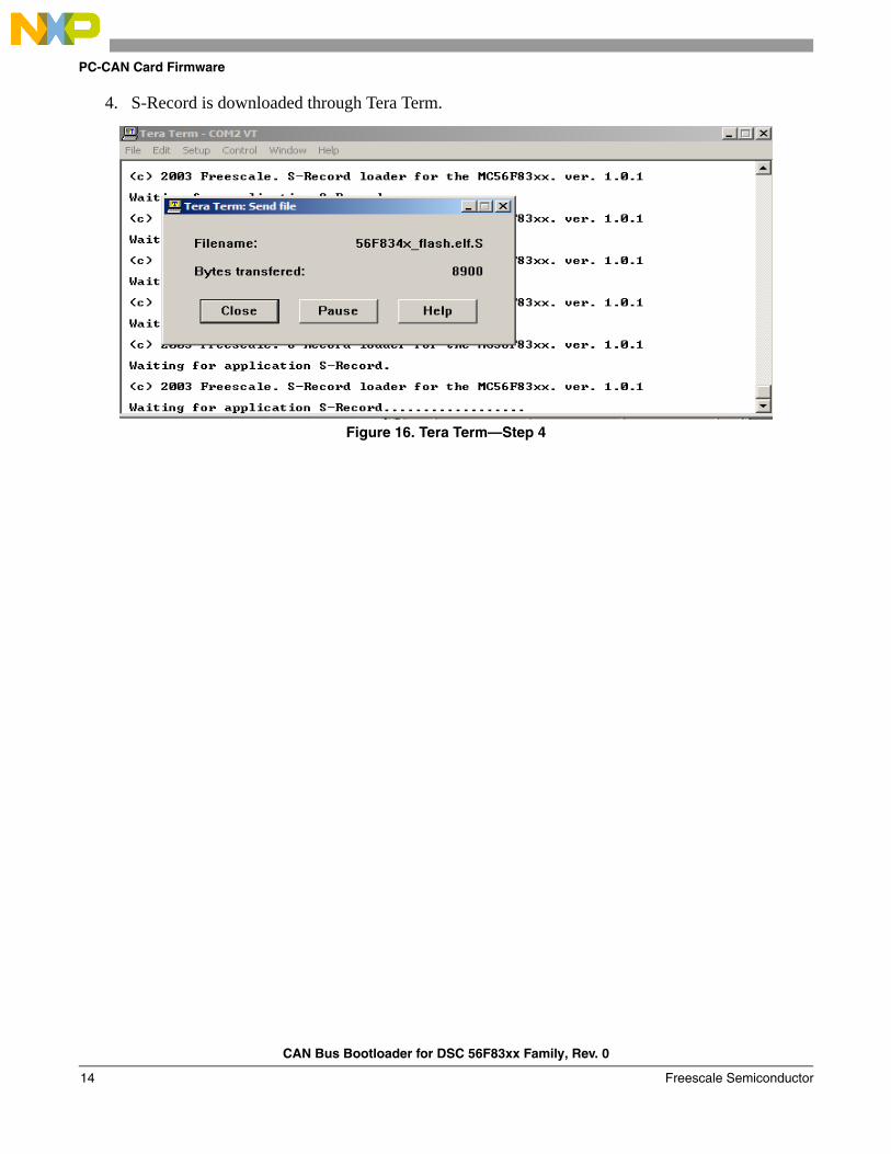
4. S-Record is downloaded through Tera Term.
Figure 16. Tera Term—Step 4
CAN Bus Bootloader for DSC 56F83xx Family, Rev. 0
Freescale Semiconductor14

PC-CAN Card Firmware
5. S-record downloading is complete.
Figure 17. Tera Term—Step 5
a) When the target program is running, the LED (PEC2) blinks to indicate the flash board was verified.
Figure 18. LED Indicator—Step 5aLED indicator
CAN Bus Bootloader for DSC 56F83xx Family, Rev. 0
Freescale Semiconductor 15

PC-CAN Card Firmware
6. During reset, select bootloader in target board.a) Use JG16 (PE7) to select the target board, running internal program flash or internal boot flash.
Select JG16 (1-2) for internal program flash. Select JG16 (2-3) for internal boot flash.
Figure 19. Hardware Configuration—Step 6aJG16 (PE7)
CAN Bus Bootloader for DSC 56F83xx Family, Rev. 0
Freescale Semiconductor16

PC-CAN Card Firmware
7. Use PC-CAN card to erase the target board internal flash.a) Press the reset button of the PC-CAN card to restart PC-CAN card firmware. The symbol “>”
indicates the PC-CAN card will search the target device because the target device is running on its own application code.
b) On the target board, select JG16 (2–3) and press the reset button of the target board to select internal boot flash.
c) The PC-CAN card will stop and display “Target Flash is not blank!! Would you like to erase (Y/N)”
Figure 20. Tera Term—Steps 7a and 7c
CAN Bus Bootloader for DSC 56F83xx Family, Rev. 0
Freescale Semiconductor 17

PC-CAN Card Firmware
8. The PC-CAN card sends the next S-record to the target board.a) Type “y” to erase the internal flash and download again.b) The PC-CAN can repeat the process to download the S-record to other target devices.
Figure 21. Tera Term—Step 8a
The application software, AN3312SW, may be downloaded from the Freescale Web site.
CAN Bus Bootloader for DSC 56F83xx Family, Rev. 0
Freescale Semiconductor18
THIS PAGE IS INTENTIONALLY BLANK
CAN Bus Bootloader for DSC 56F83xx Family, Rev. 0
Freescale Semiconductor 19

Document Number: AN3312Rev. 010/2006
How to Reach Us:
Home Page:www.freescale.com
E-mail:[email protected]
USA/Europe or Locations Not Listed:Freescale SemiconductorTechnical Information Center, CH3701300 N. Alma School RoadChandler, Arizona 85224+1-800-521-6274 or [email protected]
Europe, Middle East, and Africa:Freescale Halbleiter Deutschland GmbHTechnical Information CenterSchatzbogen 781829 Muenchen, Germany+44 1296 380 456 (English)+46 8 52200080 (English)+49 89 92103 559 (German)+33 1 69 35 48 48 (French)[email protected]
Japan:Freescale Semiconductor Japan Ltd.HeadquartersARCO Tower 15F1-8-1, Shimo-Meguro, Meguro-ku,Tokyo 153-0064Japan0120 191014 or +81 3 5437 [email protected]
Asia/Pacific:Freescale Semiconductor Hong Kong Ltd.Technical Information Center2 Dai King StreetTai Po Industrial EstateTai Po, N.T., Hong Kong+800 2666 [email protected]
For Literature Requests Only:Freescale Semiconductor Literature Distribution CenterP.O. Box 5405Denver, Colorado 802171-800-441-2447 or 303-675-2140Fax: [email protected]
Information in this document is provided solely to enable system and software implementers to use Freescale Semiconductor products. There are no express or implied copyright licenses granted hereunder to design or fabricate any integrated circuits or integrated circuits based on the information in this document.
Freescale Semiconductor reserves the right to make changes without further notice to any products herein. Freescale Semiconductor makes no warranty, representation or guarantee regarding the suitability of its products for any particular purpose, nor does Freescale Semiconductor assume any liability arising out of the application or use of any product or circuit, and specifically disclaims any and all liability, including without limitation consequential or incidental damages. “Typical” parameters that may be provided in Freescale Semiconductor data sheets and/or specifications can and do vary in different applications and actual performance may vary over time. All operating parameters, including “Typicals”, must be validated for each customer application by customer’s technical experts. Freescale Semiconductor does not convey any license under its patent rights nor the rights of others. Freescale Semiconductor products are not designed, intended, or authorized for use as components in systems intended for surgical implant into the body, or other applications intended to support or sustain life, or for any other application in which the failure of the Freescale Semiconductor product could create a situation where personal injury or death may occur. Should Buyer purchase or use Freescale Semiconductor products for any such unintended or unauthorized application, Buyer shall indemnify and hold Freescale Semiconductor and its officers, employees, subsidiaries, affiliates, and distributors harmless against all claims, costs, damages, and expenses, and reasonable attorney fees arising out of, directly or indirectly, any claim of personal injury or death associated with such unintended or unauthorized use, even if such claim alleges that Freescale Semiconductor was negligent regarding the design or manufacture of the part.
Freescale™ and the Freescale logo are trademarks of Freescale Semiconductor, Inc. All other product or service names are the property of their respective owners.
© Freescale Semiconductor, Inc. 2006. All rights reserved.
RoHS-compliant and/or Pb-free versions of Freescale products have the functionality and electrical characteristics as their non-RoHS-compliant and/or non-Pb-free counterparts. For further information, see http://www.freescale.com or contact your Freescale sales representative.
For information on Freescale’s Environmental Products program, go to http://www.freescale.com/epp.