anakin club racer english - minigroupshop.minigroup.fr/images/pdf/88871/notice_skh00_260.pdf ·...
TRANSCRIPT

Anakin Club Racer ENGLISH
CONGRATULATIONS on your purchase of a SKY-HERO Anakin Club Racer, we hope that it will provide you with many years of fun and entertainment. SKY-HERO products are designed and developed in Belgium (Europe), but distributed and supported across the globe through a network of dealers and outlets that can provide assistance and advice.
The SKY-HERO ethos is simple; provide cool, flexible, high quality aircraft, and back all products with a fair and reasonable support service
INTRODUCTION
OUR PHILOSOPHY
OUR CONCEPTS
SAFETY ADVICE WARNING!
This aircraft is not a Toy!
All SKY-HERO aircraft can be considered as sophisticated leisure products, which require handling with care and caution in order to avoid injury to yourself or others. Ensure that you fully review all of the information in this instruction manual and familiarise yourself with the characteristics of this SKY-HERO aircraft before attempting to fly it
This instruction manual has been designed with safety in mind and is provided to help you assemble your aircraft and to prepare it for use. Assembly of this aircraft requires basic mechanical and electrical skills and flying this type of aircraft requires basic coordination skills and some practice..
FOLDABLE FRAMES FOR EASIER TRANSPORTATION � PACKNGO
AERODYNAMIC DESIGN PROTECTING ELECTRONICS � SLEEKNSEXY
HEAVY LIFT CAPABILITY WITH GREAT STABILITY � LIFTNSTABLE
RACE BRED MODELS FOR COMPETITION EVENTS � RACENWIN
CUSTOMISABLE AND UPGRADEABLE PLATFORMS � EVOLVENGROW
LEAD THE COMPETITION THROUGH INNOVATION � 1STEPAHEAD
2
• The aircraft should not be flown by children and definitely not by anyone under the age of 14.
• Failure to follow and comply with the safety advice and recommendations in this manual, can result in serious injury to you, others or property.
• You should always check the local laws and regulations of the country where you will operate the aircraft, to ensure you are in compliance with them. In particular you should avoid any sensitive areas such as Military establishments, Airports, Power stations and populated areas.
• Always keep an adequate safe distance around the aircraft, ensuring that you avoid proximity to buildings, people and anything which is outside of your control.
• The aircraft is controlled by radio signal which can be subject to interference outside of your control, a loss of radio contact with the aircraft puts it out of your control and could cause unpredictable results.
• Never fly the aircraft in confined or built up areas, where you might lose visibility of the aircraft.
• Never fly the aircraft in bad weather or strong winds, doing so could cause you to lose control with unpredictable results.
• Never approach the aircraft until the propellers have stopped turning and never try to touch it whilst it is in flight.
• Keep your batteries away from children, young children could attempt to put them in their mouth with dangerous consequences.
• Do not expose the aircraft to water, moisture or liquids.
• Do not attempt to fly the aircraft when battery power is low (including transmitter battery).
• Before each flight, make sure that all propellers are securely attached, that there is no damage to the aircraft or its electronics and wiring.
• Always disconnect the battery power to the aircraft before turning off the transmitter and always turn the transmitter on (checking the position of all controls) before connecting the battery.
• Always following the instructions provided with your Flight Controller and any accessory equipment such as transmitter, battery chargers etc.
GENERAL INSTRUCTIONS AND GUIDELINES FOR USE
3
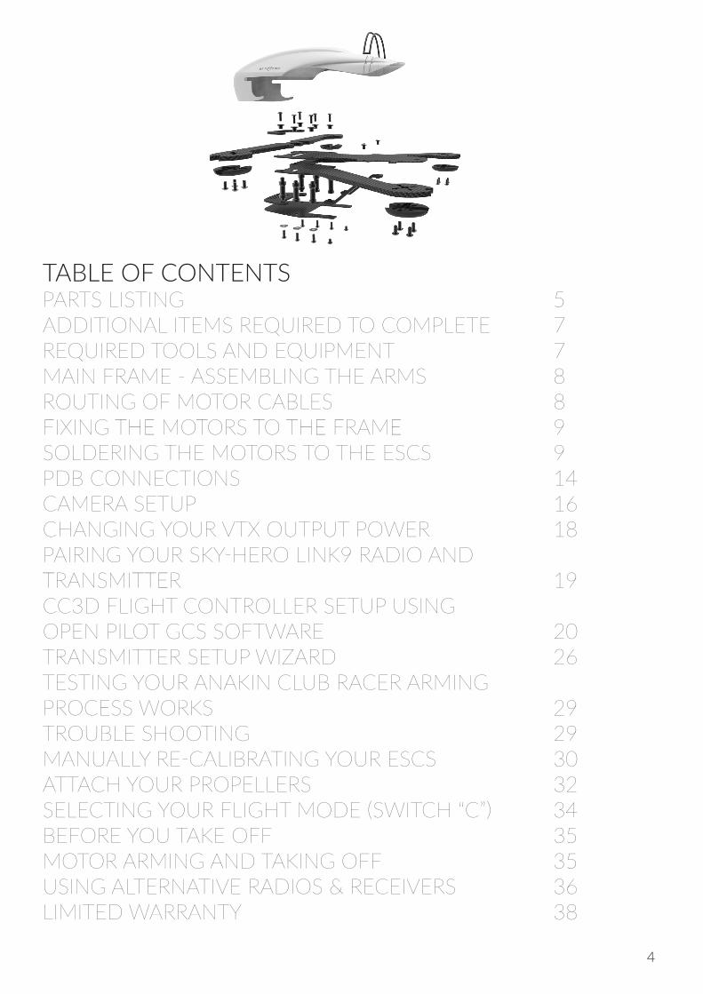
TABLE OF CONTENTSPARTS LISTING 5ADDITIONAL ITEMS REQUIRED TO COMPLETE 7REQUIRED TOOLS AND EQUIPMENT 7 MAIN FRAME - ASSEMBLING THE ARMS 8ROUTING OF MOTOR CABLES 8FIXING THE MOTORS TO THE FRAME 9SOLDERING THE MOTORS TO THE ESCS 9PDB CONNECTIONS 14CAMERA SETUP 16CHANGING YOUR VTX OUTPUT POWER 18PAIRING YOUR SKY-HERO LINK9 RADIO ANDTRANSMITTER 19CC3D FLIGHT CONTROLLER SETUP USING OPEN PILOT GCS SOFTWARE 20TRANSMITTER SETUP WIZARD 26TESTING YOUR ANAKIN CLUB RACER ARMING PROCESS WORKS 29TROUBLE SHOOTING 29MANUALLY RE-CALIBRATING YOUR ESCS 30ATTACH YOUR PROPELLERS 32SELECTING YOUR FLIGHT MODE (SWITCH “C”) 34BEFORE YOU TAKE OFF 35 MOTOR ARMING AND TAKING OFF 35USING ALTERNATIVE RADIOS & RECEIVERS 36LIMITED WARRANTY 38
4
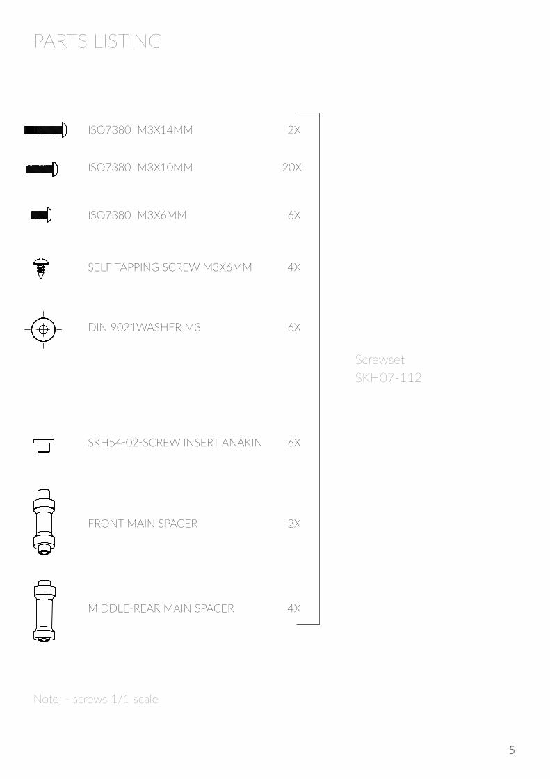
PARTS LISTING
ISO7380 M3X14MM 2X
ISO7380 M3X10MM 20X
ISO7380 M3X6MM 6X
SELF TAPPING SCREW M3X6MM 4X
DIN 9021WASHER M3 6X
SKH54-02-SCREW INSERT ANAKIN 6X
FRONT MAIN SPACER 2X
MIDDLE-REAR MAIN SPACER 4X
ScrewsetSKH07-112
Note: - screws 1/1 scale
5

SKH01-104-Z LED SUPPORTMASSE:
A4
FEUILLE 1 SUR 1ECHELLE:1:1
No. DE PLAN
TITRE:
REVISIONNE PAS CHANGER L'ECHELLE
MATERIAU:
DATESIGNATURENOM
CASSER LESANGLES VIFS
FINITION:SAUF INDICATION CONTRAIRE:LES COTES SONT EN MILLIMETRESETAT DE SURFACE:TOLERANCES: LINEAIRES: ANGULAIRES:
QUAL.
FAB.
APPR.
VERIF.
AUTEUR
OR
OR
6
SKH03-215-F 5"
SKH03-260-F 6"
SKH03-215-R 5" 2X
SKH03-260-R 6" 2X
SKH03-201
SKH05-026
SKH03-201
SKH03-015
SKH03-015
SKH01-107 4X
SKH01-104 2X
SKH05-024-01
SKH03-201
SKH05-024-01MASSE:
A3
FEUILLE 1 SUR 1ECHELLE:1:1
No. DE PLAN
TITRE:
REVISIONNE PAS CHANGER L'ECHELLE
MATERIAU:
DATESIGNATURENOM
CASSER LESANGLES VIFS
FINITION:SAUF INDICATION CONTRAIRE:LES COTES SONT EN MILLIMETRESETAT DE SURFACE:TOLERANCES: LINEAIRES: ANGULAIRES:
QUAL.
FAB.
APPR.
VERIF.
AUTEUR
ADDITIONAL ITEMS REQUIRED TO COMPLETE (with our recommendations)
Radio Transmitter & Receiver • Link9 Mode 1 Radio & Receiver - SKH02-001-M1 • Link9 Mode 2 Radio & Receiver - SKH02-001
Power Distribution Board • PDB + 5V BEC - SKH04-026
Motors (quantity x4) • X-NOVA 2204 (for 5" Anakin Club Racer) - SKH04-028 • X-NOVA 2206 (for 6" Anakin Club Racer) - SKH04-022
Esc’s • Littlebee 12-20A (2-4S) - SKH04-025
3-4S Lipo Battery and a Battery retaining strap • Anakin Lipo 3S 1300mAh 35C – SKH08-012 • Anakin Lipo 3S 1300mAh 65C – SKH08-013 • LIPO 4S 1300mAh 65C – SKH08-014 • LIPO 4S 1800mAh 65C – SKH08-020 (6” Club Racer model only)
Video Transmitter (for camera and FPV use) • VTX 25-200mW 40CH Race Band SKH04-019
Battery connector and plug
Battery strap
REQUIRED TOOLS AND EQUIPMENT • Soldering Iron • Double sided adhesive Tape • 2mm Hex Screwdriver • 8mm Spanner • 15mm Heat shrink Tubing (20 cm length) • Male Futaba Servo type plug (with approximately 5cm of positive and negative wires connected)
The following instructions assume that you are using Sky-Hero components (Camera, VTX and Radio equipment), however towards the end of the manual there is also some basic information over the use of alternative equipment
7
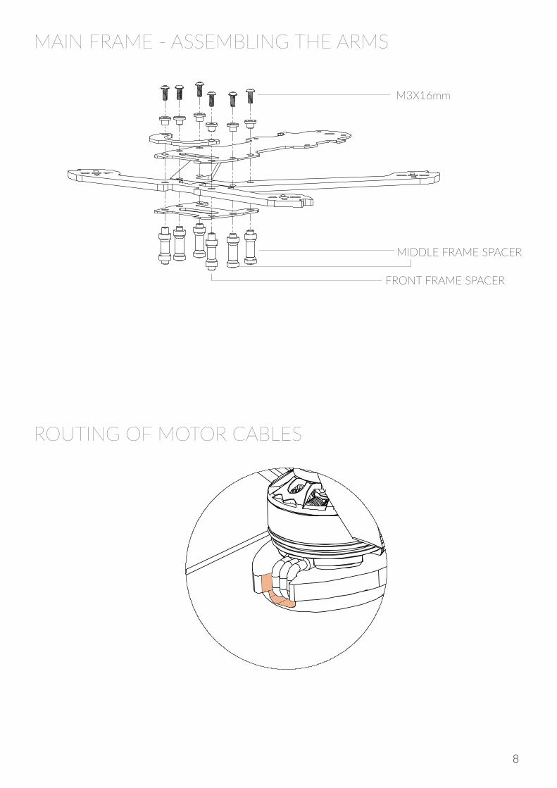
MAIN FRAME - ASSEMBLING THE ARMS
ROUTING OF MOTOR CABLES
A
B
DÉTAIL A ECHELLE 2 : 1
DÉTAIL B ECHELLE 2 : 1
M3X16mm
MIDDLE FRAME SPACER
FRONT FRAME SPACER
8
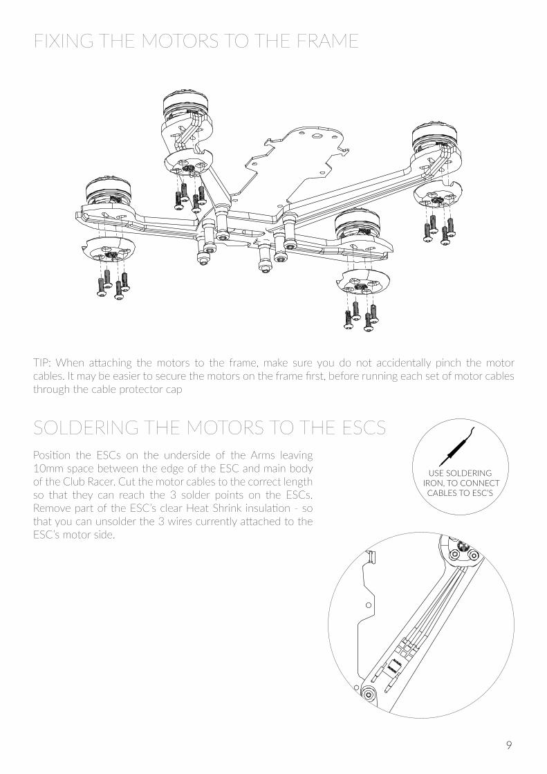
FIXING THE MOTORS TO THE FRAME
SOLDERING THE MOTORS TO THE ESCS
TIP: When attaching the motors to the frame, make sure you do not accidentally pinch the motor cables. It may be easier to secure the motors on the frame first, before running each set of motor cables through the cable protector cap
USE SOLDERING IRON, TO CONNECT
CABLES TO ESC’S
Position the ESCs on the underside of the Arms leaving 10mm space between the edge of the ESC and main body of the Club Racer. Cut the motor cables to the correct length so that they can reach the 3 solder points on the ESCs. Remove part of the ESC’s clear Heat Shrink insulation - so that you can unsolder the 3 wires currently attached to the ESC’s motor side.
9
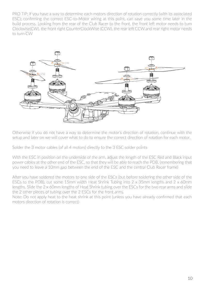
PRO TIP: If you have a way to determine each motors direction of rotation correctly (with its associated ESC); confirming the correct ESC-to-Motor wiring at this point, can save you some time later in the build process. Looking from the rear of the Club Racer to the front, the front left motor needs to turn Clockwise(CW), the front right CounterClockWise (CCW), the rear left CCW and rear right motor needs to turn CW
Otherwise if you do not have a way to determine the motor’s direction of rotation, continue with the setup and later on we will cover what to do to ensure the correct direction of rotation for each motor.
Solder the 3 motor cables (of all 4 motors) directly to the 3 ESC solder points
With the ESC in position on the underside of the arm, adjust the length of the ESC Red and Black input power cables at the other end of the ESC, so that they will be able to reach the PDB, (remembering that you need to leave a 10mm gap between the end of the ESC and the central Club Racer frame)
After you have soldered the motors to one side of the ESCs (but before soldering the other side of the ESCs to the PDB), cut some 15mm width Heat Shrink Tubing into 2 x 35mm lengths and 2 x 60mm lengths. Slide the 2 x 60mm lengths of Heat Shrink tubing over the ESCs for the two rear arms and slide the 2 other pieces of tubing over the 2 ESCs for the front arms. Note: Do not apply heat to the heat shrink at this point (unless you have already confirmed that each motors direction of rotation is correct)
CW
CCW
CCW
CW
10
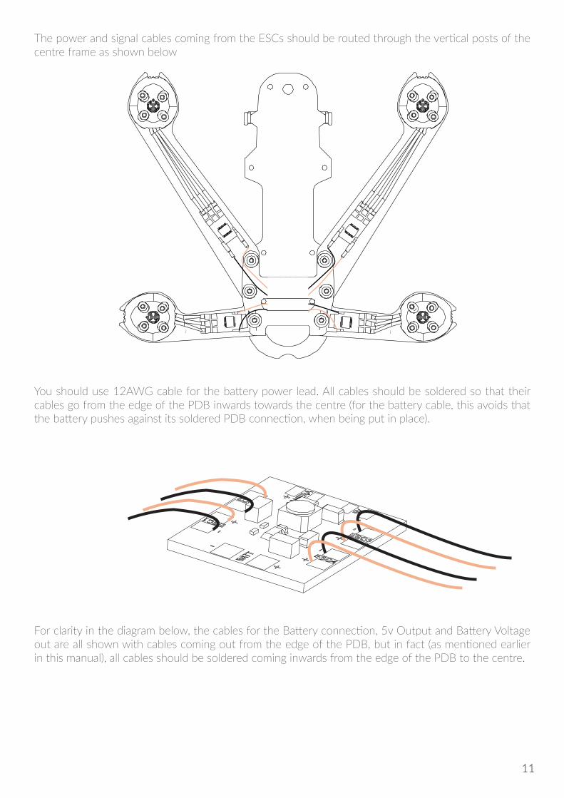
The power and signal cables coming from the ESCs should be routed through the vertical posts of the centre frame as shown below
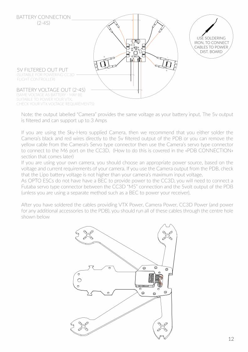
You should use 12AWG cable for the battery power lead. All cables should be soldered so that their cables go from the edge of the PDB inwards towards the centre (for the battery cable, this avoids that the battery pushes against its soldered PDB connection, when being put in place).
For clarity in the diagram below, the cables for the Battery connection, 5v Output and Battery Voltage out are all shown with cables coming out from the edge of the PDB, but in fact (as mentioned earlier in this manual), all cables should be soldered coming inwards from the edge of the PDB to the centre.
11
+
+
+
-
-
-
-
+
USE SOLDERING IRON, TO CONNECT CABLES TO POWER
DIST. BOARD
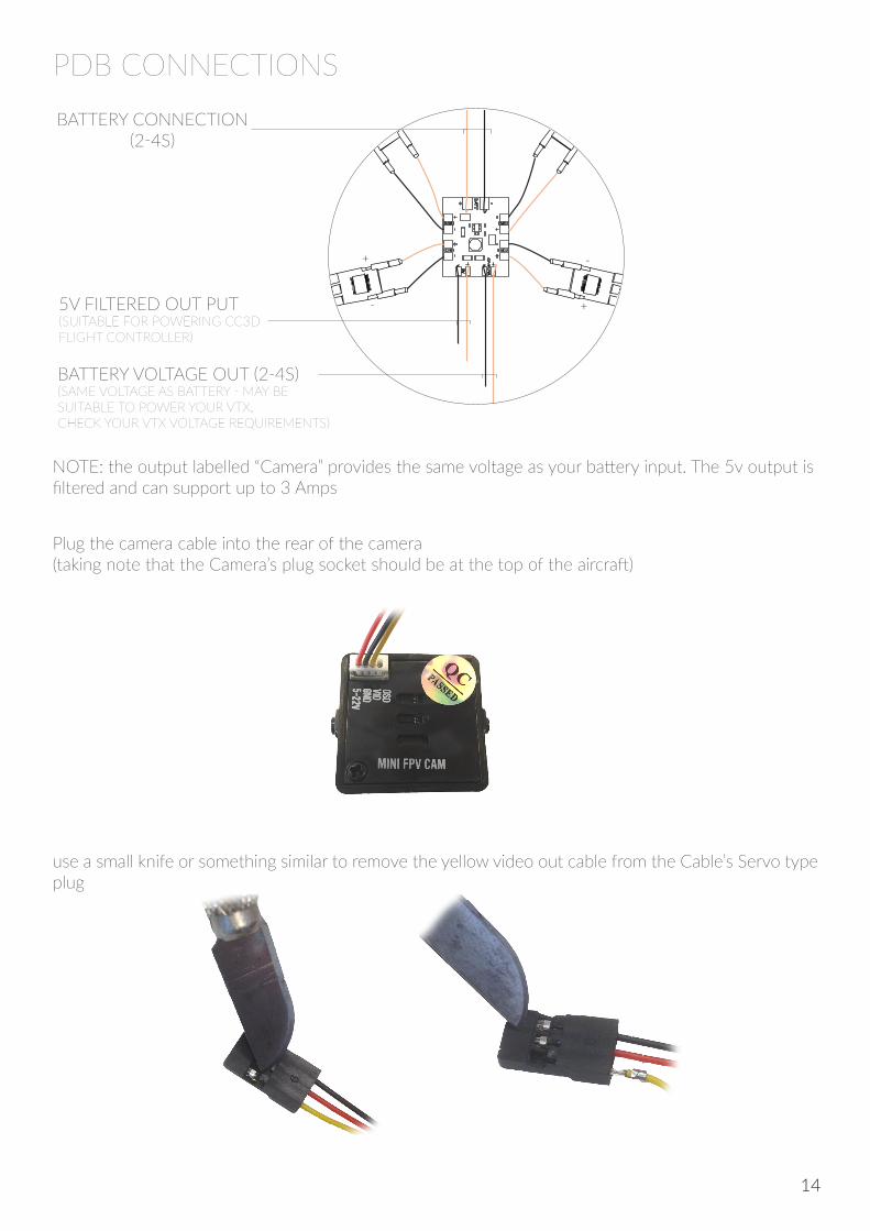
BATTERY VOLTAGE OUT (2-4S)(SAME VOLTAGE AS BATTERY - MAY BE SUITABLE TO POWER YOUR VTX, CHECK YOUR VTX VOLTAGE REQUIREMENTS)
5V FILTERED OUT PUT(SUITABLE FOR POWERING CC3D FLIGHT CONTROLLER)
BATTERY CONNECTION(2-4S)
Note: the output labelled “Camera” provides the same voltage as your battery input. The 5v output is filtered and can support up to 3 Amps If you are using the Sky-Hero supplied Camera, then we recommend that you either solder the Camera’s black and red wires directly to the 5v filtered output of the PDB or you can remove the yellow cable from the Camera’s Servo type connector then use the Camera’s servo type connector to connect to the M6 port on the CC3D. (How to do this is covered in the «PDB CONNECTION» section that comes later)If you are using your own camera, you should choose an appropriate power source, based on the voltage and current requirements of your camera. If you use the Camera output from the PDB, check that the Lipo battery voltage is not higher than your camera’s maximum input voltage.As OPTO ESCs do not have have a BEC to provide power to the CC3D, you will need to connect a Futaba servo type connector between the CC3D “M5” connection and the 5volt output of the PDB (unless you are using a separate method such as a BEC to power your receiver).
After you have soldered the cables providing VTX Power, Camera Power, CC3D Power (and power for any additional accessories to the PDB), you should run all of these cables through the centre hole shown below
12
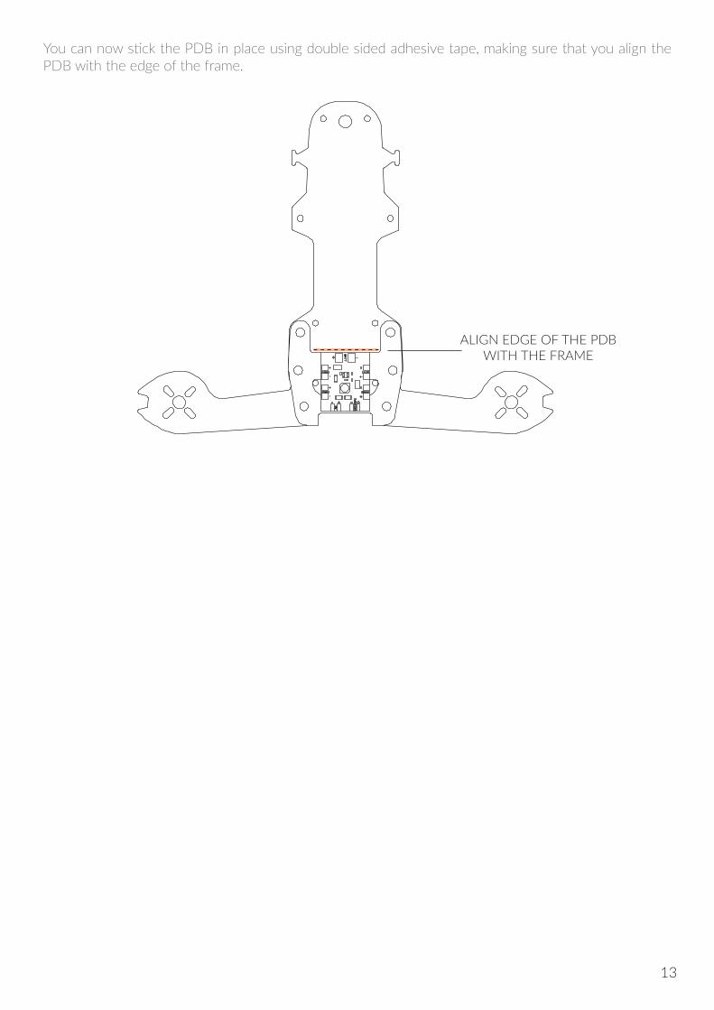
ALIGN EDGE OF THE PDB WITH THE FRAME
You can now stick the PDB in place using double sided adhesive tape, making sure that you align the PDB with the edge of the frame.
13
PDB CONNECTIONS
+
+
+
-
-
-
-
+
BATTERY VOLTAGE OUT (2-4S)(SAME VOLTAGE AS BATTERY - MAY BE SUITABLE TO POWER YOUR VTX, CHECK YOUR VTX VOLTAGE REQUIREMENTS)
5V FILTERED OUT PUT(SUITABLE FOR POWERING CC3D FLIGHT CONTROLLER)
BATTERY CONNECTION(2-4S)
NOTE: the output labelled “Camera” provides the same voltage as your battery input. The 5v output is filtered and can support up to 3 Amps
Plug the camera cable into the rear of the camera (taking note that the Camera’s plug socket should be at the top of the aircraft)
use a small knife or something similar to remove the yellow video out cable from the Cable’s Servo type plug
14
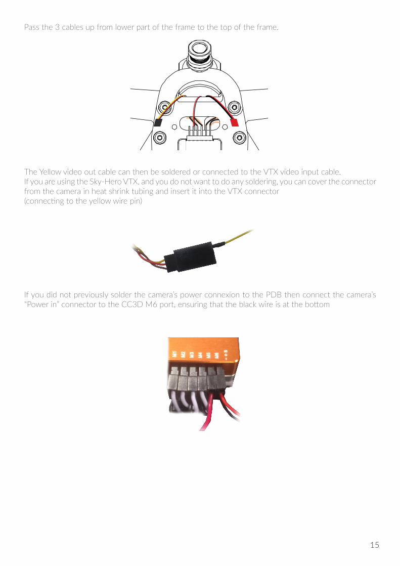
Pass the 3 cables up from lower part of the frame to the top of the frame.
The Yellow video out cable can then be soldered or connected to the VTX video input cable. If you are using the Sky-Hero VTX, and you do not want to do any soldering, you can cover the connector from the camera in heat shrink tubing and insert it into the VTX connector (connecting to the yellow wire pin)
If you did not previously solder the camera’s power connexion to the PDB then connect the camera’s “Power in” connector to the CC3D M6 port, ensuring that the black wire is at the bottom
15
In order to make fine adjustments to your camera angle, it may be necessary to slightly ream out (deepen the size of) the grooves in the adjustable lower camera plate (this can be done using a small file or drill)
NOTE: You can remove the camera at any point to adjust its position by slightly unscrewing the two bolts holding the curved bracket above the camera
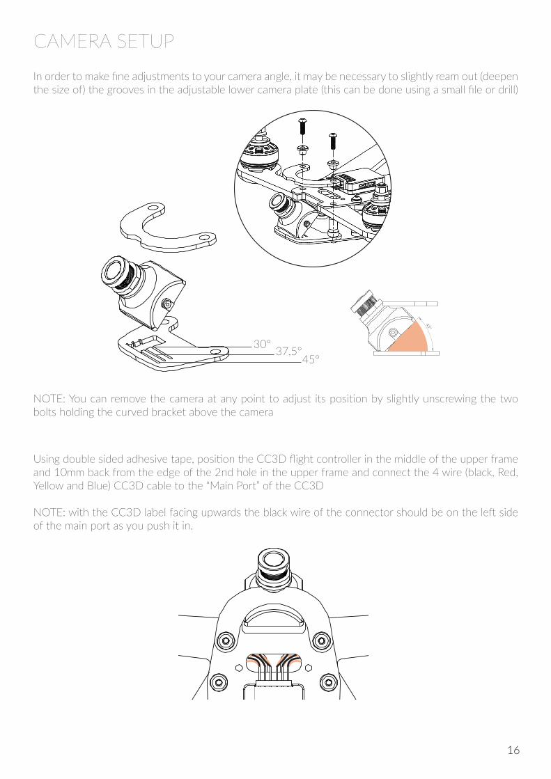
Using double sided adhesive tape, position the CC3D flight controller in the middle of the upper frame and 10mm back from the edge of the 2nd hole in the upper frame and connect the 4 wire (black, Red, Yellow and Blue) CC3D cable to the “Main Port” of the CC3D
NOTE: with the CC3D label facing upwards the black wire of the connector should be on the left side of the main port as you push it in.
45°
45°37,5°30°
CAMERA SETUP
16
Next step is to use double sided adhesive tape to position the Link9 Radio Receiver behind the CC3D Flight Controller as shown in diagram below.
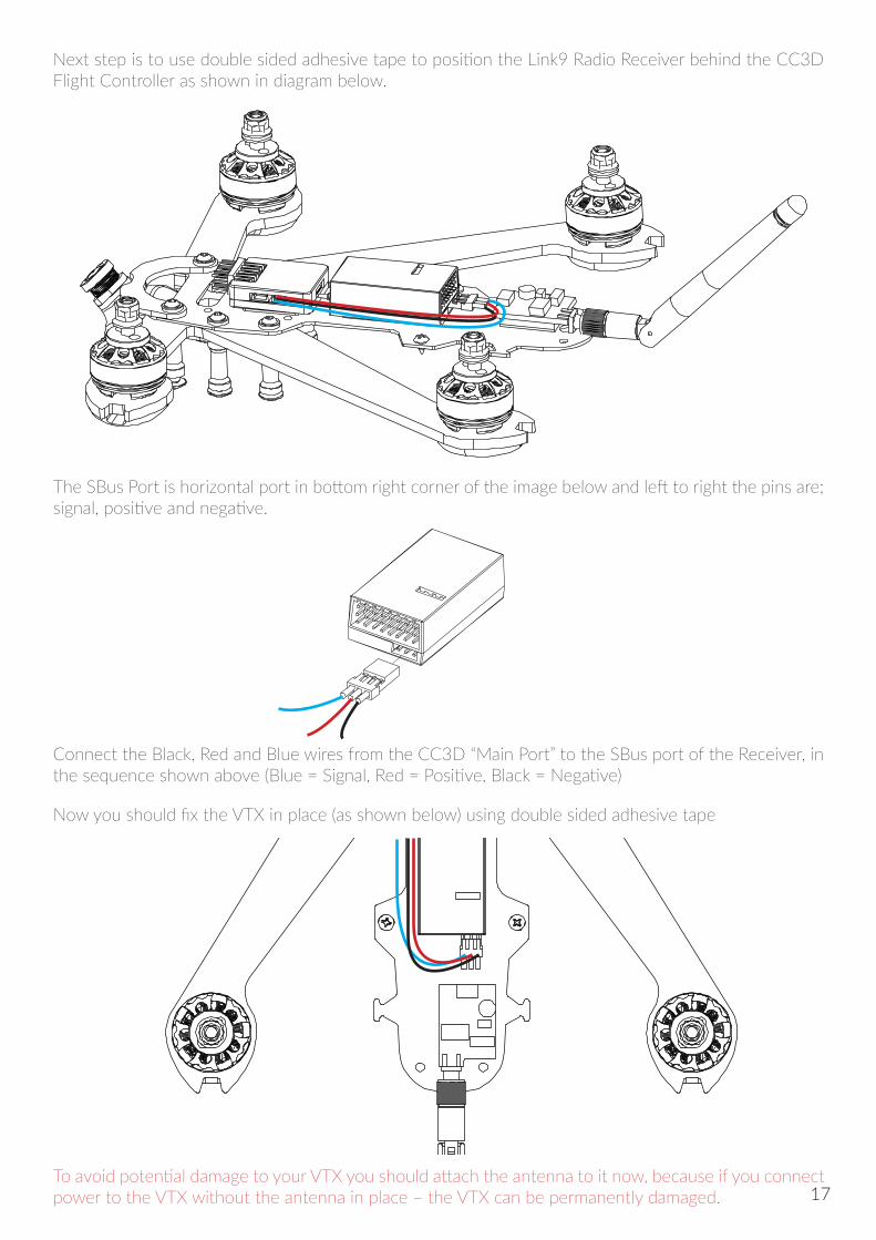
The SBus Port is horizontal port in bottom right corner of the image below and left to right the pins are; signal, positive and negative.
Connect the Black, Red and Blue wires from the CC3D “Main Port” to the SBus port of the Receiver, in the sequence shown above (Blue = Signal, Red = Positive, Black = Negative)
Now you should fix the VTX in place (as shown below) using double sided adhesive tape
To avoid potential damage to your VTX you should attach the antenna to it now, because if you connect power to the VTX without the antenna in place – the VTX can be permanently damaged. 17
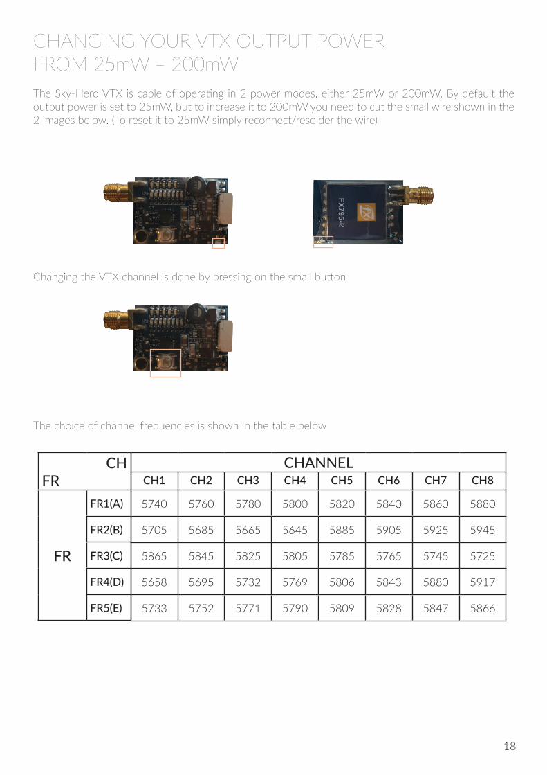
CHANGING YOUR VTX OUTPUT POWER FROM 25mW – 200mWThe Sky-Hero VTX is cable of operating in 2 power modes, either 25mW or 200mW. By default the output power is set to 25mW, but to increase it to 200mW you need to cut the small wire shown in the 2 images below. (To reset it to 25mW simply reconnect/resolder the wire)
Changing the VTX channel is done by pressing on the small button
The choice of channel frequencies is shown in the table below
CHFR
FR
FR1(A)
FR2(B)
FR3(C)
FR4(D)
FR5(E)
CHANNELCH1 CH2 CH3 CH4 CH5 CH6 CH7 CH8
5740 5760 5780 5800 5820 5840 5860 5880
5705 5685 5665 5645 5885 5905 5925 5945
5865 5845 5825 5805 5785 5765 5745 5725
5658 5695 5732 5769 5806 5843 5880 5917
5733 5752 5771 5790 5809 5828 5847 5866
2
18
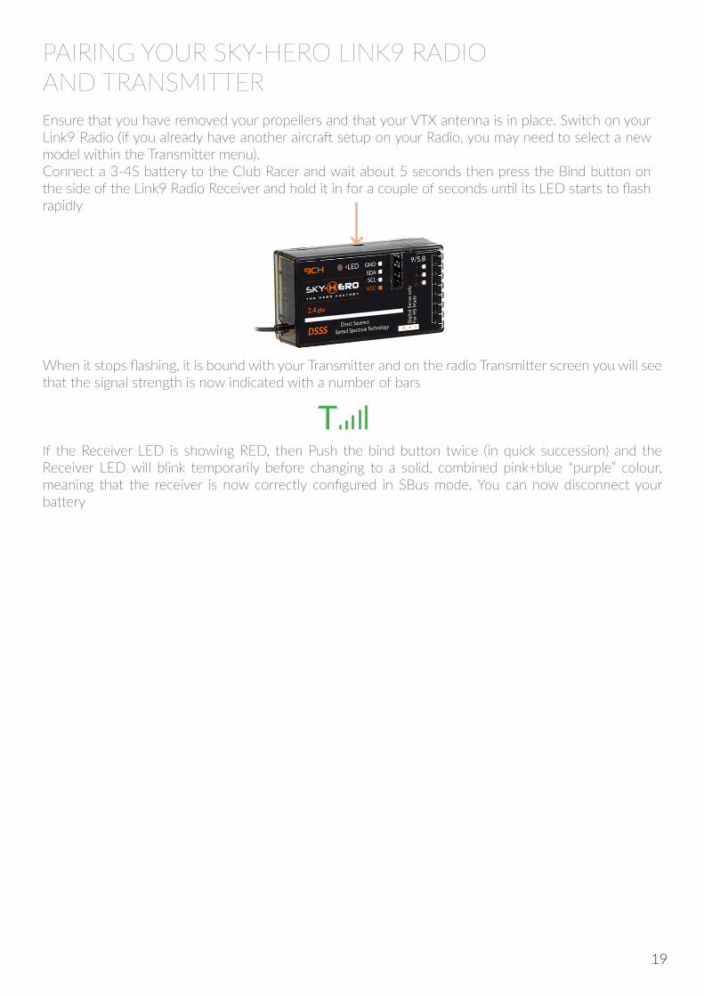
PAIRING YOUR SKY-HERO LINK9 RADIOAND TRANSMITTEREnsure that you have removed your propellers and that your VTX antenna is in place. Switch on your Link9 Radio (if you already have another aircraft setup on your Radio, you may need to select a new model within the Transmitter menu).Connect a 3-4S battery to the Club Racer and wait about 5 seconds then press the Bind button on the side of the Link9 Radio Receiver and hold it in for a couple of seconds until its LED starts to flash rapidly
When it stops flashing, it is bound with your Transmitter and on the radio Transmitter screen you will see that the signal strength is now indicated with a number of bars
If the Receiver LED is showing RED, then Push the bind button twice (in quick succession) and the Receiver LED will blink temporarily before changing to a solid, combined pink+blue “purple” colour, meaning that the receiver is now correctly configured in SBus mode. You can now disconnect your battery
T
19
CC3D FLIGHT CONTROLLER SETUP USING OPEN PILOT GCS SOFTWARE
WARNING! Make sure you have removed your propellers before starting this section!
This instruction is for setting up the CC3D flight controller that comes with your Club Racer ARF with the Link9 Radio/Receiver and using the OpenPilot GCS software for the Microsoft Windows platform. If you are not using the Sky-Hero Link 9 radio with its receiver go to page 28
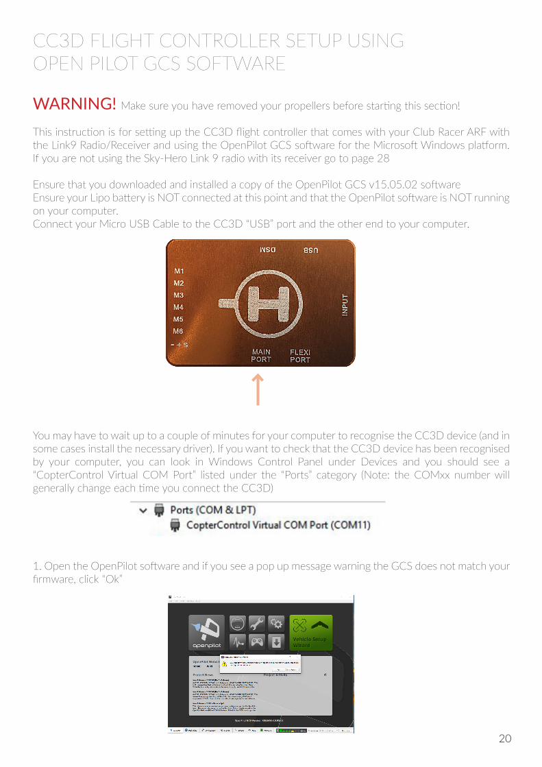
Ensure that you downloaded and installed a copy of the OpenPilot GCS v15.05.02 softwareEnsure your Lipo battery is NOT connected at this point and that the OpenPilot software is NOT running on your computer. Connect your Micro USB Cable to the CC3D “USB” port and the other end to your computer.
1. Open the OpenPilot software and if you see a pop up message warning the GCS does not match your firmware, click “Ok”
You may have to wait up to a couple of minutes for your computer to recognise the CC3D device (and in some cases install the necessary driver). If you want to check that the CC3D device has been recognised by your computer, you can look in Windows Control Panel under Devices and you should see a “CopterControl Virtual COM Port” listed under the “Ports” category (Note: the COMxx number will generally change each time you connect the CC3D)
20
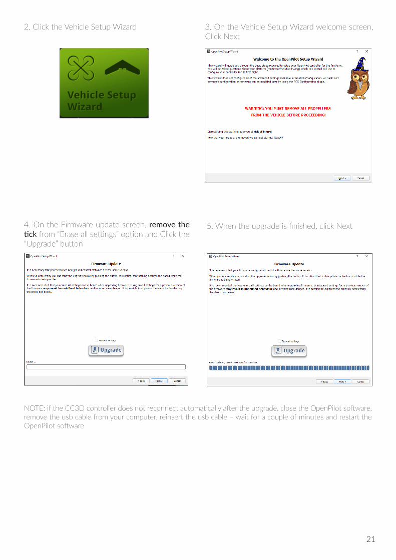
2. Click the Vehicle Setup Wizard 3. On the Vehicle Setup Wizard welcome screen, Click Next
5. When the upgrade is finished, click Next4. On the Firmware update screen, remove the tick from “Erase all settings” option and Click the “Upgrade” button
NOTE: if the CC3D controller does not reconnect automatically after the upgrade, close the OpenPilot software, remove the usb cable from your computer, reinsert the usb cable – wait for a couple of minutes and restart the OpenPilot software
21
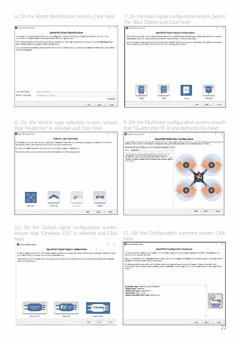
6. On the Board Identification screen, Click Next 7. On the Input signal configuration screen, Select the SBus Option and Click Next
8. On the Vehicle type selection screen, ensure that “Multirotor” is selected and Click Next
9. On the Multirotor configuration screen, ensure that “Quadcopter X” is selected and click Next
10. On the Output signal configuration screen, ensure that “Oneshot 125” is selected and Click Next
11. On the Configuration summary screen, Click Next
22
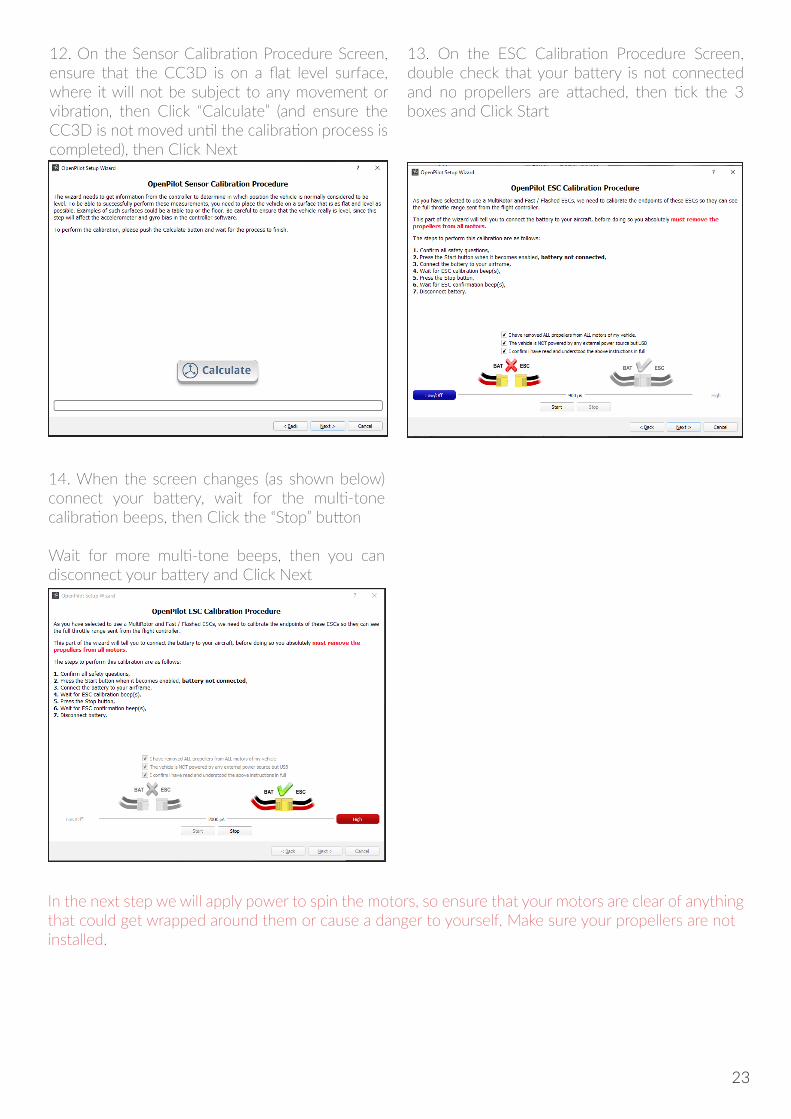
12. On the Sensor Calibration Procedure Screen, ensure that the CC3D is on a flat level surface, where it will not be subject to any movement or vibration, then Click “Calculate” (and ensure the CC3D is not moved until the calibration process is completed), then Click Next
13. On the ESC Calibration Procedure Screen, double check that your battery is not connected and no propellers are attached, then tick the 3 boxes and Click Start
In the next step we will apply power to spin the motors, so ensure that your motors are clear of anything that could get wrapped around them or cause a danger to yourself. Make sure your propellers are not installed.
14. When the screen changes (as shown below) connect your battery, wait for the multi-tone calibration beeps, then Click the “Stop” button
Wait for more multi-tone beeps, then you can disconnect your battery and Click Next
23
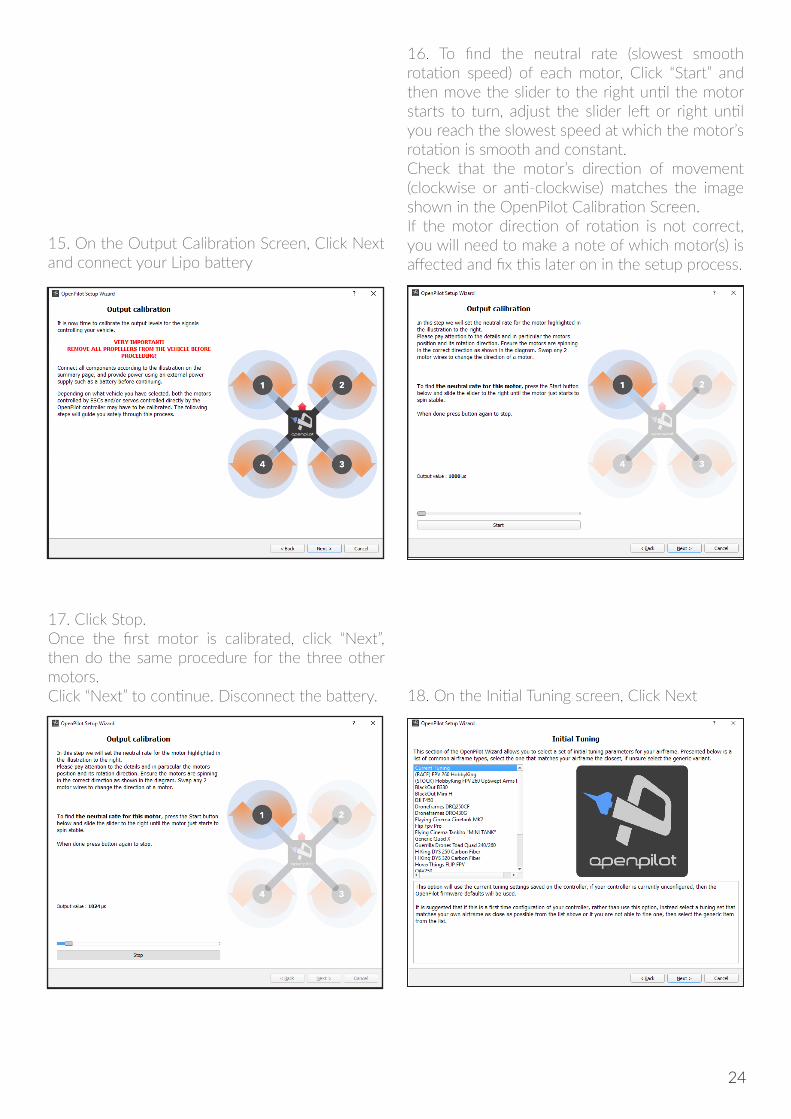
15. On the Output Calibration Screen, Click Next and connect your Lipo battery
17. Click Stop.Once the first motor is calibrated, click “Next”, then do the same procedure for the three other motors. Click “Next” to continue. Disconnect the battery. 18. On the Initial Tuning screen, Click Next
16. To find the neutral rate (slowest smooth rotation speed) of each motor, Click “Start” and then move the slider to the right until the motor starts to turn, adjust the slider left or right until you reach the slowest speed at which the motor’s rotation is smooth and constant.Check that the motor’s direction of movement (clockwise or anti-clockwise) matches the image shown in the OpenPilot Calibration Screen. If the motor direction of rotation is not correct, you will need to make a note of which motor(s) is affected and fix this later on in the setup process.
24
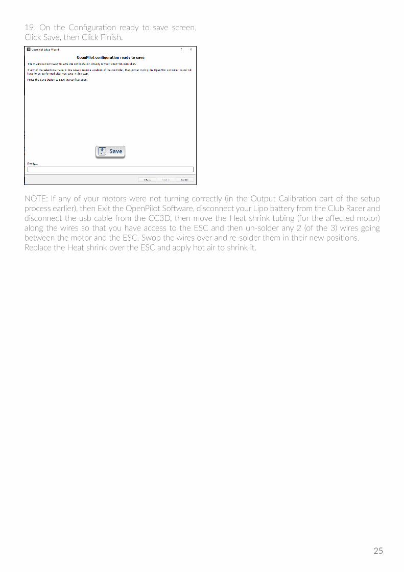
19. On the Configuration ready to save screen, Click Save, then Click Finish.
NOTE: If any of your motors were not turning correctly (in the Output Calibration part of the setup process earlier), then Exit the OpenPilot Software, disconnect your Lipo battery from the Club Racer and disconnect the usb cable from the CC3D, then move the Heat shrink tubing (for the affected motor) along the wires so that you have access to the ESC and then un-solder any 2 (of the 3) wires going between the motor and the ESC. Swop the wires over and re-solder them in their new positions.Replace the Heat shrink over the ESC and apply hot air to shrink it.
25
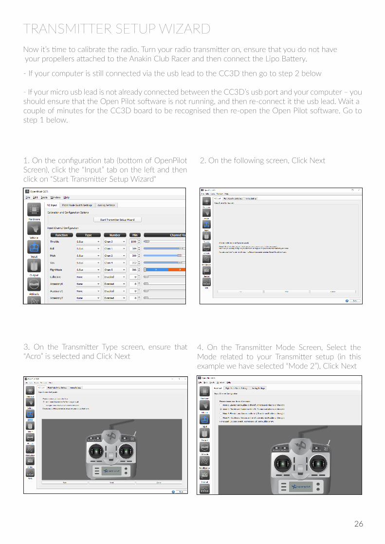
2. On the following screen, Click Next1. On the configuration tab (bottom of OpenPilot Screen), click the “Input” tab on the left and then click on “Start Transmitter Setup Wizard“
4. On the Transmitter Mode Screen, Select the Mode related to your Transmitter setup (in this example we have selected “Mode 2”), Click Next
3. On the Transmitter Type screen, ensure that “Acro” is selected and Click Next
TRANSMITTER SETUP WIZARDNow it’s time to calibrate the radio. Turn your radio transmitter on, ensure that you do not have your propellers attached to the Anakin Club Racer and then connect the Lipo Battery.
- If your computer is still connected via the usb lead to the CC3D then go to step 2 below
- If your micro usb lead is not already connected between the CC3D’s usb port and your computer – youshould ensure that the Open Pilot software is not running, and then re-connect it the usb lead. Wait acouple of minutes for the CC3D board to be recognised then re-open the Open Pilot software. Go to step 1 below.
26
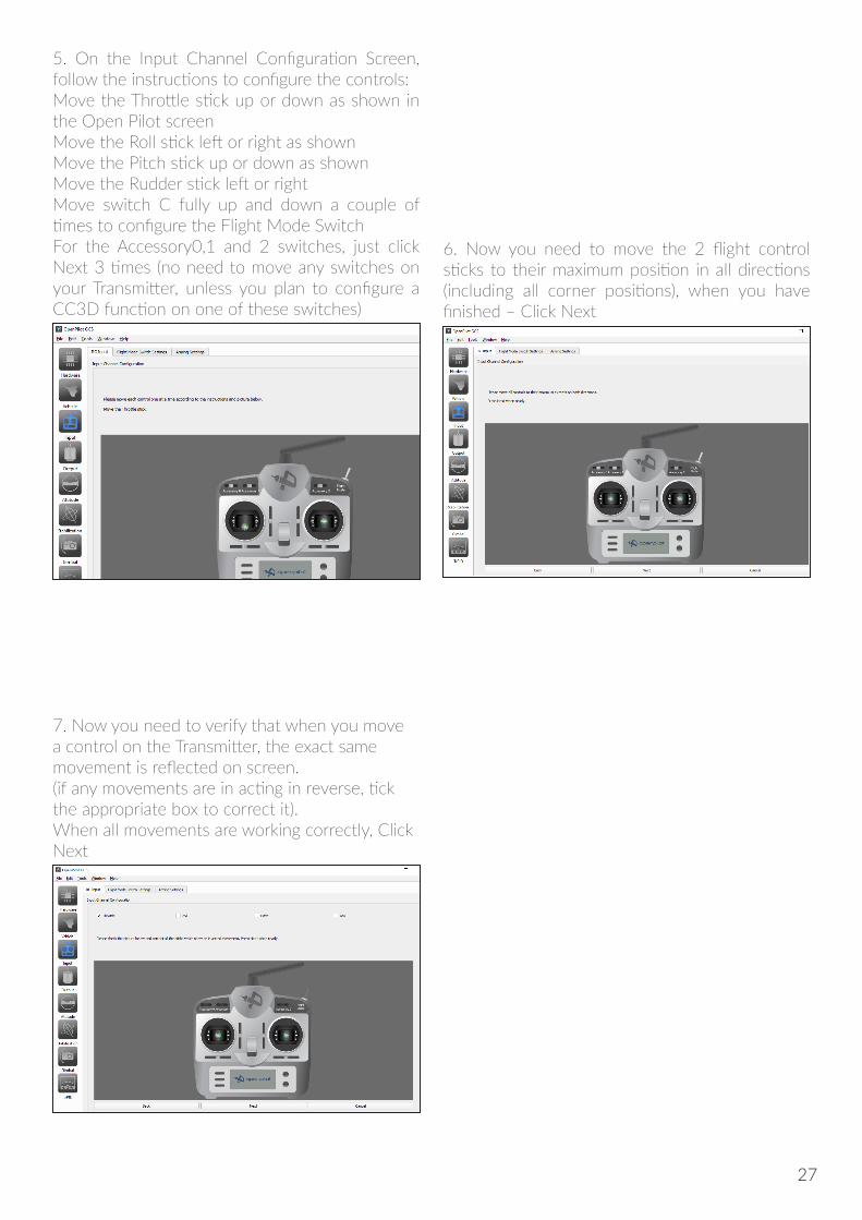
5. On the Input Channel Configuration Screen, follow the instructions to configure the controls:Move the Throttle stick up or down as shown in the Open Pilot screenMove the Roll stick left or right as shown Move the Pitch stick up or down as shownMove the Rudder stick left or rightMove switch C fully up and down a couple of times to configure the Flight Mode SwitchFor the Accessory0,1 and 2 switches, just click Next 3 times (no need to move any switches on your Transmitter, unless you plan to configure a CC3D function on one of these switches)
6. Now you need to move the 2 flight control sticks to their maximum position in all directions (including all corner positions), when you have finished – Click Next
7. Now you need to verify that when you move a control on the Transmitter, the exact same movement is reflected on screen. (if any movements are in acting in reverse, tick the appropriate box to correct it). When all movements are working correctly, Click Next
27
The change in step 10 above, is very important and failing to do so, will make your Anakin Club Racer impossible to fly as the controls will appear to operate in reverse. (In order to have optimal cable connections, the CC3D is actually mounted in reverse with its front pointing to the rear)
PLEASE DO NOT MODIFY THESE CC3D SETTINGS UNLESS YOU ARE FAMILIAR WITH CC3DTUNING AND YOU FULLY UNDERSTAND WHAT YOU ARE DOING. MISCONFIGURATION OFTHE CC3D CONTROLLER MAY CAUSE HARDWARE ISSUES WHICH CAN NOT BE REPAIRED
BY THE END USER AND WOULD ALSO VOID YOUR SKY-HERO WARRANTY
Exit (close down) the Open Pilot Software (If prompted to Save your configuration, then Click the Save button). Disconnect the battery from your Anakin Club Racer, disconnect the USB cable from the CC3D and your switch off your Radio Transmitter
10. Click the “Attitude” tab on the left of the OpenPilot Screen, and make sure you put “180” into the “Roll” setting. Then Click the Save button.
11. Click on the Input tab on the left and adjust the “Min”, “Neutral” and Max values for “Chan 5” to match the screen below. Then Click the Save button
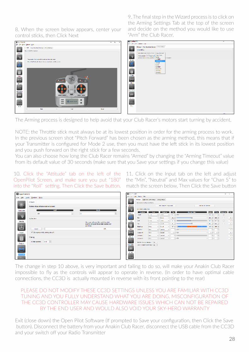
8. When the screen below appears, center your control sticks, then Click Next
9. The final step in the Wizard process is to click on the Arming Settings Tab at the top of the screen and decide on the method you would like to use “Arm” the Club Racer.
The Arming process is designed to help avoid that your Club Racer’s motors start turning by accident.
NOTE: the Throttle stick must always be at its lowest position in order for the arming process to work.In the previous screen shot “Pitch Forward” has been chosen as the arming method, this means that if your Transmitter is configured for Mode 2 use, then you must have the left stick in its lowest position and you push forward on the right stick for a few seconds.You can also choose how long the Club Racer remains “Armed” by changing the “Arming Timeout” value from its default value of 30 seconds (make sure that you Save your settings if you change this value)
28
TROUBLE SHOOTING
TESTING YOUR ANAKIN CLUB RACER ARMING PROCESS WORKSEnsure that your propellers are not yet connected to your Anakin Club Racer, Insert your Battery into thebattery bay and secure tightly with a strap. Turn on your Radio Transmitter. Make sure that your AnakinClub Racer is in a safe position with nothing close by that could be damaged when you start the motors.Connect the battery, ensure that your throttle stick is in the lowest position and then push the stick which you have configured earlier to arm your Anakin Club Racer.
If your Anakin Club Racer will not respond to your “Arming” start sequence, then you should re-connect the usb cable, restart the OpenPilot software and check that on the Configuration -> Input -> ArmingSettings screen, a valid option has been selected and click the Save button.
If you find that any motors are “twitching” or turning when you have not yet initiated your Armingsequence, this could indicate one of several things:
1. ESC has not been properly calibrated during the OpenPilot calibration process (see “Manually re-calibrating your ESCs” below)
2. Faulty motor (try replacing the motor)
3. Faulty ESC (try replacing the ESC)
4. Bad soldering connection between your motor and its ESC or ESC and PDB (resolder the connections)
5. Motor mount screws are too long and have been screwed too far into the base of your motors (use correct length screws with a new motor)
29
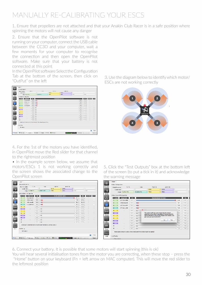
MANUALLY RE-CALIBRATING YOUR ESCS1. Ensure that propellers are not attached and that your Anakin Club Racer is in a safe position where spinning the motors will not cause any danger2. Ensure that the OpenPilot software is not running on your computer, connect the USB cable between the CC3D and your computer, wait a few moments for your computer to recognise the connection and then open the OpenPilot software. Make sure that your battery is not connected at this pointIn the OpenPilot software Select the Configuration Tab at the bottom of the screen, then click on “OutPut” on the left
4. For the 1st of the motors you have identified, in OpenPilot move the Red slider for that channel to the rightmost position• In the example screen below, we assume that motors/ESCs 1 is not working correctly and the screen shows the associated change to the OpenPilot screen
5. Click the “Test Outputs” box at the bottom left of the screen (to put a tick in it) and acknowledgethe warning message
6. Connect your battery. It is possible that some motors will start spinning (this is ok)You will hear several initialisation tones from the motor you are correcting, when these stop – press the “Home” button on your keyboard (Fn + left arrow on MAC computer). This will move the red slider to the leftmost position
3. Use the diagram below to identify which motor/ESCs are not working correctly
30
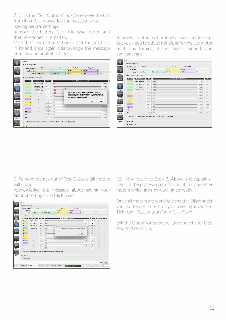
7. Click the “Test Outputs” box (to remove the tick from it) and acknowledge the message about saving neutral settings. Remove the battery, Click the Save button and then re-connect the batteryClick the “Test Outputs” box (to put the tick back in it) and once again acknowledge the message about saving neutral settings.
9. Remove the tick out of Test Outputs (all motors will stop)Acknowledge the message about saving your Neutral settings and Click Save
10. Now return to Step 3. Above and repeat all steps in the process up to this point (for any other motors which are not working correctly) Once all motors are working correctly. Disconnect your battery, Ensure that you have removed the Tick from “Test outputs” and Click Save
Exit the OpenPilot Software, Disconnect your USB lead and continue.
8. Several motors will probably now start turning, but you need to adjust the slider for the 1st motoruntil it is turning at the lowest, smooth and constant rate
31
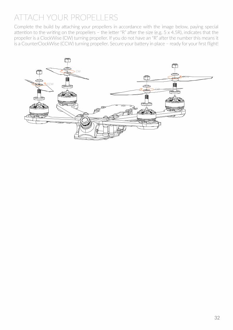
ATTACH YOUR PROPELLERS
CW
CCW
CCW
CW
Complete the build by attaching your propellers in accordance with the image below, paying special attention to the writing on the propellers – the letter “R” after the size (e.g. 5 x 4.5R), indicates that the propeller is a ClockWise (CW) turning propeller. If you do not have an “R” after the number this means it is a CounterClockWise (CCW) turning propeller. Secure your battery in place – ready for your first flight!
32
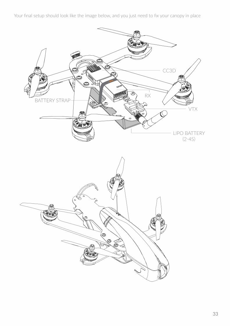
Your final setup should look like the image below, and you just need to fix your canopy in place
CC3D
BATTERY STRAP
VTX
RX
LIPO BATTERY (2-4S)
33
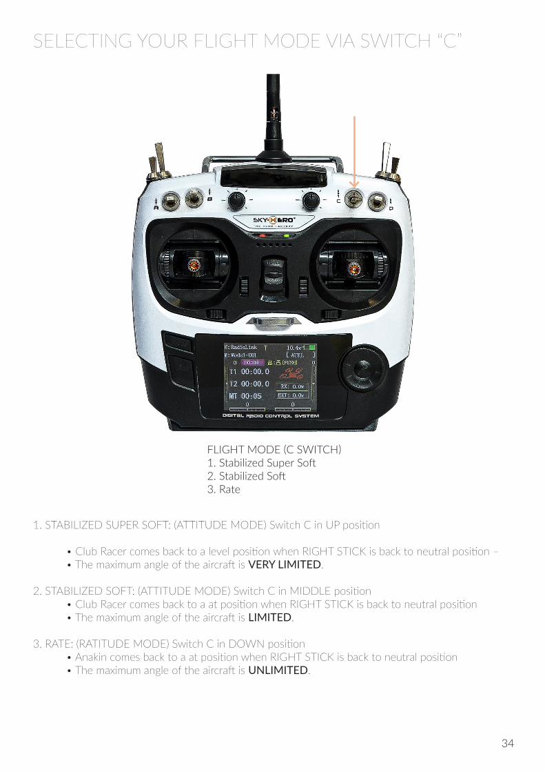
FLIGHT MODE (C SWITCH)1. Stabilized Super Soft2. Stabilized Soft3. Rate
1. STABILIZED SUPER SOFT: (ATTITUDE MODE) Switch C in UP position
• Club Racer comes back to a level position when RIGHT STICK is back to neutral position – • The maximum angle of the aircraft is VERY LIMITED.
2. STABILIZED SOFT: (ATTITUDE MODE) Switch C in MIDDLE position • Club Racer comes back to a at position when RIGHT STICK is back to neutral position • The maximum angle of the aircraft is LIMITED.
3. RATE: (RATITUDE MODE) Switch C in DOWN position • Anakin comes back to a at position when RIGHT STICK is back to neutral position • The maximum angle of the aircraft is UNLIMITED.
SELECTING YOUR FLIGHT MODE VIA SWITCH “C”
34

BEFORE YOU TAKE OFFRefer to and follow all safety precautions mentioned in the “General Instructions and Guidelines for use” section of this manual.Check that your aircraft is ready for flight with no loose screws or fittings (pay special attention to the propellers) insert a battery into the battery bay and use the provided strap to secure the battery in place.
Refer to and follow all safety precautions mentioned in the “Safety Advice” and “General Instructions and Guidelines for Use” sections of this manualMake sure that your transmitter controls are all in their correct positions and that the throttle is off. Ensure that you always turn on your transmitter before connecting the Lipo battery power. After flying make sure that once the motors have stopped turning, you always disconnect your aircraft battery before turning off your Transmitter.
MOTOR ARMING AND TAKING OFFYou arm your motors by using the sequence that you recorded during the transmitter setup stage of this manual. Make sure that the throttle control is at its lowest position and then push the other control to the Motor Arming position.To stop the motors, you should have the throttle stick at its lowest position and you push the other stick in the opposite direction to the one you used to Arm the motors
7
- Now you can see your signal power level on your Link9 radio
Signal power level: Lo id High
HOW TO CONNECT & BIND (with Sky-Hero LINK9 RX & TX)
FLIGHT MODES
1. STABILIZED SUPER SOFT: (ATTITUDE MODE) - Switch 3 in UP postionAnakin comes back to a flat position when LEFT STICK is back to neutral position - The maximal angle of the drone is VERY LIMITED.
2. STABILIZED SOFT: (ATTITUDE MODE) - Switch 3 in MIDDLE postionAnakin comes back to a flat position when LEFT STICK is back to neutral position - The maximal angle of the drone is LIMITED.
3. RATE: (RATITUDE MODE) - Switch 3 in DOWN postionAnakin comes back to a flat position when LEFT STICK is back to neutral position - The maximal angle of the drone is UNLIMITED.
Then:• Turn your Link9 on• Plug your lipo in your model• Push and hold the bind button until the Led start blinking• Push again the button again until it starts blinking blue (meaning S.BUS-mode)• Once the Led turns solid blue, it’s bound
BASIC COMMANDSSee hereunder how to control your Anakin.
Throttle: it cannot hold the central position when released.Roll: it can return to the central position when released.Pitch: it can return to the central position when releasedYaw: it can return to the central position when released.
LEFT STICK RIGHT STICK
[MODE 1]
Pitch: it can return to the central position when releasedRoll: it can return to the central position when released.Throttle: it cannot hold the central position when released.Yaw: it can return to the central position when released.
LEFT STICK RIGHT STICK
[MODE 2]
With Link9. you have to connect with the cable as shown on the picture.(Yellow cable is not used)
The notes below are for a transmitter setup as Mode 2 (for Mode 1 replace “RIGHT” with “LEFT”)
35
USING ALTERNATIVE RADIOS & RECEIVERS (not the SKY-HERO Link9)
SKY-HERO CC3D FLIGHT CONTROLLER IS ONLY COMPATIBLE WITH: • S-BUS receivers • JR & Spektrum Satellite receivers • PPM receivers
Please note that PWM (Pulse With Modulation) is NOT SUPPORTED!
During the CC3D setup process, you will be asked to choose the receiver type from four options, please choose your receiver according to the box above, (but do not choose PWM as this is not compatible with the Anakin Club Racer ESCs) if you make the wrong choice here the receiver won’t work. Click “Next”when done.
You will need to know exactly what kind of receiver you are using as different receivers require different setup steps. The Anakin Club Racer’s built-in Sky-Hero CC3D supports 3 kinds of receivers: PPM, S.BUS and DSM.
PPM (PULSE POSITION MODULATION) A PPM signal (often referred to as a PPM stream) is basically a series of PWM signals sent one after another on the same wire. So instead of continuously sending the information for 1 channel or servo, the information for all servo’s or ESCs is sent in a row on the same wire. The advantage of such a PPM signal is that only one signal wire is needed instead of all the individual wires.
For PPM receiver, the WHITE and GREY wire of the multi-coloured signal wire needs to be swapped FIRST, then connect the GREY RED BLACK plug to the PPM output of your receiver, no other wires need to be connected.
S.BUS The S.Bus is another communication protocol from Futaba that can also be used on other radios like Taranis and Radiolink. It also combines all output channel information into single servo lead. For S.Bus receiver, use the S.Bus signal wire and connect it to the S.Bus port on the main board, there is no need to connect the multicoloured PWM/PPM signal cable from its socket.
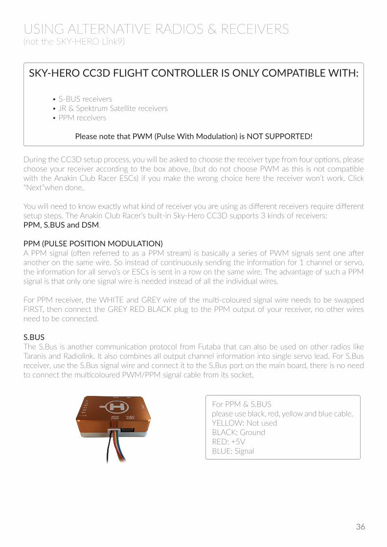
For PPM & S.BUS please use black, red, yellow and blue cable. YELLOW: Not used BLACK: Ground RED: +5V BLUE: Signal
36
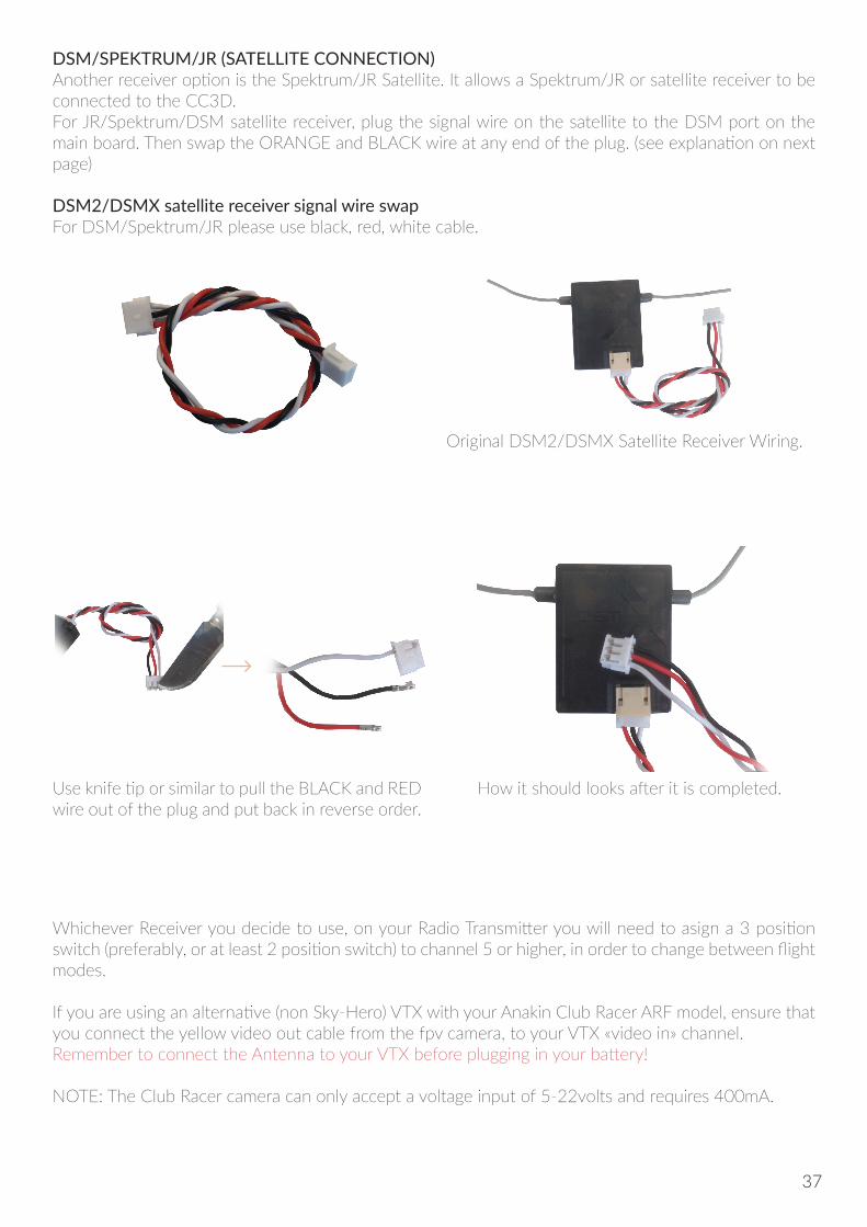
DSM/SPEKTRUM/JR (SATELLITE CONNECTION)Another receiver option is the Spektrum/JR Satellite. It allows a Spektrum/JR or satellite receiver to be connected to the CC3D.For JR/Spektrum/DSM satellite receiver, plug the signal wire on the satellite to the DSM port on the main board. Then swap the ORANGE and BLACK wire at any end of the plug. (see explanation on next page)
DSM2/DSMX satellite receiver signal wire swapFor DSM/Spektrum/JR please use black, red, white cable.
Original DSM2/DSMX Satellite Receiver Wiring.
Whichever Receiver you decide to use, on your Radio Transmitter you will need to asign a 3 position switch (preferably, or at least 2 position switch) to channel 5 or higher, in order to change between flight modes.
If you are using an alternative (non Sky-Hero) VTX with your Anakin Club Racer ARF model, ensure that you connect the yellow video out cable from the fpv camera, to your VTX «video in» channel. Remember to connect the Antenna to your VTX before plugging in your battery!
NOTE: The Club Racer camera can only accept a voltage input of 5-22volts and requires 400mA.
Use knife tip or similar to pull the BLACK and RED wire out of the plug and put back in reverse order.
How it should looks after it is completed.
37
LIMITED WARRANTYWARRANTY AND REPAIRS
Warranty requests will be processed only with an original proof of purchase from an authorized SKY-HERO dealer, showing the name of the buyer as well as the date of purchase. If the case for Warranty is confirmed, the product will be repaired. Only SKY-HERO will be able to take the decision about repairing the product. SKY-HERO will only accept a return under warranty in case of evident product failures.In case of paid repairs, we establish a quote that we will provide to you or to your dealer. The repairs will be carried out only after we have received confirmation from you or the dealer, regarding payment. The price of the repairs must be paid to the dealer. For chargeable repairs, we charge at least 30 minutes of work in the workshop as well as forwarding fees. In the absence of an agreement for the repairs within a period of 90 days, we reserve the option to destroy the product or use it otherwise.
WARRANTY PERIOD
Exclusive Warranty: SKY-HERO ensures the product purchased (the «Product») will be free from defects in improper materials and work-manship (subject to the terms set forth herein) in accordance with the official documentation for the applicable Warranty Period from the date of retail purchase. Warranty is governed by and construed under the laws of the country in which the original product purchase took place. The warranty period is 6 months and the duration of warranty obligation of 18 months at the expiration of the warranty period.
WARRANTY LIMITATIONS
(a) The Warranty applies only to the original purchaser and is not-transferable. The Purchaser’s legal rights consists of repair or exchange under this Warranty. The Warranty applies only to products purchased from an authorized dealer of SKY-HERO product or by direct sale from SKY-HERO. Sales via third parties are not covered by this Warranty. Your Anakin Club Racer is covered by this Warranty under the specified Warranty period starting from the original purchase date. Proof of the original purchase date is required for Warranty service. SKY-HERO reserves the right to modify the provisions of this Warranty without prior notice and then revokes the existing Warranty provisions.(b) SKY-HERO assumes no Warranty as to the merchantability of the product capabilities for any given use of the product. It is the sole responsibility of the Buyer to verify whether the product is suitable for its intended purpose.(c) Buyer’s rights: SKY-HERO will inspect the product and at its sole discretion, repair or replace it with a refurbished product or functional equivalent. These are the Buyer’s exclusive legal rights of recovery where a defect is found. The decision made by SKY-HERO will be final and binding.SKY-HERO may refuse to provide inspection, repair or replacement service for products that are out of Warranty and will charge fees if these services are provided for out-of-warranty products.Damage or alteration of Warranty, quality or authenticity stickers, and/or product serial or electronic numbers, unauthorized repair or modification, or any physical damage to the product or evidence of opening or tampering with the product casing will also avoid this Warranty.
ATTENTION
We only carry out and cover repairs (under valid warranty) to electronic components and engines and motors. Repairs to anything else, must therefor be carried out by the purchaser themself.
DAMAGE LIMITATION
To the extent permited by applicable law, SKY-HERO disclaims any infringement, consequential, indirect, or incidental damages, including but not limited to loss of profits, lost business investments, lost goodwill, or damages.In addition, SKY-HERO shall also not be responsible for failure of any third party equipment, even if SKY-HERO has been advised of the possibility. SKY-HERO shall not be liable for any personal injury or death or any loss or damages to property arising from the product used in a situation in which personal injury or deaths is likely occur.If you are not ready, as a buyer, to accept the liability associated with the use of the product, we ask you to return the complete product to your point of purchase, unused and in its original packaging.
38

QUESTIONS, ASSISTANCE AND REPAIRS
Without consulting SKY-HERO directly, your local dealer or point of sale can perform an estimate as to your eligibility for repair under our Warranty. Please, in such a case, contact your dealer who will agree with SKY-HERO of an appropriate decision, to assist you as soon as possible.
REPAIRS UNDER WARRANTY
If your product requires maintenance or repair, please contact either your dealer or SKY-HERO directly. Package the product carefully. Please note that the original packing carton does not, as a general rule, protect the product from damage that can occur during transport. Use a Parcel delivery service that provides tracking of shipment as well as sufficient carriage insurance, as SKY-HERO can accept no responsibility for the product until it has been received and signed for by one of our employees.Please ensure that you provide a valid proof of purchase, detailed reasons for the return as well as a list of all items included within your parcel. We also need a full return mailing address together with phone number (please provide the international dialling code as necessary) and a contact e-mail address in case of questions.
WEB AND ONLINE ORDERS WARRANTY
Warranty requests will only be processed if we are able to confirm that you purchased the item direct from SKY-HERO website and if the item is still under Warranty. Only SKY-HERO will be able to take the decision about repairing the product. SKY-HERO will only accept a return under warranty in case of evident product failures.In case of out of warranty (chargeable repairs), we provide you with a quote that you will need to accept and pay in advance. For chargeable repairs, we charge at least 30 minutes of work in the workshop as well as return shipping fees. In the absence of an agreement for the repairs within a period of 90 days, we reserve the option to destroy the product or use it otherwise, unless you agree to pay the return shipping cost.
39