analog-addressable fire alarm control panel, … · work on the motherboard. configuration manual...
TRANSCRIPT
Configuration manual
1
MANUAL FOR SYSTEM CONFIGURATION,
COMMISSIONING ANDMAINTENANCE
EN 54-2EN 54-4EN 54-21EN 12094-1
ANALOG-ADDRESSABLE FIRE ALARM CONTROL PANEL,EXTINGUISHANT SYSTEM CONTROL PANEL,ALARM TRANSMISSION AND FAULT WARNING ROUTING EQUIPMENT
00510051-CPR-14980051-CPR-1499

2 Warranty
Fire detection and extinguishant system
Warranty
INIM Electronics s.r.l. (Seller, Our, Us) warrants the original purchaser that this product shall be free from defects in
materials and workmanship under normal use for a period of 24 months. As INIM Electronics s.r.l. does not install this
product directly, and due to the possibility that it may be used with other equipment not approved by Us; INIM
Electronics s.r.l. does not warrant against loss of quality, degradation of performance of this product or actual damage
that results from the use of products, parts or other replaceable items (such as consumables) that are neither made nor
recommended by INIM Electronics. Seller obligation and liability under this warranty is expressly limited to repairing or
replacing, at Seller's option, any product not meeting the specifications. In no event shall INIM Electronics s.r.l. be liable
to the purchaser or any other person for any loss or damage whether direct of indirect or consequential or incidental,
including without limitation, any damages for lost profits, stolen goods, or claims by any other party caused by defective
products or otherwise arising from the incorrect or otherwise improper installation or use of this product.
This warranty applies only to defects in parts and workmanship relating to normal use. It does not cover:
• damage arising from improper maintenance or negligence
• damage caused by fire, flood, wind or lightning
• vandalism
• fair wear and tear
IINIM Electronics s.r.l. shall, at its option, repair or replace any defective products. Improper use, that is, use for purposes
other than those mentioned in this manual will void the warranty. Contact Our authorized dealer, or visit our website for
further information regarding this warranty.
Limited warranty
INIM Electronics s.r.l. shall not be liable to the purchaser or any other person for damage arising from improper storage,
handling or use of this product.
Installation of this Product must be carried out by qualified persons appointed by INIM Electronics. Installation of this
Product must be carried out in accordance with Our instructions in the product manual.
Copyright
The information contained in this document is the sole property of INIM Electronics s.r.l.
No part may be copied without written authorization from INIM Electronics s.r.l.
All rights reserved.

Configuration manual
Table of contents 3
Table of contents
Warranty.......................................................................................................................... 2
Limited warranty........................................................................................................... 2
Copyright........................................................................................................................ 2
Table of contents ......................................................................................................... 3
Chapter 1 General information .................................................................................................... 51.1 Manufacturer's details .....................................................................................................................5
1.2 About this manual ............................................................................................................................5
1.3 Description of the configuration and programming procedures .......................................6
1.4 Operator classification - Access Levels ......................................................................................6
Chapter 2 Configuration ................................................................................................................ 72.1 First startup......................................................................................................................................... 7
2.2 Access to programming.................................................................................................................8
2.3 Accessing the configuration menu .............................................................................................8
2.4 Access to the device modification menu..................................................................................9
2.5 Resetting factory default data .....................................................................................................10
Chapter 3 System Parameters .....................................................................................................113.1 General parameters of the control panel ................................................................................ 11
3.2 Configuring the Ethernet network............................................................................................. 11
3.3 Configuring the Hornet+ network............................................................................................. 12
3.4 Configuring the loops ................................................................................................................... 12
3.5 SD card functions........................................................................................................................... 15
3.6 Configuring the terminals ............................................................................................................ 15
3.7 Configuring the users.................................................................................................................... 15
3.8 Configuring the communicator .................................................................................................16
3.9 Configuring the extinction channel .......................................................................................... 17
3.10 Setting the date and time............................................................................................................ 20
3.11 Firmware revision ...........................................................................................................................21
Chapter 4 Parameters of devices and their groupings.........................................................224.1 Loop point parameters ................................................................................................................ 22
4.2 Parameters of control panel terminals .................................................................................... 23
4.3 Zone parameters ........................................................................................................................... 24
4.4 Output group parameters ........................................................................................................... 24
4.5 Replicate programming procedure.......................................................................................... 25
Chapter 5 Commissioning...........................................................................................................265.1 Testing the Control panel ........................................................................................................... 26
5.2 Testing to detectors and manual activations..........................................................................27
5.3 Testing signalling and activations ..............................................................................................27
5.4 Extinction system test ...................................................................................................................27
Chapter 6 Maintenance................................................................................................................286.1 Testing the control panel ............................................................................................................ 28
6.2 Testing the detectors ................................................................................................................... 28
6.3 Manual activation test .................................................................................................................. 28
6.4 Testing signalling and activations ............................................................................................. 28
6.5 Testing the extinction system.................................................................................................... 28

4 Table of contents
Fire detection and extinguishant system
Configuration manual
General information 5
Chapter 1
General information
1.1 Manufacturer's details
Manufacturer: INIM ELECTRONICS s.r.l
Production plant: Centobuchi, via Dei Lavoratori 10
Comune: 63076, Monteprandone (AP), Italy
Tel.: +39 0735 705007
Fax: +39 0735 704912
E-mail: [email protected]
Web: www.inim.biz
The persons authorized by the manufacturer to repair or replace the parts of this system, hold authorization to work onINIM Electronics brand devices only.
1.2 About this manual
Manual code: DCMCINE0PREVIDIAC
Version: 1.00
This manual describes the procedures for the configuration, commissioning and maintenance of the Previdia Compactfire-detection system.
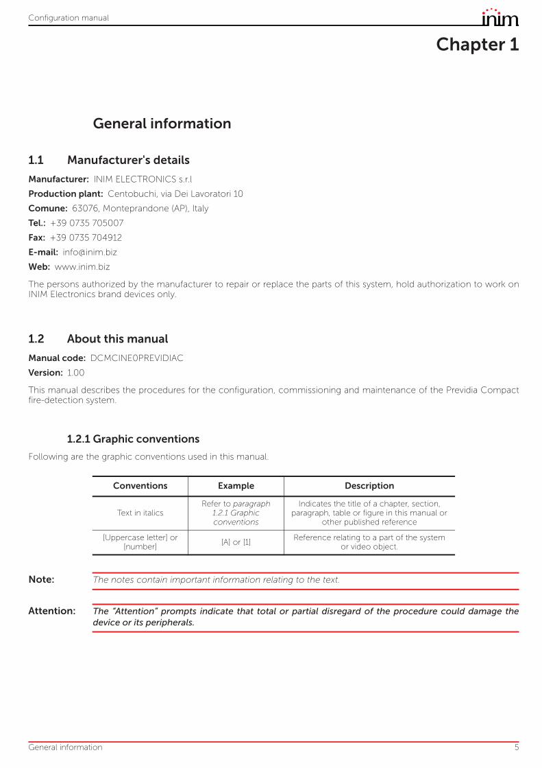
1.2.1 Graphic conventions
Following are the graphic conventions used in this manual.
Note: The notes contain important information relating to the text.
Attention: The “Attention” prompts indicate that total or partial disregard of the procedure could damage thedevice or its peripherals.
Conventions Example Description
Text in italicsRefer to paragraph
1.2.1 Graphic conventions
Indicates the title of a chapter, section, paragraph, table or figure in this manual or
other published reference
[Uppercase letter] or [number]
[A] or [1]Reference relating to a part of the system
or video object.

6 General information
Fire detection and extinguishant system
1.3 Description of the configuration and programming procedures
Following is a flow chart which summarizes the operations to be carried out during the installation and commissioningphases of the Previdia Compact system and indications regarding the manuals to refer to for each operation.
1. Installation and cabling (refer to the Installation Manual)
2. Addressing devices
3. Initializing (refer to the Installation Manual)
4. Configuration from the front plate (operations described in this manual)
5. Troubleshooting (operations described in this manual)
6. Connection to PC and reading (optional)
7. Configuration of parameters (editing data, optional)
8. Writing on control panel and testing (optional)
9. Commissioning (operations described in this manual)
10. System handover
11. Maintenance (operations described in this manual)
1.4 Operator classification - Access Levels
The control panel has 4 distinct access levels:
Level 1: Public level - this is the normal access level of the control panel and is the access level for building inhabitantswho are neither authorized to use the system nor instructed in its use.
This level allows building inhabitants to view information on the screen and signalling LEDs, interact with the system (inaccordance with Level 1) and scroll through the information by means of the buttons and touchscreen. Level 1 allows thefollowing operations only:
• mute buzzer
• test signalling LEDs
• activate alarm signalling when an early-warning process is running
Level 2: Authorized users - this access level is for the system supervisors and is for authorized personnel who areadequately instructed in the use of the system and its functions.
Access requires the use of a key or entry of a valid access code with sufficient access rights. In addition to the operationsdescribed for level 1 it is also possible to carry out the following operations:
• mute alarm signalling devices
• rearm the control panel
• activate alarm signalling devices manually
• disable control panel elements
• place in test status one or more of the system elements
Level 3: Programming - this access level is for specialized technical operators who carry out system configuration,commissioning and maintenance.
Access requires entry of a valid access code with sufficient access rights after inserting a jumper which enablesprogramming. Refer to the manual for system configuration, commissioning and maintenance.
ONLY authorized technicians, appointed by the Manufacturer can, by means of special tools, carry out repair work onthe motherboard.
Level 4: ONLY authorized technicians, appointed by the Manufacturer can, by means of special tools, carry out repairwork on the motherboard.
Configuration manual
Configuration 7
Chapter 2
Configuration
2.1 First startup
Once the installation and cabling procedures have been completed (refer to the Installation Manual of the PrevidiaCompact system) the system is ready for first startup.
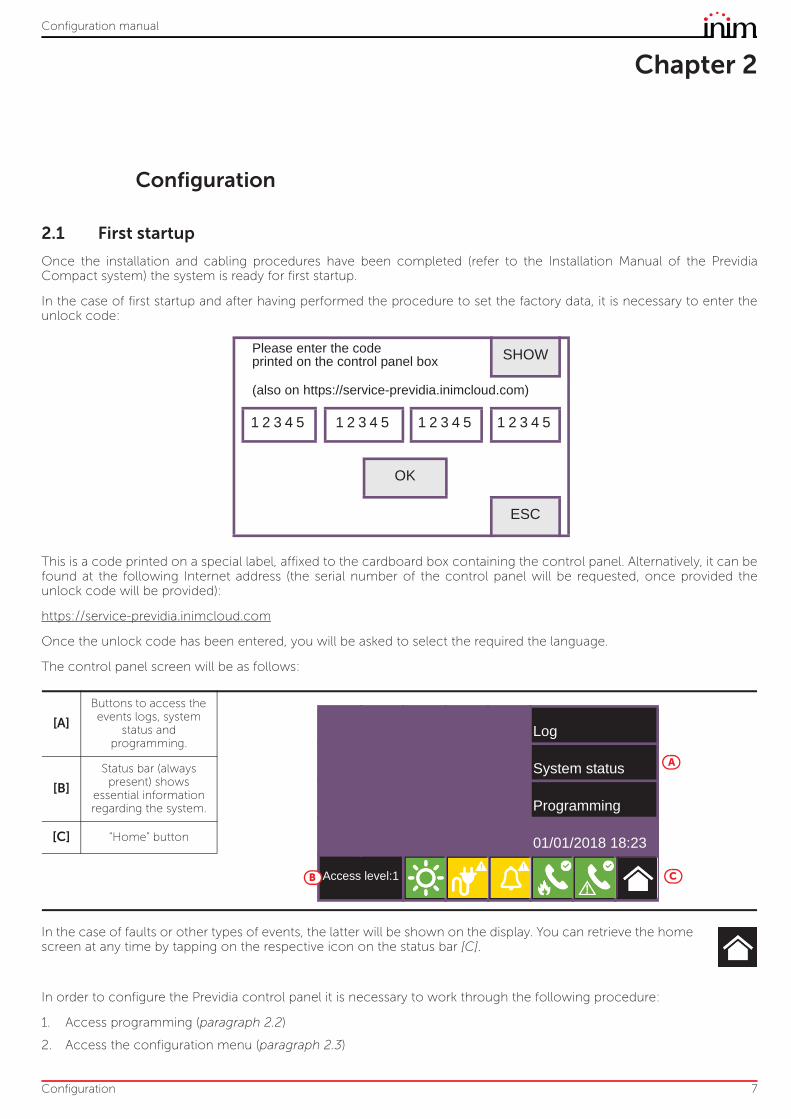
In the case of first startup and after having performed the procedure to set the factory data, it is necessary to enter theunlock code:
This is a code printed on a special label, affixed to the cardboard box containing the control panel. Alternatively, it can befound at the following Internet address (the serial number of the control panel will be requested, once provided theunlock code will be provided):
https://service-previdia.inimcloud.com
Once the unlock code has been entered, you will be asked to select the required the language.
The control panel screen will be as follows:
In the case of faults or other types of events, the latter will be shown on the display. You can retrieve the homescreen at any time by tapping on the respective icon on the status bar [C].
In order to configure the Previdia control panel it is necessary to work through the following procedure:
1. Access programming (paragraph 2.2)
2. Access the configuration menu (paragraph 2.3)
[A]
Buttons to access the events logs, system
status and programming.
[B]
Status bar (always present) shows
essential information regarding the system.
[C] “Home” button
Please enter the codeprinted on the control panel box SHOW
(also on https://service-previdia.inimcloud.com)
1 2 3 4 5 1 2 3 4 5 1 2 3 4 5 1 2 3 4 5
OK
ESC
Log
System status
Programming
01/01/2018 18:23
Access level:1 C
A
B
8 Configuration
Fire detection and extinguishant system
3. Enroll the loop devices, after the respective fault search (paragraph 3.4.2)
4. Set up the control panel parameters (Chapter 3, System Parameters)
5. Configure the connected devices and their groups (Chapter 4, Parameters of devices and their groupings)
6. Check eventual signalling and search for faults (paragraph 5.3)
7. Set the date and time (paragraph 3.10)
Note: Once the configuration operations have been completed correctly, the control panel will be ready tooperate.The control panel is configured to consider each input point (detector, module, terminal) as a fire-alarmpoint. Therefore, in the event of a fire alarm it will activate all the outputs available on its loops orterminals.At this point it is necessary to proceed with eventual changes to the configuration data for thedistribution of points in zones, edit descriptions of the various system elements, define specificactivation sequences, etc.
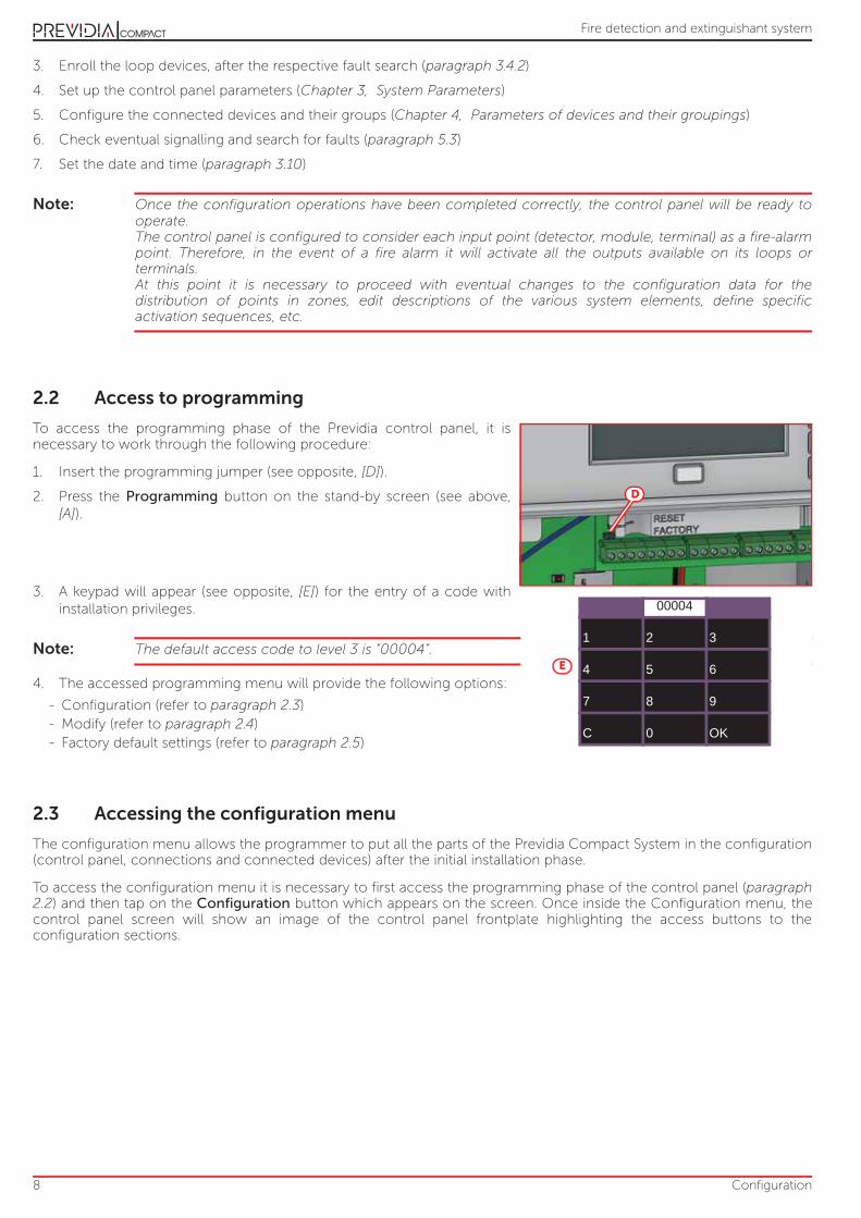
2.2 Access to programming
To access the programming phase of the Previdia control panel, it isnecessary to work through the following procedure:
1. Insert the programming jumper (see opposite, [D]).
2. Press the Programming button on the stand-by screen (see above,
[A]).
3. A keypad will appear (see opposite, [E]) for the entry of a code with
installation privileges.
Note: The default access code to level 3 is “00004”.
4. The accessed programming menu will provide the following options:
- Configuration (refer to paragraph 2.3)
- Modify (refer to paragraph 2.4)
- Factory default settings (refer to paragraph 2.5)
2.3 Accessing the configuration menu
The configuration menu allows the programmer to put all the parts of the Previdia Compact System in the configuration(control panel, connections and connected devices) after the initial installation phase.
To access the configuration menu it is necessary to first access the programming phase of the control panel (paragraph2.2) and then tap on the Configuration button which appears on the screen. Once inside the Configuration menu, thecontrol panel screen will show an image of the control panel frontplate highlighting the access buttons to theconfiguration sections.
D
00004
1 2 3
4 5 6
7 8 9
C 0 OK
E
Configuration manual
Configuration 9
2.4 Access to the device modification menu
Once the Previdia Compact system has been configured it is necessary to set the parameters, or change the defaultprogramming of the devices connected to the control panel (single or in group).
The Previdia Compact control panel provides a direct programming option on the control panel for its connecteddevices and their logical groups (zones and output groups) without need of accessing the “Configuration” section(paragraph 2.3). To access it, you must access the programming phase of the control panel (paragraph 2.2) and thenpress the Modify button on the menu on the screen.
The section you access will show Ia list containing the access buttons to the programming subsections::
• Zones (refer to paragraph 4.3)
• Output groups (refer to paragraph 4.4)
• I/O Lines (refer to paragraph 4.2)
• Loop points (refer to paragraph 4.1)
Pressing one of these buttons will allow you to view the list of the respective elements. The list shows the index,description, and status of each element, and by tapping on one of the lines, you will be able to program the parametersof the individual element.
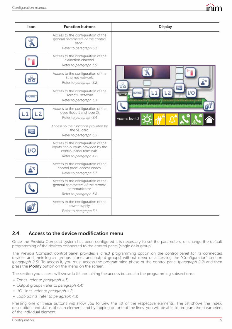
Icon Function buttons Display
Access to the configuration of the general parameters of the control
panel.
Refer to paragraph 3.1
Access to the configuration of the extinction channel.
Refer to paragraph 3.9
Access to the configuration of the Ethernet network.
Refer to paragraph 3.2
Access to the configuration of the Hornet+ network.
Refer to paragraph 3.3
Access to the configuration of the loops (loop 1 and loop 2).
Refer to paragraph 3.4
Access to the functions provided by the SD card.
Refer to paragraph 3.5
Access to the configuration of the inputs and outputs provided by the
control panel terminals.
Refer to paragraph 4.2
Access to the configuration of the control panel access codes.
Refer to paragraph 3.7
Access to the configuration of the general parameters of the remote
communicator.
Refer to paragraph 3.8
Access to the configuration of the power supply.
Refer to paragraph 5.1
Access level:3

10 Configuration
Fire detection and extinguishant system
2.5 Resetting factory default data
The resetting of the factory default data and consequent deletion of theconfiguration data on the Previdia Compact control panel can be done intwo ways:
• Selecting the Factory data option from the programming menu (refer to paragraph 2.2).
• Using the buttons available on the plastic support of the electronic boards, as shown in the figure [A]:
1. Press the FACTORY button.
2. While holding down the FACTORY, button, press the RESET button
then release it.
After confirmation of the request for reset to factory default data, the control panel will carry out the same operations asat first startup, described at the beginning of this manual.
A progress bar will confirm factory data resetting in course.
A

Configuration manual
System Parameters 11
Chapter 3
System Parameters
The configuration of the Previdia Compact control panel, its interfaces and external connections provides for the settingsof a series of parameters reachable from the control panel by accessing control panel programming (paragraph 2.2) andthen pressing the Configuration button on the menu shown on the screen.
Once inside the Configuration menu (paragraph 2.3), the control panel screen will show an image of the control panelfrontplate highlighting the access buttons to the configuration sections.
3.1 General parameters of the control panel
Tapping on the appropriate icon inside the control panel configuration screen accesses the configurationsection of some of the control panel parameters.
The available parameters are:
• Panel name, editable field for the description of the control panel
• Mains failure delay, field for the delay (expressed in minutes) which must pass between detection of mains failure by the control panel and mains failure signalling
• Disable buzzer, option that, if activated, disables the control panel buzzer
• Direct alarm on second prealarm, option that, if activated, generates an alarm signal as soon as two detectors go into prealarm status, regardless of the zone they belong to. Otherwise the alarm condition will activate at the end of the first prealarm time.
The Esc and Set buttons will allow you to exit the sectionwithout changing the programming or saving it.
3.2 Configuring the Ethernet network
If an Ethernet network connection is used, it will be necessary to set up the IP address and parameters of the network.
This operation must be carried out for each of the Previdia control panels and repeaters connected to the Ethernetnetwork via LAN cable.
To set the network parameters you must enter the programming phase of the control panel (paragraph 2.2)and then tap on the appropriate icon inside the control panel configuration screen.
The available parameters are:
• IP address
• Netmask
• Gateway
• Port
The Esc and Set buttons will allow you to exit the sectionwithout changing the programming or saving it.
Previdia Compact Panel name
060 Mains failure delay (min)
Disable buzzer Esc
Direct alarm on second prealarm Set
Access level:3
IP 192 168 1 121
Net mask 255 255 255 0
Gateway 192 168 1 1
Port 6001 Esc Set
Access level:3
12 System Parameters
Fire detection and extinguishant system
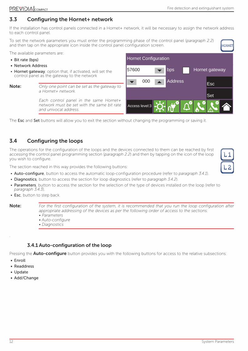
3.3 Configuring the Hornet+ network
If the installation has control panels connected in a Hornet+ network, it will be necessary to assign the network addressto each control panel.
To set the network parameters you must enter the programming phase of the control panel (paragraph 2.2)and then tap on the appropriate icon inside the control panel configuration screen.
The available parameters are:
• Bit rate (bps)
• Network Address
• Hornet gateway, option that, if activated, will set the control panel as the gateway to the network
Note: Only one point can be set as the gateway toa Hornet+ network.
Each control panel in the same Hornet+network must be set with the same bit rateand univocal address.
The Esc and Set buttons will allow you to exit the section without changing the programming or saving it.
3.4 Configuring the loops
The operations for the configuration of the loops and the devices connected to them can be reached by firstaccessing the control panel programming section (paragraph 2.2) and then by tapping on the icon of the loopyou wish to configure.
The section reached in this way provides the following buttons:
• Auto-configure, button to access the automatic loop-configuration procedure (refer to paragraph 3.4.1).
• Diagnostics, button to access the section for loop diagnostics (refer to paragraph 3.4.2).
• Parameters, button to access the section for the selection of the type of devices installed on the loop (refer to paragraph 3.4.3).
• Esc, button to step back.
Note: For the first configuration of the system, it is recommended that you run the loop configuration afterappropriate addressing of the devices as per the following order of access to the sections:• Parameters• Auto-configure• Diagnostics
.
3.4.1 Auto-configuration of the loop
Pressing the Auto-configure button provides you with the following buttons for access to the relative subsections:
• Enroll
• Readdress
• Update
• Add/Change
Hornet Configuration
57600 bps Hornet gateway
000 Address Esc
Set
Access level:3
Configuration manual
System Parameters 13
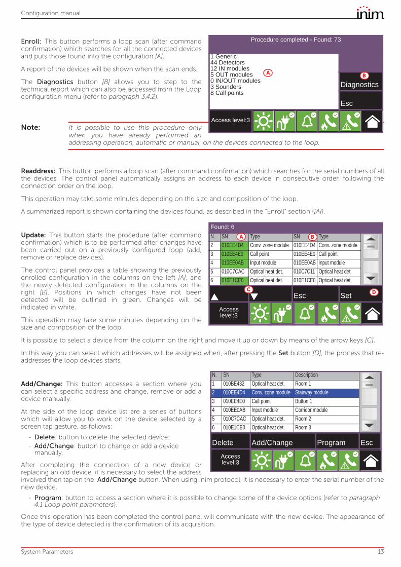
Enroll: This button performs a loop scan (after commandconfirmation) which searches for all the connected devicesand puts those found into the configuration [A].
A report of the devices will be shown when the scan ends.
The Diagnostics button [B] allows you to step to thetechnical report which can also be accessed from the Loopconfiguration menu (refer to paragraph 3.4.2).
Note: It is possible to use this procedure onlywhen you have already performed anaddressing operation, automatic or manual, on the devices connected to the loop.
Readdress: This button performs a loop scan (after command confirmation) which searches for the serial numbers of allthe devices. The control panel automatically assigns an address to each device in consecutive order, following theconnection order on the loop.
This operation may take some minutes depending on the size and composition of the loop.
A summarized report is shown containing the devices found, as described in the “Enroll” section ([A]).
Update: This button starts the procedure (after commandconfirmation) which is to be performed after changes havebeen carried out on a previously configured loop (add,remove or replace devices).
The control panel provides a table showing the previouslyenrolled configuration in the columns on the left [A], andthe newly detected configuration in the columns on theright [B]. Positions in which changes have not beendetected will be outlined in green. Changes will beindicated in white.
This operation may take some minutes depending on thesize and composition of the loop.
It is possible to select a device from the column on the right and move it up or down by means of the arrow keys [C].
In this way you can select which addresses will be assigned when, after pressing the Set button [D], the process that re-addresses the loop devices starts.
Add/Change: This button accesses a section where youcan select a specific address and change, remove or add adevice manually.
At the side of the loop device list are a series of buttonswhich will allow you to work on the device selected by ascreen tap gesture, as follows:
- Delete: button to delete the selected device.
- Add/Change: button to change or add a device manually.
After completing the connection of a new device orreplacing an old device, it is necessary to select the addressinvolved then tap on the Add/Change button. When using Inim protocol, it is necessary to enter the serial number of thenew device.
- Program: button to access a section where it is possible to change some of the device options (refer to paragraph 4.1 Loop point parameters).
Once this operation has been completed the control panel will communicate with the new device. The appearance ofthe type of device detected is the confirmation of its acquisition.
Procedure completed - Found: 73
1 Generic44 Detectors12 IN modules5 OUT modules0 IN/OUT modules3 Sounders8 Call points
Diagnostics
Esc
Access level:3
A B
Found: 6N. SN Type SN Type2 010EE4D4 Conv. zone module 010EE4D4 Conv. zone module3 010EE4E0 Call point 010EE4E0 Call point4 010EE0AB Input module 010EE0AB Input module5 010C7CAC Optical heat det. 010C7C11 Optical heat det.6 010E1CE0 Optical heat det. 010E1CE0 Optical heat det.
Esc Set
Access level:3
A B
C D
N. SN Type Description1 010BE432 Optical heat det. Room 12 010EE4D4 Conv. zone module Stairway module3 010EE4E0 Call point Button 14 010EE0AB Input module Corridor module5 010C7CAC Optical heat det. Room 26 010E1CE0 Optical heat det. Room 3
Delete Add/Change Program Esc
Access level:3

14 System Parameters
Fire detection and extinguishant system
3.4.2 Loop diagnostics
The Diagnostics button in the Loop configuration menu accesses the section for the loop diagnosis.
The upper left side of the template [A] shows some of theelectrical data of the loop.
• Loop status: indicates whether the loop is a closed ring circuit or open
• Loop O Terminal: indicates eventual short-circuits or anomalies immediately on the loop output terminals
• Loop I Terminal: indicates eventual short-circuits or anomalies immediately on the loop input terminals
• Loop Consumption: indicates the voltage draw of the loop
• Cable resistance: indicates the resistance value of the cable
The upper right side of the template [B] shows the numberand type of devices currently in configuration.
The lower part [C] provides the following buttons:
• Loop reset, button to reset the loop and reassess its status.In the event of a “Loop open” fault, it will be necessary to tap on this button in order to check whether or not the interruption has been cleared.
• Scan, button to start a scan on an already enrolled loop.The procedure verifies whether there are any connected devices which are not in the configuration, if devices have been lost or if there are any other anomalies. The results of the scan can be viewed in the section on the top right of the display.
• Show topology, button which steps to the layout screen of the devices in the configuration of the already enrolled loop.
The layout shows all the devices which are connected tothe loop and how they are connected to one another.
Any devices in alarm or fault status will be outlined in red oryellow [D].
The selection of a device accesses the management pageof the device itself
The Update button [E] refreshes the screen by updating anyalarms and faults signalled by the devices shown (restoredfault events will not be shown).
3.4.3 Loop Parameters
The Parameters button on the loop configuration menu allows you toset:
• Device protocol
• Wiring type (2 or 4 wires)
Note: If you are making a two-wire connection, you can installa maximum of 32 fire-alarm devices on the loop(detectors or call points).
Loopx: loop yyyLoop status: closedLoop O terminal: OKLoop I terminal:Loop consumption (mA): 15Cable resistance (Ohm): 0
Generic: 1Detectors: 44IN Modules: 12OUT Modules: 5IN/OUT Modules: 0Sounder/flashers: 3Call points: 8
Rearm Scan Show layout Esc
Access level:3
A B
C
Update Esc
Access level:3
001 002 003 004 005 006 007 008
D 013 014 015 016 017
E
023 024 025 D
Inim
4 wires Esc
Set
Configuration manual
System Parameters 15
3.5 SD card functions
Tapping on the appropriate icon inside the control panel configuration template accesses some of thefunctions available on the SD card.
A list with the following buttons will appear:
• Save Program Data, saves the control panel programming data to the SD card in a .dat file, the name of which coincides with the serial number of the control panel.
• Save Log, saves the contents of the events log to the SD card in a file named “xxxx_log. txt”, where “xxxx” is the serial number of the control panel.It is possible to import the data contained in the file into a spreadsheet (the character used as the delimiter of the various fields is the full stop and comma “;”).
• Read Program Data, if there is a .dat file on the SD card whose name coincides with the serial number of the control panel, the programming data contained in it will overwrite that currently used.
• Read Display Config. if the “Desktop.Bin” file is on the SD card, the data contained in it (images, buttons and labels to be displayed in the stand-by screen) will overwrite that currently used. If the previously-mentioned file is not present on the SD card, and there is the file “Logo. bmp” file is, the image contained in it (260x222 pixel) will be shown on the stand-by screen.
The Esc and Set buttons will allow you to exit the section without changing the programming or saving it.
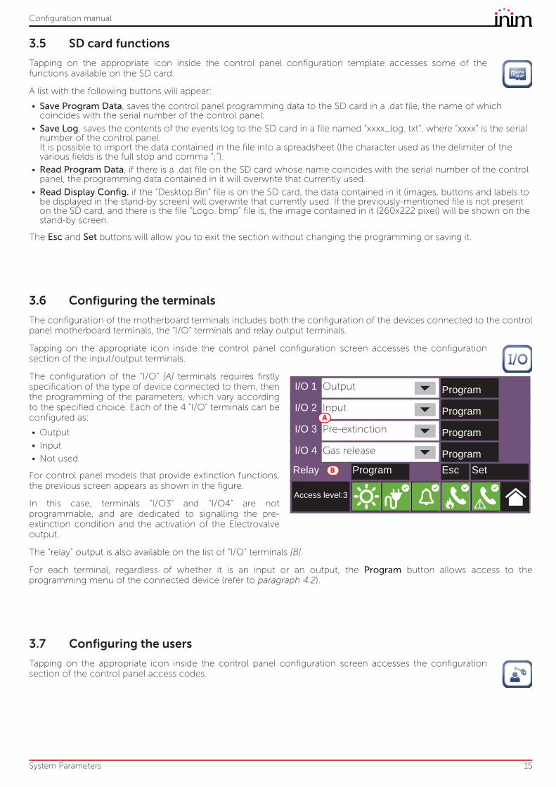
3.6 Configuring the terminals
The configuration of the motherboard terminals includes both the configuration of the devices connected to the controlpanel motherboard terminals, the “I/O” terminals and relay output terminals.
Tapping on the appropriate icon inside the control panel configuration screen accesses the configurationsection of the input/output terminals.
The configuration of the “I/O” [A] terminals requires firstlyspecification of the type of device connected to them, thenthe programming of the parameters, which vary accordingto the specified choice. Each of the 4 “I/O” terminals can beconfigured as:
• Output
• Input
• Not used
For control panel models that provide extinction functions,the previous screen appears as shown in the figure.
In this case, terminals “I/O3” and “I/O4” are notprogrammable, and are dedicated to signalling the pre-extinction condition and the activation of the Electrovalveoutput.
The “relay” output is also available on the list of “I/O” terminals [B].
For each terminal, regardless of whether it is an input or an output, the Program button allows access to theprogramming menu of the connected device (refer to paragraph 4.2).
3.7 Configuring the users
Tapping on the appropriate icon inside the control panel configuration screen accesses the configurationsection of the control panel access codes.
I/O 1 Output Program
I/O 2 Input Program
I/O 3 Pre-extinction Program
I/O 4 Gas release ProgramRelay Program Esc Set
Access level:3
A
B

16 System Parameters
Fire detection and extinguishant system
This section provides the list of available codes.
Once a code is selected, you can remove it from thesystem by pressing the Delete button.
Instead the Program button will allow you to set itsparameters:
• Description, label that identifies the user and that is shown in the events it is involved in.
• PIN, 5-figure number that identifies the user, thus allowing access to the system.
• Type, determines the set of operations the user can control. The following values are possible (refer to paragraph 1.4 Operator classification - Access Levels and the User manual):
- No code, code not enabled to access the system.
- User level, coincides with “Level 2” (authorized user)
- Superuser level, same as the previous level, with the added possibility of loop-device replacement.
- Maintenance operator level, same as the previous level with the added possibility of stopping the valve pulse for those models that support extinction functions
- User level, coincides with “Level 3” (authorized user)
Previdia Compact control panels are supplied at default withthe first 4 codes already pre-set:
3.8 Configuring the communicator
To set the network parameters you must first enter the control panel programming phase (paragraph 2.2) andthen tap on the appropriate icon inside the control panel configuration screen.
The boxes marked [A] will allow you to select thecommunication channels you want to use:
• Ethernet, for transmission of events with the SIA-IP protocol over Ethernet cable
• PREVIDIA-C-DIAL, for transmission through the optional communicator of the Previdia Compact.If selected, the following channels will also become available:
• SIM (SIA-IP), for transmission of events with the SIA-IP protocol over 3G
• SIM (Voice/SMS), for transmission of events with Contact-ID protocol, of voice messages or SMS texts over 3G
• PSTN, transmission of events with Contact-ID protocol or voice messages over the landline
The APN button [B] provides access to a section for the parameters required for the connection to the mobile network.
The Contacts button [C] accesses the phone book programming phase.
After selecting a contact, you will be able to configure it by pressing the Program button.
Code number Code type Default PIN
1 User level 00001
2 Superuser level 00002
3 Maintenance level 00003
4 Installer level 00004
5 ... No code /
N. Type Description1 User level Code 12 Superuser level Code 23 Maintenance level Code 34 Installer level Code 45 No code Code 56 No code Code 6
Delete Program Esc
Access level:3
Code parameters
Code 2 Description
PIN Esc
User level Type Set
Access level:3
PREVIDIA-C-DIAL Ethernet
SIM (SIA-IP) APN
SIM (voice/SMS) Contacts Esc
PSTN Actions Set
Access level:3
A
B
C
D
Configuration manual
System Parameters 17
If you are configuring an “SMS” or “PSTN” type channel, the communication protocol will be requested:
• SIA-IP
• Contact ID
• Voice call
• SMS
The parameters made available in the contact programming section that follows vary according to the selected protocol.
Pressing the Actions button [D] on the communicator configuration screen will access the list of communicationoperations set on the control panel. Selecting one of them and then pressing the Program button accesses theconfiguration screen.
The “Type” parameter allows you to specify which events will trigger the action (alarm, fault, etc.).
Note: For the first two actions (alarm and system failure), the “Description” and “Type” fields are not editable.
The Associated contacts button accesses a screen that allows you to specify to which contacts the eventcommunication will be sent.
If the presence of the Previdia-C-DIAL communicator, set by means of the previously-mentioned option, isdifferent from the one the control panel detects, the appropriate icon inside the control panel configurationscreen will change status and appear in yellow.
3.9 Configuring the extinction channel
The parameters of the extinction channel, for control- panels that provide one, can be accessed through thecontrol-panel programming section (paragraph 2.2), by simply tapping on the relevant icon on theconfiguration screen.
The successive sections provide the various programmable parameters (refer to the extinction flowchart and the table ofextinction-terminal functions in the installation manual).
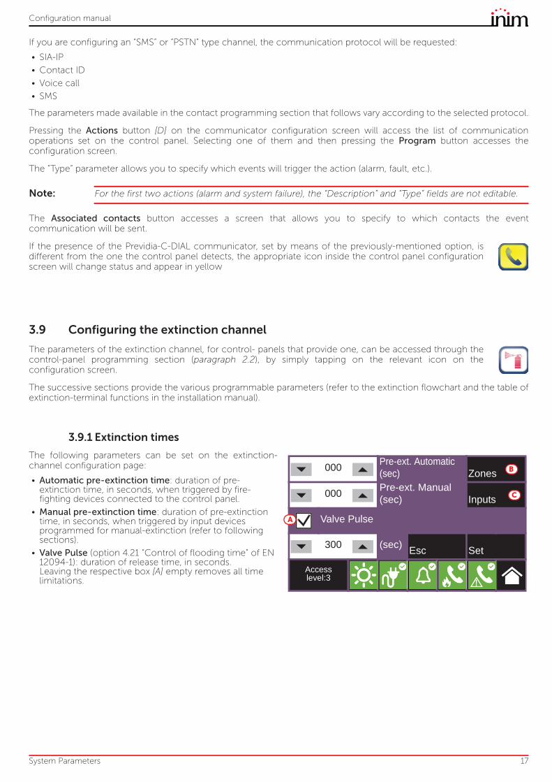
3.9.1 Extinction times
The following parameters can be set on the extinction-channel configuration page:
• Automatic pre-extinction time: duration of pre-extinction time, in seconds, when triggered by fire-fighting devices connected to the control panel.
• Manual pre-extinction time: duration of pre-extinction time, in seconds, when triggered by input devices programmed for manual-extinction (refer to following sections).
• Valve Pulse (option 4.21 “Control of flooding time” of EN 12094-1): duration of release time, in seconds.Leaving the respective box [A] empty removes all time limitations.
000 Pre-ext. Automatic (sec) Zones
000 Pre-ext. Manual (sec) Inputs
Valve Pulse
300 (sec) Esc Set
Access level:3
A
B
C

18 System Parameters
Fire detection and extinguishant system
3.9.2 Trigger zones
The Zones button [B] accesses a screen that permits up tothree zones to activate the extinction phase when, withinone of the indicated zones, a certain number of alarms isreached.
In order to select the zones, you must first activate one ofthe three available options via the [D] check box, then tapon the respective field at the side [E] to access the list ofconfigured zones. The arrow buttons [F] will allow you tospecify the number of alarms (maximum 3).
The image at the side shows how the system can beconfigured so that the extinction channel is activated whenthere are at least two alarms in zone 2.
3.9.3 Extinction input
The Inputs button [C] will allow you to configure the control-panel input points to activate the extinction functions.
EN12094-1: To ensure compliance with EN 12094-1, the inputs in use must be on-board I/O or supervised inputs onloop modules (such as the EM312SR module).It is not possible to connect more than 32 devices to each of the selected input terminals.It is necessary to specify the input associated with the “Manual Extinction” function (the others areoptional).
These functions are grouped into the following categories:
• Activate
This section provides the extinction-activation parameters.
The parameters of the “Manual extinction” command allowfor the selection of an associated group (loop 1, loop 2 orone of the “I/O” terminals [G]), and the point [H] thatactivates the release of the fire extinguishing agent inaccordance with the programmed pre-extinction time.
Selecting “--” for the group disables manual extinction onthe control panel.
• Deactivate
This section provides the parameters for stopping theextinction procedure. There are 4 different modes availablefor stopping the extinction procedure, each one attributableto a different input:
- Stop Extinct. ABORT (Option 4.27 “Emergency interruption device” of EN 12094-1): stops the extinction procedure definitively
- Stop Extinct. HOLD (Option 4.20 “Emergency hold device” of EN 12094-1): stops the extinction procedure until reset (which restarts the pre-extinction time)
- Stop Extinct. ADD (Option 4.20 “Emergency hold device” of EN 12094-1): stop the extinction procedure until reset (the pre-extinction time-counter will not be altered)
- Stop Extinct. EXTERN (Option 4.19 "Monitoring the status of components" of EN 12094-1): same as “Stop Extinc. Hold”, but activated without human intervention (for example by a door contact that inhibits the release of gas)
The parameters of the 4 commands allow for the assignment of a group (loop 1, loop 2 or one of the terminals “I/O” [G]))and the point [H] which activates the relative stop-extinction mode.
Selecting “--” for the assigned group disables the related stop-extinction mode.
EN12094-1: If the “Stop Extinction ABORT” function is utilized with a Previdia Compact control panel, the “StopExtinction HOLD” and “Stop Extinction ADD” functions cannot be associated with inputs, and vice versa.
Trigger zones Requested Alarms
Zone 2 2
1
1
Esc Set
Access level:3
D E F
Manual extinction L 1 Button 1
Esc Set
Access level:3
G H
Stop Extinct. ABORT L 1 Input module 1
Stop Extinct. HOLD L 1 Button 2
Stop Extinct. ADD L 2 Input module 2
Stop Extinct. EXTERN --
Esc Set
Access level:3
G H

Configuration manual
System Parameters 19
• Disable
This section provides the parameters of disabling theextinction procedure. There are 3 different modes availablefor disabling the extinction procedure, each one attributableto a different input:
- Disab. Extinguishing: disables all the extinction functions
- Disab. Man. Exting.: disables the programmed inputs for manual activation of the extinction procedure
- Disab. Aut. Exting. (option 4.23 “Manual only mode” of EN 12094-1): disables the automatic-activation of the extinction procedure
The parameters of the 3 different disablement modes allow for the assignment of a group (loop 1, loop 2 or one of theterminals “I/O” [G])) and the point [H] which activates the related extinction-disablement mode.
Selecting “--” for the assigned group disables the related extinction-disablement mode.
• Flow/Pressure
This section provides the parameters for the functions ofthe “Pressure switch”, “Pressure switch confirm” and “Flowswitch” that can be associated with three different inputs:
- Pressure switch (option 4.19 “Monitoring of the status of components” of EN 12094-1): input for the connection of a pressure valve that activates in the event of low pressure in the cylinders
- Flow switch (option 4.18 “Signal representing the flow of the extinguishing agent” EN 12094-1): input for the connection of a flow sensor, the activation of which signals the release of the fire-extinguishing gas
- Press. switch Confirm: input for the connection of a device used to verify the release condition of the fire-extinguishing gas by means of the pressure switch
The parameters of the 3 different functions allow for the assignment of a group (loop 1, loop 2 or one of the terminals “I/O” [G])) and the point [H] associated with the extinction function.
Selecting “--” for the assigned group disables the related function type.
3.9.4Extinction outputs
In order to configure an output for the extinction function, you must associate it with one of the default groups preparedfor this purpose, and described below.
EN12094-1: You must use on-board I/O or supervised outputs on the loop (such as the EM312SR module or sounder/flashers on the loop).
You must provide outputs associated with the following functions (the others are optional):-Electrovalve-Pre-extinction-Release
The “Electrovalve” function can only be associated with the output corresponding to the “I/O 4” terminal on themotherboard of the control panel.
The default “Pre-Extinction” function is associated with the output corresponding to the “I/O 3” terminal on themotherboard of the control panel.
Disab. Extinguishing L 1 Input module 4
Disab. Man. Exting. L 2 Button 3
Disab. Aut. Exting. --
Esc Set
Access level:3
G H
Pressure switch L 1 Button 4
Flow switch L 2 Button 5
Press. switch Confirm --
Esc Set
Access level:3
G H

20 System Parameters
Fire detection and extinguishant system
The Previdia Compact control panel has pre-configured default output groups with specific extinction functions:
EN12094-1: The previous groups can be associated with supervised outputs connected to other devices, internal orexternal to the fire extinguishing system, thus creating options 4.24 “Triggering signals to equipmentwithin the system” and 4.26 “Triggering of the equipment outside the system” of standard EN 12094-1.
3.10 Setting the date and time
Proceed with the time and date setting by selecting the timeand date pane in the lower-right corner of the start page [B]and, after entering an access code, set the individual fieldsusing the scroll arrows.
Outputs group Activation EN 12094-1Associated extinction function
3 Extinguishing Group that activates the release of the gas. Release
4Pre-
Extinguishing
Group that goes into prealarm status during the pre-extinction time and into alarm status during
the release phase.
By programming a different tone pattern (or sound) for the prealarm and alarm conditions of an output associated with
this group, this output will implement option 4.30
(“Activation of alarm devices with different signals ”).
Pre-Extinguishing
5Automatic
Exting.
Group that activates during pre-extinction and
release conditions, if they are triggered by
automatic activations (e.g. two alarms in a
specific zone).
6 Manual Exting.
Group that activates during pre-extinction and
release conditions, if they are triggered by
inputs programmed for manual extinction
activation.
7 Manual StopGroup that follows the activation of inputs
programmed as “Stop extinction Abort”, “Stop
extinction Hold” or “Stop extinction Add”.
Options 4.27 “Emergency
abort device" and 4.20
"Emergency hold device”
8 Stop By DeviceGroup that follows the activation of the inputs
programmed as “Stop extinction External”.
4.19 “Monitoring of the status
of components”
9Disab. Aut.
Exting.
Group that activates in the event of the
disabling of automatic activation (e.g. two
alarms in a specific zone) of extinction
4.19 “Monitoring of the status
of components”
10 Exting. Fault
Group that is activated in the event of a fault on
any component of the system with extinction
functions (an extinction input or an output set
as “Fire Protection System”).
11 Activate Exting.Group whose activation starts the automatic
pre-extinction time count.
Log
System status
Programming
01/01/2018 18:23
Access level:1
B
C
Configuration manual
System Parameters 21
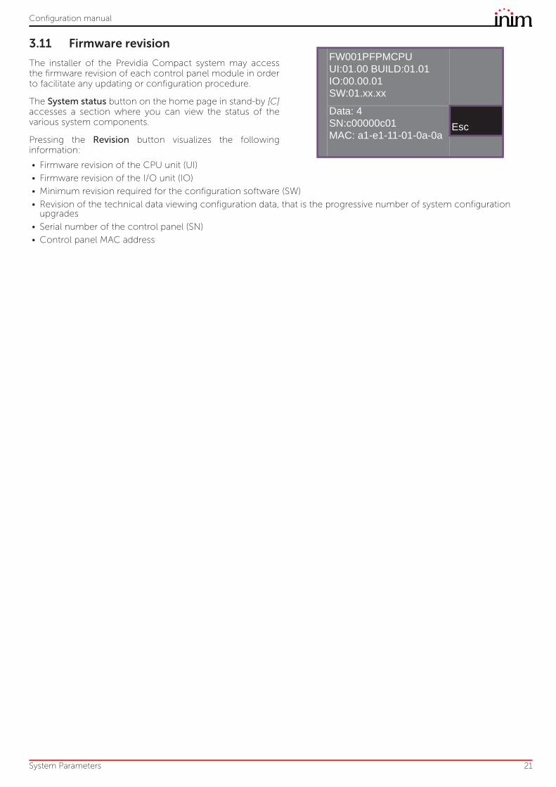
3.11 Firmware revision
The installer of the Previdia Compact system may accessthe firmware revision of each control panel module in orderto facilitate any updating or configuration procedure.
The System status button on the home page in stand-by [C]accesses a section where you can view the status of thevarious system components.
Pressing the Revision button visualizes the followinginformation:
• Firmware revision of the CPU unit (UI)
• Firmware revision of the I/O unit (IO)
• Minimum revision required for the configuration software (SW)
• Revision of the technical data viewing configuration data, that is the progressive number of system configuration upgrades
• Serial number of the control panel (SN)
• Control panel MAC address
FW001PFPMCPUUI:01.00 BUILD:01.01IO:00.00.01SW:01.xx.xx
Data: 4SN:c00000c01MAC: a1-e1-11-01-0a-0a
Esc
22 Parameters of devices and their groupings
Fire detection and extinguishant system
Chapter 4
Parameters of devices and their groupings
The configuration of the devices connected to the loops and the output/input terminals of the Previdia Compact controlpanel takes into consideration both the setting of parameters, which vary depending on whether the device is an input oroutput device, as well as their grouping (zones for the points and output groups for the outputs).
These operations can be carried out in two ways:
- via the “Configuration” menu (paragraph 2.3), by selecting the section relative to the type of connection with the control panel (loop or “I/O”) and accessing the programming sections until you select the device concerned
- via the “Modify” menu (paragraph 2.4), for the direct programming of the devices.From this menu you can also program the logical groupings (zones and output groups)
4.1 Loop point parameters
The parameters of each device connected to one of the two loops are only available after an enrolling operation whichallows the control panel to have a basic loop configuration (paragraph 3.4.1).
At this point the parameters of the enrolled points can be reached in two ways:
- through the “Configuration” menu, by selecting the section relative to one of the two loops and pressing Auto-configure, Add/Change to access a list of the loop points.Selecting a loop point enables the Program button.
- through the “Modify” menu and by pressing the Point button.The screen will show the two control-panel loops and their statuses.Selecting a loop enables the Program button for the parameter settings of the single loop (refer to paragraph 3.4.3 Loop Parameters), and the View button for access to the assigned points. This button allows you to view a list of all the devices on the loop and their statuses.Selecting a loop device enables the Program button for the parameter settings, and the Copy on… button to copy the settings of the selected point (refer to paragraph 4.5).
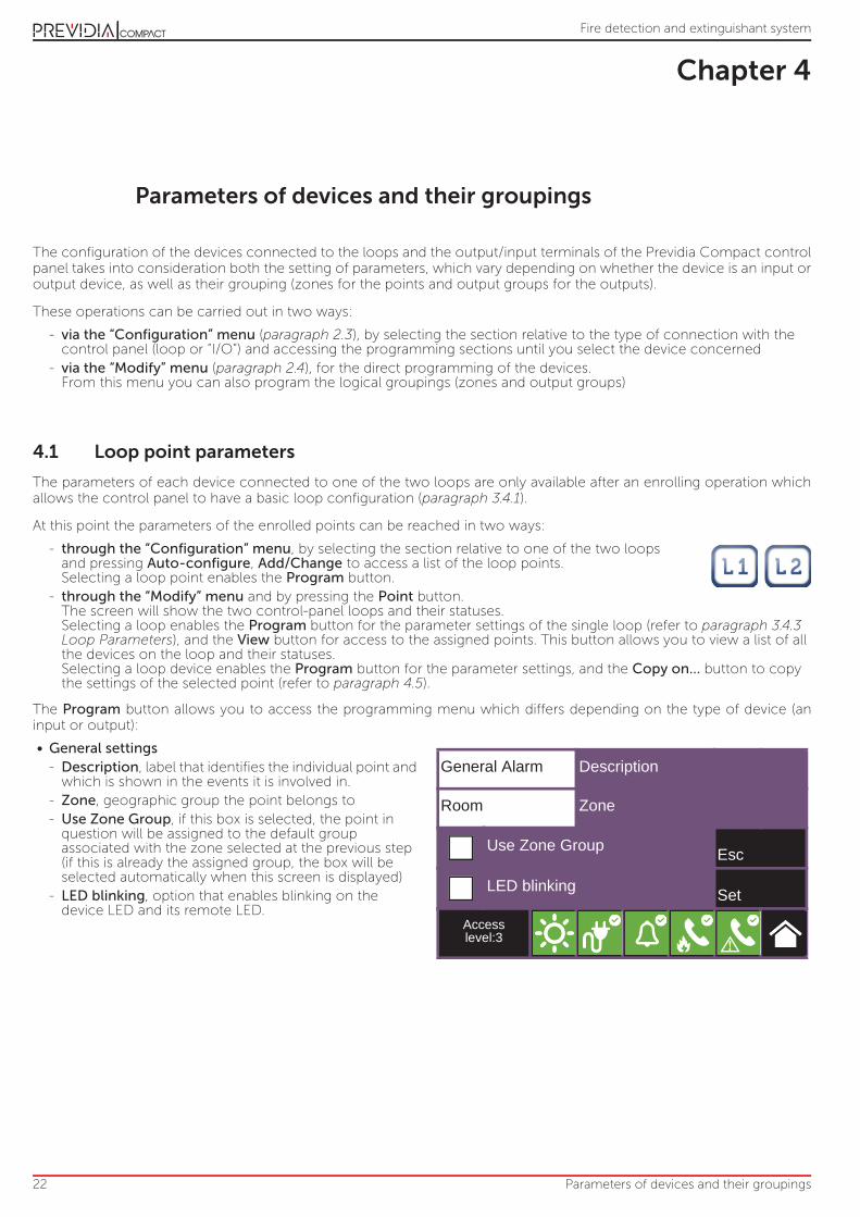
The Program button allows you to access the programming menu which differs depending on the type of device (aninput or output):
• General settings- Description, label that identifies the individual point and
which is shown in the events it is involved in.
- Zone, geographic group the point belongs to
- Use Zone Group, if this box is selected, the point in question will be assigned to the default group associated with the zone selected at the previous step (if this is already the assigned group, the box will be selected automatically when this screen is displayed)
- LED blinking, option that enables blinking on the device LED and its remote LED.
General Alarm Description
Room Zone
Use Zone Group Esc
LED blinking Set
Access level:3

Configuration manual
Parameters of devices and their groupings 23
• Input parameters- Mode, determines the type of event generated by
activation of the input.
- Group activated, indicates the group that will activate following input activation.
- Prealarm, determines when activation of the input will start the associated prealarm time.The possible values are: “Never”, “In day mode” and “Always”.
- Resettable, where present, if activated, the event generated by the activation of the input will reset when the terminal resets.
• Output parameters- Type, determines the way in which the output will be
conditioned by bypass and silence operations by type
- Group activating the output, group whose activation determines the activation of the output
- Silenceable, if selected, once the output is activated it can be deactivated by silencing the control panel
- Pattern, pressing this button accesses the successive screen, which allows you to set the activation pattern for each output status.The available output statuses are “Stand-by”, “Warning”, “Prealarm” and “Alarm”.
4.2 Parameters of control panel terminals
It is possible to set the parameters of an “I/O” terminal only after the line has been configured and the type of deviceconnected to it specified (paragraph 3.6). The programming of the parameters varies according to the specified choice.
The parameters of each device connected to the terminals on-board the control panel (I/O lines and relays) can bereached in two ways:
- via the “Configuration menu”, selecting the section relative to the terminal shows the section with the list of terminals.
- via the “Modify” menu and pressing the I/O Lines button.Two pages will be displayed, navigable with the arrow keys, with a list of all the configured devices and their statuses.
The Program button is available for each terminal and allows access to the input/output programming menu:
• General settings- Description, label that identifies the individual point and
which is shown in the events it is involved in.
- Zone, geographic group the point belongs to
- Use Zone Group, if this box is selected, the point in question will be assigned to the default group associated with the zone selected at the previous step (if this is already the assigned group, the box will be selected automatically when this screen is displayed)
Alarm Mode
Generic alarm Group activated
Always Prealarm Esc
Set
Access level:3
Alarm Type
Generic alarm Group activating the output
Silenceable Esc
Pattern Set
Access level:3
General Alarm Description
Room Zone
Use Zone Group Esc
Set
Access level:3

24 Parameters of devices and their groupings
Fire detection and extinguishant system
• Input parameters- Mode, determines the type of event generated by
activation of the input.
- Group activated, indicates the group that will activate following input activation.
- Prealarm, determines when activation of the input will start the associated prealarm time.The possible values are: “Never”, “In day mode” and “Always”.
- Resettable, where present, if activated, the event generated by the activation of the input will reset when the terminal resets.
• Output parameters- Type, determines the way in which the output will be
conditioned by bypass and silence operations by type
- Group activating the output, group whose activation determines the activation of the output
- Silenceable, if selected, once the output is activated it can be deactivated by silencing the control panel
- Pattern, pressing this button accesses the successive screen, which allows you to set the activation pattern for each output status.The available output statuses are “Stand-by”, “Warning”, “Prealarm” and “Alarm”.
4.3 Zone parameters
Pressing the Zone button in the device parameter settings menu accesses the list of all the control panel zones and theirstatuses.
Selecting a zone enables the Program button to set the parameters, and the Copy on… button to copy the settings ofthe selected zone (refer to paragraph 4.5 Replicate programming procedure).
The parameters available for programming the zone are:
• Description of the zone
• Pre-alarm (sec), length of pre-alarm signal for the zone, in seconds. The zone will trigger an alarm when the set time expires.
• Investigation (sec), length of investigation time, in seconds. Activation of the investigation command during a prealarm, interrupts prealarm time and starts the investigation time.
• Direct alarm on second prealarm, option that, if activated, generates an alarm signal as soon as two detectors, regardless of the zone they belong to, go into prealarm status.Otherwise the alarm condition will activate at the end of the first prealarm time.
• Alarm on second device only, option that, if activated, will activate an alarm signal only after two detectors belonging to the zone have activated.The first detector will generate a prealarm signal with no time count.
4.4 Output group parameters
Pressing the Group button on the device parameter settings menu accesses the list of all the output groups and theirstatuses.
Selecting a group enables the Program button to set the parameters, and the Copy on… button to copy the settings ofthe selected group (refer to paragraph 4.5 Replicate programming procedure).
Alarm Mode
Generic alarm Group activated
Always Prealarm Esc
Set
Access level:3
Alarm Type
Generic alarm Group activating the output
Silenceable Esc
Pattern Set
Access level:3
Zone x Description
Prealarm (sec) Investigate (sec)
030 120
Direct alarm on second prealarm Esc
Alarm on second device only Set
Access level:3

Configuration manual
Parameters of devices and their groupings 25
The parameters available for programming the group are:
• Description of the group
• Delay (sec), duration of the delay (in seconds) before activation of the outputs belonging to the group after the activation of the group itself
• Pulse, option that determines that pulse signals will activate the group of outputs (once the group has been activated, the outputs associated with it will remain active for the specified time and then return to the stand-by status).If activated, you must specify the duration of the pulse activation signal (in the box at the bottom)
4.5 Replicate programming procedure
The Previdia Compact control panel allows you to copy theprogramming of a single element (point, zone, group) andreplicate it on other elements in its category and group.
Accessing the screen of the group of elements undergoingprogramming (in index order) and selecting one of themenables the Program button to modify the parameters, andthe Copy on… button to copy the programming.
The Copy on... button opens a window that provides threeoptions:
• Single item, if activated, the programming will be replicated on the element with the index indicated in the box next to it.
• Range, if activated the programming will be replicated on the elements whose indexes belong to the interval indicated in the boxes at the side.
• All, if activated the programming will be replicated in all the elements of the same group of which the selected element is part
Following the selection of one of these options and after pressing the Set button, all copied settings, except thedescription, will be applied to the programming of the desired elements.
Output group x Description
0001 Delay (sec)
Pulse Esc
0030 Length (sec) Set
Access level:3
N. Zone Status1 Zone 1 Stand-by2 Zone 2 Stand-by3 Zone 3 Stand-by4 Zone 4 Stand-by5 Zone 5 Stand-by6 Zone 6 Stand-by
Program Copy on... Esc
Access level:3
Single element 0002 Index
RangeFrom To
0001 0002
All Esc Set

26 Commissioning
Fire detection and extinguishant system
Chapter 5
Commissioning
The commissioning phase is a set of tests and verifications which are necessary to ensure the full efficiency and properfunctioning of the system as specified in the executive project. This phase is essential and must be performed in ascrupulously in accordance the regulatory requirements of the country where the system is installed and in full respect ofthe recommendations herein.
Ensure the test and verification procedures are performed only after securing the system and after having verified thatany device activations controlled by the system will not cause any conditions of danger, and that all the buildingoccupants who can be reached by the audible and visual signalling have been preventively informed.
Ensure that the person who is responsible for the security of the building where the tests and inspections are beingcarried out has taken countermeasures to avoid any situations of panic or distress for the building occupants.
5.1 Testing the Control panel
It is necessary to check the functionality status of the front plate by first checking the information supplied on the screenand LEDs and then by inspecting the efficiency of the command devices (user-interface buttons, access keys, etc.):
• Check the functionality status of the screen and ensure that the information provided is clear.
• Ensure that the descriptions of the various zones, points and system elements entered during the data-entry phase are correct, and that the information provided on the screen clearly indicates any detectable conditions of danger.
• Check that there are no indications present of faults, alarms or anomalies of any type whatsoever. In the event of such indications, proceed with the removal of the causes of faults and anomalies.
• Check the status the functionality of the LEDs and buzzer. The front panel provides a button for the simultaneous activation of all the LEDs and buzzer thus allowing evaluation of their efficiency (refer to the description of the User Interface).
• Check the efficiency of the front-plate buttons and keys.
• Check the status of the power-supply sources (mains and batteries) and the control panel current draw.
For control of the power-supply parameters you can:
- access the configuration menu (refer to paragraph 2.3) and touch the appropriate icon on the configuration screen of the control panel.
- tap on the power grid icon on the status bar
The sections show the voltages, currents and temperatures of the various elements:
[A]Internal temperature and battery
charge voltages
[B]Section containing a list of
current faults
[C]Battery parameters (internal
resistance, voltage, status and current)
[D]Voltage and output current of
the power supply
[E]
Button, available only for Access Level 3 (installer), allows
immediate battery tests (which normally runs every 10 minutes)
27.6V40°C
Low battery voltage
40°CTest
Output27.9V0.2A
CHARGING0.53A, 0mOhm26.5V, 29°C
Esc
Access level:3
A
B
D
C
E
Configuration manual
Commissioning 27
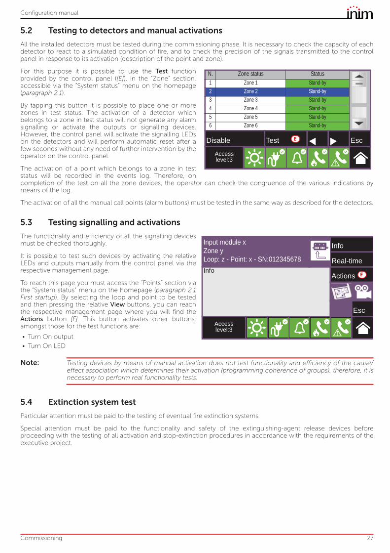
5.2 Testing to detectors and manual activations
All the installed detectors must be tested during the commissioning phase. It is necessary to check the capacity of eachdetector to react to a simulated condition of fire, and to check the precision of the signals transmitted to the controlpanel in response to its activation (description of the point and zone).
For this purpose it is possible to use the Test functionprovided by the control panel ([E]), in the “Zone” section,accessible via the “System status” menu on the homepage(paragraph 2.1).
By tapping this button it is possible to place one or morezones in test status. The activation of a detector whichbelongs to a zone in test status will not generate any alarmsignalling or activate the outputs or signalling devices.However, the control panel will activate the signalling LEDson the detectors and will perform automatic reset after afew seconds without any need of further intervention by theoperator on the control panel.
The activation of a point which belongs to a zone in teststatus will be recorded in the events log. Therefore, oncompletion of the test on all the zone devices, the operator can check the congruence of the various indications bymeans of the log.
The activation of all the manual call points (alarm buttons) must be tested in the same way as described for the detectors.
5.3 Testing signalling and activations
The functionality and efficiency of all the signalling devicesmust be checked thoroughly.
It is possible to test such devices by activating the relativeLEDs and outputs manually from the control panel via therespective management page.
To reach this page you must access the “Points” section viathe “System status” menu on the homepage (paragraph 2.1First startup). By selecting the loop and point to be testedand then pressing the relative View buttons, you can reachthe respective management page where you will find theActions button [F]. This button activates other buttons,amongst those for the test functions are:
• Turn On output
• Turn On LED
Note: Testing devices by means of manual activation does not test functionality and efficiency of the cause/effect association which determines their activation (programming coherence of groups), therefore, it isnecessary to perform real functionality tests.
5.4 Extinction system test
Particular attention must be paid to the testing of eventual fire extinction systems.
Special attention must be paid to the functionality and safety of the extinguishing-agent release devices beforeproceeding with the testing of all activation and stop-extinction procedures in accordance with the requirements of theexecutive project.
N. Zone status Status1 Zone 1 Stand-by2 Zone 2 Stand-by3 Zone 3 Stand-by4 Zone 4 Stand-by5 Zone 5 Stand-by6 Zone 6 Stand-by
Disable Test Esc
Access level:3
E
Input module xZone yLoop: z - Point: x - SN:012345678
Info
Real-timeInfo
Actions
Esc
Access level:3
F

28 Maintenance
Fire detection and extinguishant system
Chapter 6
Maintenance
For correct and efficient management of the system it is necessary to carry out periodic maintenance in accordancewith the regulatory requirements of the country where the system is installed and in full respect of the recommendationsherein.
For the frequency of the maintenance operations it is necessary to adhere to the applicable regulations. However, themanufacturer recommends that tests are performed on each point, component and element of the system at least oncea year.
6.1 Testing the control panel
Work through the steps for control-panel test procedure as described in the commissioning section (paragraph 5.1Testing the Control panel).
Additionally, consult the events log and check for the presence of fault or alarm conditions which must be investigated.
6.2 Testing the detectors
As well as the tests which must be performed during the commissioning phase (paragraph 5.2 Testing to detectors andmanual activations), it is also necessary to check the contamination level in smoke detectors.
The management and configuration software provides a loop diagnostic function which allows you to gather thecontamination values of the various devices in such a way to decide when cleaning is necessary.
Refer to the Programming manual for details regarding the diagnostic function and the detector manual for theinstructions regarding cleaning operations.
6.3 Manual activation test
Work through the same tests as recommended in the commissioning section (paragraph 5.2 Testing to detectors andmanual activations).
6.4 Testing signalling and activations
Work through the same tests as indicated in the commissioning section (paragraph 5.3 Testing signalling and activations).
6.5 Testing the extinction system
Work through the same tests as recommended in the commissioning section (paragraph 5.4 Extinction system test).

Configuration manual
Maintenance 29

30 Maintenance
Fire detection and extinguishant system

User’s manual
31

32
Fire detection and extinguishant system
Centobuchi, via Dei Lavoratori 10
63076 Monteprandone (AP) Italy
Tel. +39 0735 705007 _ Fax +39 0735 704912
[email protected] _ www.inim.biz
DCMCINE0PREVIDIAC-100-20180910
ISO 9001 Quality Management
certified by BSI with certificate number FM530352