analog front-end direct conversion receiver for 802.11b ... · ieee 802.11b standard • 802.11b...
TRANSCRIPT

Analog Front-End Direct Conversion Receiver for
802.11b WiFi ApplicationsDaniel Cohen, Aaron Rocca, & AJ Shammami
April 18, 2011
1

IEEE 802.11b Standard
• Wireless standard for data transmission– Supports 1 and 2 Mbits/sec utilizing DBPSK and
DQPSK respectively– Additional Rates of 5.5 and 11 Mbits/sec are
achieved using CCK modulation frequency spreading
2

IEEE 802.11b Standard
• 802.11b Channels– Composed of 14 channels at frequencies 2.412-
2.484 GHz spaced 5 MHz apart and 22 MHz wide– In North America only first 11 channels are used
3

IEEE 802.11b Receiver Specifications
• Input Range -83/-77 dBm to -10 dBm for 5 MHz channel spacing and 11Mb/s
• Adjacent Channel Rejection– Adjacent channels defined as ±25 MHz apart– Rejection must be 27 dB or greater
4

Receiver Architecture
5

LNA Design
6
LNA SpecificationsNF 2.3-2.4 dB
S11 < -10 dB
S21 21-22 dBGain 21-22 dBP1dB -26 dBm
Ranges Quoted for 2.4-2.5 GHz

Active Balun Design
7
Balun SpecificationsNF 7.4 dB
Max Phase Difference 4 degrees
Max Amplitude Difference 4%
Gain 12 dBRanges quoted for 2.4-2.5GHz and
-10 dBm input

Mixer Design
8

Mixer Specifications
9

Mixer Specifications
10
Mixer SpecificationsNF(dsb) 11.25 dB
Conversion Gain 16.9 dB
IIP3 -4.83 dBm
P1dB -13.5 dBm
LO->RF Isolation -97 dBLO->IF Isolation -80 dB

Local Oscillators for 802.11b
11
• DQPSK received signal– Requires both in-phase
and quadrature (I/Q) LO signals• LO must lock to 11 different frequencies
– 1 center frequency per channel• LO cannot drift much due to 5MHz channel
separationLO should be a Phase-Locked Loop (PLL)

Quadrature Voltage-Controlled Oscillator (QVCO)
12
VCO Specifications
Phase Noise @ ∆f = 1MHz -118 dBc/Hz
VCO Gain, Kv 220 MV/Hz
Voltage Range 550mV – 1.2V

Phase-Locked Loop (PLL)
13
• Fractional-N Divider– Minimizes Noise– Allow higher FREF
• 3rd order ΣΔ Modulator– Prevents spurs
Type 2, 2nd order PLL

PLL Loop Transfer Function
14

PLL Simulation Results
15

Our Receiver
16

Gm-C Transconductance Cell
17

5th Order Elliptic Filter• Fully Differential Gm-C Filter• Variable gain of from 0-25dB• Roll-off ≈ -122dB/dec
18

Filter Bode Plot
• Click to edit Master text styles– Second level
• Third level– Fourth level
» Fifth level
19
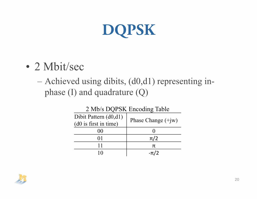
DQPSK
• 2 Mbit/sec– Achieved using dibits, (d0,d1) representing in-
phase (I) and quadrature (Q)
20
2 Mb/s DQPSK Encoding TableDibit Pattern (d0,d1) (d0 is first in time) Phase Change (+jw)
00 001 π/211 π10 ‐π/2

CCK
• Direct Extension of DQPSK• Allows frequency spreading of data
resulting in bandwidth of 5.5 and 11 Mb/s
21
c {e j (1 2 3 4 ),e j (1 3 4 ),e j (1 2 4 ),e j(1 4 ),e j(1 2 3 ),e j(1 3 ),e j (1 2 ),e j (1 )}

Symbol Transmission
22

Symbol Transmission
23

Symbol Transmission
24

Symbol Transmission
25

Symbol Transmission
26

Successful Data Recovery
27

Layout
28

Overall Results
29
Front End Comparison This Work* [40] [41]
NFdsb 3.2 dB* 4.1 dB 5.2 dBGain 61 dB 25.1 dB 89 dB
Power 37 mW 22.7 mW 108 mWSupply Voltage 1.2 V 1.8 V 1.8 V
Process IBM .13 um CMOS TSMC .18 um CMOS IP6M .18 um CMOS*Simulation results with ideal LO

References[1] T. Nguyen, S. Lee, “A Low Voltage, Low Power CMOS Fifth Order Elliptic Low Pass Gm-C Filter For Direct
Conversion Receiver” Asia Pacific Microwave Conference, 2003.[2] C. Langton, R. Menendez, “Phase Shift Keying Modulations” All About Modulation – Part I, December 2005,
pp. 7-25.[3] B. Pearson, “Complimentary Code Keying Made Simple,” Intersil Corp., Palm Bay, FL,Rep. AN9850.1, May 2000.[4] Z. Gao, M. Yu, F Lai, Y. Ye et al., “A High Q Gm-C Filter for Multi-band Wireless Applications,”8th
International Conference on Solid State and Integrated Circuit Technology, pp. 1733, April 2007.[5] B. Razavi, Design of Analog CMOS Integrated Circuits. Boston, MA: McGraw Hill, 2001, pp. 291-344.[6] T.Lee, The Design of CMOS Radio-Frequency Integrated Circuits. Cambridge University Press, 1998.[7] G. Kathiresan, C. Toumazou, B Gilbert., “Trade-Offs in Analog Circuit Design: The Designer’s Companion,”Trade_offs in CMOS Mixer Design, Kluwer Academic Publishers, April 2007, pp. 787-819.[8] B. Wei, Y. Dai, Y. Lu, X. Zhang, H. Liu, et al., “A Sub 1V High Gain Low Noise CMOS DownconversionFolded Mixer for 2.4 GHz ISM Band Appliactions” International Symposium on Intelligent Information Technology Application Workshop, 2008 pp. 689-692.[9] H. Darabi, A. Abidi, “Noise in RF-CMOS Mixers: A Simple Physical Model” IEEE Transactions on Solid State Circuits, vol. 35 No. 1, Janurary, 2000 pp. 15-25.[10] H. Darabi, J. Chiu, “A Noise Cancellation Techinique in Active RF-CMOS Mixers” IEEE Journal of Solid State Circuits, vol. 40 No. 12, December, 2005 pp. 2628-2632.[11] C. Kim, H. Son, B. Kang, “A 2.4 GHz Current Reused CMOS Balun Mixer” IEEE Microwave and Wireless Components Letters, vol. 19 No. 7, July 2009 pp. 464-466.[12] T. Lo, C. Hung, “Gm-C Filters,”1V CMOS Gm-C Filters, Springer, 2009 pp. 47-88.
30

References[13] C. Hung, K. Halonen, M. Ismail, et al., “A Low Voltage, Low Power CMOS Fifth-Order Elliptic Gm-C Filter for Baseband Mobile, Wireless Communication” IEEE Transactions on Circuits and Systems For Video Technology, vol. 7 No. 4, August, 1997 pp. 584-598.[14] E. Hegazi, H. Sjoland, A. Abidi, et al., “A Filtering Technique to Lower LO Oscillator Phase Noise” IEEE Journal of Solid State Circuits, August 2002 pp. 1921-1930.[15] K. Lee, B. Park, H. Lee, M. Yoh, et al., “Phase Frequency Detectors for Fast Frequency Acquisition in Zero-Dead_Zone CPPLLs for Mobile Communication Systems” Samsung Corp., Korea, 449-711.[16] T. Lin, C. Ti, Y.Liu, et al., “Dynamic Current-Matching Charge Pump and Gated Offset Linearization Technique for Delta-Sigma Fractional-N PLLs” IEEE Transactions on Circuits and Systems – I: Regular Papers, vol. 56 No. 5, May, 2009 pp. 877-885.[17] K. Vavelidis, I. Vassilou, T. Georgantes, A. Yamanaka, S. Kavadias, G. Kamoulakos, C. Kapnistis, Y. Kokolakis, A. Kyranas, P. Merakos, I. Bouras, S. Bouras, S. Plevridis, N. Haralabidis, S.A. Athena Semi, G. Alimos , et al., “A Dual Band 5.15-5.35 GHz .18µm CMOS Tranceiver for 802.11a/b/g wireless LAN” Journal of IEEE Solid State Circuit, vol. 39 No. 7, June 2004 pp. 1180-1184.[18] J. Gil, S. Song, H. Lee, H. Shin, et al., “A -119.2 dBc at 1 MHz, 1.5 mW, Fully Integrated, 2.5 GHz, CMOS VCO using Helical Inductors” IEEE Microwave and Wireless Components Letters, vol. 13 No. 11, November 2003, pp. 457-459.[19] D. Leenaerts, C. Dijkmans, M. Thompson, Res. Phillips, Eindhoven, et al., “A .18µm CMOS 2.45 GHz Low Power Quadrature VCO with 15% Tuning Range,”2002 IEEE Radio Frequency Integrated Circuits (RFIC) , August 2002, pp. 67-70.[20] J. Long, J. Foo, R. Weber, et al., “A 2.4 GHz Low-Power Low Phase Noise CMOS LC VCO,” Department of Electrical Engineering and Computer Engineering, Iowa State Univ. Ames, IA, 2004.
31

References[21] C. Barret, “Fractional/Integer-N PLL Basics,” Texas Instruments, SWRA029[22]S. Huang, H. Ma, Z. Whang, et al., “Modeling and Simulation to the Design of Sigma Delta Fractional-N Frequency Synthesizer,” Department of Electronics Engineering, Tsinghua University, Beijing [23] K. Shu, E. Sanchez-Sinencio, J. Silvia-Martinez, S. Embabi, et al., “A 2.4 GHz Monolithic Fractional-N Frequency Synthesizer with Robust Phase-Switching Prescaler and Loop Capacitance Multiplier,”IEEE Journal of Solid State Circuits , vol. 38, No. 6, June 2003, pp. 866-874.[24] G.Zhiqiang, “Design of CMOS Integrated Q-Enhanced RF Filters for Multi-Band/Mode Wireless Applications,” Department of Micro-electronics of Harbin Institute of Technology, China.[25] J.H. Mikkelsen, T.E. Kolding, T. Larsen, T. Klingenbrunn, K.I. Pederson, P Mogensen, et al., “Feasibility Study of DC Offset Filtering for UTRA-FDD/WCDMA Direct Conversion Receiver,” RISC Group and CPK, Aalborg University, Aalborg East, Denmark.[26]B. Razavi, “Design Considerations for Direct Conversion Receivers, “IEEE Transactions on Circuits and Systems – II Analog and Digital Signal Processing, vol. 44, No. 6, June 2007, pp. 428-435.[27]N. Poobuapheun, “LNA and Mixer Designs for Multi-Band Receiver Front Ends,” Electrical Eng. And Comp. Science, Univ Cal. Berkley, August 1, 2009.[28]A. Hu, Multi Modulus Divider in Fractional-N Frequency Synthesizer for Direct Conversion DVB-H Receiver,” Ohio State Univ. 2007[29] A.Z. Al-Banna, T.R. Lee, J.L. LoCicero, D.R. Ucci, et al., “11 Mbps CCK – Modulated 802.11b Wi-Fi Spectral Signature and Interference,” IEEE Conference on Electro/Information Technology, December 2006, pp. 313-317.[30] M. Perrot, “Short Course on Phase Locked Loops and their Applications”[31] MIT Open Courseware Lecture Notes from High Speed Communication Circuits and Systems.
32

References[32] J. Rogers, C. Plett, F. Dai, et al., “Integrated Circuit Design For High Speed Frequency Sysnthesis,” ArtechHouse INC, 2006.[33] J. LaRocca, R. LaRocca, “802.11 Demystified, WI-FI Made Easy,” McGraw Hill TELECOM, 2002.[34] B. Skylar, “Digital Communications, Fundamentals and Applications,” University of California, Los Angeles, Prentice Hall PTR, 2001.[35] E. Megazi, J. Rael, A. Abidi, et al., “The Designer’s Guide to High Purity Oscillators,” Kluwer Academic Publishers, 2005[36] A. Lacaita, S. Levantino, C. Samori, et al., “Integrated Frequency Synthsizers for Wireless Systems,” Cambridge University Press, 2007.[37] D. Kim, J. Kim, J.O. Plouchart, D. Lim, et al., “A Low Power mmWave CML Prescaler in 65nm SOI CMOS Technology,”IEEE Journal, 2008[38]B. Miller, R. Conley, “A Multiple Modulator Fractional Divider,”IEEE Transactions of Instrumentation and Measurements , vol. 40, No. 3, June 1991, pp. 578-583.[39]M. Z. Al Sabbagh, “A .18µm Phase / Frequency Detector and Charge Pump Design for Digital Video Broadcasting for Handheld’s Phase Locked Loop Systems,” Ohio State University, 2007.
33

Thank You/QuestionsWe would like to acknowledge the following for theirhelp with cadence simulations and design methodologies:
Professor Wentzloff, Mohammad Ghahramani, Jeffery Fredenburg, Jonathan Brown, Nick Collins, David Lin, & Ben Rhew
34