analog output interfaces - scale service · plc and analog output interfaces d14884200a ... quantum...
TRANSCRIPT
®
PLC and Analog Output Interfaces
D14884200A 02.05.00
COPYRIGHT
Copyright 2003 Mettler-Toledo, Inc. This documentation contains proprietary information of Mettler-Toledo, Inc. It may not be copied in whole or in part without the express written consent of Mettler-
Toledo, Inc.
METTLER TOLEDO reserves the right to make refinements or changes to the product or manual without notice.
U.S. Government Restricted Rights Legend: This software is furnished with Restricted Rights. Use,
duplication, or disclosure of the Software by the U.S. Government is subject to the restrictions as set forth in subparagraph (C) (1) (ii) of the Rights in Technical Data and Computer Software clause at 40 C.F.R.
Sec. 252.227-7013 or in subparagraphs (c) (1) and (2) of the Commercial Computer Software-Restricted Rights clause at 40 C.F.R. Sec. 52-227-19, as applicable.
FCC Notice
This device complies with Part 15 of the FCC Rules and the Radio Interference Requirements of the Canadian Department of Communications. Operation is subject to the following conditions: (1) this
device may not cause harmful interference, and (2) this device must accept any interference received, including interference that may cause undesired operation.
This equipment has been tested and found to comply with the limits for a Class A digital device,
pursuant to Part 15 of FCC Rules. These limits are designed to provide reasonable protection against harmful interference when the equipment is operated in a commercial environment. This equipment
generates, uses, and can radiate radio frequency energy and, if not installed and used in accordance with the instruction manual, may cause harmful interference to radio communications. Operation of this
equipment in a residential area is likely to cause harmful interference in which case the user will be required to correct the interference at his or her own expense.
ORDERING INFORMATION
It is most important that the correct part number is used when ordering parts. Parts orders are machine processed, using only the part number and quantity as shown on the order. Orders are not edited to
determine if the part number and description agree.
TRADEMARKS
METTLER TOLEDO®, JAGUAR®, JAGXTREME® and DigiTOL® are registered trademarks of Mettler-Toledo, Inc. All other brand or product names are trademarks or registered trademarks of their respective
companies.
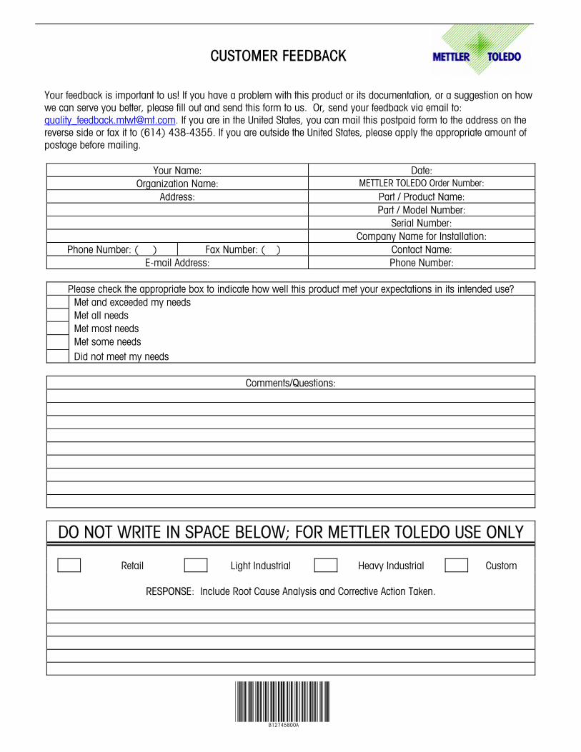
CUSTOMER FEEDBACK
Your feedback is important to us! If you have a problem with this product or its documentation, or a suggestion on how we can serve you better, please fill out and send this form to us. Or, send your feedback via email to: [email protected]. If you are in the United States, you can mail this postpaid form to the address on the reverse side or fax it to (614) 438-4355. If you are outside the United States, please apply the appropriate amount of postage before mailing.
Your Name: Date:
Organization Name: METTLER TOLEDO Order Number: Address: Part / Product Name:
Part / Model Number: Serial Number:
Company Name for Installation: Phone Number: ( ) Fax Number: ( ) Contact Name:
E-mail Address: Phone Number:
Please check the appropriate box to indicate how well this product met your expectations in its intended use? Met and exceeded my needs Met all needs Met most needs Met some needs Did not meet my needs
Comments/Questions:
DO NOT WRITE IN SPACE BELOW; FOR METTLER TOLEDO USE ONLY
Retail Light Industrial Heavy Industrial Custom
RESPONSE: Include Root Cause Analysis and Corrective Action Taken.
B12745800A
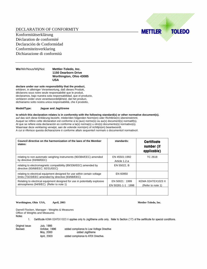
DECLARATION OF CONFORMITY Konformitätserklärung Déclaration de conformité Declaración de Conformidad Conformiteitsverklaring Dichiarazione di conformità
We/Wir/Nous/Wij/Noi: Mettler-Toledo, Inc. 1150 Dearborn Drive Worthington, Ohio 43085 USA declare under our sole responsibility that the product, erklären, in alleiniger Verantwortung, daß dieses Produkt, déclarons sous notre seule responsabilité que le produit, declaramos, bajo nuestra sola responsabilidad, que el producto, verklaren onder onze verantwoordelijkheid, dat het product, dichiariamo sotto nostra unica responsabilitá, che il prodotto, Model/Type: Jaguar and JagXtreme to which this declaration relates is in conformity with the following standard(s) or other normative document(s). auf das sich diese Erklärung bezieht, mitder/den folgenden Norm(en) oder Richtlinie(n) übereinstimmt. Auquel se réfère cette déclaration est conforme à la (aux) norme(s) ou au(x) document(s) normatif(s). Al que se refiere esta declaración es conforme a la(s) norma(s) u otro(s) documento(s) normativo(s). Waarnaar deze verklaring verwijst, aan de volende norm(en) of richtlijn(en) beantwoordt. A cui si riferisce questa dichiarazione è conforme alla/e sequente/i norma/e o documento/i normativo/i.
Council directive on the harmonization of the laws of the Member states:
standards: Certificate number (if applicable)
relating to non-automatic weighing instruments (90/384/EEC) amended by directive (93/68/EEC)
EN 45501:1992 Article 1.2.a
TC 2618
relating to electromagnetic compatibility (89/336/EEC) amended by directive (93/68/EEC; 92/31/EEC)
EN 55022, B
relating to electrical equipment designed for use within certain voltage limits (73/23/EEC amended by directive (93/68/EEC)
EN 60950
Relating to electrical equipment designed for use in potentially explosive atmospheres (94/9/EC) (Refer to note 1)
EN 50021 : 1999 EN 50281-1-1 : 1998
KEMA 02ATEX1023 X (Refer to note 1)
Worthington, Ohio USA, April, 2003 Mettler-Toledo, Inc. Darrell Flocken, Manager - Weights & Measures Office of Weights and Measures Notes:
1. Certificate KEMA 02ATEX1023 X applies only to JagXtreme units only. Refer to Section (17) of the certificate for special conditions. Original issue: July, 1995 Revised: October, 1996 added compliance to Low Voltage Directive May, 2000 added JagXtreme April, 2003 added compliance to ATEX Directive.

PRECAUTIONS
WARNING ONLY PERMIT QUALIFIED PERSONNEL TO SERVICE THIS EQUIPMENT. EXERCISE CARE WHEN MAKING CHECKS, TESTS AND ADJUSTMENTS THAT MUST BE MADE WITH
POWER ON. FAILING TO OBSERVE THESE PRECAUTIONS CAN RESULT IN BODILY HARM.
READ this manual BEFORE operating or servicing this equipment. FOLLOW these instructions carefully. SAVE this manual for future reference. DO NOT allow untrained personnel to operate, clean, inspect, maintain, service, or tamper with this equipment. ALWAYS DISCONNECT this equipment from the power source before cleaning or performing maintenance. CALL METTLER TOLEDO for parts, information, and service.
WARNING FOR CONTINUED PROTECTION AGAINST SHOCK HAZARD CONNECT TO PROPERLY GROUNDED OUTLET ONLY. DO
NOT REMOVE THE GROUND PRONG.
WARNING DISCONNECT ALL POWER TO THIS UNIT BEFORE
REMOVING THE FUSE OR SERVICING.
CAUTION BEFORE CONNECTING/DISCONNECTING ANY INTERNAL ELECTRONIC
COMPONENTS OR INTERCONNECTING WIRING BETWEEN ELECTRONIC EQUIPMENT ALWAYS REMOVE POWER AND WAIT AT LEAST THIRTY (30) SECONDS BEFORE ANY CONNECTIONS OR DISCONNECTIONS ARE MADE. FAILURE TO OBSERVE
THESE PRECAUTIONS COULD RESULT IN DAMAGE TO OR DESTRUCTION OF THE EQUIPMENT OR BODILY HARM.
CAUTION OBSERVE PRECAUTIONS FOR HANDLING ELECTROSTATIC SENSITIVE DEVICES.

NO POSTAGE NECESSARY
IF MAILED IN THE UNITED
STATES
BUSINESS REPLY MAIL
FIRST CLASS PERMIT NO. 414 COLUMBUS, OH
POSTAGE WILL BE PAID BY ADDRESSEE
Mettler-Toledo, Inc. Quality Manager - MTWT P.O. Box 1705 Columbus, OH 43216 USA
Please seal with tape.
CONTENTS
1 Allen-Bradley RIO Option Card ......................................................................... 1-1 Overview............................................................................................................................... 1-1 Data Definition ....................................................................................................................... 1-3 Hardware Setup ................................................................................................................... 1-21 Software Setup ..................................................................................................................... 1-21 Troubleshooting ................................................................................................................... 1-23 Allen-Bradley RIO PCB Parts .................................................................................................. 1-24 Interfacing Examples ............................................................................................................ 1-25
2 PROFIBUS ..................................................................................................... 2-1 Overview............................................................................................................................... 2-1 Data Definition ....................................................................................................................... 2-6 Floating Point Numbers......................................................................................................... 2-20 Hardware Setup ................................................................................................................... 2-25 Software Setup ..................................................................................................................... 2-25 Troubleshooting ................................................................................................................... 2-27 PROFIBUS PCB Parts ............................................................................................................ 2-28 Siemens Simatic S5 Setup Example........................................................................................ 2-29 TI545 Setup Example ........................................................................................................... 2-31 Sample Conversion of IEEE Floating Point Format into Siemens S5 Floating Point Format.............. 2-33
3 Dual Analog Output Option Card ...................................................................... 3-1 JAGXTREME Terminal Dual Analog Output PCB .......................................................................... 3-1 Specifications ........................................................................................................................ 3-1 Installation ............................................................................................................................ 3-2 Setup In the JAGXTREME Terminal ............................................................................................ 3-3 Wiring................................................................................................................................... 3-4 Dual Analog Output PCB Parts ................................................................................................. 3-5
4 Modbus Plus Option Card ............................................................................... 4-1 Overview............................................................................................................................... 4-1 Data Definition ....................................................................................................................... 4-5 Hardware Setup ................................................................................................................... 4-25 Troubleshooting ................................................................................................................... 4-28 Modbus Plus PCB Parts ........................................................................................................ 4-29 Modicon 984-385E Setup Example........................................................................................ 4-30 Quantum 242 02 PLC with NOM 211 00 Module .................................................................... 4-35
5 Appendix....................................................................................................... 5-1 PLC Custom Interface.............................................................................................................. 5-1 JagBASIC to Analog Output Shared Data Interface....................................................................... 5-2

For your notes
Chapter 1: Allen-Bradley RIO Option Card Overview
1 Allen-Bradley RIO Option Card
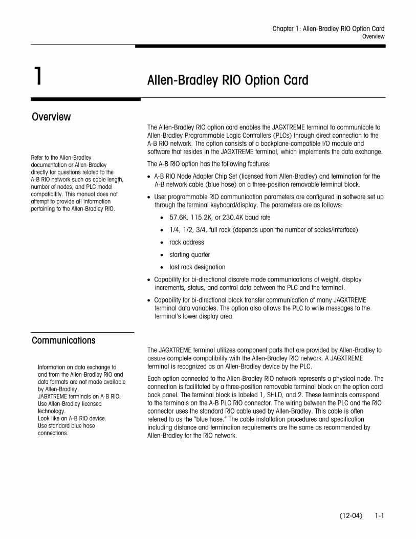
Overview The Allen-Bradley RIO option card enables the JAGXTREME terminal to communicate to Allen-Bradley Programmable Logic Controllers (PLCs) through direct connection to the A-B RIO network. The option consists of a backplane-compatible I/O module and software that resides in the JAGXTREME terminal, which implements the data exchange.
Refer to the Allen-Bradley documentation or Allen-Bradley directly for questions related to the A-B RIO network such as cable length, number of nodes, and PLC model compatibility. This manual does not attempt to provide all information pertaining to the Allen-Bradley RIO.
The A-B RIO option has the following features:
• A-B RIO Node Adapter Chip Set (licensed from Allen-Bradley) and termination for the A-B network cable (blue hose) on a three-position removable terminal block.
• User programmable RIO communication parameters are configured in software set up through the terminal keyboard/display. The parameters are as follows:
• 57.6K, 115.2K, or 230.4K baud rate
• 1/4, 1/2, 3/4, full rack (depends upon the number of scales/interface)
• rack address
• starting quarter
• last rack designation
• Capability for bi-directional discrete mode communications of weight, display increments, status, and control data between the PLC and the terminal.
• Capability for bi-directional block transfer communication of many JAGXTREME terminal data variables. The option also allows the PLC to write messages to the terminal's lower display area.
Communications The JAGXTREME terminal utilizes component parts that are provided by Allen-Bradley to assure complete compatibility with the Allen-Bradley RIO network. A JAGXTREME terminal is recognized as an Allen-Bradley device by the PLC. Information on data exchange to
and from the Allen-Bradley RIO and data formats are not made available by Allen-Bradley. JAGXTREME terminals on A-B RIO: Use Allen-Bradley licensed technology. Look like an A-B RIO device. Use standard blue hose connections.
Each option connected to the Allen-Bradley RIO network represents a physical node. The connection is facilitated by a three-position removable terminal block on the option card back panel. The terminal block is labeled 1, SHLD, and 2. These terminals correspond to the terminals on the A-B PLC RIO connector. The wiring between the PLC and the RIO connector uses the standard RIO cable used by Allen-Bradley. This cable is often referred to as the “blue hose.” The cable installation procedures and specification including distance and termination requirements are the same as recommended by Allen-Bradley for the RIO network.
(12-04) 1-1
METTLER TOLEDO JAGXTREME PLC and Analog Output Interface Technical Manual
Node/Rack Address Although each RIO option represents one physical node, the addressing of the node is defined as a logical rack address. This address is chosen by the system designer, then programmed into the terminal and PLC. The JAGXTREME terminal’s address is programmed through the Configure Options program block in the setup menu.
The terminal’s setup capabilities allow selection of the logical rack address, starting quarter, and designation of the last rack. More than one rack quarter must be used if the terminal’s RIO option is configured to interface with more than one scale, floating point data, or the optional block transfer data. Since up to four scales may be configured to interface with one RIO option, it will occupy four quarters (a full rack). The quarters must be contiguous in a single, logical rack, so the starting quarter must be low enough to accommodate all of the data for the scales in a single, logical rack. The terminal will determine the number of quarters needed for the number of configured scales and chosen data format. It only allows selection of the possible starting quarters.
Data Formats The A-B RIO option card has two types of data exchanges: discrete data and block transfer data.
Discrete data is continuously available for each of the configured scales. Each scale selected to pass data through the RIO option has its own logical rack address to send and receive information to and from the PLC. Discrete data for each scale is always sent even when the optional block transfer data is used.
Block transfer data is available when the option is enabled through the terminal’s setup menu. This data is used to pass information that cannot be sent by the discrete data because of size or process speed limitations. See the Data Definition section for more information.
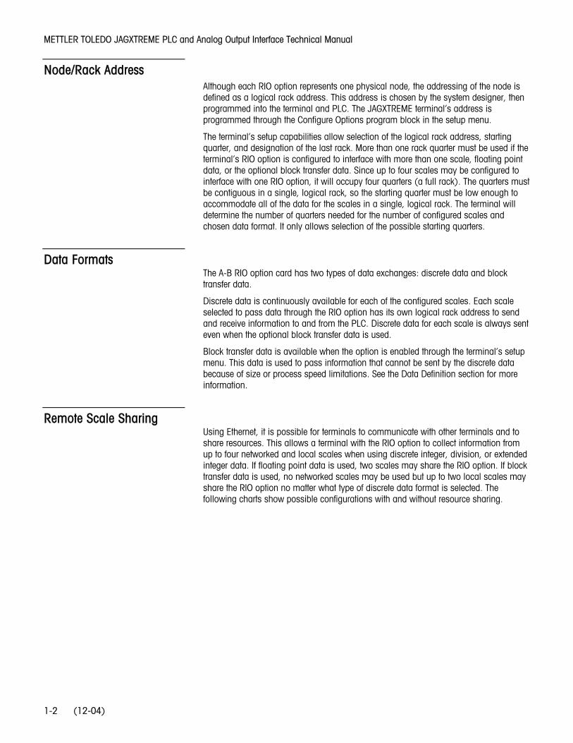
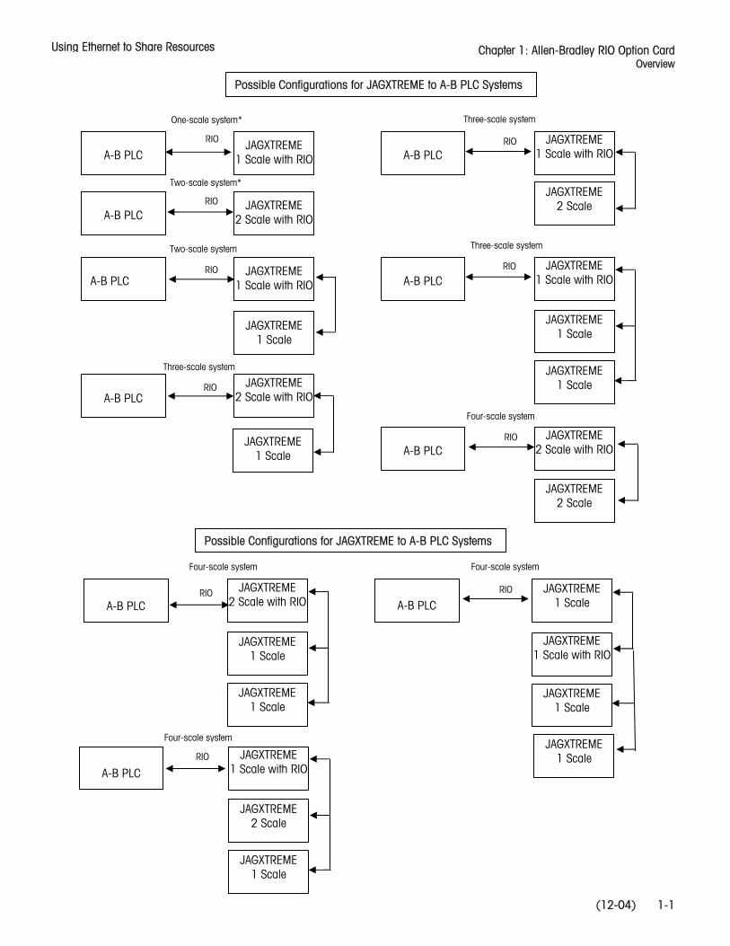
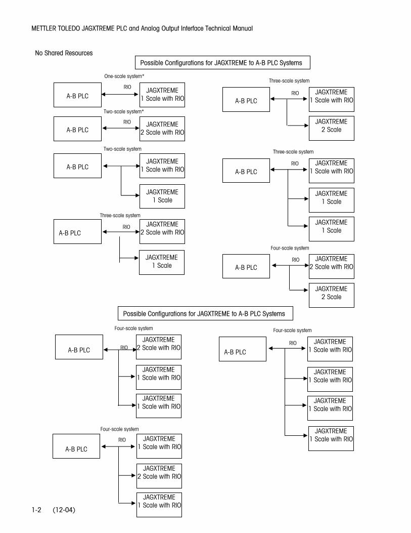
Remote Scale Sharing Using Ethernet, it is possible for terminals to communicate with other terminals and to share resources. This allows a terminal with the RIO option to collect information from up to four networked and local scales when using discrete integer, division, or extended integer data. If floating point data is used, two scales may share the RIO option. If block transfer data is used, no networked scales may be used but up to two local scales may share the RIO option no matter what type of discrete data format is selected. The following charts show possible configurations with and without resource sharing.
(12-04) 1-2
Chapter 1: Allen-Bradley RIO Option Card
Using Ethernet to Share Resources OverviewPossible Configurations for JAGXTREME to A-B PLC Systems
RIO
A-B PLC
JAGXTREME 1 Scale with RIO
A-B PLC
JAGXTREME 2 Scale with RIO
A-B PLC
JAGXTREME 1 Scale with RIO
JAGXTREME 1 Scale
JAGXTREME 1 Scale
JAGXTREME 2 Scale with RIO
A-B PLC
JAGXTREME 2 Scale with RIO
JAGXTREME 2 Scale
RIO
Four-scale system
A-B PLC
JAGXTREME 2 Scale
JAGXTREME 1 Scale with RIO
A-B PLC
JAGXTREME 1 Scale
JAGXTREME 1 Scale with RIO
JAGXTREME 1 Scale RIO
RIO
RIO
RIO
RIO
Three-scale system
Three-scale system
Three-scale system
Two-scale system
Two-scale system*
One-scale system*
A-B PLC
Possible Configurations for JAGXTREME to A-B PLC Systems
Four-scale system Four-scale system
JAGXTREME 1 Scale
JAGXTREME 1 Scale with RIO
JAGXTREME 1 Scale
JAGXTREME 1 Scale
RIO A-B PLC
RIO
A-B PLC
JAGXTREME 1 Scale
JAGXTREME 2 Scale with RIO
JAGXTREME 1 Scale
A-B PLC
JAGXTREME 2 Scale
JAGXTREME 1 Scale with RIO
JAGXTREME 1 Scale
Four-scale system
RIO
(12-04) 1-1
METTLER TOLEDO JAGXTREME PLC and Analog Output Interface Technical Manual
1-2
Four-scale system
A-B PLC
JAGXTREME 1 Scale with RIO
JAGXTREME 1 Scale with RIO
JAGXTREME 1 Scale with RIO
JAGXTREME 1 Scale with RIO
RIO
Three-scale system
RIO A-B PLC
JAGXTREME 2 Scale
JAGXTREME 1 Scale with RIO
A-B PLC
JAGXTREME 1 Scale
JAGXTREME 1 Scale with RIO
JAGXTREME 1 Scale
Three-scale system
RIO
A-B PLC
JAGXTREME 1 Scale with RIO
A-B PLC
JAGXTREME 2 Scale with RIO
A-B PLC
JAGXTREME 1 Scale with RIO
JAGXTREME 1 Scale
JAGXTREME 1 Scale
JAGXTREME 2 Scale with RIO
RIO
RIO
Three-scale system
RIO
RIO A-B PLC
JAGXTREME 2 Scale with RIO
JAGXTREME 2 Scale
Possible Configurations for JAGXTREME to A-B PLC Systems
Four-scale system
Two-scale system
Two-scale system*
One-scale system*
A-B PLC
Possible Configurations for JAGXTREME to A-B PLC Systems No Shared Resources
(12-04)
RIO
A-B PLC
JAGXTREME 1 Scale with RIO
JAGXTREME 2 Scale with RIO
JAGXTREME 1 Scale with RIO
RIO A-B PLC
JAGXTREME 2 Scale with RIO
JAGXTREME 1 Scale with RIO
JAGXTREME 1 Scale with RIO
Four-scale system
Four-scale system
Chapter 1: Allen-Bradley RIO Option Card Data Definition
Data Definition The A-B RIO option card uses two types of data for its communication with PLCs: discrete data and block transfer data. Separate discrete data for each scale is always available. The data transfer is accomplished via the PLC’s I/O messaging. Block transfer data is only available if this data option is enabled through the setup menu. If the block transfer data option is selected, it is provided in addition to the discrete data for each scale. Block transfer data requires “block transfer” ladder sequence programming to accomplish the data transfer between the terminal and PLC.
Data Integrity The JAGXTREME terminal has specific bits to allow the PLC to confirm that data was received without interrupt and the scale is not in an error condition. It is important to monitor these bits. Any PLC code should use them to confirm the integrity of the data received for the scale. Refer to the data charts for specific information regarding the Data OK, update in progress, data integrity bits and their usage.
Discrete Data There are four formats of discrete data available with the A-B RIO option card: integer (wgt), division (div), extended integer (ext), and floating point (flt). Only one type of data format may be selected and used by scales sharing the same A-B RIO option card.
The integer and division formats allow bi-directional communication of discrete bit encoded information or 16 bit binary word (signed integer) numerical values.
The extended integer format allows bi-directional communication of discrete bit encoded information, 21-bit binary word (signed extended integer) numerical read values or 16-bit binary word (signed integer) numerical write values.
The floating-point format allows bi-directional communication of discrete bit encoded information or numeric data encoded in IEEE 754, single precision floating point format.
The format of discrete data will affect the amount of rack space required per scale and the amount used by the RIO option. Integer, division, and extended integer formats require one-quarter rack per scale (two 16-bit words of input and two 16-bit words of output data). One scale would use a quarter rack, two scales would use a half rack, three scales would use three-quarters of a rack, and four scales would use a full rack.
The floating-point format requires more space per scale because floating point data uses two 16-bit words of data to represent just the numeric data alone. The floating point format requires one half rack per scale (four 16-bit words of input and four 16-bit words of output data) in a two-scale system or provides two half-rack sets of data for a single scale. For both, the RIO option requires the use of a full rack for data when the floating point format is selected.
Selection of the appropriate format depends on issues such as the range or capacity of the scale used in the application. The integer format can represent a numerical value up to 32,767. The division format can represent a value up to 32,767 divisions or increments. The extended integer can represent a value over 1,000,000. The floating-point format can represent a value encoded in IEEE 754, single precision floating point format. Floating point is the only format that includes decimal point information as a part of its data. All other formats ignore decimal points. Accommodation of decimal point location must take place in the PLC logic, when it is needed with these formats.
(12-04) 1-3
METTLER TOLEDO JAGXTREME PLC and Analog Output Interface Technical Manual
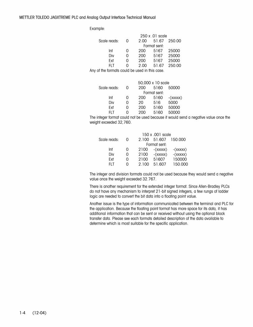
Example:
250 x .01 scale Scale reads: 0 2.00 51.67 250.00
Format sent: Int 0 200 5167 25000 Div 0 200 5167 25000 Ext 0 200 5167 25000 FLT 0 2.00 51.67 250.00
Any of the formats could be used in this case.
50,000 x 10 scale
Scale reads: 0 200 5160 50000 Format sent:
Int 0 200 5160 -(xxxxx) Div 0 20 516 5000 Ext 0 200 5160 50000 FLT 0 200 5160 50000
The integer format could not be used because it would send a negative value once the weight exceeded 32,760.
150 x .001 scale
Scale reads: 0 2.100 51.607 150.000 Format sent:
Int 0 2100 -(xxxxx) -(xxxxx) Div 0 2100 -(xxxxx) -(xxxxx) Ext 0 2100 51607 150000 FLT 0 2.100 51.607 150.000
The integer and division formats could not be used because they would send a negative value once the weight exceeded 32.767.
There is another requirement for the extended integer format. Since Allen-Bradley PLCs do not have any mechanism to interpret 21-bit signed integers, a few rungs of ladder logic are needed to convert the bit data into a floating point value.
Another issue is the type of information communicated between the terminal and PLC for the application. Because the floating point format has more space for its data, it has additional information that can be sent or received without using the optional block transfer data. Please see each formats detailed description of the data available to determine which is most suitable for the specific application.
(12-04) 1-4
Chapter 1: Allen-Bradley RIO Option Card Data Definition
(12-04) 1-5
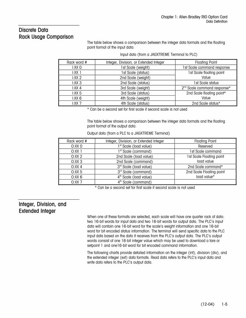
Discrete Data Rack Usage Comparison
The table below shows a comparison between the integer data formats and the floating point format of the input data:
Input data (from a JAGXTREME Terminal to PLC)
Rack word # Integer, Division, or Extended Integer Floating Point I:XX 0 1st Scale (weight) 1st Scale command response I:XX 1 1st Scale (status) I:XX 2 2nd Scale (weight)
1st Scale floating point Value
I:XX 3 2nd Scale (status) 1st Scale status I:XX 4 3rd Scale (weight) 2nd Scale command response* I:XX 5 3rd Scale (status) I:XX 6 4th Scale (weight)
2nd Scale floating point* Value
I:XX 7 4th Scale (status) 2nd Scale status*
* Can be a second set for first scale if second scale is not used
The table below shows a comparison between the integer data formats and the floating point format of the output data:
Output data (from a PLC to a JAGXTREME Terminal)
Rack word # Integer, Division, or Extended Integer Floating Point O:XX 0 1st Scale (load value) Reserved O:XX 1 1st Scale (command) 1st Scale command O:XX 2 2nd Scale (load value) O:XX 3 2nd Scale (command)
1st Scale Floating point load value
O:XX 4 3rd Scale (load value) 2nd Scale command* O:XX 5 3rd Scale (command) O:XX 6 4th Scale (load value)
2nd Scale Floating point load value*
O:XX 7 4th Scale (command) * Can be a second set for first scale if second scale is not used
Integer, Division, and Extended Integer
When one of these formats are selected, each scale will have one quarter rack of data: two 16-bit words for input data and two 16-bit words for output data. The PLC’s input data will contain one 16-bit word for the scale’s weight information and one 16-bit word for bit encoded status information. The terminal will send specific data to the PLC input data based on the data it receives from the PLC’s output data. The PLC’s output words consist of one 16-bit integer value which may be used to download a tare or setpoint 1 and one16-bit word for bit encoded command information.
The following charts provide detailed information on the integer (int), division (div), and the extended integer (ext) data formats. Read data refers to the PLC’s input data and write data refers to the PLC’s output data.
METTLER TOLEDO JAGXTREME PLC and Analog Output Interface Technical Manual
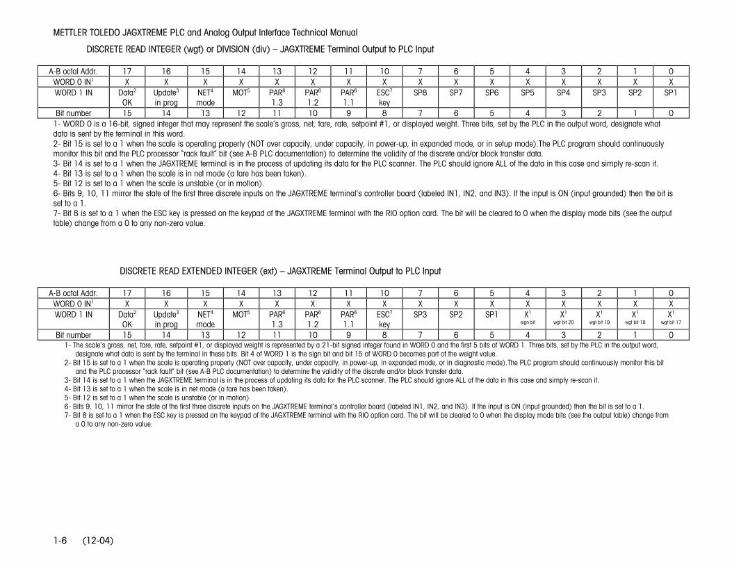
DISCRETE READ INTEGER (wgt) or DIVISION (div) – JAGXTREME Terminal Output to PLC Input
A-B octal Addr. 17 16 15 14 13 12 11 10 7 6 5 4 3 2 1 0WORD 0 IN1 X X X X X X X X X X X X X X X XWORD 1 IN Data2
OK Update3 in prog
NET4 mode
MOT5 PAR6 1.3
PAR6 1.2
PAR6 1.1
ESC7
key SP8 SP7 SP6 SP5 SP4 SP3 SP2 SP1
Bit number 15 14 13 12 11 10 9 8 7 6 5 4 3 2 1 01- WORD 0 is a 16-bit, signed integer that may represent the scale’s gross, net, tare, rate, setpoint #1, or displayed weight. Three bits, set by the PLC in the output word, designate what data is sent by the terminal in this word. 2- Bit 15 is set to a 1 when the scale is operating properly (NOT over capacity, under capacity, in power-up, in expanded mode, or in setup mode).The PLC program should continuously monitor this bit and the PLC processor “rack fault” bit (see A-B PLC documentation) to determine the validity of the discrete and/or block transfer data. 3- Bit 14 is set to a 1 when the JAGXTREME terminal is in the process of updating its data for the PLC scanner. The PLC should ignore ALL of the data in this case and simply re-scan it. 4- Bit 13 is set to a 1 when the scale is in net mode (a tare has been taken). 5- Bit 12 is set to a 1 when the scale is unstable (or in motion). 6- Bits 9, 10, 11 mirror the state of the first three discrete inputs on the JAGXTREME terminal’s controller board (labeled IN1, IN2, and IN3). If the input is ON (input grounded) then the bit is set to a 1. 7- Bit 8 is set to a 1 when the ESC key is pressed on the keypad of the JAGXTREME terminal with the RIO option card. The bit will be cleared to 0 when the display mode bits (see the output table) change from a 0 to any non-zero value.
DISCRETE READ EXTENDED INTEGER (ext) – JAGXTREME Terminal Output to PLC Input
A-B octal Addr. 17 16 15 14 13 12 11 10 7 6 5 4 3 2 1 0WORD 0 IN1 X X X X X X X X X X X X X X X XWORD 1 IN Data2
OK Update3 in prog
NET4 mode
MOT5 PAR6 1.3
PAR6 1.2
PAR6 1.1
ESC7
key SP3 SP2 SP1 X1
sign bitX1
wgt bit 20X1
wgt bit 19X1
wgt bit 18X1
wgt bit 17
Bit number 15 14 13 12 11 10 9 8 7 6 5 4 3 2 1 01- The scale’s gross, net, tare, rate, setpoint #1, or displayed weight is represented by a 21-bit signed integer found in WORD 0 and the first 5 bits of WORD 1. Three bits, set by the PLC in the output word,
designate what data is sent by the terminal in these bits. Bit 4 of WORD 1 is the sign bit and bit 15 of WORD 0 becomes part of the weight value. 2- Bit 15 is set to a 1 when the scale is operating properly (NOT over capacity, under capacity, in power-up, in expanded mode, or in diagnostic mode).The PLC program should continuously monitor this bit
and the PLC processor “rack fault” bit (see A-B PLC documentation) to determine the validity of the discrete and/or block transfer data. 3- Bit 14 is set to a 1 when the JAGXTREME terminal is in the process of updating its data for the PLC scanner. The PLC should ignore ALL of the data in this case and simply re-scan it. 4- Bit 13 is set to a 1 when the scale is in net mode (a tare has been taken). 5- Bit 12 is set to a 1 when the scale is unstable (or in motion). 6- Bits 9, 10, 11 mirror the state of the first three discrete inputs on the JAGXTREME terminal’s controller board (labeled IN1, IN2, and IN3). If the input is ON (input grounded) then the bit is set to a 1. 7- Bit 8 is set to a 1 when the ESC key is pressed on the keypad of the JAGXTREME terminal with the RIO option card. The bit will be cleared to 0 when the display mode bits (see the output table) change from
a 0 to any non-zero value.
(12-04) 1-6
Chapter 1: Allen-Bradley RIO Option Card Data Definition
(12-04) 1-7
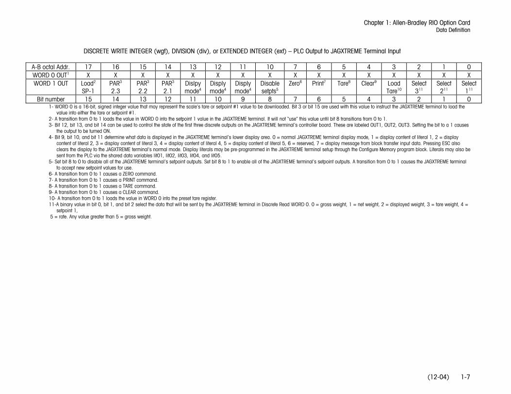
DISCRETE WRITE INTEGER (wgt), DIVISION (div), or EXTENDED INTEGER (ext) – PLC Output to JAGXTREME Terminal Input
A-B octal Addr. 17 16 15 14 13 12 11 10 7 6 5 4 3 2 1 0WORD 0 OUT1 X X X X X X X X X X X X X X X XWORD 1 OUT Load2
SP-1 PAR3 2.3
PAR3
2.2 PAR3
2.1 Dislpy mode4
Disply mode4
Disply mode4
Disable setpts5
Zero6 Print7 Tare8 Clear9 Load Tare10
Select 311
Select 211
Select 111
Bit number 15 14 13 12 11 10 9 8 7 6 5 4 3 2 1 01- WORD 0 is a 16-bit, signed integer value that may represent the scale’s tare or setpoint #1 value to be downloaded. Bit 3 or bit 15 are used with this value to instruct the JAGXTREME terminal to load the
value into either the tare or setpoint #1. 2- A transition from 0 to 1 loads the value in WORD 0 into the setpoint 1 value in the JAGXTREME terminal. It will not “use” this value until bit 8 transitions from 0 to 1. 3- Bit 12, bit 13, and bit 14 can be used to control the state of the first three discrete outputs on the JAGXTREME terminal’s controller board. These are labeled OUT1, OUT2, OUT3. Setting the bit to a 1 causes
the output to be turned ON. 4- Bit 9, bit 10, and bit 11 determine what data is displayed in the JAGXTREME terminal’s lower display area. 0 = normal JAGXTREME terminal display mode, 1 = display content of literal 1, 2 = display
content of literal 2, 3 = display content of literal 3, 4 = display content of literal 4, 5 = display content of literal 5, 6 = reserved, 7 = display message from block transfer input data. Pressing ESC also clears the display to the JAGXTREME terminal’s normal mode. Display literals may be pre-programmed in the JAGXTREME terminal setup through the Configure Memory program block. Literals may also be sent from the PLC via the shared data variables lit01, lit02, lit03, lit04, and lit05.
5- Set bit 8 to 0 to disable all of the JAGXTREME terminal’s setpoint outputs. Set bit 8 to 1 to enable all of the JAGXTREME terminal’s setpoint outputs. A transition from 0 to 1 causes the JAGXTREME terminal to accept new setpoint values for use.
6- A transition from 0 to 1 causes a ZERO command. 7- A transition from 0 to 1 causes a PRINT command. 8- A transition from 0 to 1 causes a TARE command. 9- A transition from 0 to 1 causes a CLEAR command. 10- A transition from 0 to 1 loads the value in WORD 0 into the preset tare register. 11-A binary value in bit 0, bit 1, and bit 2 select the data that will be sent by the JAGXTREME terminal in Discrete Read WORD 0. 0 = gross weight, 1 = net weight, 2 = displayed weight, 3 = tare weight, 4 =
setpoint 1, 5 = rate. Any value greater than 5 = gross weight.
METTLER TOLEDO JAGXTREME PLC and Analog Output Interface Technical Manual
1-8
Floating Point
(12-04)
Operational Overview
The terminal can send a rotation of up to nine different real-time values for each scale. The PLC sends commands to the terminal to add a value to the rotation. Once the rotation is established, the PLC must instruct the terminal to begin its rotation automatically, or the PLC may control the pace of rotation by instructing the terminal to advance to the next value. If the terminal is asked to automatically alternate its output data, it will switch to the next value in its rotation at the next A/D update. (The A/D update rate depends on the scale type. An analog scale has an update rate of 17 Hz or 58 milliseconds.)
The terminal has two types of values that it can report to the PLC: real-time and static. When the PLC requests a real-time value, the terminal acknowledges the command from the PLC once but sends and updates the value at every A/D update. If the PLC requests a static value, the terminal acknowledges the command from the PLC once and updates the value once. The terminal will continue to send this value until it receives a new command from the PLC. Gross weight, net weight, and rate are examples of real-time data. Tare weight, setpoint cutoff, dribble, and tolerance values are examples of static data.
The JAGXTREME terminal uses integer commands from the PLC to select the floating point weight output data. The terminal recognizes a command when it sees a new value in the scale’s command word. If the command has an associated floating point value (for example: loading a setpoint value), it must be loaded into the floating point value words before the command is issued. Once the terminal recognizes a command, it acknowledges the command by setting a new value in the command acknowledge bits of the scale’s command response word. It also tells the PLC what floating point value is being sent (via the floating point input indicator bits of the command response word). The PLC waits until it receives the command acknowledgment from the terminal before sending another command.
The following charts provide detailed information on the floating-point data format. Read data refers to the PLC’s input data and write data refers to the PLC’s output data.
The PLC may control the rotation by sending alternate report next field commands (1 and 2). When the PLC changes to the next command, the terminal switches to the next value in the rotation. The terminal stores the rotation in its shared data so the rotation does not have to be re-initialized after each power cycle. When the PLC does not set up an input rotation, the default input rotation consists of gross weight only. See the floating-point rotation examples for additional information.
Chapter 1: Allen-Bradley RIO Option Card Data Definition
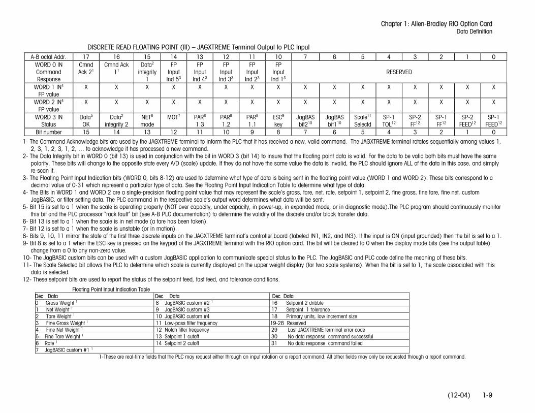
DISCRETE READ FLOATING POINT (flt) – JAGXTREME Terminal Output to PLC Input
A-B octal Addr. 17 16 15 14 13 12 11 10 7 6 5 4 3 2 1 0WORD 0 IN Command Response
Cmnd Ack 21
Cmnd Ack 11
Data2 integrity
1
FP Input Ind 53
FP Input Ind 43
FP Input Ind 33
FP Input Ind 23
FP Input Ind 13
RESERVED
WORD 1 IN4
FP value X X X X X X X X X X X X X X X X
WORD 2 IN4
FP value X X X X X X X X X X X X X X X X
WORD 3 IN Status
Data5 OK
Data2 integrity 2
NET6 mode
MOT7 PAR8 1.3
PAR8 1.2
PAR8 1.1
ESC9
key JagBAS bit210
JagBAS bit110
Scale11
Selectd SP-1 TOL12
SP-2 FF12
SP-1 FF12
SP-2 FEED12
SP-1 FEED12
Bit number 15 14 13 12 11 10 9 8 7 6 5 4 3 2 1 0
1- The Command Acknowledge bits are used by the JAGXTREME terminal to inform the PLC that it has received a new, valid command. The JAGXTREME terminal rotates sequentially among values 1, 2, 3, 1, 2, 3, 1, 2, … to acknowledge it has processed a new command.
2- The Data Integrity bit in WORD 0 (bit 13) is used in conjunction with the bit in WORD 3 (bit 14) to insure that the floating point data is valid. For the data to be valid both bits must have the same polarity. These bits will change to the opposite state every A/D (scale) update. If they do not have the same value the data is invalid, the PLC should ignore ALL of the data in this case, and simply re-scan it.
3- The Floating Point Input Indication bits (WORD 0, bits 8-12) are used to determine what type of data is being sent in the floating point value (WORD 1 and WORD 2). These bits correspond to a decimal value of 0-31 which represent a particular type of data. See the Floating Point Input Indication Table to determine what type of data.
4- The Bits in WORD 1 and WORD 2 are a single-precision floating point value that may represent the scale’s gross, tare, net, rate, setpoint 1, setpoint 2, fine gross, fine tare, fine net, custom JagBASIC, or filter setting data. The PLC command in the respective scale’s output word determines what data will be sent.
5- Bit 15 is set to a 1 when the scale is operating properly (NOT over capacity, under capacity, in power-up, in expanded mode, or in diagnostic mode).The PLC program should continuously monitor this bit and the PLC processor “rack fault” bit (see A-B PLC documentation) to determine the validity of the discrete and/or block transfer data.
6- Bit 13 is set to a 1 when the scale is in net mode (a tare has been taken). 7- Bit 12 is set to a 1 when the scale is unstable (or in motion). 8- Bits 9, 10, 11 mirror the state of the first three discrete inputs on the JAGXTREME terminal’s controller board (labeled IN1, IN2, and IN3). If the input is ON (input grounded) then the bit is set to a 1. 9- Bit 8 is set to a 1 when the ESC key is pressed on the keypad of the JAGXTREME terminal with the RIO option card. The bit will be cleared to 0 when the display mode bits (see the output table)
change from a 0 to any non-zero value. 10- The JagBASIC custom bits can be used with a custom JagBASIC application to communicate special status to the PLC. The JagBASIC and PLC code define the meaning of these bits. 11- The Scale Selected bit allows the PLC to determine which scale is currently displayed on the upper weight display (for two scale systems). When the bit is set to 1, the scale associated with this
data is selected. 12- These setpoint bits are used to report the status of the setpoint feed, fast feed, and tolerance conditions.
Floating Point Input Indication Table Dec Data Dec Data Dec Data 0 Gross Weight 1 8 JagBASIC custom #2 1 16 Setpoint 2 dribble 1 Net Weight 1 9 JagBASIC custom #3 17 Setpoint 1 tolerance 2 Tare Weight 1 10 JagBASIC custom #4 18 Primary units, low increment size 3 Fine Gross Weight 1 11 Low-pass filter frequency 19-28 Reserved 4 Fine Net Weight 1 12 Notch filter frequency 29 Last JAGXTREME terminal error code 5 Fine Tare Weight 1 13 Setpoint 1 cutoff 30 No data response command successful 6 Rate 1 14 Setpoint 2 cutoff 31 No data response command failed 7 JagBASIC custom #1 1
1-These are real-time fields that the PLC may request either through an input rotation or a report command. All other fields may only be requested through a report command.
(12-04) 1-9
METTLER TOLEDO JAGXTREME PLC and Analog Output Interface Technical Manual
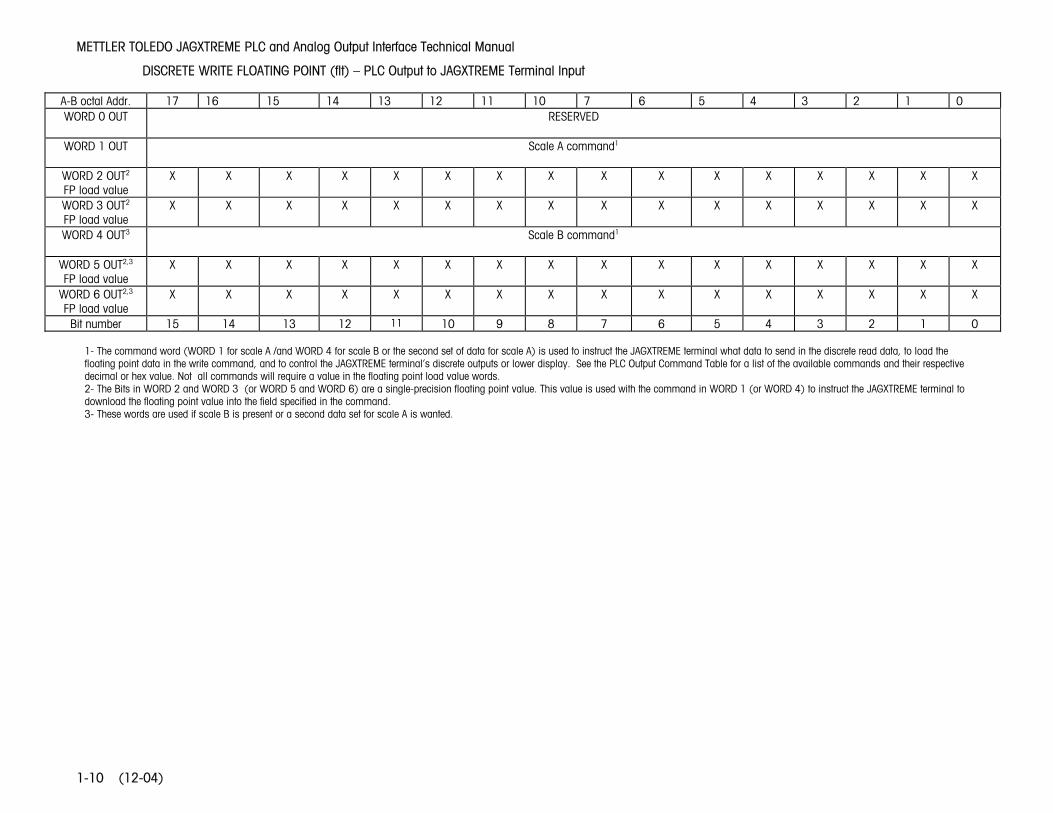
DISCRETE WRITE FLOATING POINT (flt) – PLC Output to JAGXTREME Terminal Input
A-B octal Addr. 17 16 15 14 13 12 11 10 7 6 5 4 3 2 1 0WORD 0 OUT RESERVED
WORD 1 OUT
Scale A command1
WORD 2 OUT2
FP load value X X X X X X X X X X X X X X X X
WORD 3 OUT2
FP load value X X X X X X X X X X X X X X X X
WORD 4 OUT3 Scale B command1
WORD 5 OUT2,3
FP load value X X X X X X X X X X X X X X X X
WORD 6 OUT2,3 FP load value
X X X X X X X X X X X X X X X X
Bit number 15 14 13 12 11 10 9 8 7 6 5 4 3 2 1 0
1- The command word (WORD 1 for scale A /and WORD 4 for scale B or the second set of data for scale A) is used to instruct the JAGXTREME terminal what data to send in the discrete read data, to load the floating point data in the write command, and to control the JAGXTREME terminal’s discrete outputs or lower display. See the PLC Output Command Table for a list of the available commands and their respective decimal or hex value. Not all commands will require a value in the floating point load value words. 2- The Bits in WORD 2 and WORD 3 (or WORD 5 and WORD 6) are a single-precision floating point value. This value is used with the command in WORD 1 (or WORD 4) to instruct the JAGXTREME terminal to download the floating point value into the field specified in the command. 3- These words are used if scale B is present or a second data set for scale A is wanted.
(12-04) 1-10
Chapter 1: Allen-Bradley RIO Option Card Data Definition
(12-04) 1-11
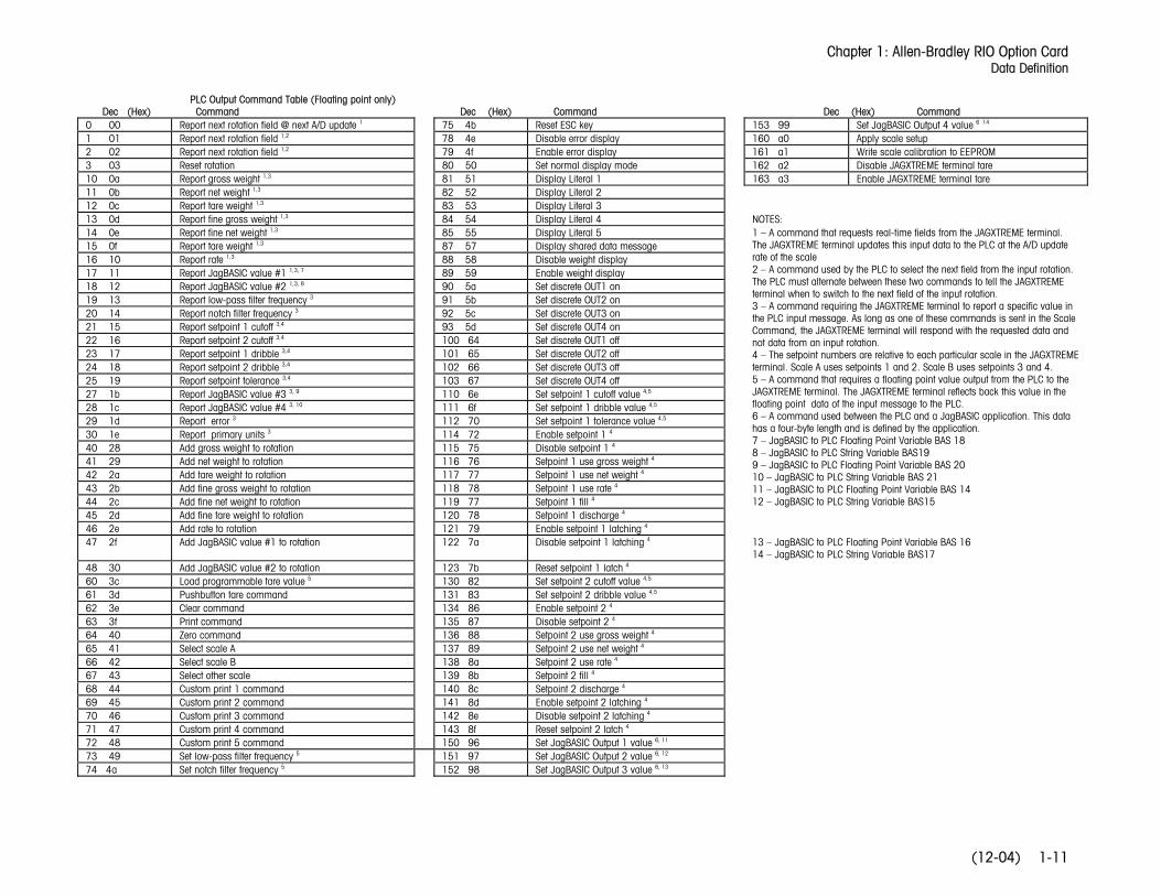
PLC Output Command Table (Floating point only) Dec (Hex) Command Dec (Hex) Command Dec (Hex) Command 0 00 Report next rotation field @ next A/D update 1 75 4b Reset ESC key 153 99 Set JagBASIC Output 4 value 6 14
1 01 Report next rotation field 1,2 78 4e Disable error display 160 a0 Apply scale setup 2 02 Report next rotation field 1,2 79 4f Enable error display 161 a1 Write scale calibration to EEPROM 3 03 Reset rotation 80 50 Set normal display mode 162 a2 Disable JAGXTREME terminal tare 10 0a Report gross weight 1,3 81 51 Display Literal 1 163 a3 Enable JAGXTREME terminal tare 11 0b Report net weight 1,3 82 52 Display Literal 2 12 0c Report tare weight 1,3 83 53 Display Literal 3 13 0d Report fine gross weight 1,3 84 54 Display Literal 4 NOTES: 14 0e Report fine net weight 1,3 85 55 Display Literal 5 15 0f Report tare weight 1,3 87 57 Display shared data message 16 10 Report rate 1,3 88 58 Disable weight display 17 11 Report JagBASIC value #1 1,3, 7 89 59 Enable weight display 18 12 Report JagBASIC value #2 1,3, 8 90 5a Set discrete OUT1 on 19 13 Report low-pass filter frequency 3 91 5b Set discrete OUT2 on 20 14 Report notch filter frequency 3 92 5c Set discrete OUT3 on 21 15 Report setpoint 1 cutoff 3,4 93 5d Set discrete OUT4 on 22 16 Report setpoint 2 cutoff 3,4 100 64 Set discrete OUT1 off 23 17 Report setpoint 1 dribble 3,4 101 65 Set discrete OUT2 off 24 18 Report setpoint 2 dribble 3,4 102 66 Set discrete OUT3 off 25 19 Report setpoint tolerance 3,4 103 67 Set discrete OUT4 off 27 1b Report JagBASIC value #3 3, 9 110 6e Set setpoint 1 cutoff value 4,5 28 1c Report JagBASIC value #4 3, 10 111 6f Set setpoint 1 dribble value 4,5 29 1d Report error 3 112 70 Set setpoint 1 tolerance value 4,5 30 1e Report primary units 3 114 72 Enable setpoint 1 4 40 28 Add gross weight to rotation 115 75 Disable setpoint 1 4 41 29 Add net weight to rotation 116 76 Setpoint 1 use gross weight 4 42 2a Add tare weight to rotation 117 77 Setpoint 1 use net weight 4 43 2b Add fine gross weight to rotation 118 78 Setpoint 1 use rate 4 44 2c Add fine net weight to rotation 119 77 Setpoint 1 fill 4 45 2d Add fine tare weight to rotation 120 78 Setpoint 1 discharge 4 46 2e Add rate to rotation 121 79 Enable setpoint 1 latching 4
1 – A command that requests real-time fields from the JAGXTREME terminal. The JAGXTREME terminal updates this input data to the PLC at the A/D update rate of the scale 2 – A command used by the PLC to select the next field from the input rotation. The PLC must alternate between these two commands to tell the JAGXTREME terminal when to switch to the next field of the input rotation. 3 – A command requiring the JAGXTREME terminal to report a specific value in the PLC input message. As long as one of these commands is sent in the Scale Command, the JAGXTREME terminal will respond with the requested data and not data from an input rotation. 4 – The setpoint numbers are relative to each particular scale in the JAGXTREME terminal. Scale A uses setpoints 1 and 2. Scale B uses setpoints 3 and 4. 5 – A command that requires a floating point value output from the PLC to the JAGXTREME terminal. The JAGXTREME terminal reflects back this value in the floating point data of the input message to the PLC. 6 – A command used between the PLC and a JagBASIC application. This data has a four-byte length and is defined by the application. 7 – JagBASIC to PLC Floating Point Variable BAS 18 8 – JagBASIC to PLC String Variable BAS19 9 – JagBASIC to PLC Floating Point Variable BAS 20 10 – JagBASIC to PLC String Variable BAS 21 11 – JagBASIC to PLC Floating Point Variable BAS 14 12 – JagBASIC to PLC String Variable BAS15
47 2f Add JagBASIC value #1 to rotation 122 7a Disable setpoint 1 latching 4 13 – JagBASIC to PLC Floating Point Variable BAS 16 14 – JagBASIC to PLC String Variable BAS17
48 30 Add JagBASIC value #2 to rotation 123 7b Reset setpoint 1 latch 4 60 3c Load programmable tare value 5 130 82 Set setpoint 2 cutoff value 4,5 61 3d Pushbutton tare command 131 83 Set setpoint 2 dribble value 4,5 62 3e Clear command 134 86 Enable setpoint 2 4 63 3f Print command 135 87 Disable setpoint 2 4 64 40 Zero command 136 88 Setpoint 2 use gross weight 4 65 41 Select scale A 137 89 Setpoint 2 use net weight 4 66 42 Select scale B 138 8a Setpoint 2 use rate 4 67 43 Select other scale 139 8b Setpoint 2 fill 4 68 44 Custom print 1 command 140 8c Setpoint 2 discharge 4 69 45 Custom print 2 command 141 8d Enable setpoint 2 latching 4 70 46 Custom print 3 command 142 8e Disable setpoint 2 latching 4 71 47 Custom print 4 command 143 8f Reset setpoint 2 latch 4 72 48 Custom print 5 command 150 96 Set JagBASIC Output 1 value 6, 11 73 49 Set low-pass filter frequency 5 151 97 Set JagBASIC Output 2 value 6, 12 74 4a Set notch filter frequency 5 152 98 Set JagBASIC Output 3 value 6, 13
METTLER TOLEDO Jaguar/Jagxtreme PLC and Analog Interface Technical Manual
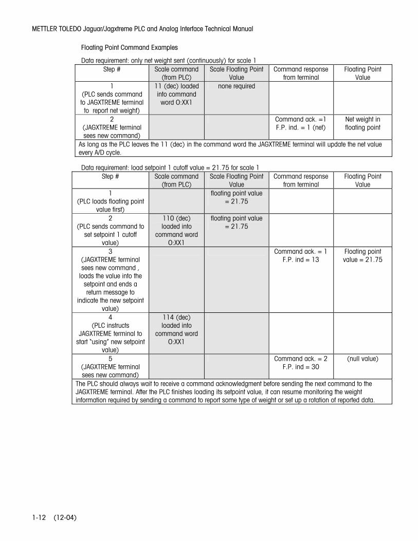
Floating Point Command Examples
Data requirement: only net weight sent (continuously) for scale 1 Step # Scale command
(from PLC) Scale Floating Point
Value Command response
from terminal Floating Point
Value 1
(PLC sends command to JAGXTREME terminal to report net weight)
11 (dec) loaded into command word O:XX1
none required
2 (JAGXTREME terminal sees new command)
Command ack. =1 F.P. ind. = 1 (net)
Net weight in floating point
As long as the PLC leaves the 11 (dec) in the command word the JAGXTREME terminal will update the net value every A/D cycle. Data requirement: load setpoint 1 cutoff value = 21.75 for scale 1
Step # Scale command (from PLC)
Scale Floating Point Value
Command response from terminal
Floating Point Value
1 (PLC loads floating point
value first)
floating point value = 21.75
2 (PLC sends command to
set setpoint 1 cutoff value)
110 (dec) loaded into
command word O:XX1
floating point value = 21.75
3 (JAGXTREME terminal sees new command ,
loads the value into the setpoint and ends a return message to
indicate the new setpoint value)
Command ack. = 1 F.P. ind = 13
Floating point value = 21.75
4 (PLC instructs
JAGXTREME terminal to start “using” new setpoint
value)
114 (dec) loaded into
command word O:XX1
5 (JAGXTREME terminal sees new command)
Command ack. = 2 F.P. ind = 30
(null value)
The PLC should always wait to receive a command acknowledgment before sending the next command to the JAGXTREME terminal. After the PLC finishes loading its setpoint value, it can resume monitoring the weight information required by sending a command to report some type of weight or set up a rotation of reported data.
(12-04) 1-12
Chapter 1: Allen-Bradley RIO Option Card Data Definition
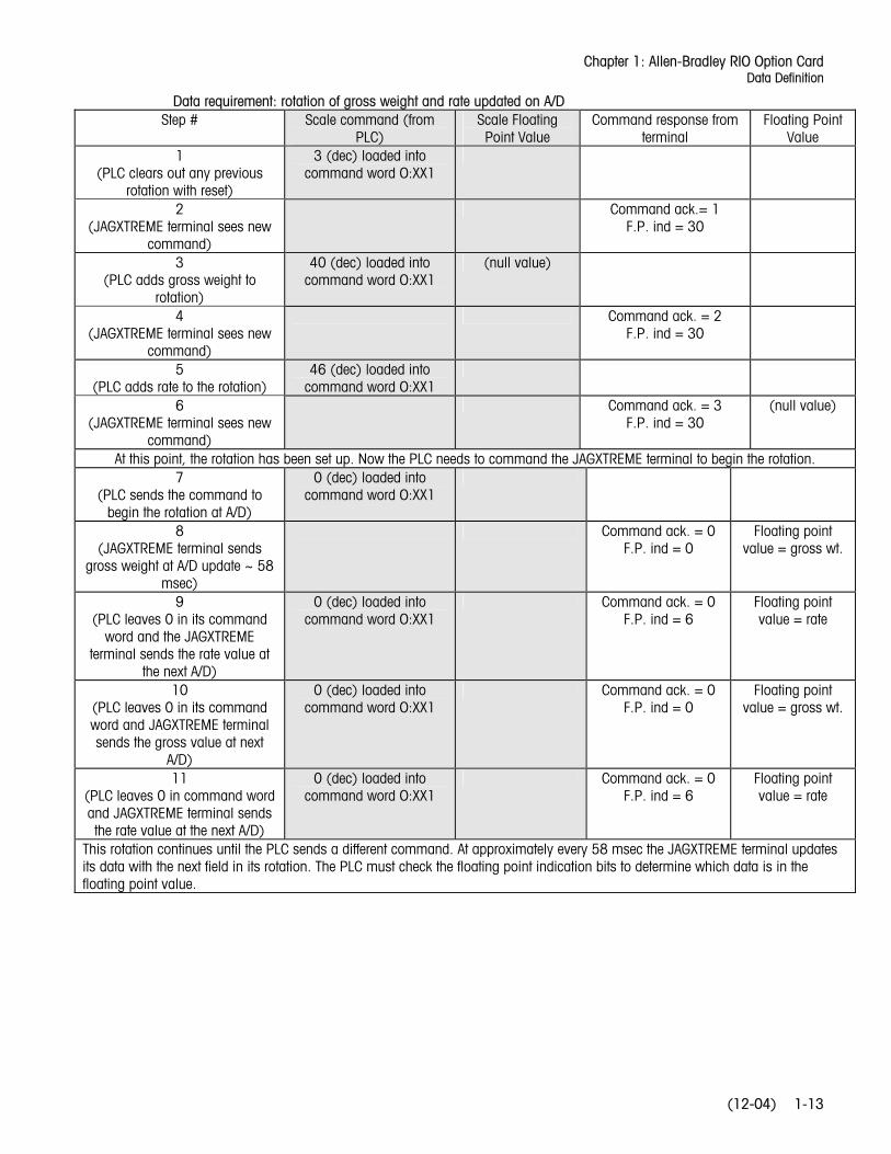
Data requirement: rotation of gross weight and rate updated on A/D Step # Scale command (from
PLC) Scale Floating Point Value
Command response from terminal
Floating Point Value
1 (PLC clears out any previous
rotation with reset)
3 (dec) loaded into command word O:XX1
2 (JAGXTREME terminal sees new
command)
Command ack.= 1 F.P. ind = 30
3 (PLC adds gross weight to
rotation)
40 (dec) loaded into command word O:XX1
(null value)
4 (JAGXTREME terminal sees new
command)
Command ack. = 2 F.P. ind = 30
5 (PLC adds rate to the rotation)
46 (dec) loaded into command word O:XX1
6 (JAGXTREME terminal sees new
command)
Command ack. = 3 F.P. ind = 30
(null value)
At this point, the rotation has been set up. Now the PLC needs to command the JAGXTREME terminal to begin the rotation. 7
(PLC sends the command to begin the rotation at A/D)
0 (dec) loaded into command word O:XX1
8 (JAGXTREME terminal sends
gross weight at A/D update ~ 58 msec)
Command ack. = 0 F.P. ind = 0
Floating point value = gross wt.
9 (PLC leaves 0 in its command
word and the JAGXTREME terminal sends the rate value at
the next A/D)
0 (dec) loaded into command word O:XX1
Command ack. = 0 F.P. ind = 6
Floating point value = rate
10 (PLC leaves 0 in its command word and JAGXTREME terminal sends the gross value at next
A/D)
0 (dec) loaded into command word O:XX1
Command ack. = 0 F.P. ind = 0
Floating point value = gross wt.
11 (PLC leaves 0 in command word and JAGXTREME terminal sends the rate value at the next A/D)
0 (dec) loaded into command word O:XX1
Command ack. = 0 F.P. ind = 6
Floating point value = rate
This rotation continues until the PLC sends a different command. At approximately every 58 msec the JAGXTREME terminal updates its data with the next field in its rotation. The PLC must check the floating point indication bits to determine which data is in the floating point value.
(12-04) 1-13
METTLER TOLEDO Jaguar/Jagxtreme PLC and Analog Interface Technical Manual
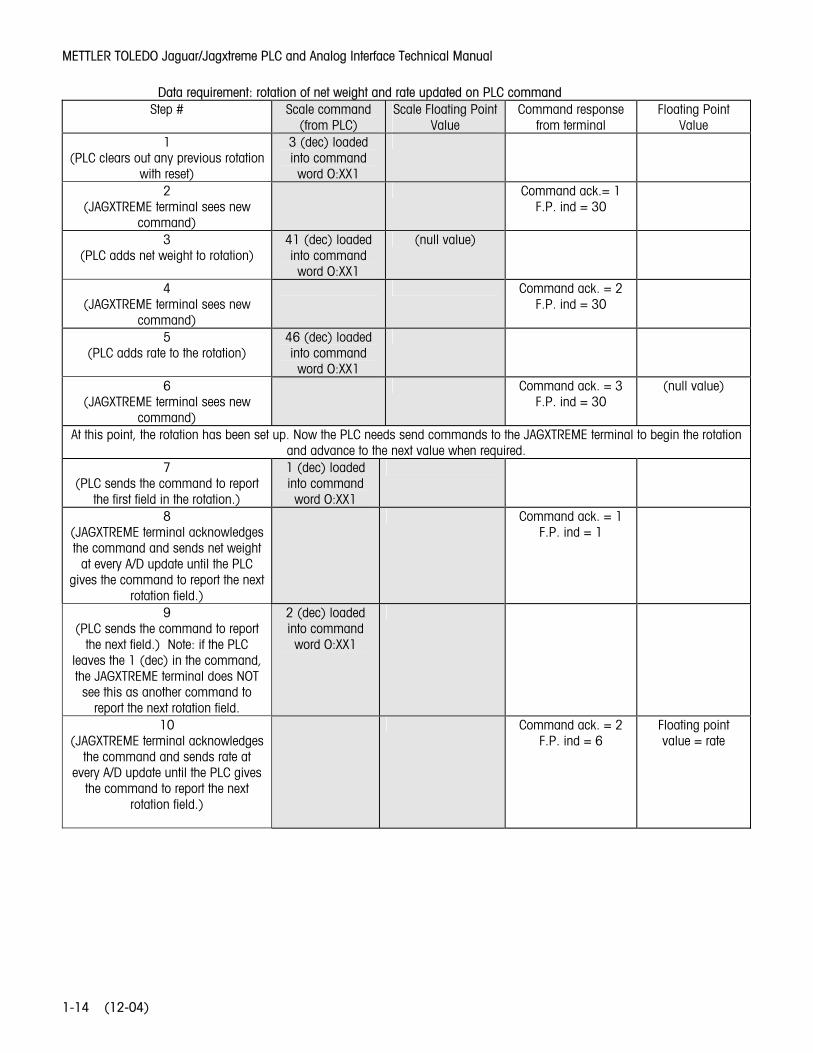
Data requirement: rotation of net weight and rate updated on PLC command Step # Scale command
(from PLC) Scale Floating Point
Value Command response
from terminal Floating Point
Value 1
(PLC clears out any previous rotation with reset)
3 (dec) loaded into command word O:XX1
2 (JAGXTREME terminal sees new
command)
Command ack.= 1 F.P. ind = 30
3 (PLC adds net weight to rotation)
41 (dec) loaded into command word O:XX1
(null value)
4 (JAGXTREME terminal sees new
command)
Command ack. = 2 F.P. ind = 30
5 (PLC adds rate to the rotation)
46 (dec) loaded into command word O:XX1
6 (JAGXTREME terminal sees new
command)
Command ack. = 3 F.P. ind = 30
(null value)
At this point, the rotation has been set up. Now the PLC needs send commands to the JAGXTREME terminal to begin the rotation and advance to the next value when required.
7 (PLC sends the command to report
the first field in the rotation.)
1 (dec) loaded into command word O:XX1
8 (JAGXTREME terminal acknowledges the command and sends net weight
at every A/D update until the PLC gives the command to report the next
rotation field.)
Command ack. = 1 F.P. ind = 1
9 (PLC sends the command to report
the next field.) Note: if the PLC leaves the 1 (dec) in the command, the JAGXTREME terminal does NOT see this as another command to
report the next rotation field.
2 (dec) loaded into command word O:XX1
10 (JAGXTREME terminal acknowledges
the command and sends rate at every A/D update until the PLC gives
the command to report the next rotation field.)
Command ack. = 2 F.P. ind = 6
Floating point value = rate
(12-04) 1-14
Chapter 1: Allen-Bradley RIO Option Card Data Definition
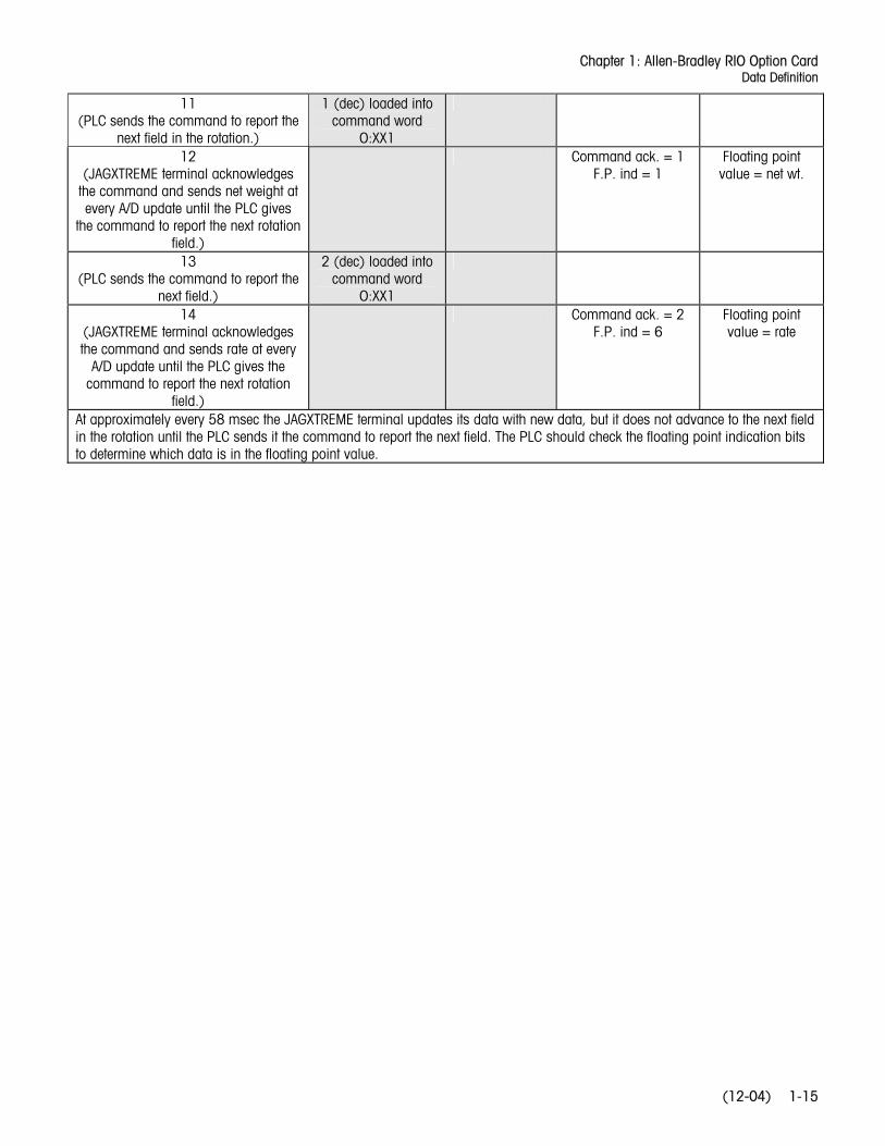
11 (PLC sends the command to report the
next field in the rotation.)
1 (dec) loaded into command word
O:XX1
12 (JAGXTREME terminal acknowledges
the command and sends net weight at every A/D update until the PLC gives
the command to report the next rotation field.)
Command ack. = 1 F.P. ind = 1
Floating point value = net wt.
13 (PLC sends the command to report the
next field.)
2 (dec) loaded into command word
O:XX1
14 (JAGXTREME terminal acknowledges the command and sends rate at every
A/D update until the PLC gives the command to report the next rotation
field.)
Command ack. = 2 F.P. ind = 6
Floating point value = rate
At approximately every 58 msec the JAGXTREME terminal updates its data with new data, but it does not advance to the next field in the rotation until the PLC sends it the command to report the next field. The PLC should check the floating point indication bits to determine which data is in the floating point value.
(12-04) 1-15
METTLER TOLEDO Jaguar/Jagxtreme PLC and Analog Interface Technical Manual
Floating Point Data Format and Compatibility In Floating Point Message mode, the PLC and terminal exchange weight, rate, setpoint, and tare data in single-precision floating point format. The IEEE Standard for Binary Floating-Point Arithmetic, ANSI/IEEE Standard 754-1985, specifies the format for single-precision floating point numbers. It is a 32-bit number that has a 1-bit sign, an 8-bit signed exponent, and a 23-bit mantissa. The 8-bit signed exponent provides scaling of weight and rate data. The 23-bit mantissa allows representation of 8 million unique counts.
Although the single-precision floating point number provides greater numerical precision and flexibility than integer weight representations, it has limitations. The weight representation may not be exact, particularly for the extended-resolution weight fields for high-precision bases.
Some Allen-Bradley PLCs require special integrity checking to communicate floating point numbers across the Remote I/O link. The Allen-Bradley PLC-5 and KTX Scanner Card programs must check two data integrity bits to verify the integrity of the floating point data it reads from the terminal. Allen-Bradley SLC programs always read valid floating-point data from JAGXTREME terminals and do not have to make special checks to guarantee the validity of the floating-point data. The Allen-Bradley PLC-3 and PLC-5/250 cannot support terminals in floating point mode as they cannot guarantee the integrity of the floating-point data.
There are two data integrity bits that the terminal uses to maintain data integrity when communicating with the Allen-Bradley PLC-5 Remote I/O Scanner or KTX Scanner Card. One bit is in the beginning byte of the data; the second is in the ending byte of the data for a scale slot. The PLC program must verify that both data integrity bits have the same polarity for the data in the scale slot to be valid. There is a possibility that the PLC program will see several consecutive invalid reads when the terminal is freely sending weigh updates to the PLC-5 program detects this condition, it should send a new command to the terminal.
The Allen-Bradley SLC PLC programs do not have to make special checks to guarantee the validity of the floating-point data.
Shared Data Mode The Shared Data mode PLC communications is not available in Allen-Bradley PLCs. Block Transfer communications is used instead.
Block Transfer Block Transfer mode is much less efficient than the discrete data modes, which are optimized for real time communications of weight and status data. Block Transfer mode accesses the terminal’s “Shared Data” directory structure each time a data item is accessed. By contrast, the weight-synchronous mode communications has a direct interface to a limited number of real time terminal data fields.
Note: Do not use Block Transfer mode for real-time communications.
Block Transfer Data Block transfer allows the JAGXTREME terminal and PLC to exchange many types of data in blocks of up to 128 bytes. It also enables the PLC to write messages directly to the terminal's lower display area.
Block transfer works concurrently with discrete data. Discrete mode communicates continuously in the background and a block transfer occurs only when the PLC program executes a block transfer read or write instruction. Data transfer is controlled by the PLC.
(12-04) 1-16
Chapter 1: Allen-Bradley RIO Option Card Data Definition
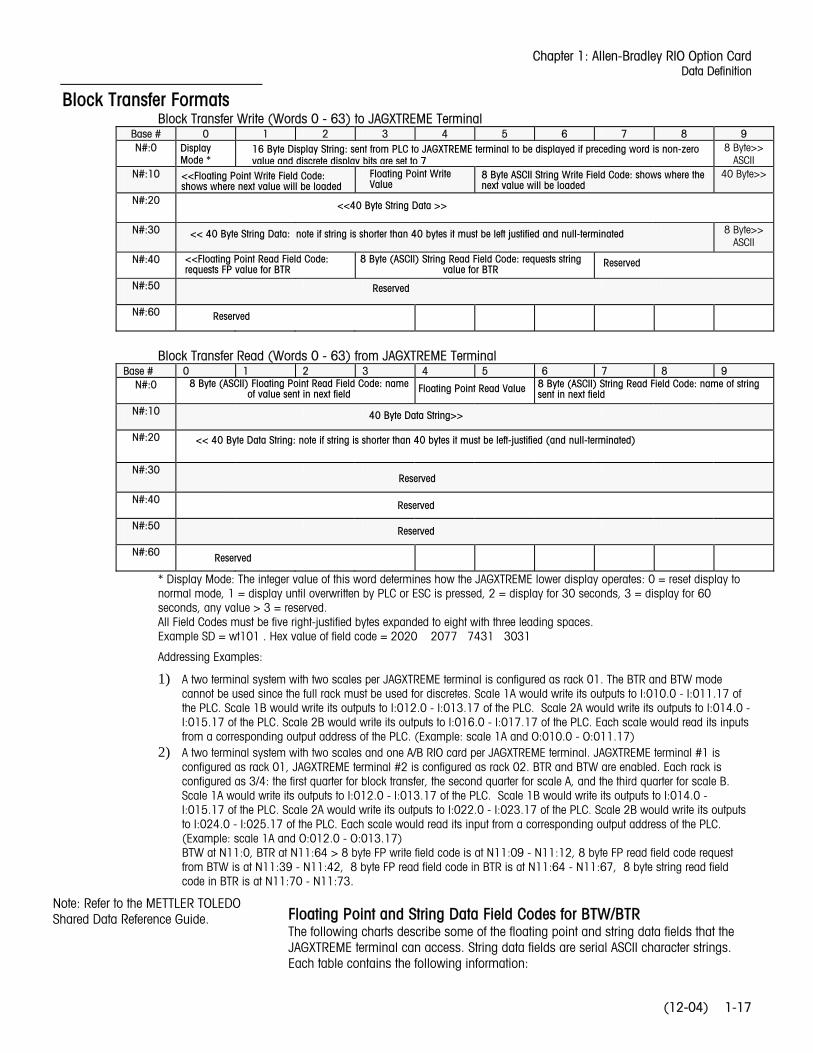
Block Transfer Formats Block Transfer Write (Words 0 - 63) to JAGXTREME Terminal
Base # 0 1 2 3 4 5 6 7 8 9 N#:0
8 Byte>>
ASCII N#:10
40 Byte>>
N#:20
N#:30
8 Byte>> ASCII
N#:40
N#:50
N#:60
Display Mode *
16 Byte Display String: sent from PLC to JAGXTREME terminal to be displayed if preceding word is non-zero value and discrete display bits are set to 7
Floating Point Write Value
<<Floating Point Write Field Code: shows where next value will be loaded
8 Byte ASCII String Write Field Code: shows where the next value will be loaded
<<40 Byte String Data >>
<< 40 Byte String Data: note if string is shorter than 40 bytes it must be left justified and null-terminated
<<Floating Point Read Field Code: requests FP value for BTR
8 Byte (ASCII) String Read Field Code: requests string value for BTR
Reserved
Reserved
Reserved
Block Transfer Read (Words 0 - 63) from JAGXTREME Terminal
Base # 0 1 2 3 4 5 6 7 8 9 N#:0
N#:10
N#:20
N#:30
N#:40
N#:50
N#:60
8 Byte (ASCII) Floating Point Read Field Code: name of value sent in next field
8 Byte (ASCII) String Read Field Code: name of string sent in next field Floating Point Read Value
40 Byte Data String>>
<< 40 Byte Data String: note if string is shorter than 40 bytes it must be left-justified (and null-terminated)
Reserved
Reserved
Reserved
Reserved
* Display Mode: The integer value of this word determines how the JAGXTREME lower display operates: 0 = reset display to normal mode, 1 = display until overwritten by PLC or ESC is pressed, 2 = display for 30 seconds, 3 = display for 60 seconds, any value > 3 = reserved. All Field Codes must be five right-justified bytes expanded to eight with three leading spaces. Example SD = wt101 . Hex value of field code = 2020 2077 7431 3031
Addressing Examples:
1) A two terminal system with two scales per JAGXTREME terminal is configured as rack 01. The BTR and BTW mode cannot be used since the full rack must be used for discretes. Scale 1A would write its outputs to I:010.0 - I:011.17 of the PLC. Scale 1B would write its outputs to I:012.0 - I:013.17 of the PLC. Scale 2A would write its outputs to I:014.0 - I:015.17 of the PLC. Scale 2B would write its outputs to I:016.0 - I:017.17 of the PLC. Each scale would read its inputs from a corresponding output address of the PLC. (Example: scale 1A and O:010.0 - O:011.17)
2) A two terminal system with two scales and one A/B RIO card per JAGXTREME terminal. JAGXTREME terminal #1 is configured as rack 01, JAGXTREME terminal #2 is configured as rack 02. BTR and BTW are enabled. Each rack is configured as 3/4: the first quarter for block transfer, the second quarter for scale A, and the third quarter for scale B. Scale 1A would write its outputs to I:012.0 - I:013.17 of the PLC. Scale 1B would write its outputs to I:014.0 - I:015.17 of the PLC. Scale 2A would write its outputs to I:022.0 - I:023.17 of the PLC. Scale 2B would write its outputs to I:024.0 - I:025.17 of the PLC. Each scale would read its input from a corresponding output address of the PLC. (Example: scale 1A and O:012.0 - O:013.17) BTW at N11:0, BTR at N11:64 > 8 byte FP write field code is at N11:09 - N11:12, 8 byte FP read field code request from BTW is at N11:39 - N11:42, 8 byte FP read field code in BTR is at N11:64 - N11:67, 8 byte string read field code in BTR is at N11:70 - N11:73.
Floating Point and String Data Field Codes for BTW/BTR The following charts describe some of the floating point and string data fields that the JAGXTREME terminal can access. String data fields are serial ASCII character strings. Each table contains the following information:
Note: Refer to the METTLER TOLEDO Shared Data Reference Guide.
(12-04) 1-17
METTLER TOLEDO Jaguar/Jagxtreme PLC and Analog Interface Technical Manual
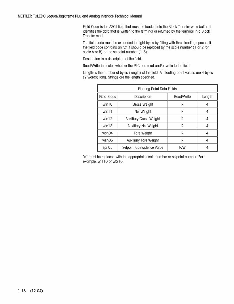
Field Code-is the ASCII field that must be loaded into the Block Transfer write buffer. It identifies the data that is written to the terminal or returned by the terminal in a Block Transfer read.
The field code must be expanded to eight bytes by filling with three leading spaces. If the field code contains an “n” it should be replaced by the scale number (1 or 2 for scale A or B) or the setpoint number (1-8).
Description-is a description of the field.
Read/Write-indicates whether the PLC can read and/or write to the field.
Length-is the number of bytes (length) of the field. All floating point values are 4 bytes (2 words) long. Strings are the length specified.
Floating Point Data Fields
Field Code Description Read/Write Length
wtn10 Gross Weight R 4
wtn11 Net Weight R 4
wtn12 Auxiliary Gross Weight R 4
wtn13 Auxiliary Net Weight R 4
wsn04 Tare Weight R 4
wsn05 Auxiliary Tare Weight R 4
spn05 Setpoint Coincidence Value R/W 4
“n” must be replaced with the appropriate scale number or setpoint number. For example, wt110 or wt210.
(12-04) 1-18
Chapter 1: Allen-Bradley RIO Option Card Data Definition
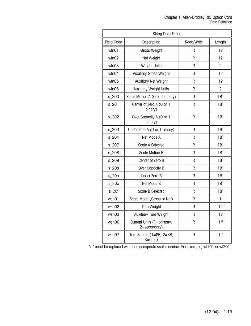
String Data Fields
Field Code Description Read/Write Length
wtn01 Gross Weight R 12
wtn02 Net Weight R 12
wtn03 Weight Units R 2
wtn04 Auxiliary Gross Weight R 12
wtn05 Auxiliary Net Weight R 12
wtn06 Auxiliary Weight Units R 2
s_200 Scale Motion A (0 or 1 binary) R 1B1
s_201 Center of Zero A (0 or 1 binary)
R 1B1
s_202 Over Capacity A (0 or 1 binary)
R 1B1
s_203 Under Zero A (0 or 1 binary) R 1B1
s_204 Net Mode A R 1B1
s_207 Scale A Selected R 1B1
s_208 Scale Motion B R 1B1
s_209 Center of Zero B R 1B1
s_20a Over Capacity B R 1B1
s_20b Under Zero B R 1B1
s_20c Net Mode B R 1B1
s_20f Scale B Selected R 1B1
wsn01 Scale Mode (Gross or Net) R 1
wsn02 Tare Weight R 12
wsn03 Auxiliary Tare Weight R 12
wsn06 Current Units (1=primary, 2=secondary)
R 1I3
wsn07 Tare Source (1=PB, 2=KB, 3=auto)
R 1I3
“n” must be replaced with the appropriate scale number. For example, wt101 or wt201.
(12-04) 1-19
METTLER TOLEDO Jaguar/Jagxtreme PLC and Analog Interface Technical Manual
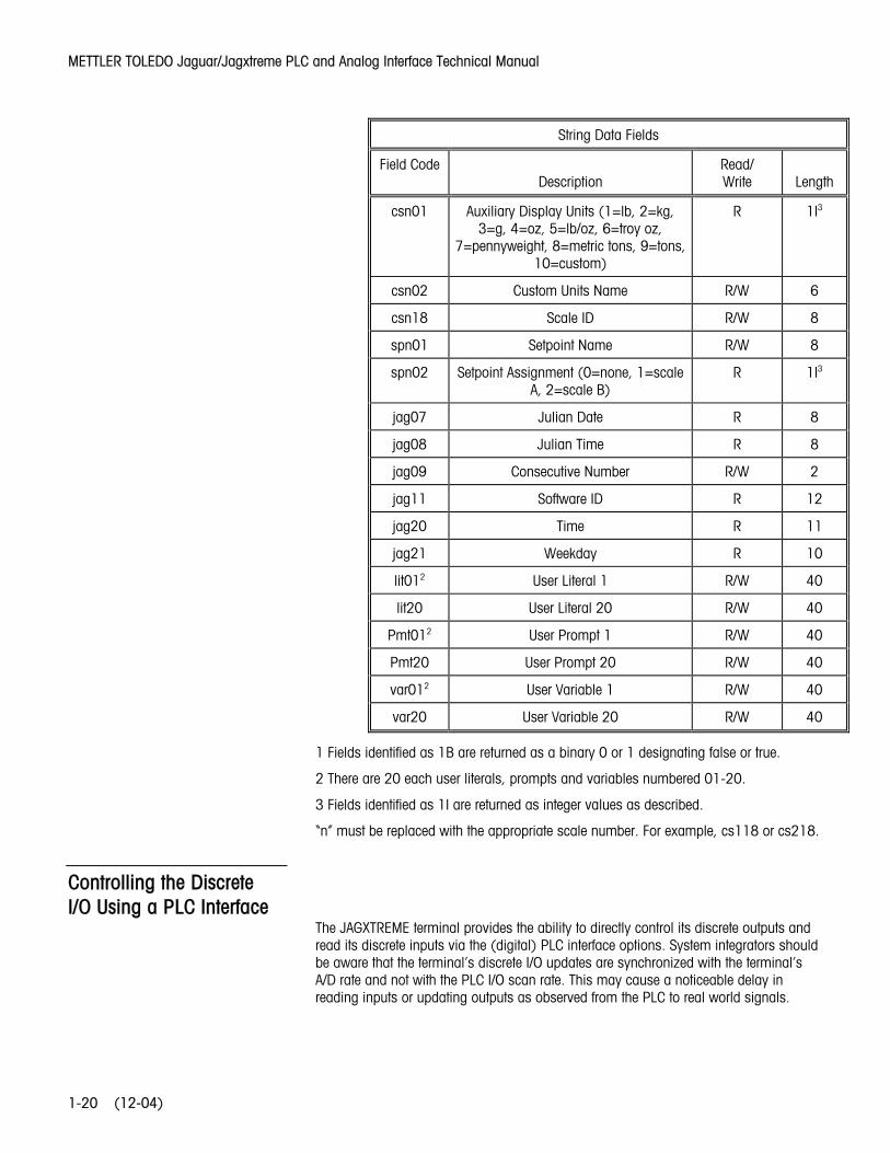
String Data Fields
Field Code Description
Read/ Write
Length
csn01 Auxiliary Display Units (1=lb, 2=kg, 3=g, 4=oz, 5=lb/oz, 6=troy oz,
7=pennyweight, 8=metric tons, 9=tons, 10=custom)
R 1I3
csn02 Custom Units Name R/W 6
csn18 Scale ID R/W 8
spn01 Setpoint Name R/W 8
spn02 Setpoint Assignment (0=none, 1=scale A, 2=scale B)
R 1I3
jag07 Julian Date R 8
jag08 Julian Time R 8
jag09 Consecutive Number R/W 2
jag11 Software ID R 12
jag20 Time R 11
jag21 Weekday R 10
lit012 User Literal 1 R/W 40
lit20 User Literal 20 R/W 40
Pmt012 User Prompt 1 R/W 40
Pmt20 User Prompt 20 R/W 40
var012 User Variable 1 R/W 40
var20 User Variable 20 R/W 40
1 Fields identified as 1B are returned as a binary 0 or 1 designating false or true.
2 There are 20 each user literals, prompts and variables numbered 01-20.
3 Fields identified as 1I are returned as integer values as described.
“n” must be replaced with the appropriate scale number. For example, cs118 or cs218.
Controlling the Discrete I/O Using a PLC Interface
The JAGXTREME terminal provides the ability to directly control its discrete outputs and read its discrete inputs via the (digital) PLC interface options. System integrators should be aware that the terminal’s discrete I/O updates are synchronized with the terminal’s A/D rate and not with the PLC I/O scan rate. This may cause a noticeable delay in reading inputs or updating outputs as observed from the PLC to real world signals.
(12-04) 1-20
Chapter 1: Allen-Bradley RIO Option Card Hardware Setup
Hardware Setup
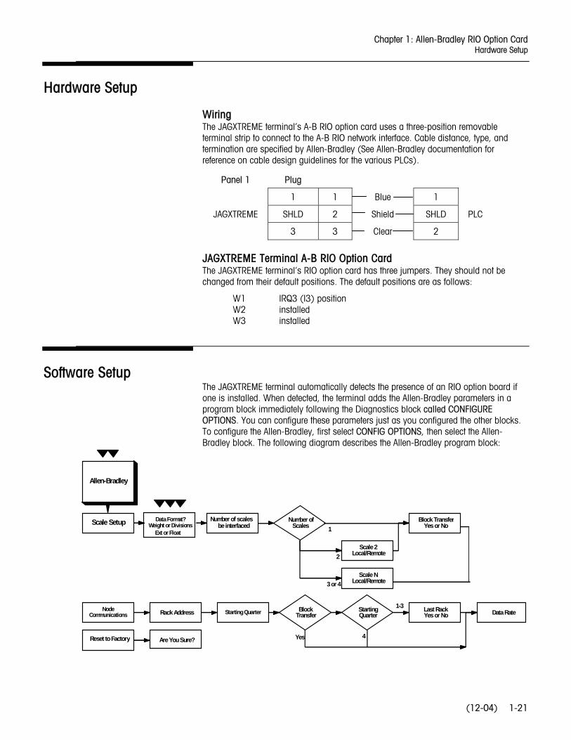
Wiring The JAGXTREME terminal’s A-B RIO option card uses a three-position removable terminal strip to connect to the A-B RIO network interface. Cable distance, type, and termination are specified by Allen-Bradley (See Allen-Bradley documentation for reference on cable design guidelines for the various PLCs).
Panel 1 Plug
1 1 Blue 1
JAGXTREME SHLD 2 Shield SHLD PLC
3 3 Clear 2
JAGXTREME Terminal A-B RIO Option Card The JAGXTREME terminal’s RIO option card has three jumpers. They should not be changed from their default positions. The default positions are as follows:
W1 IRQ3 (I3) position W2 installed W3 installed
Allen-Bradley
Scale Setup
Scale NLocal/Remote
NodeCommunications
Reset to Factory
StartingQuarter
Number of scalest be interfaced
Rack Address
Are You Sure?
Number ofScales
Starting Quarter
Block TransferYes or No
Scale 2Local/Remote
Last RackYes or No Data Rate
Data Format?Weight or Divisions
Ext or Float
BlockTransfer
Yes
1-3
2
1
3 or 4
4
Software Setup The JAGXTREME terminal automatically detects the presence of an RIO option board if one is installed. When detected, the terminal adds the Allen-Bradley parameters in a program block immediately following the Diagnostics block called CONFIGURE OPTIONS. You can configure these parameters just as you configured the other blocks. To configure the Allen-Bradley, first select CONFIG OPTIONS, then select the Allen-Bradley block. The following diagram describes the Allen-Bradley program block:
(12-04) 1-21
METTLER TOLEDO Jaguar/Jagxtreme PLC and Analog Interface Technical Manual
Scale Setup Sub-block The Scale Setup sub-block lets you specify how the Allen-Bradley interface is used. Several options are available to correspond with your system setup.
To configure the block: You must enter setup and configure each scale that is interfaced with the A-B RIO network. Refer to the JAGXTREME Terminal Technical Manual for details on configuring the Network Program Block.
Press ENTER at the Allen-Bradley prompt to access the program block.
Press ENTER at the Scale Setup prompt. At the Data Format? prompt, press SELECT to choose the desired weight display option:
Wgt—displays scale weight in the selected weight unit (lb, kg, or g).
Div—displays scale weight in display divisions. The PLC multiplies the display divisions by the increment size to calculate the weight in display units.
Ext—displays scale weight in the extended 21 signed bit format. The divisions display option is useful for heavy capacity scales that exceed the ± 32767 range of a signed integer in displayed weight units.
Flt---displays weight in floating point data format
• Refer to the Discrete Read and Discrete Write tables in this manual for additional information on mapping of discrete read data to the PLC.
• At the Nbr of Scales? prompt, press SELECT to display the number of scales to be interfaced (1, 2, 3, or 4).
If 1 or 2 Scales or No Scales Remote • At the Blk Transfer? prompt, select Y(es) if the A-B RIO will communicate with the
JAGXTREME terminal using block transfer. Select N(o) if block transfer is not required.
Local refers to a scale in the same terminal as the A-B option card. Remote refers to a scale interfaced across Ethernet.
If 2 or More Scales • At the Scale N? prompt, press SELECT to indicate if the designated scale is local or
remote.
• For remote scales, select the terminal number (Ethernet node location) at the Node? prompt.
• At the Internal Scale? prompt, identify each scale as A, B, C or D.
Press ENTER to go to the next sub-block or ESCAPE to exit setup mode.
(12-04) 1-22
Chapter 1: Allen-Bradley RIO Option Card Troubleshooting
Node Communications Sub-block
This sub-block lets you enter the Allen-Bradley RIO network communication parameters. The JAGXTREME terminal programs the Node Adapter Chip with these parameters.
This manual does not provide all information and configuration parameters for an Allen-Bradley network. Refer to Allen-Bradley documentation for information on specific network performance.
If block transfer is enabled, steps 3 and 4 do not apply. Continue to step 5.
If enabled, block transfer always uses the first quarter. The first scale is the second quarter, and the second scale is the third quarter.
1. Press ENTER at the Node Communicate prompt to configure communications parameters.
2. At the Rack Address? prompt, use the numeric keys to input the rack address (0-64 octal), then press ENTER.
3. At the Start Quarter? prompt, press SELECT to choose the starting quarter address (1-4). This prompt may be omitted depending on the data format and number of scales.
4. At the Last Rack? prompt, select Y(es) if the rack is the last quarter of this rack address, or N(o) if it is not.
5. At the Data Rate? prompt, press SELECT to choose the appropriate baud rate (57.6k, 115.2k, 230.4k).
Reset to Factory returns all parameters for this block to their original settings. You cannot reset a single value or specify only a few of the sub-block values.
Reset to Factory Sub-block If desired, you can reset all of the parameters for this program block to the original default values. To reset the program block parameters:
Press ENTER at the Reset to Factory prompt.
At the Are You Sure? prompt, press SELECT to highlight Y(es) to confirm and reset the values to factory defaults, or select N(o) if you do not wish to reset the values.
Press ESCAPE to exit the sub-block.
Press SELECT to continue to another program block if desired.
Troubleshooting
A-B RIO Option PCB Status Lights
The A-B RIO option card has a status LED that operates in three modes to indicate the following:
ON Normal operation
Flashing PLC in program mode
OFF Communication problem between JAGXTREME terminal and PLC
(12-04) 1-23
METTLER TOLEDO Jaguar/Jagxtreme PLC and Analog Interface Technical Manual
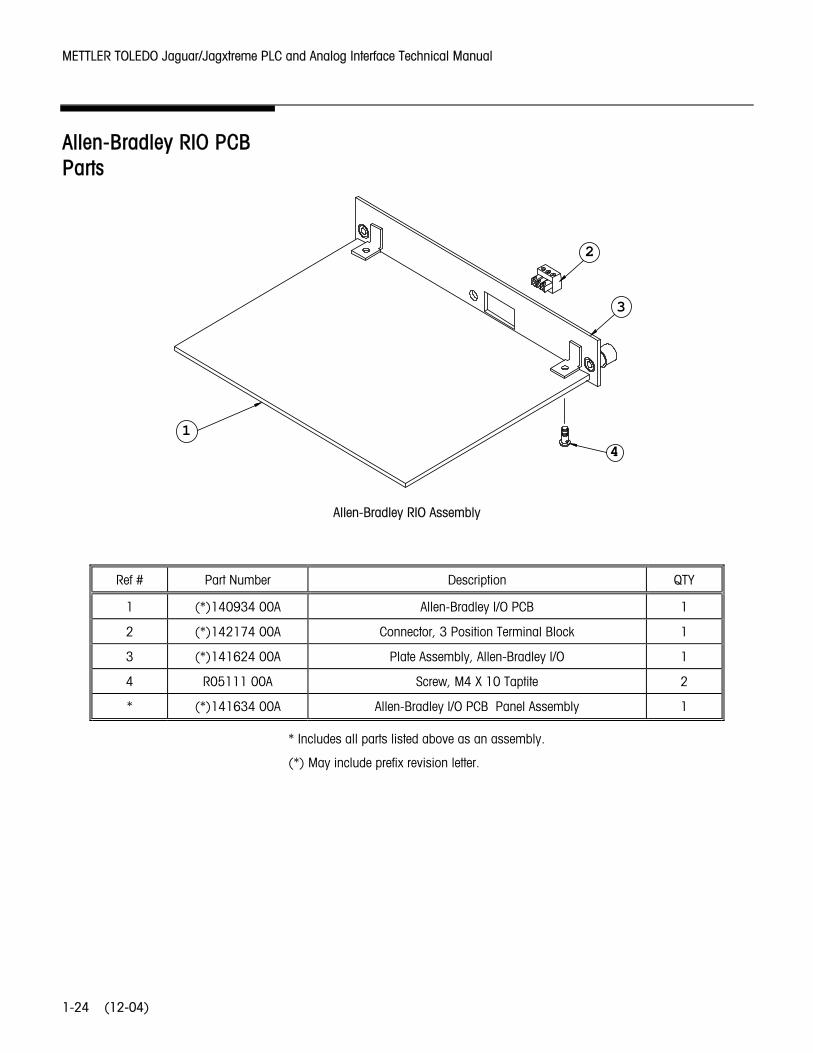
Allen-Bradley RIO PCB Parts
1
3
2
4
Allen-Bradley RIO Assembly
Ref # Part Number Description QTY
1 (*)140934 00A Allen-Bradley I/O PCB 1
2 (*)142174 00A Connector, 3 Position Terminal Block 1
3 (*)141624 00A Plate Assembly, Allen-Bradley I/O 1
4 R05111 00A Screw, M4 X 10 Taptite 2
* (*)141634 00A Allen-Bradley I/O PCB Panel Assembly 1
* Includes all parts listed above as an assembly.
(*) May include prefix revision letter.
(12-04) 1-24
Chapter 1: Allen-Bradley RIO Option Card Interfacing Examples
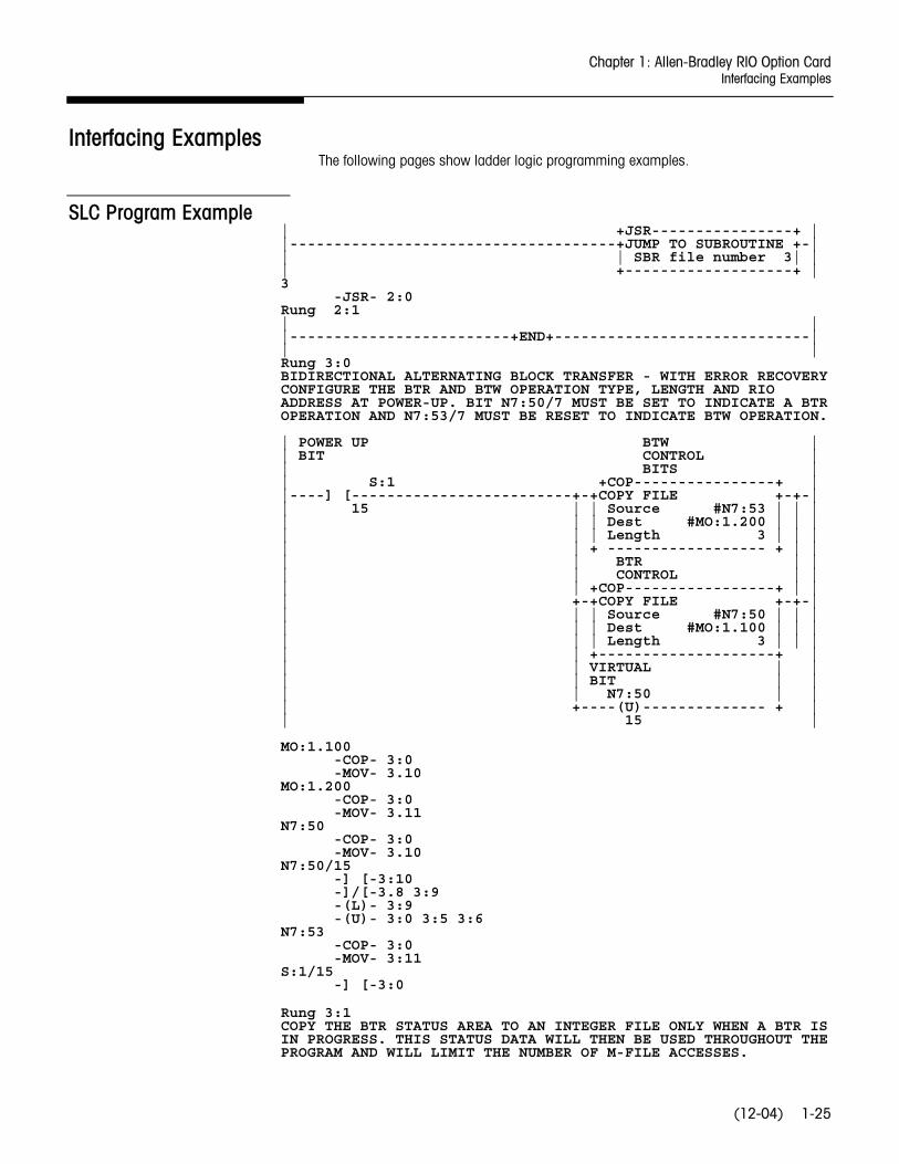
Interfacing Examples The following pages show ladder logic programming examples.
SLC Program Example | +JSR----------------+ | |-------------------------------------+JUMP TO SUBROUTINE +-| | | SBR file number 3| | | +-------------------+ | 3 -JSR- 2:0 Rung 2:1 | | |-------------------------+END+-----------------------------| | | Rung 3:0 BIDIRECTIONAL ALTERNATING BLOCK TRANSFER - WITH ERROR RECOVERY CONFIGURE THE BTR AND BTW OPERATION TYPE, LENGTH AND RIO ADDRESS AT POWER-UP. BIT N7:50/7 MUST BE SET TO INDICATE A BTR OPERATION AND N7:53/7 MUST BE RESET TO INDICATE BTW OPERATION. | POWER UP BTW | | BIT CONTROL | | BITS | | S:1 +COP----------------+ | |----] [-------------------------+-+COPY FILE +-+-| | 15 | | Source #N7:53 | | | | | | Dest #MO:1.200 | | | | | | Length 3 | | | | | + ------------------ + | | | | BTR | | | | CONTROL | | | | +COP-----------------+ | | | +-+COPY FILE +-+-| | | | Source #N7:50 | | | | | | Dest #MO:1.100 | | | | | | Length 3 | | | | | +--------------------+ | | | VIRTUAL | | | | BIT | | | | N7:50 | | | +----(U)-------------- + | | 15 | MO:1.100 -COP- 3:0 -MOV- 3.10 MO:1.200 -COP- 3:0 -MOV- 3.11 N7:50 -COP- 3:0 -MOV- 3.10 N7:50/15 -] [-3:10 -]/[-3.8 3:9 -(L)- 3:9 -(U)- 3:0 3:5 3:6 N7:53 -COP- 3:0 -MOV- 3:11 S:1/15 -] [-3:0 Rung 3:1 COPY THE BTR STATUS AREA TO AN INTEGER FILE ONLY WHEN A BTR IS IN PROGRESS. THIS STATUS DATA WILL THEN BE USED THROUGHOUT THE PROGRAM AND WILL LIMIT THE NUMBER OF M-FILE ACCESSES.
(12-04) 1-25
METTLER TOLEDO Jaguar/Jagxtreme PLC and Analog Interface Technical Manual
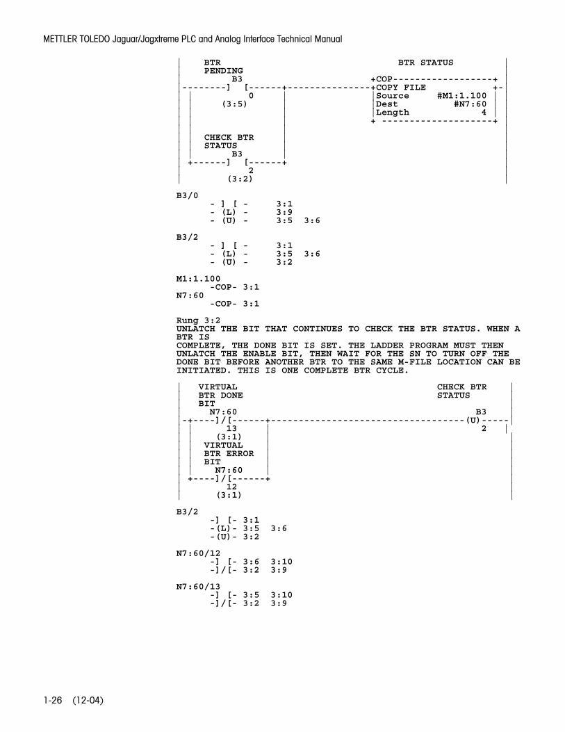
| BTR BTR STATUS | | PENDING | | B3 +COP------------------+ | |--------] [------+---------------+COPY FILE +-| | | 0 | |Source #M1:1.100 | | | | (3:5) | |Dest #N7:60 | | | | | |Length 4 | | | | | + --------------------+ | | | | | | | CHECK BTR | | | | STATUS | | | | B3 | | | +------] [------+ | | 2 | | (3:2) | B3/0 - ] [ - 3:1 - (L) - 3:9 - (U) - 3:5 3:6 B3/2 - ] [ - 3:1 - (L) - 3:5 3:6 - (U) - 3:2 M1:1.100 -COP- 3:1 N7:60 -COP- 3:1 Rung 3:2 UNLATCH THE BIT THAT CONTINUES TO CHECK THE BTR STATUS. WHEN A BTR IS COMPLETE, THE DONE BIT IS SET. THE LADDER PROGRAM MUST THEN UNLATCH THE ENABLE BIT, THEN WAIT FOR THE SN TO TURN OFF THE DONE BIT BEFORE ANOTHER BTR TO THE SAME M-FILE LOCATION CAN BE INITIATED. THIS IS ONE COMPLETE BTR CYCLE. | VIRTUAL CHECK BTR | | BTR DONE STATUS | | BIT | | N7:60 B3 | |-+----]/[------+-----------------------------------(U)-----| | | 13 | 2 | | | (3:1) | | | | VIRTUAL | | | | BTR ERROR | | | | BIT | | | | N7:60 | | | +----]/[------+ | | 12 | | (3:1) | B3/2 -] [- 3:1 -(L)- 3:5 3:6 -(U)- 3:2 N7:60/12 -] [- 3:6 3:10 -]/[- 3:2 3:9 N7:60/13 -] [- 3:5 3:10 -]/[- 3:2 3:9
(12-04) 1-26
Chapter 1: Allen-Bradley RIO Option Card Interfacing Examples
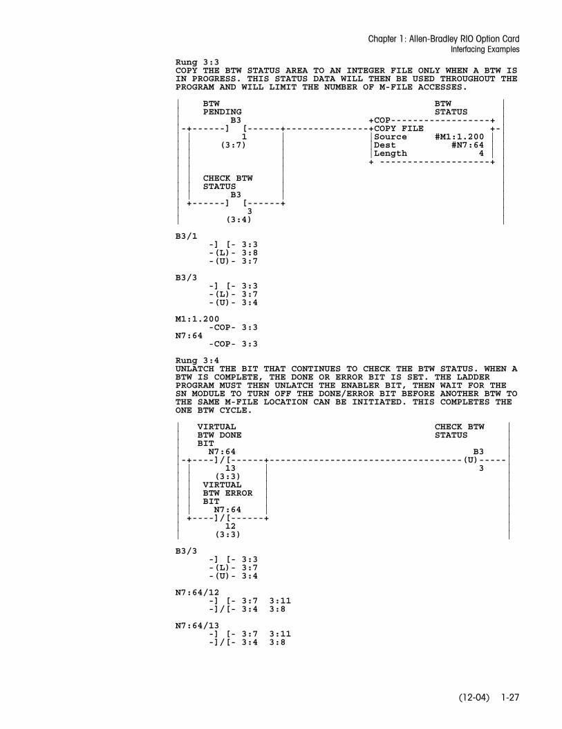
Rung 3:3 COPY THE BTW STATUS AREA TO AN INTEGER FILE ONLY WHEN A BTW IS IN PROGRESS. THIS STATUS DATA WILL THEN BE USED THROUGHOUT THE PROGRAM AND WILL LIMIT THE NUMBER OF M-FILE ACCESSES. | BTW BTW | | PENDING STATUS | | B3 +COP------------------+ | |-+------] [------+---------------+COPY FILE +-| | | 1 | |Source #M1:1.200 | | | | (3:7) | |Dest #N7:64 | | | | | |Length 4 | | | | | + --------------------+ | | | | | | | CHECK BTW | | | | STATUS | | | | B3 | | | +------] [------+ | | 3 | | (3:4) | B3/1 -] [- 3:3 -(L)- 3:8 -(U)- 3:7 B3/3 -] [- 3:3 -(L)- 3:7 -(U)- 3:4 M1:1.200 -COP- 3:3 N7:64 -COP- 3:3 Rung 3:4 UNLATCH THE BIT THAT CONTINUES TO CHECK THE BTW STATUS. WHEN A BTW IS COMPLETE, THE DONE OR ERROR BIT IS SET. THE LADDER PROGRAM MUST THEN UNLATCH THE ENABLER BIT, THEN WAIT FOR THE SN MODULE TO TURN OFF THE DONE/ERROR BIT BEFORE ANOTHER BTW TO THE SAME M-FILE LOCATION CAN BE INITIATED. THIS COMPLETES THE ONE BTW CYCLE. | VIRTUAL CHECK BTW | | BTW DONE STATUS | | BIT | | N7:64 B3 | |-+----]/[------+-----------------------------------(U)-----| | | 13 | 3 | | | (3:3) | | | | VIRTUAL | | | | BTW ERROR | | | | BIT | | | | N7:64 | | | +----]/[------+ | | 12 | | (3:3) | B3/3 -] [- 3:3 -(L)- 3:7 -(U)- 3:4 N7:64/12 -] [- 3:7 3:11 -]/[- 3:4 3:8 N7:64/13 -] [- 3:7 3:11 -]/[- 3:4 3:8
(12-04) 1-27
METTLER TOLEDO Jaguar/Jagxtreme PLC and Analog Interface Technical Manual
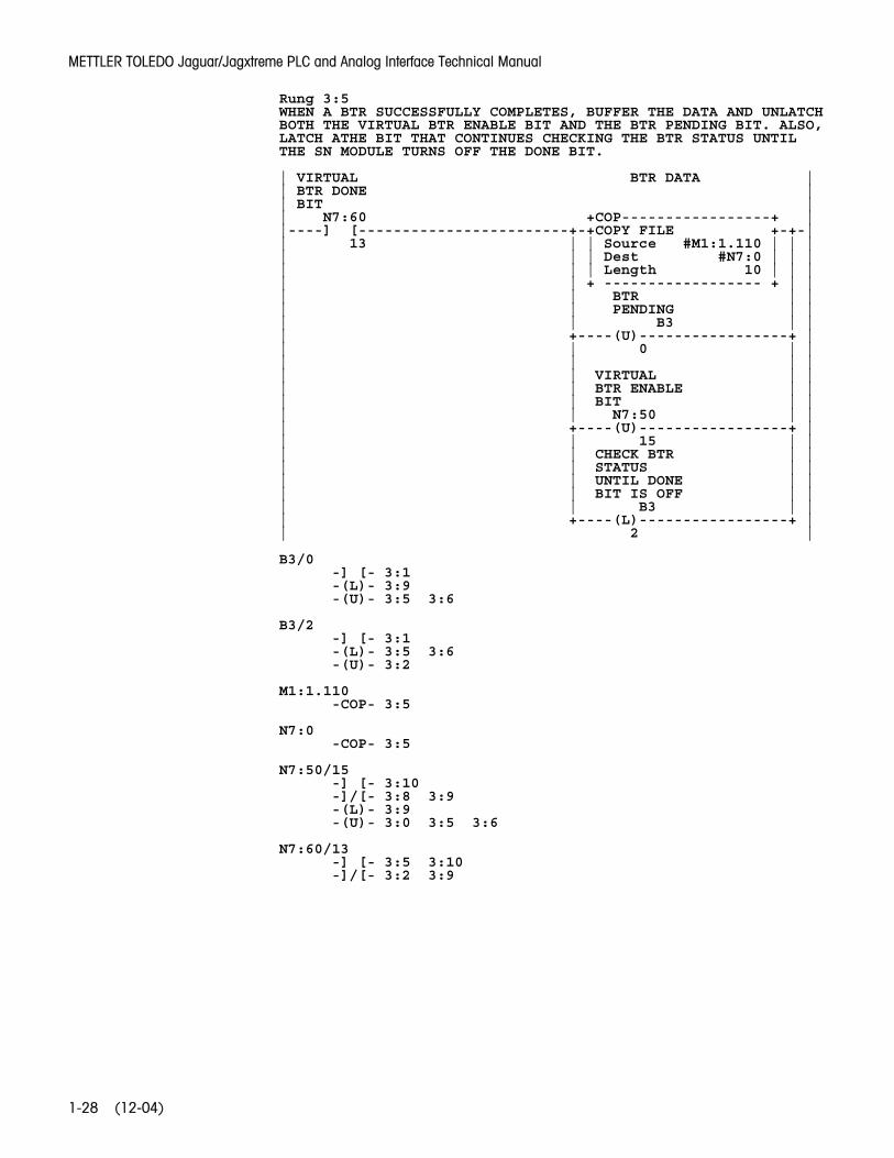
Rung 3:5 WHEN A BTR SUCCESSFULLY COMPLETES, BUFFER THE DATA AND UNLATCH BOTH THE VIRTUAL BTR ENABLE BIT AND THE BTR PENDING BIT. ALSO, LATCH ATHE BIT THAT CONTINUES CHECKING THE BTR STATUS UNTIL THE SN MODULE TURNS OFF THE DONE BIT. | VIRTUAL BTR DATA | | BTR DONE | | BIT | | N7:60 +COP-----------------+ | |----] [------------------------+-+COPY FILE +-+-| | 13 | | Source #M1:1.110 | | | | | | Dest #N7:0 | | | | | | Length 10 | | | | | + ------------------ + | | | | BTR | | | | PENDING | | | | B3 | | | +----(U)-----------------+ | | | 0 | | | | | | | | VIRTUAL | | | | BTR ENABLE | | | | BIT | | | | N7:50 | | | +----(U)-----------------+ | | | 15 | | | | CHECK BTR | | | | STATUS | | | | UNTIL DONE | | | | BIT IS OFF | | | | B3 | | | +----(L)-----------------+ | | 2 | B3/0 -] [- 3:1 -(L)- 3:9 -(U)- 3:5 3:6 B3/2 -] [- 3:1 -(L)- 3:5 3:6 -(U)- 3:2 M1:1.110 -COP- 3:5 N7:0 -COP- 3:5 N7:50/15 -] [- 3:10 -]/[- 3:8 3:9 -(L)- 3:9 -(U)- 3:0 3:5 3:6 N7:60/13 -] [- 3:5 3:10 -]/[- 3:2 3:9
(12-04) 1-28
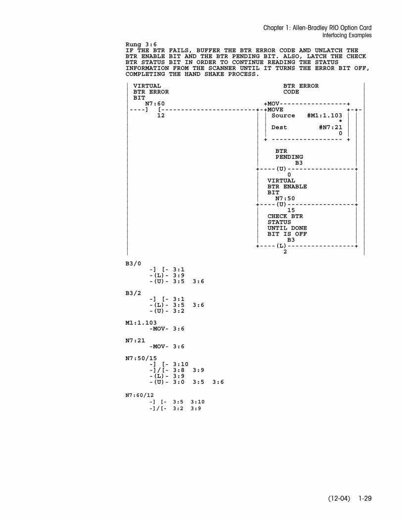
Chapter 1: Allen-Bradley RIO Option Card Interfacing Examples
Rung 3:6 IF THE BTR FAILS, BUFFER THE BTR ERROR CODE AND UNLATCH THE BTR ENABLE BIT AND THE BTR PENDING BIT. ALSO, LATCH THE CHECK BTR STATUS BIT IN ORDER TO CONTINUE READING THE STATUS INFORMATION FROM THE SCANNER UNTIL IT TURNS THE ERROR BIT OFF, COMPLETING THE HAND SHAKE PROCESS. | VIRTUAL BTR ERROR | | BTR ERROR CODE | | BIT | | N7:60 +MOV-----------------+ | |----] [------------------------+-+MOVE +-+-| | 12 | | Source #M1:1.103 | | | | | | * | | | | | | Dest #N7:21 | | | | | | 0 | | | | | + ------------------ + | | | | | | | | BTR | | | | PENDING | | | | B3 | | | +----(U)-----------------+ | | | 0 | | | | VIRTUAL | | | | BTR ENABLE | | | | BIT | | | | N7:50 | | | +----(U)-----------------+ | | | 15 | | | | CHECK BTR | | | | STATUS | | | | UNTIL DONE | | | | BIT IS OFF | | | | B3 | | | +----(L)-----------------+ | | 2 | B3/0 -] [- 3:1 -(L)- 3:9 -(U)- 3:5 3:6 B3/2 -] [- 3:1 -(L)- 3:5 3:6 -(U)- 3:2 M1:1.103 -MOV- 3:6 N7:21 -MOV- 3:6 N7:50/15 -] [- 3:10 -]/[- 3:8 3:9 -(L)- 3:9 -(U)- 3:0 3:5 3:6 N7:60/12 -] [- 3:5 3:10 -]/[- 3:2 3:9
(12-04) 1-29
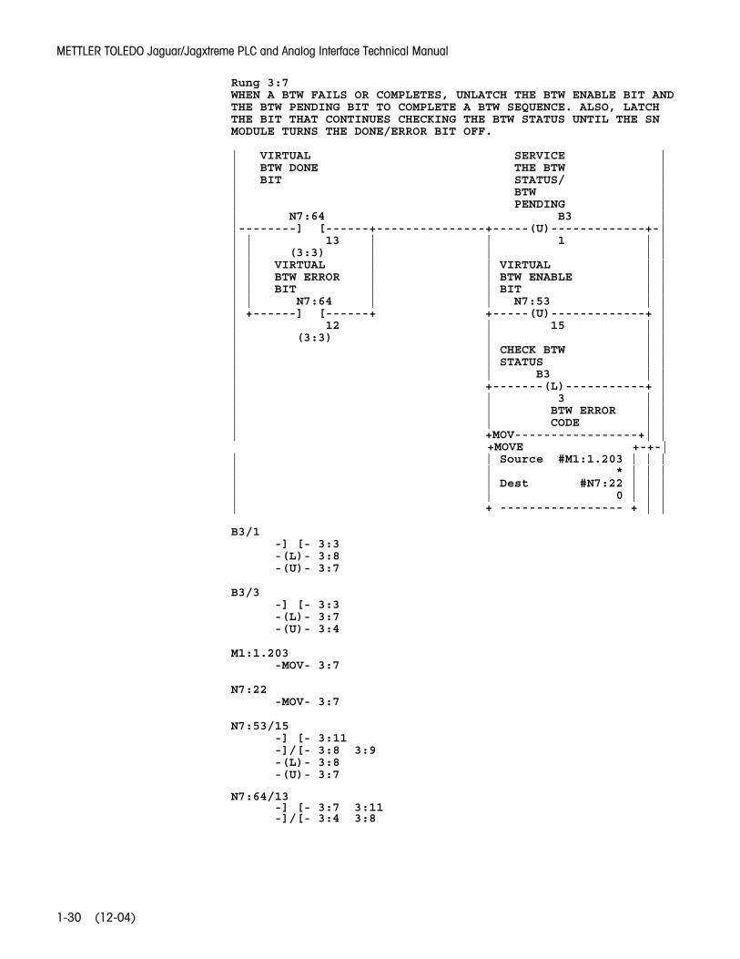
METTLER TOLEDO Jaguar/Jagxtreme PLC and Analog Interface Technical Manual
Rung 3:7 WHEN A BTW FAILS OR COMPLETES, UNLATCH THE BTW ENABLE BIT AND THE BTW PENDING BIT TO COMPLETE A BTW SEQUENCE. ALSO, LATCH THE BIT THAT CONTINUES CHECKING THE BTW STATUS UNTIL THE SN MODULE TURNS THE DONE/ERROR BIT OFF. | VIRTUAL SERVICE | | BTW DONE THE BTW | | BIT STATUS/ | | BTW | | PENDING | | N7:64 B3 | |--------] [------+---------------+-----(U)-------------+-| | | 13 | | 1 | | | | (3:3) | | | | | | VIRTUAL | | VIRTUAL | | | | BTW ERROR | | BTW ENABLE | | | | BIT | | BIT | | | | N7:64 | | N7:53 | | | +------] [------+ +-----(U)-------------+ | | 12 | 15 | | | (3:3) | | | | | CHECK BTW | | | | STATUS | | | | B3 | | | +-------(L)-----------+ | | | 3 | | | | BTW ERROR | | | | CODE | | | +MOV-----------------+| |
+MOVE +-+-| | | Source #M1:1.203 | | | | | * | | | | | Dest #N7:22 | | | | | 0 | | | | + ----------------- + | | B3/1 -] [- 3:3 -(L)- 3:8 -(U)- 3:7 B3/3 -] [- 3:3 -(L)- 3:7 -(U)- 3:4 M1:1.203 -MOV- 3:7 N7:22 -MOV- 3:7 N7:53/15 -] [- 3:11 -]/[- 3:8 3:9 -(L)- 3:8 -(U)- 3:7 N7:64/13 -] [- 3:7 3:11 -]/[- 3:4 3:8
(12-04) 1-30
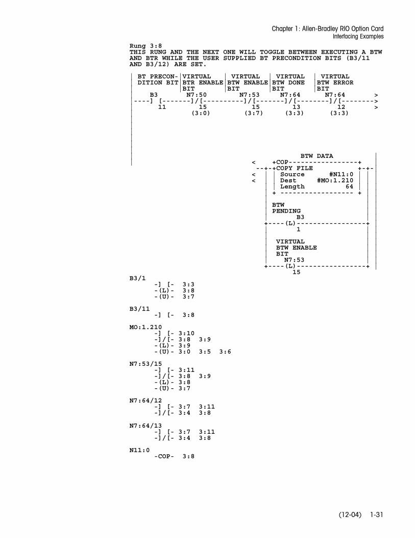
Chapter 1: Allen-Bradley RIO Option Card Interfacing Examples
Rung 3:8 THIS RUNG AND THE NEXT ONE WILL TOGGLE BETWEEN EXECUTING A BTW AND BTR WHILE THE USER SUPPLIED BT PRECONDITION BITS (B3/11 AND B3/12) ARE SET. | BT PRECON-|VIRTUAL | VIRTUAL | VIRTUAL | VIRTUAL | DITION BIT|BTR ENABLE|BTW ENABLE|BTW DONE |BTW ERROR | |BIT |BIT |BIT |BIT | B3 N7:50 N7:53 N7:64 N7:64 > |----] [-------]/[----------]/[-------]/[--------]/[--------> | 11 15 15 13 12 > | (3:0) (3:7) (3:3) (3:3) | | | | | | | BTW DATA | | < +COP-----------------+ | --+-+COPY FILE +-+-| < | | Source #N11:0 | | | < | | Dest #MO:1.210 | | | | | Length 64 | | | | + ------------------ + | | | | | | BTW | | | PENDING | | | B3 | | +----(L)-----------------+ | | 1 | | | | | | VIRTUAL | | | BTW ENABLE | | | BIT | | | N7:53 | | +----(L)-----------------+ | 15 B3/1 -] [- 3:3 -(L)- 3:8 -(U)- 3:7 B3/11 -] [- 3:8 MO:1.210 -] [- 3:10 -]/[- 3:8 3:9 -(L)- 3:9 -(U)- 3:0 3:5 3:6 N7:53/15 -] [- 3:11 -]/[- 3:8 3:9 -(L)- 3:8 -(U)- 3:7 N7:64/12 -] [- 3:7 3:11 -]/[- 3:4 3:8 N7:64/13 -] [- 3:7 3:11 -]/[- 3:4 3:8 N11:0 -COP- 3:8
(12-04) 1-31
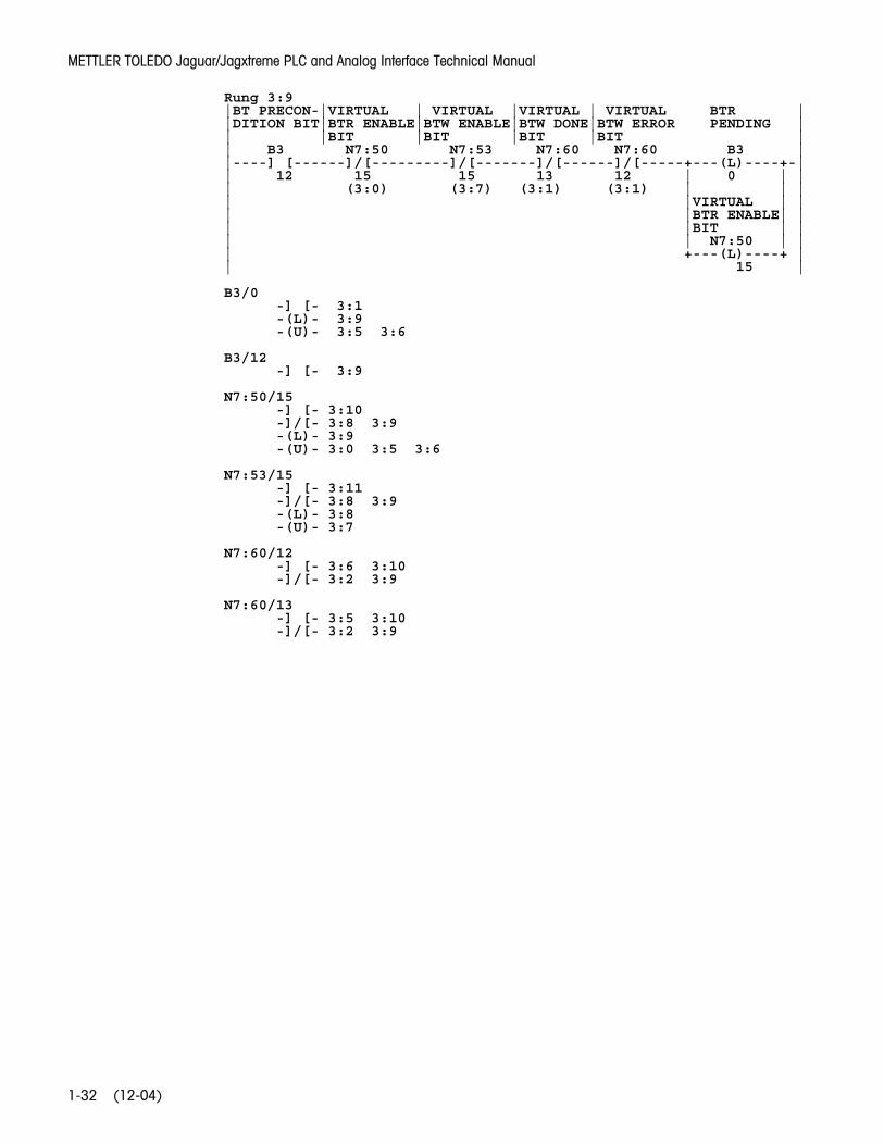
METTLER TOLEDO Jaguar/Jagxtreme PLC and Analog Interface Technical Manual
Rung 3:9 |BT PRECON-|VIRTUAL | VIRTUAL |VIRTUAL | VIRTUAL BTR | |DITION BIT|BTR ENABLE|BTW ENABLE|BTW DONE|BTW ERROR PENDING | | |BIT |BIT |BIT |BIT | | B3 N7:50 N7:53 N7:60 N7:60 B3 | |----] [------]/[---------]/[-------]/[------]/[-----+---(L)----+-| | 12 15 15 13 12 | 0 | | | (3:0) (3:7) (3:1) (3:1) | | | | |VIRTUAL | | | |BTR ENABLE| | | |BIT | | | | N7:50 | | | +---(L)----+ | | 15 | B3/0 -] [- 3:1 -(L)- 3:9 -(U)- 3:5 3:6 B3/12 -] [- 3:9 N7:50/15 -] [- 3:10 -]/[- 3:8 3:9 -(L)- 3:9 -(U)- 3:0 3:5 3:6 N7:53/15 -] [- 3:11 -]/[- 3:8 3:9 -(L)- 3:8 -(U)- 3:7 N7:60/12 -] [- 3:6 3:10 -]/[- 3:2 3:9 N7:60/13 -] [- 3:5 3:10 -]/[- 3:2 3:9
(12-04) 1-32
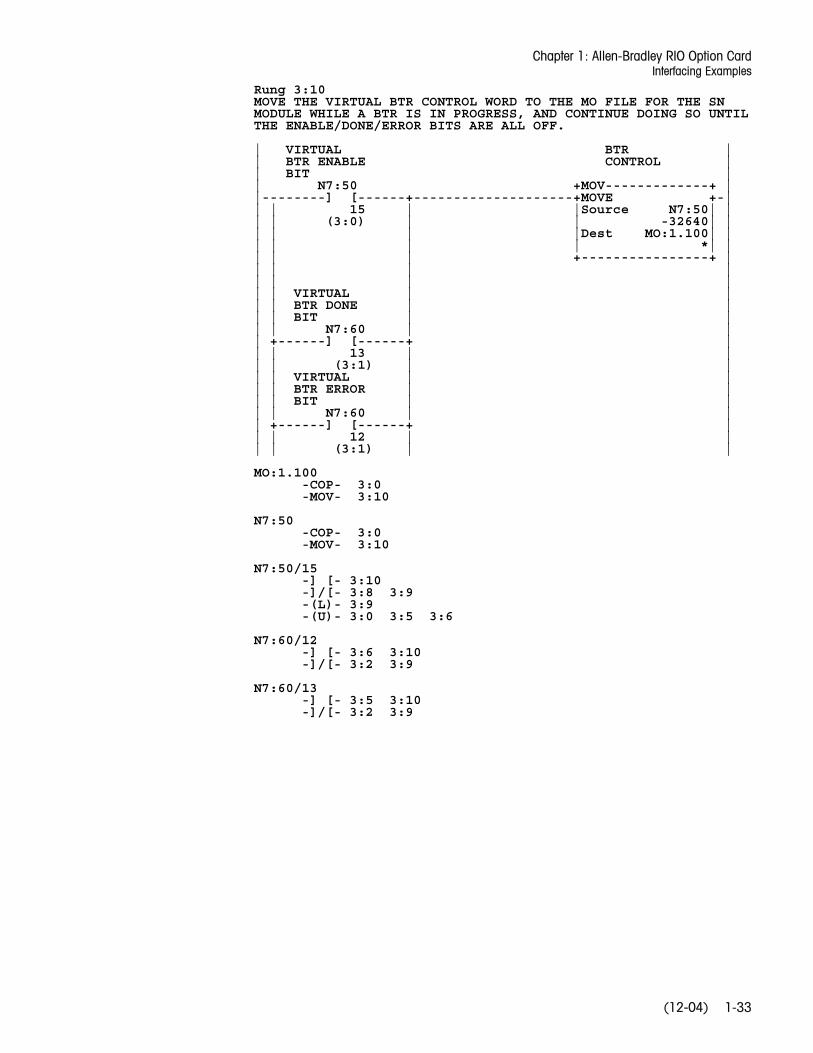
Chapter 1: Allen-Bradley RIO Option Card Interfacing Examples
Rung 3:10 MOVE THE VIRTUAL BTR CONTROL WORD TO THE MO FILE FOR THE SN MODULE WHILE A BTR IS IN PROGRESS, AND CONTINUE DOING SO UNTIL THE ENABLE/DONE/ERROR BITS ARE ALL OFF. | VIRTUAL BTR | | BTR ENABLE CONTROL | | BIT | | N7:50 +MOV-------------+ | |--------] [------+--------------------+MOVE +-| | | 15 | |Source N7:50| | | | (3:0) | | -32640| | | | | |Dest MO:1.100| | | | | | *| | | | | +----------------+ | | | | | | | | | | | VIRTUAL | | | | BTR DONE | | | | BIT | | | | N7:60 | | | +------] [------+ | | | 13 | | | | (3:1) | | | | VIRTUAL | | | | BTR ERROR | | | | BIT | | | | N7:60 | | | +------] [------+ | | | 12 | | | | (3:1) | | MO:1.100 -COP- 3:0 -MOV- 3:10 N7:50 -COP- 3:0 -MOV- 3:10 N7:50/15 -] [- 3:10 -]/[- 3:8 3:9 -(L)- 3:9 -(U)- 3:0 3:5 3:6 N7:60/12 -] [- 3:6 3:10 -]/[- 3:2 3:9 N7:60/13 -] [- 3:5 3:10 -]/[- 3:2 3:9
(12-04) 1-33
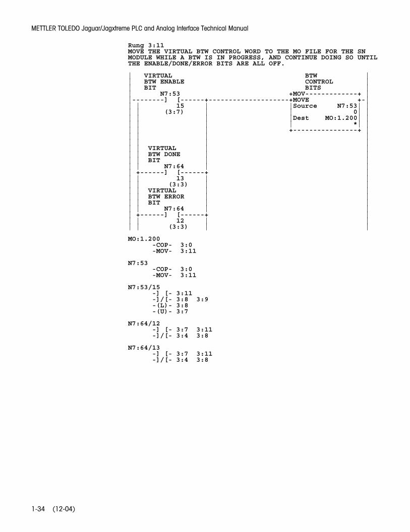
METTLER TOLEDO Jaguar/Jagxtreme PLC and Analog Interface Technical Manual
Rung 3:11 MOVE THE VIRTUAL BTW CONTROL WORD TO THE MO FILE FOR THE SN MODULE WHILE A BTW IS IN PROGRESS, AND CONTINUE DOING SO UNTIL THE ENABLE/DONE/ERROR BITS ARE ALL OFF. | VIRTUAL BTW | | BTW ENABLE CONTROL | | BIT BITS | | N7:53 +MOV-------------+ | |--------] [------+--------------------+MOVE +-| | | 15 | |Source N7:53| | | | (3:7) | | 0| | | | | |Dest MO:1.200| | | | | | *| | | | | +----------------+ | | | | | | | | | | | VIRTUAL | | | | BTW DONE | | | | BIT | | | | N7:64 | | | +------] [------+ | | | 13 | | | | (3:3) | | | | VIRTUAL | | | | BTW ERROR | | | | BIT | | | | N7:64 | | | +------] [------+ | | | 12 | | | | (3:3) | | MO:1.200 -COP- 3:0 -MOV- 3:11 N7:53 -COP- 3:0 -MOV- 3:11 N7:53/15 -] [- 3:11 -]/[- 3:8 3:9 -(L)- 3:8 -(U)- 3:7 N7:64/12 -] [- 3:7 3:11 -]/[- 3:4 3:8 N7:64/13 -] [- 3:7 3:11 -]/[- 3:4 3:8
(12-04) 1-34
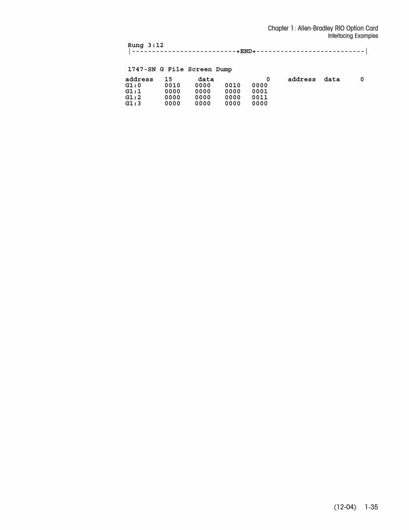
Chapter 1: Allen-Bradley RIO Option Card Interfacing Examples
Rung 3:12 |--------------------------+END+---------------------------| 1747-SN G File Screen Dump
address 15 data 0 address data 0 G1:0 0010 0000 0010 0000 G1:1 0000 0000 0000 0001 G1:2 0000 0000 0000 0011 G1:3 0000 0000 0000 0000
(12-04) 1-35
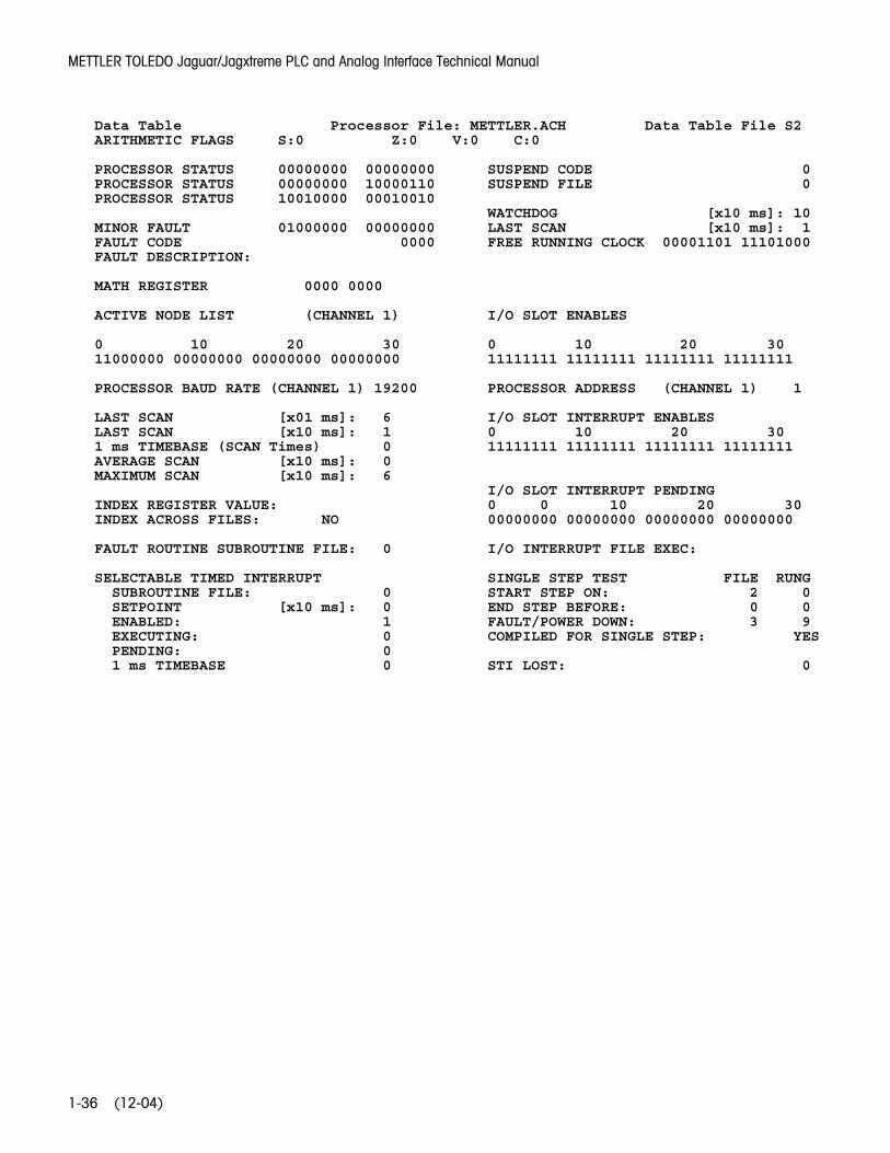
METTLER TOLEDO Jaguar/Jagxtreme PLC and Analog Interface Technical Manual
Data Table Processor File: METTLER.ACH Data Table File S2 ARITHMETIC FLAGS S:0 Z:0 V:0 C:0 PROCESSOR STATUS 00000000 00000000 SUSPEND CODE 0 PROCESSOR STATUS 00000000 10000110 SUSPEND FILE 0 PROCESSOR STATUS 10010000 00010010 WATCHDOG [x10 ms]: 10 MINOR FAULT 01000000 00000000 LAST SCAN [x10 ms]: 1 FAULT CODE 0000 FREE RUNNING CLOCK 00001101 11101000 FAULT DESCRIPTION: MATH REGISTER 0000 0000 ACTIVE NODE LIST (CHANNEL 1) I/O SLOT ENABLES 0 10 20 30 0 10 20 30 11000000 00000000 00000000 00000000 11111111 11111111 11111111 11111111 PROCESSOR BAUD RATE (CHANNEL 1) 19200 PROCESSOR ADDRESS (CHANNEL 1) 1 LAST SCAN [x01 ms]: 6 I/O SLOT INTERRUPT ENABLES LAST SCAN [x10 ms]: 1 0 10 20 30 1 ms TIMEBASE (SCAN Times) 0 11111111 11111111 11111111 11111111 AVERAGE SCAN [x10 ms]: 0 MAXIMUM SCAN [x10 ms]: 6 I/O SLOT INTERRUPT PENDING INDEX REGISTER VALUE: 0 0 10 20 30 INDEX ACROSS FILES: NO 00000000 00000000 00000000 00000000 FAULT ROUTINE SUBROUTINE FILE: 0 I/O INTERRUPT FILE EXEC: SELECTABLE TIMED INTERRUPT SINGLE STEP TEST FILE RUNG SUBROUTINE FILE: 0 START STEP ON: 2 0 SETPOINT [x10 ms]: 0 END STEP BEFORE: 0 0 ENABLED: 1 FAULT/POWER DOWN: 3 9 EXECUTING: 0 COMPILED FOR SINGLE STEP: YES PENDING: 0 1 ms TIMEBASE 0 STI LOST: 0
(12-04) 1-36
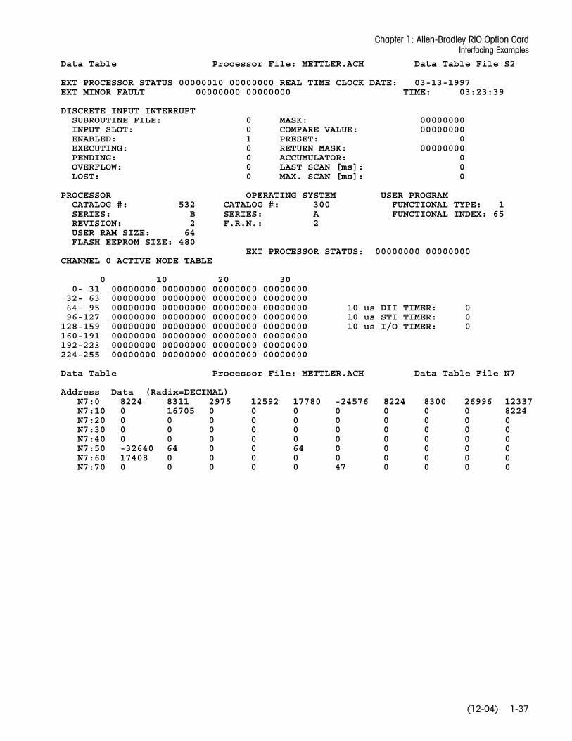
Chapter 1: Allen-Bradley RIO Option Card Interfacing Examples
Data Table Processor File: METTLER.ACH Data Table File S2 EXT PROCESSOR STATUS 00000010 00000000 REAL TIME CLOCK DATE: 03-13-1997 EXT MINOR FAULT 00000000 00000000 TIME: 03:23:39 DISCRETE INPUT INTERRUPT SUBROUTINE FILE: 0 MASK: 00000000 INPUT SLOT: 0 COMPARE VALUE: 00000000 ENABLED: 1 PRESET: 0 EXECUTING: 0 RETURN MASK: 00000000 PENDING: 0 ACCUMULATOR: 0 OVERFLOW: 0 LAST SCAN [ms]: 0 LOST: 0 MAX. SCAN [ms]: 0 PROCESSOR OPERATING SYSTEM USER PROGRAM CATALOG #: 532 CATALOG #: 300 FUNCTIONAL TYPE: 1 SERIES: B SERIES: A FUNCTIONAL INDEX: 65 REVISION: 2 F.R.N.: 2 USER RAM SIZE: 64 FLASH EEPROM SIZE: 480 EXT PROCESSOR STATUS: 00000000 00000000 CHANNEL 0 ACTIVE NODE TABLE 0 10 20 30 0- 31 00000000 00000000 00000000 00000000 32- 63 00000000 00000000 00000000 00000000 64- 95 00000000 00000000 00000000 00000000 10 us DII TIMER: 0 96-127 00000000 00000000 00000000 00000000 10 us STI TIMER: 0 128-159 00000000 00000000 00000000 00000000 10 us I/O TIMER: 0 160-191 00000000 00000000 00000000 00000000 192-223 00000000 00000000 00000000 00000000 224-255 00000000 00000000 00000000 00000000 Data Table Processor File: METTLER.ACH Data Table File N7 Address Data (Radix=DECIMAL)
N7:0 8224 8311 2975 12592 17780 -24576 8224 8300 26996 12337 N7:10 0 16705 0 0 0 0 0 0 0 8224 N7:20 0 0 0 0 0 0 0 0 0 0 N7:30 0 0 0 0 0 0 0 0 0 0 N7:40 0 0 0 0 0 0 0 0 0 0 N7:50 -32640 64 0 0 64 0 0 0 0 0 N7:60 17408 0 0 0 0 0 0 0 0 0 N7:70 0 0 0 0 0 47 0 0 0 0
(12-04) 1-37
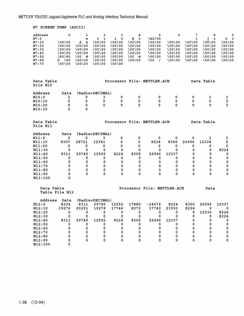
METTLER TOLEDO Jaguar/Jagxtreme PLC and Analog Interface Technical Manual
N7 SCREEN DUMP (ASCII) address 0 1 2 3 4 5 6 7 8 9 N7:0 w t 1 1 0 E t \A0/00 l j t 0 1 N7:10 \00\00 A A \00\00 \00\00 \00\00 \00\00 \00\00 \00\00 \00\00 \00\00 N7:20 \00\00 \00\00 \00\00 \00\00 \00\00 \00\00 \00\00 \00\00 \00\00 \00\00 N7:30 \00\00 \00\00 \00\00 \00\00 \00\00 \00\00 \00\00 \00\00 \00\00 \00\00 N7:40 \00\00 \00\00 \00\00 \00\00 \00\00 \00\00 \00\00 \00\00 \00\00 \00\00 N7:50 \80\80 \00 @ \00\00 \00\00 \00 @ \00\00 \00\00 \00\00 \00\00 \00\00 N7:60 D \00 \00\00 \00\00 \00\00 \00\00 \00 / \00\00 \00\00 \00\00 \00\00 N7:70 \00\00 \00\00 \00\00 \00\00 Data Table Processor File: METTLER.ACH Data Table File N10 Address Data (Radix=DECIMAL) N10:0 2 0 3 0 0 0 0 0 1 3N10:10 0 0 0 0 0 0 0 0 0 0N10:20 0 0 0 0 0 0 0 0 0 0N10:30 0 0 Data Table Processor File: METTLER.ACH Data Table File N11 Address Data (Radix=DECIMAL) N11:0 0 0 3 0 0 0 0 0 1 3N11:10 8307 28721 12341 0 0 8224 8300 26996 12338 0N11:20 0 0 0 0 0 0 0 0 0 0N11:30 0 0 0 0 0 0 0 0 0 8224N11:40 8311 29745 12592 8224 8300 26996 12337 0 0 0N11:50 0 0 0 0 0 0 0 0 0 0N11:60 0 0 0 0 0 0 0 0 0 0N11:70 0 0 0 0 0 0 0 0 0 0N11:80 0 0 0 0 0 0 0 0 0 0N11:90 0 0 0 0 0 0 0 0 0 0N11:100 0
Data Table Processor File: METTLER.ACH Data Table File N12 Address Data (Radix=DECIMAL)
N12:0 8224 8311 29745 12592 17880 -24576 8224 8300 26996 12337N12:10 19276 20291 19278 17746 8272 17742 21550 8224 0 0N12:20 0 0 0 0 0 0 0 0 12336 8224N12:30 0 0 0 0 0 0 0 0 0 8224N12:40 8311 29745 12592 8224 8300 26996 12337 0 0 0N12:50 0 0 0 0 0 0 0 0 0 0N12:60 0 0 0 0 0 0 0 0 0 0N12:70 0 0 0 0 0 0 0 0 0 0N12:80 0 0 0 0 0 0 0 0 0 0N12:90 0 0 0 0 0 0 0 0 0 0N12:100 0
(12-04) 1-38
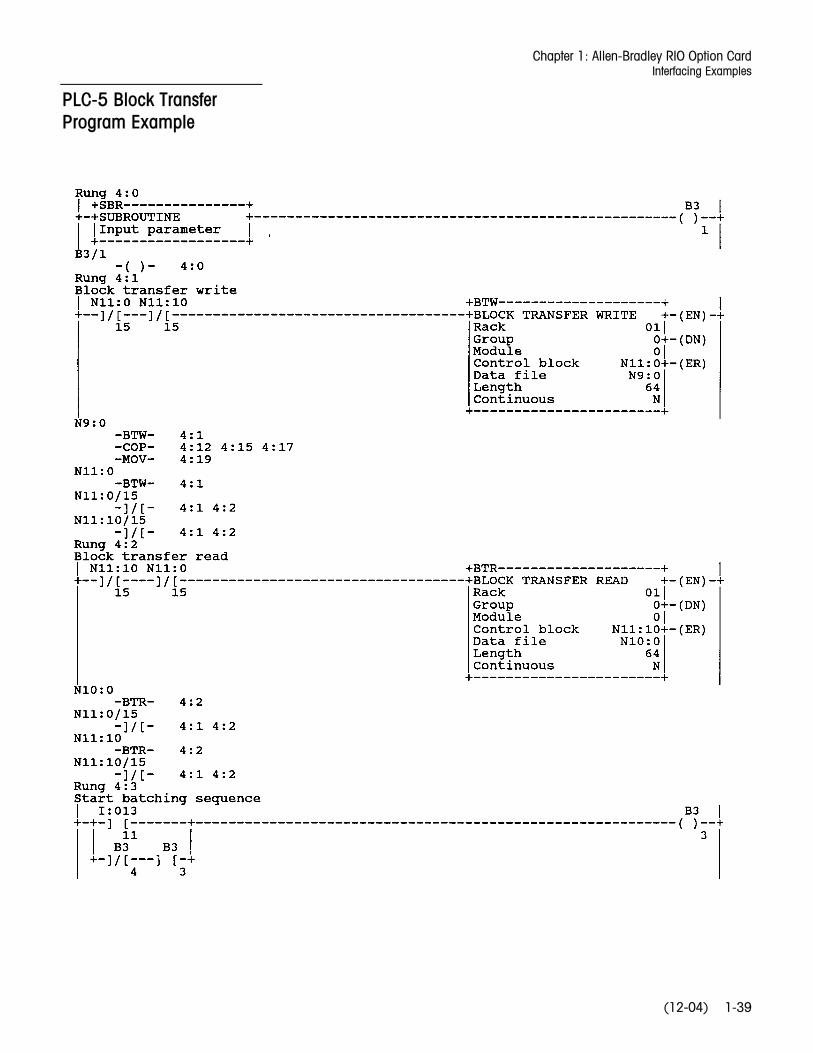
Chapter 1: Allen-Bradley RIO Option Card Interfacing Examples
PLC-5 Block Transfer Program Example
(12-04) 1-39
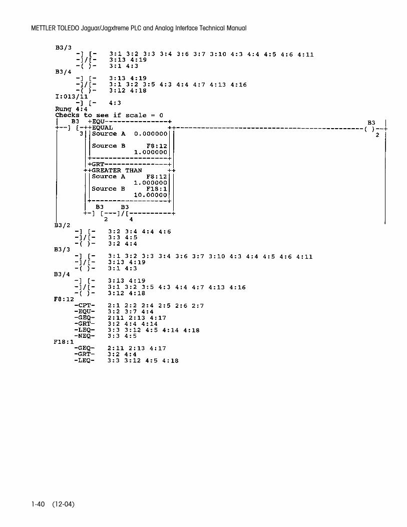
METTLER TOLEDO Jaguar/Jagxtreme PLC and Analog Interface Technical Manual
(12-04) 1-40
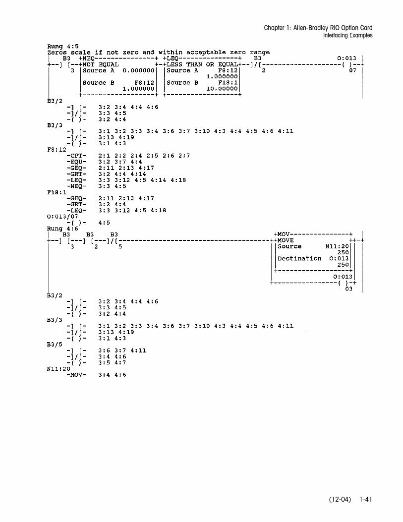
Chapter 1: Allen-Bradley RIO Option Card Interfacing Examples
(12-04) 1-41
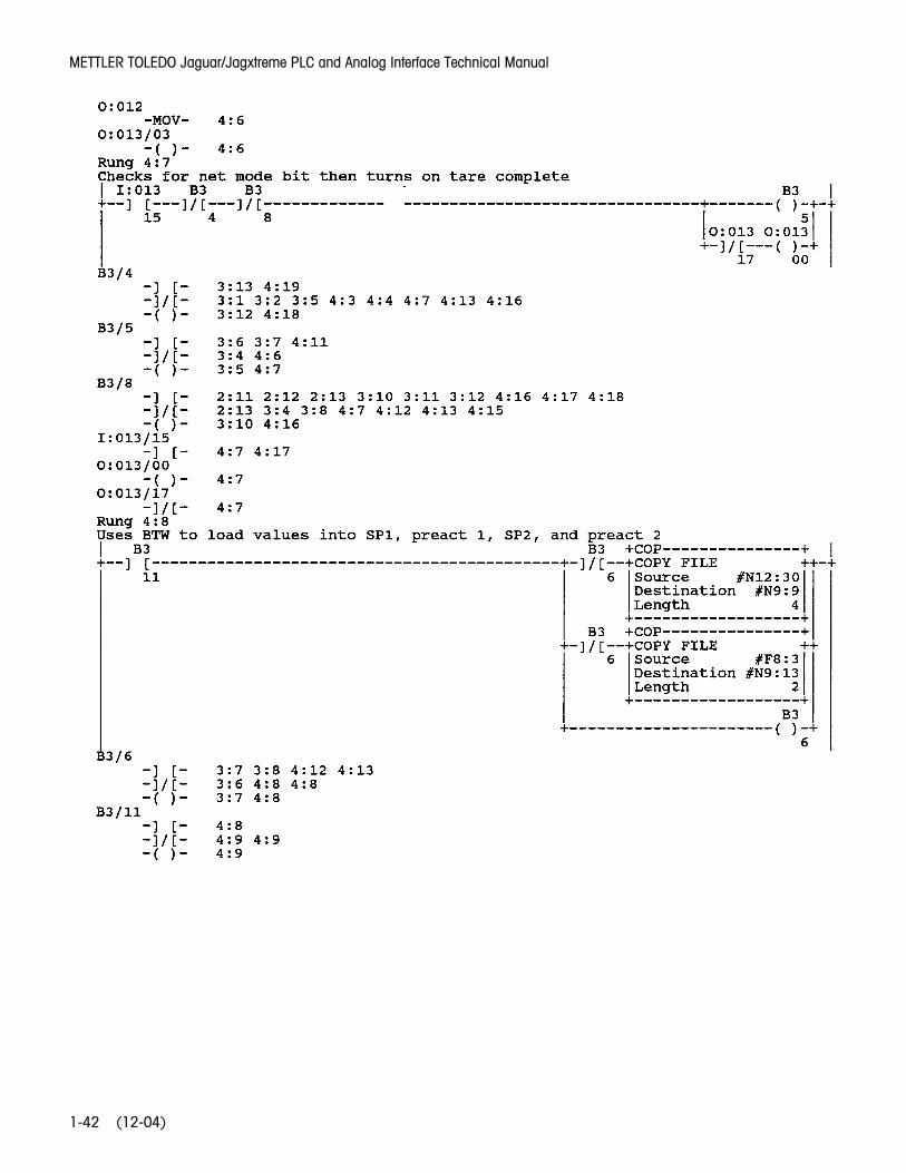
METTLER TOLEDO Jaguar/Jagxtreme PLC and Analog Interface Technical Manual
(12-04) 1-42
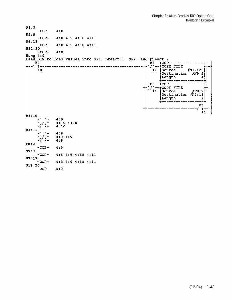
Chapter 1: Allen-Bradley RIO Option Card Interfacing Examples
(12-04) 1-43
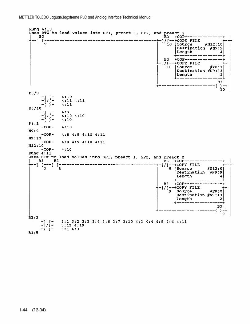
METTLER TOLEDO Jaguar/Jagxtreme PLC and Analog Interface Technical Manual
(12-04) 1-44
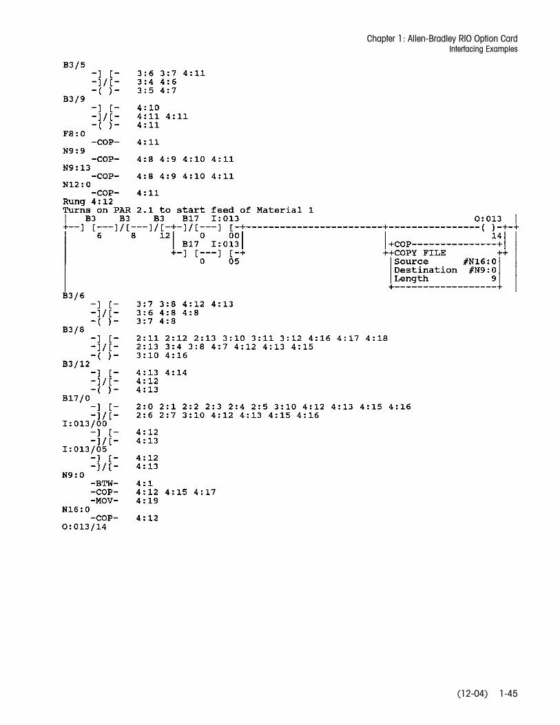
Chapter 1: Allen-Bradley RIO Option Card Interfacing Examples
(12-04) 1-45
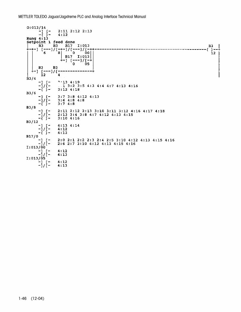
METTLER TOLEDO Jaguar/Jagxtreme PLC and Analog Interface Technical Manual
(12-04) 1-46
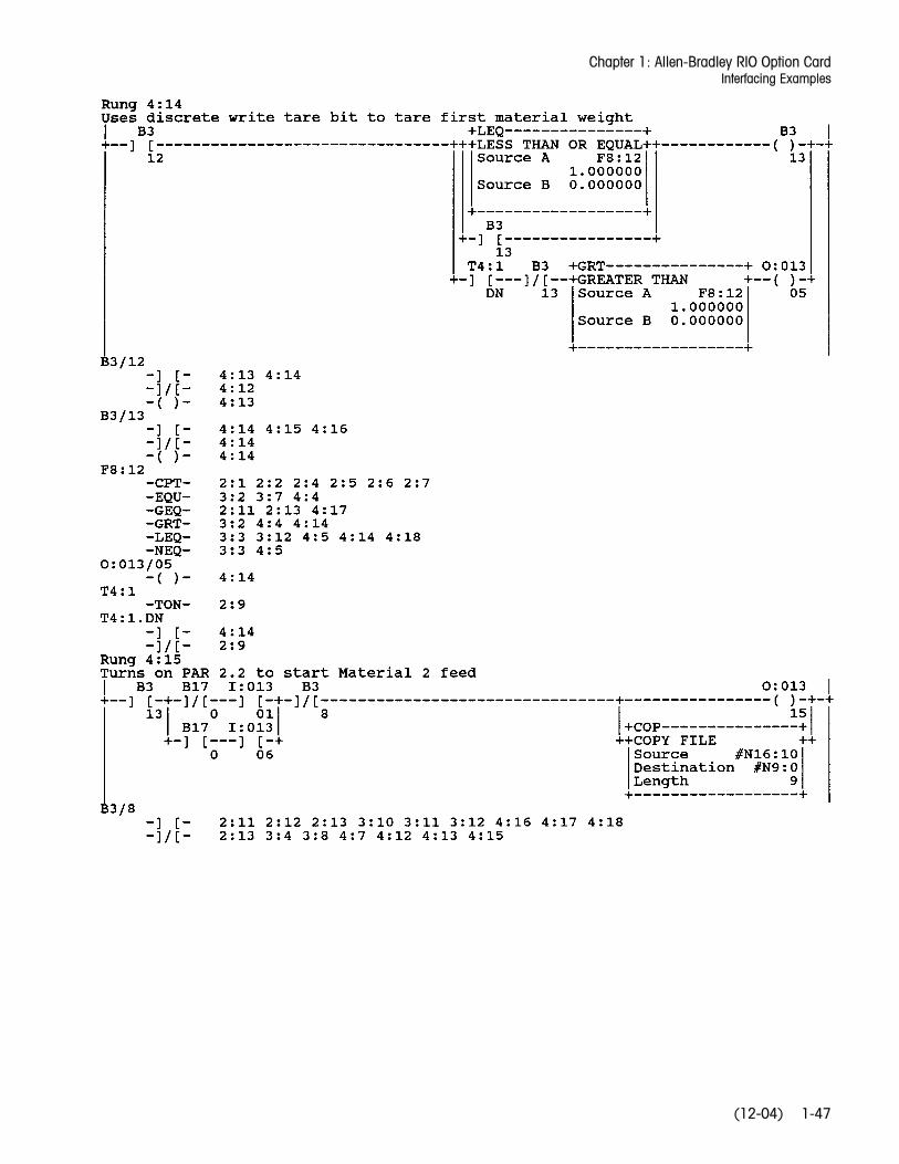
Chapter 1: Allen-Bradley RIO Option Card Interfacing Examples
(12-04) 1-47
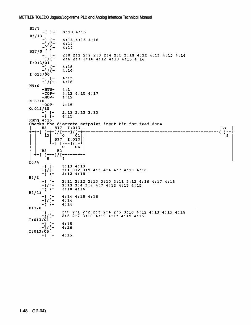
METTLER TOLEDO Jaguar/Jagxtreme PLC and Analog Interface Technical Manual METTLER TOLEDO Jaguar/Jagxtreme PLC and Analog Interface Technical Manual
(12-04) 1-48
(12-04) 1-48
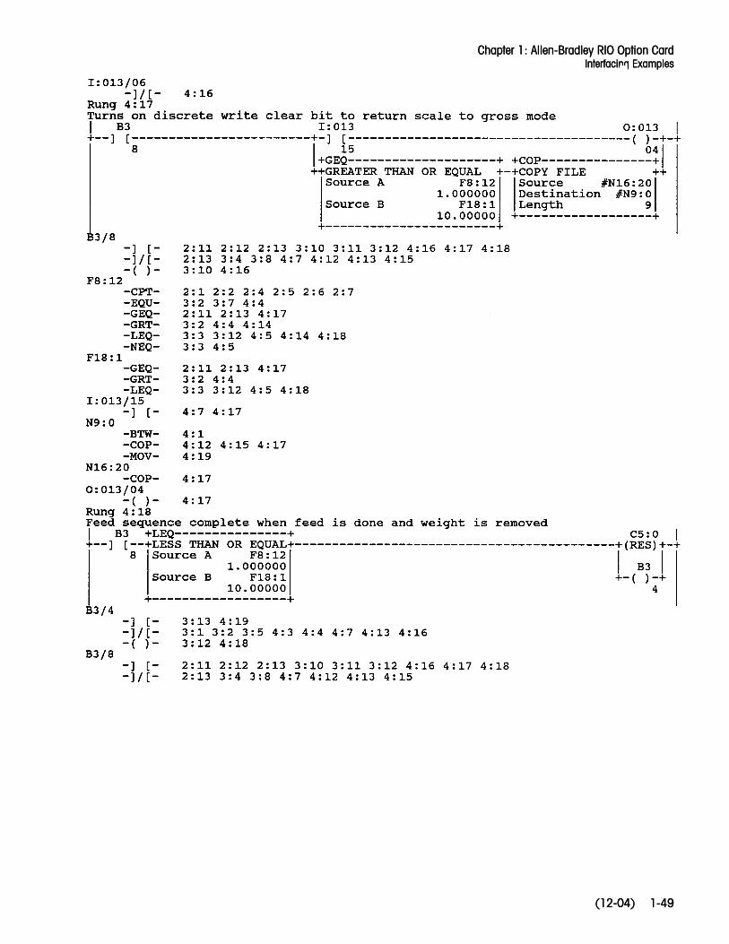
Chapter 1: Allen-Bradley RIO Option Card Interfacing Examples
Chapter 1: Allen-Bradley RIO Option Card Interfacing Examples
(12-04) 1-49
(12-04) 1-49
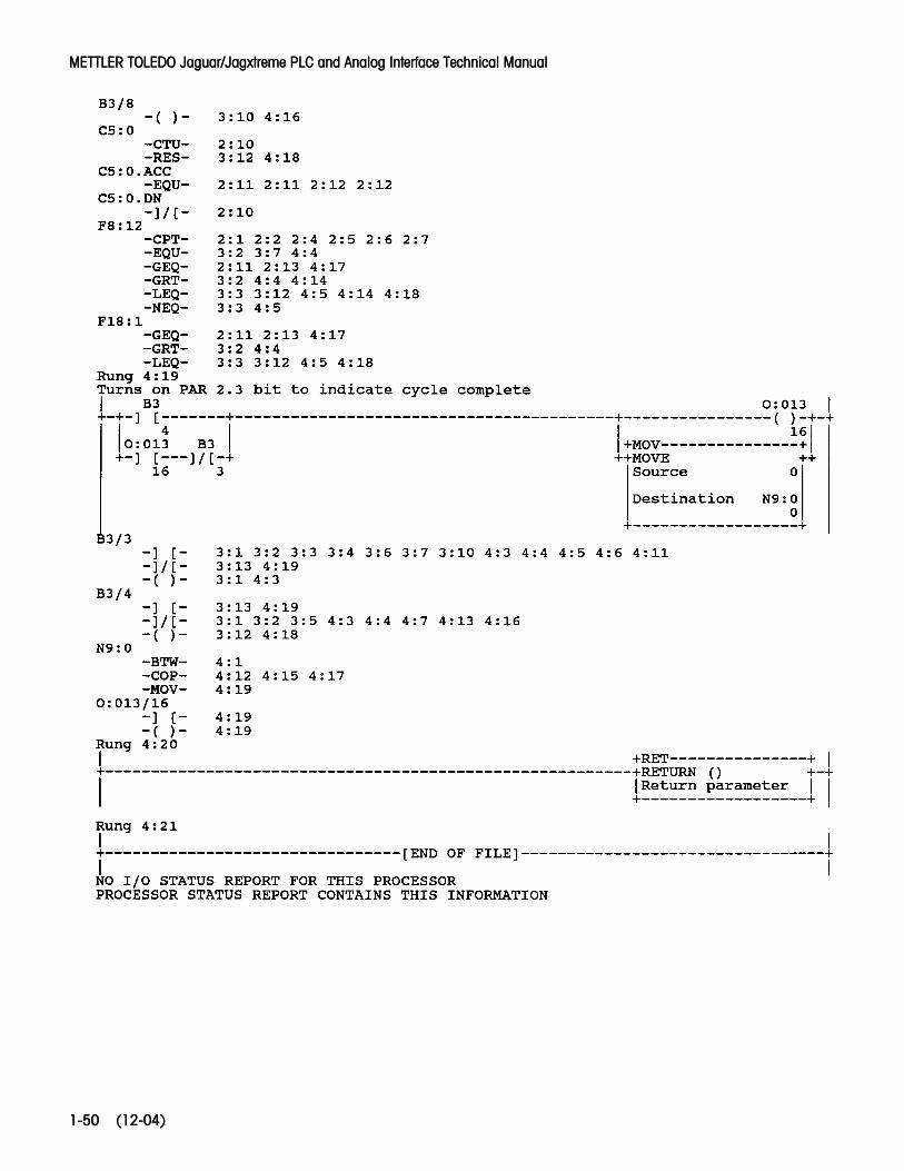
METTLER TOLEDO Jaguar/Jagxtreme PLC and Analog Interface Technical Manual METTLER TOLEDO Jaguar/Jagxtreme PLC and Analog Interface Technical Manual
(12-04) 1-50
(12-04) 1-50
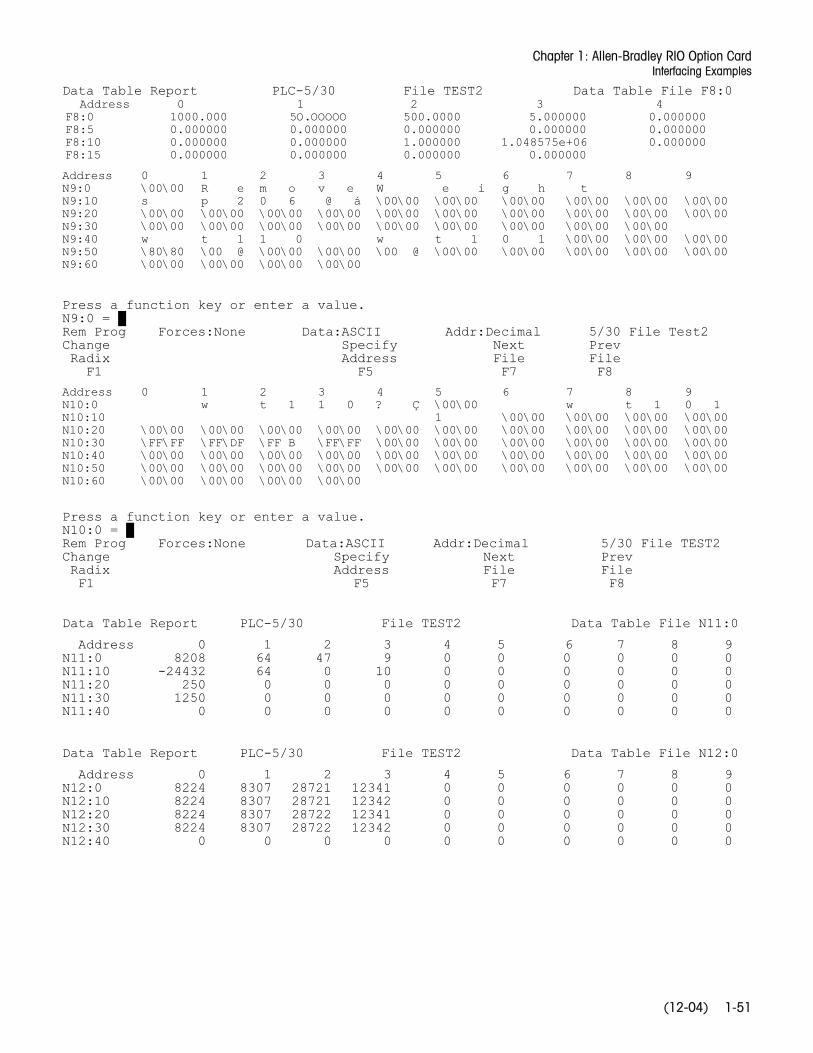
Chapter 1: Allen-Bradley RIO Option Card Interfacing Examples
Data Table Report PLC-5/30 File TEST2 Data Table File F8:0 Address 0 1 2 3 4 F8:0 1000.000 5O.OOOOO 500.0000 5.000000 0.000000 F8:5 0.000000 0.000000 0.000000 0.000000 0.000000 F8:10 0.000000 0.000000 1.000000 1.048575e+06 0.000000 F8:15 0.000000 0.000000 0.000000 0.000000
Address 0 1 2 3 4 5 6 7 8 9 N9:0 \00\00 R e m o v e W e i g h t N9:10 s p 2 0 6 @ á \00\00 \00\00 \00\00 \00\00 \00\00 \00\00 N9:20 \00\00 \00\00 \00\00 \00\00 \00\00 \00\00 \00\00 \00\00 \00\00 \00\00 N9:30 \00\00 \00\00 \00\00 \00\00 \00\00 \00\00 \00\00 \00\00 \00\00 N9:40 w t 1 1 0 w t 1 0 1 \00\00 \00\00 \00\00 N9:50 \80\80 \00 @ \00\00 \00\00 \00 @ \00\00 \00\00 \00\00 \00\00 \00\00 N9:60 \00\00 \00\00 \00\00 \00\00 Press a function key or enter a value. N9:0 = █ Rem Prog Forces:None Data:ASCII Addr:Decimal 5/30 File Test2 Change Specify Next Prev Radix Address File File F1 F5 F7 F8
Address 0 1 2 3 4 5 6 7 8 9 N10:0 w t 1 1 0 ? Ç \00\00 w t 1 0 1 N10:10 1 \00\00 \00\00 \00\00 \00\00 N10:20 \00\00 \00\00 \00\00 \00\00 \00\00 \00\00 \00\00 \00\00 \00\00 \00\00 N10:30 \FF\FF \FF\DF \FF B \FF\FF \00\00 \00\00 \00\00 \00\00 \00\00 \00\00 N10:40 \00\00 \00\00 \00\00 \00\00 \00\00 \00\00 \00\00 \00\00 \00\00 \00\00 N10:50 \00\00 \00\00 \00\00 \00\00 \00\00 \00\00 \00\00 \00\00 \00\00 \00\00 N10:60 \00\00 \00\00 \00\00 \00\00
Press a function key or enter a value. N10:0 = █ Rem Prog Forces:None Data:ASCII Addr:Decimal 5/30 File TEST2 Change Specify Next Prev Radix Address File File F1 F5 F7 F8 Data Table Report PLC-5/30 File TEST2 Data Table File N11:0
Address 0 1 2 3 4 5 6 7 8 9 N11:0 8208 64 47 9 0 0 0 0 0 0 N11:10 -24432 64 0 10 0 0 0 0 0 0 N11:20 250 0 0 0 0 0 0 0 0 0 N11:30 1250 0 0 0 0 0 0 0 0 0 N11:40 0 0 0 0 0 0 0 0 0 0 Data Table Report PLC-5/30 File TEST2 Data Table File N12:0
Address 0 1 2 3 4 5 6 7 8 9 N12:0 8224 8307 28721 12341 0 0 0 0 0 0 N12:10 8224 8307 28721 12342 0 0 0 0 0 0 N12:20 8224 8307 28722 12341 0 0 0 0 0 0 N12:30 8224 8307 28722 12342 0 0 0 0 0 0 N12:40 0 0 0 0 0 0 0 0 0 0
(12-04) 1-51
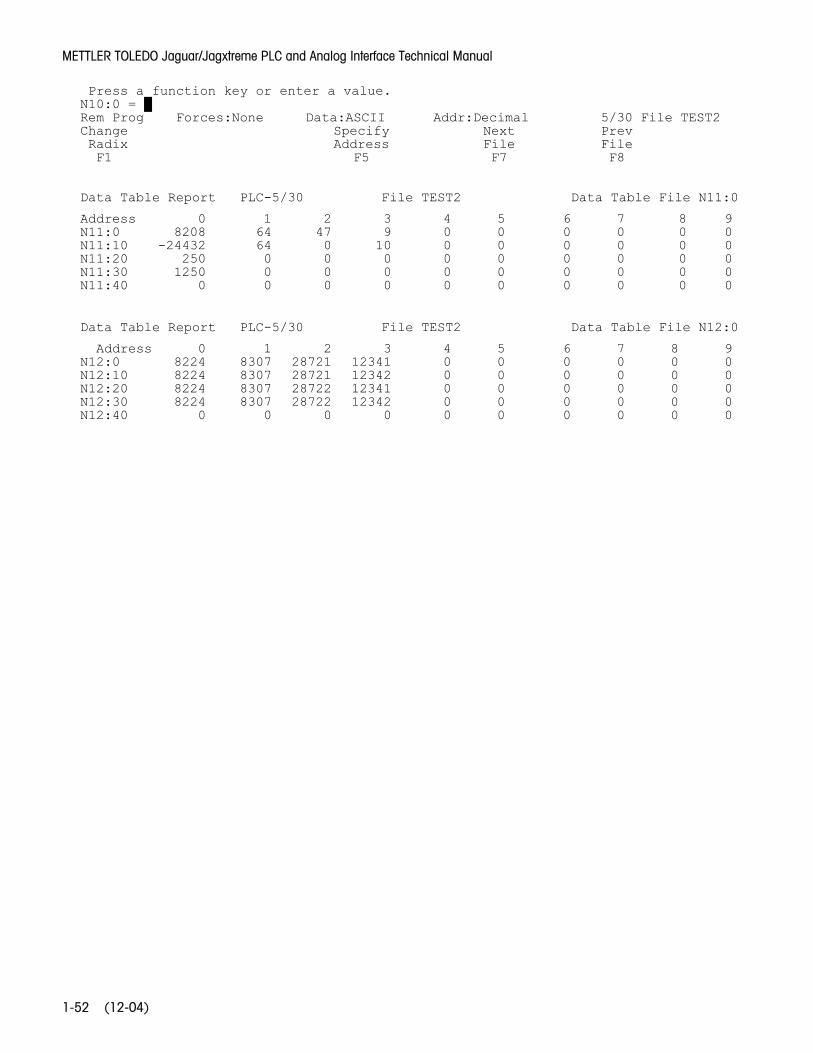
METTLER TOLEDO Jaguar/Jagxtreme PLC and Analog Interface Technical Manual
Press a function key or enter a value. N10:0 = █ Rem Prog Forces:None Data:ASCII Addr:Decimal 5/30 File TEST2 Change Specify Next Prev Radix Address File File F1 F5 F7 F8 Data Table Report PLC-5/30 File TEST2 Data Table File N11:0
Address 0 1 2 3 4 5 6 7 8 9 N11:0 8208 64 47 9 0 0 0 0 0 0 N11:10 -24432 64 0 10 0 0 0 0 0 0 N11:20 250 0 0 0 0 0 0 0 0 0 N11:30 1250 0 0 0 0 0 0 0 0 0 N11:40 0 0 0 0 0 0 0 0 0 0 Data Table Report PLC-5/30 File TEST2 Data Table File N12:0
Address 0 1 2 3 4 5 6 7 8 9 N12:0 8224 8307 28721 12341 0 0 0 0 0 0 N12:10 8224 8307 28721 12342 0 0 0 0 0 0 N12:20 8224 8307 28722 12341 0 0 0 0 0 0 N12:30 8224 8307 28722 12342 0 0 0 0 0 0 N12:40 0 0 0 0 0 0 0 0 0 0
(12-04) 1-52
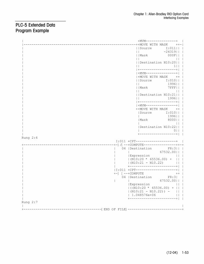
Chapter 1: Allen-Bradley RIO Option Card Interfacing Examples
PLC-5 Extended Data Program Example
| +MVM---------------+ | |--------------------------------------------------------++MOVE WITH MASK ++-| | ||Source I:011|| | | || -24319|| | | ||Mask 000F|| | | || || | | ||Destination N10:20|| | | || 1|| | | |+------------------+| | | |+MVM---------------+| | | |+MOVE WITH MASK ++ | | ||Source I:010|| | | || 1996|| | | ||Mask 7FFF|| | | || || | | ||Destination N10:21|| | | || 1996|| | | |+------------------+| | | |+MVM---------------+| | | ++MOVE WITH MASK ++ | | |Source I:010|| | | | 1996|| | | |Mask 8000|| | | | || | | |Destination N10:22|| | | | 0|| | | +------------------+| | Rung 2:6 I:011 +CPT--------------------+ | +---------------------------------------------+-]/[--+COMPUTE----------------++-+ | | 04 |Destination F8:3|| | | | | 67532.00|| | | | |Expression || | | | |(N10:20 * 65536.00) + || | | | |(N10:21 - N10.22) || | | | +-----------------------+| | | |I:011 +CPT--------------------+| | | +-] [--+COMPUTE ++ | | 04 |Destination F8:3| | | | | 67532.00|| | | |Expression || | | |((N10:20 * 65536.00) + || | | |(N10:21 - N10.22)) - || | | | 1.048576e+06 || | | +-----------------------+| | Rung 2:7 | | +---------------------------------------[END OF FILE]---------------------------+
(12-04) 1-53

METTLER TOLEDO Jaguar/Jagxtreme PLC and Analog Interface Technical Manual
For your notes
(1/03) 1-2
Chapter 2: PROFIBUS Overview
2 PROFIBUS
Overview The PROFIBUS option card enables the JAGXTREME terminal to communicate to a PROFIBUS L2-DP master according to DIN 19 245. It consists of a JAGXTREME terminal backplane-compatible module and software that resides in the terminal, which implements the data exchange.
The PROFIBUS option card interfaces to PLCs such as Texas Instruments 505 series, Siemens S5 series, and Siemens S7 series PLCs.
The Texas Instruments (TI) 505 PLCs interface to the PROFIBUS via an I/O processor called a Field Interface Module (FIM). The FIM bus master recognizes a fixed set of PROFIBUS slave devices, all of which are viewed by it as some sort of remote I/O rack. On power up, the FIM queries each PROFIBUS slave node to determine which of the recognized types a device might be and configures itself accordingly. The PROFIBUS option appears to the FIM to be a small ET200U I/O rack.
The Siemens S5-115 series PLC also interfaces to the PROFIBUS using an I/O processor, an IM-308. This device must be locally programmed with the terminal interface type files. Newer Siemens S7 PLCs have the PROFIBUS option on their main controller card.
Communications PROFIBUS is based on a variety of existing national and international standards. The protocol architecture is based on the Open Systems Interconnection (OSI) reference model in accordance with the international standard ISO 7498.
The JAGXTREME terminal supports the PROFIBUS-DP which is designed for high speed data transfer at the sensor actuator level. (DP means Distributed Peripherals.) At this level, controllers such as programmable logic controllers (PLCs) exchange data via a fast serial link with their distributed peripherals. The data exchange with these distributed devices is mainly cyclic. The central controller (master) reads the input information from the slaves and sends the output information back to the slaves. It is important that the bus cycle time is shorter than the program cycle time of the controller, which is approximately 10 ms in most applications. The following is a summary of the technical features of the PROFIBUS-DP communications protocol:
Transmission Technique: PROFIBUS DIN 19 245 Part 1
-EIA RS 485 twisted pair cable or fiber optic
-9.6 kbit/s up to 12 Mbit/s, max distance 200 m at 1.5 Mbit/s extendible with repeaters
-12 megabaud maximum rate
Medium Access: Hybrid medium access protocol according to DIN 19 245 Part 1
- Mono-Master or Multi-Master systems supported
- Master and Slave Devices, max 126 stations possible
(12/04) 2-1
JAGXTREME PLC and ANALOG OUTPUT INTERFACE Technical Manual
Communications: Peer-to-Peer (user data transfer) or Multicast (synchronization)
- Cyclic Master-Slave user data transfer and acyclic Master-Master data transfer.
Operation Modes:
- Operate: Cyclic transfer of input and output data
- Clear: Inputs are read and outputs are cleared
- Stop: Only master-master functions are possible
Synchronization: enables synchronization of the inputs and/or outputs of all DP-Slaves
- Sync-Mode: Outputs are synchronized
- Freeze-Mode: Inputs are synchronized
Functionality:
- Cyclic user data transfer between DP-Master(s) and DP-Slave(s)
- Activation or deactivation of individual DP-Slaves
- Checking of the configuration of the DP-Slaves
- Powerful diagnosis mechanisms, 3 hierarchical levels of the diagnosis
- Synchronization of inputs and/or outputs
- Address assignment for the DP-Slaves over the bus
- Configuration of the DP-Master (DPM1) over the bus
- Max. 246 byte input and output data per DP-Slave, typical 32 byte
Security and Protection Mechanisms:
- All messages are transmitted with Hamming Distance HD=4
- Watch-Dog Timer at the DP-Slaves
- Access protection for the inputs/outputs at the DP-Slaves
- Data transfer monitoring with configurable timer interval at the DP-Master (DPM1)
Device-Types:
- DP-Master Class 2 (DPM2) e.g. programming/configuration device
- DP-Master Class 1 (DPM1) e.g. central controller like PLC, CNC, or RC
- DP-Slave e.g. Input/Output device with binary or analogue inputs/outputs, drives.
Cabling and Installation:
- Coupling or uncoupling of stations without affecting other stations
- Proven and easy to handle two conductor transmission technique
(12/04) 2-2
Chapter 2: PROFIBUS Overview
Node/Rack Address Each PROFIBUS option card represents one physical node but may contain data for multiple scales. The node address is chosen by the system designer, then programmed into the terminal and PLC. The terminal’s node address is programmed through the Configure Options PROFIBUS program block in the setup menu. The node address and amount of input and output words used to communicate between the terminal and the PLC are programmed into the PLC by using its PROFIBUS network configuration software and the terminal’s PROFIBUS type files.
The type file used is dependent on the data format and number of scales selected in the terminal. The terminal setup capabilities allow selection of the logical rack (node) address, data format, and number of scales using the node. The terminal will determine the number of input and output words needed for the number of configured scales and chosen data format. The PLC must be configured for the same amount of space.
Data Formats The terminal’s PROFIBUS option card has two types of data exchanges: discrete data and shared data. Each scale selected to pass data through the terminal’s PROFIBUS option has its own assigned input and output words for continuous information to and from the PLC. Shared data access is only available when four scales have been configured. This data is used to pass information that cannot be sent in the discrete data because of size or process speed limitations. It uses additional input and output word space.
Remote Scale Sharing Using Ethernet makes it possible for JAGXTREME terminals to communicate with each other and to share resources. A JAGXTREME terminal with a PROFIBUS option card can collect information from up to four networked and local scales when using any of its data formats. The following charts show possible configurations with and without resource sharing.
(12/04) 2-3
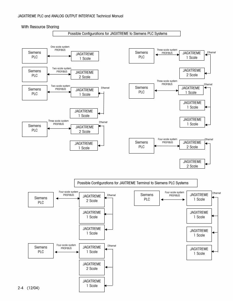
JAGXTREME PLC and ANALOG OUTPUT INTERFACE Technical Manual
Possible Configurations for JAGXTREME to Siemens PLC Systems
(12/04) 2-4
Three-scale system PROFIBUS
Three-scale system PROFIBUS
Four-scale system PROFIBUS
Siemens PLC
JAGXTREME 1 Scale
JAGXTREME 2 Scale
JAGXTREME 1 Scale
JAGXTREME 1 Scale
Siemens PLC
JAGXTREME 1 Scale
JAGXTREME 2 Scale
Ethernet
Ethernet
Ethernet
JAGXTREME 2 Scale
Siemens PLC
Ethernet
Ethernet
One-scale system PROFIBUS
Two-scale system PROFIBUS
Three-scale system PROFIBUS
JAGXTREME 1 Scale
Siemens PLC
Siemens PLC
JAGXTREME 1 Scale
JAGXTREME 2 Scale
Siemens PLC
JAGXTREME 2 Scale
Two-scale system PROFIBUS
JAGXTREME 1 Scale
JAGXTREME 1 Scale
Siemens PLC
Possible Configurations for JAXTREME Terminal to Siemens PLC Systems
Ethernet Four-scale system PROFIBUS
Four-scale system PROFIBUS Siemens
PLC JAGXTREME
1 Scale
JAGXTREME 1 Scale
JAGXTREME 1 Scale
JAGXTREME 1 Scale
JAGXTREME 1 Scale
JAGXTREME 2 Scale
JAGXTREME 1 Scale
JAGXTREME 2 Scale
JAGXTREME 1 Scale
JAGXTREME 1 Scale
EthernetFour-scale system PROFIBUS
Siemens PLC
Siemens PLC
Ethernet
With Resource Sharing
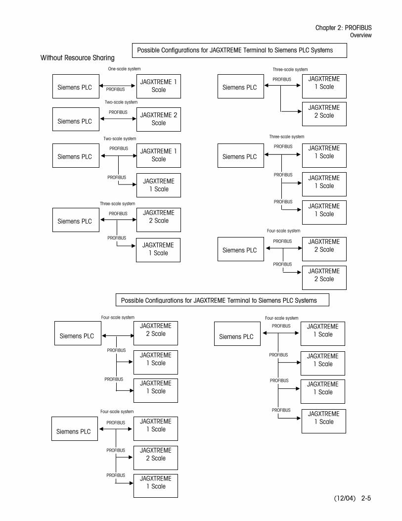
Chapter 2: PROFIBUS Overview
WPossible Configurations for JAGXTREME Terminal to Siemens PLC Systems
ithout Resource Sharing
(12/04) 2-5
PROFIBUS
Four-scale system
Siemens PLC
JAGXTREME 1 Scale
Four-scale system
JAGXTREME 2 Scale
JAGXTREME 1 Scale
JAGXTREME 1 Scale
Siemens PLC
JAGXTREME 2 Scale
JAGXTREME 1 Scale
JAGXTREME 1 Scale
Four-scale system
PROFIBUS
PROFIBUS
PROFIBUS
PROFIBUS
PROFIBUS
PROFIBUS
PROFIBUS
PROFIBUS JAGXTREME
1 Scale
JAGXTREME 1 Scale
JAGXTREME 1 Scale
Siemens PLC
Possible Configurations for JAGXTREME Terminal to Siemens PLC Systems
PROFIBUS
Three-scale system One-scale system
Siemens PLC
JAGXTREME 2 Scale
JAGXTREME 1 Scale
Siemens PLC
JAGXTREME 1 Scale
JAGXTREME 1 Scale
JAGXTREME 1 Scale
Three-scale system
PROFIBUS Siemens PLC
JAGXTREME 1 Scale
Two-scale system
Siemens PLC
JAGXTREME 2 Scale
Siemens PLC
JAGXTREME 1 Scale
JAGXTREME 1 Scale
JAGXTREME 1 Scale
Siemens PLC
JAGXTREME 2 Scale
Two-scale system
Three-scale system
Siemens PLC
JAGXTREME 2 Scale
JAGXTREME 2 Scale
Four-scale system
PROFIBUS
PROFIBUS
PROFIBUS
PROFIBUS
PROFIBUS
PROFIBUS
PROFIBUS
PROFIBUS
PROFIBUS
PROFIBUS
JAGXTREME PLC and ANALOG OUTPUT INTERFACE Technical Manual
Data Definition The PROFIBUS option card uses two types of data for communicating with the PLC: discrete data and shared data. Separate discrete data for each scale is always available and the data transfer is accomplished via the PLC’s PROFIBUS network communication messaging. Shared data is only available if data for four scales are enabled through the terminal setup menu. If the shared data is used, it is provided IN ADDITION TO the discrete data for each scale.
Data Integrity The terminal has specific bits to allow the PLC to confirm that the data was received without interrupt, and the scale is not in an error condition. It is important to monitor these bits. Any PLC code should use them to confirm the integrity of the data received for the scale. Refer to the detailed data charts for specific information regarding the Data OK, update in progress, and data integrity bits and their usage.
Discrete Data There are four formats of discrete data available with the PROFIBUS option card: integer (wgt), division (div), extended integer (ext), and floating point (flt). Only one data format may be selected and used by scales sharing the same PROFIBUS option card.
The integer and division formats allow bi-directional communication of discrete bit encoded information or 16-bit binary word (signed integer) numerical values. The extended integer format allows bi-directional communication of discrete bit encoded information, 21-bit binary word (signed extended integer) numerical read values or 16-bit binary word (signed integer) numerical write values.
The floating point format allows bi-directional communication of discrete bit encoded information or numeric data encoded in IEEE 754, single precision floating point format.
The discrete data format affects the input/output word space required per scale and the amount of input/output words used by the PROFIBUS option card. Integer, division, and extended integer formats require two 16-bit words of input and two 16-bit words of output data per scale. One scale uses two 16-bit words of input and two 16-bit words of output; two scales use four16-bit words of input and four 16-bit words of output; three scales use six 16-bit words of input and six 16-bit words of output; and four scales use eight 16-bit words of input and eight 16-bit words of output.
The floating point format requires more space per scale because floating point data uses two 16-bit words of data to represent the numeric data alone. The floating point format requires four 16-bit words of input and four 16-bit words of output data per scale. The smallest amount that the terminal can configure for floating point is eight words of input / eight words of output. This means that when a single scale is configured, there are two sets of input/output data for the scale. Four scales using the floating point format would use 16 words of input and 16 words of output data. Shared data would require additional space.
Selection of the appropriate format depends on different issues. The range or capacity of the scale used in the application should be considered. The integer format can represent a numerical value of up to 32,767; the division format can represent a numerical value of up to 32,767 divisions (or increments); the extended integer can represent a numerical value of over 1,000,000; and, the floating point format can represent a numerical value encoded in IEEE 754, single precision floating point format.
(12/04) 2-6
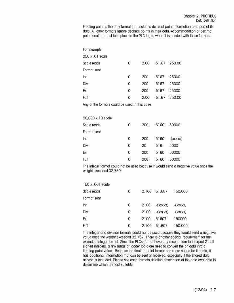
Chapter 2: PROFIBUS Data Definition
Floating point is the only format that includes decimal point information as a part of its data. All other formats ignore decimal points in their data. Accommodation of decimal point location must take place in the PLC logic, when it is needed with these formats.
For example:
250 x .01 scale
Scale reads: 0 2.00 51.67 250.00
Format sent:
Int 0 200 5167 25000
Div 0 200 5167 25000
Ext 0 200 5167 25000
FLT 0 2.00 51.67 250.00
Any of the formats could be used in this case
50,000 x 10 scale
Scale reads: 0 200 5160 50000
Format sent:
Int 0 200 5160 -(xxxxx)
Div 0 20 516 5000
Ext 0 200 5160 50000
FLT 0 200 5160 50000
The integer format could not be used because it would send a negative value once the weight exceeded 32,760.
150 x .001 scale
Scale reads: 0 2.100 51.607 150.000
Format sent:
Int 0 2100 -(xxxxx) -(xxxxx)
Div 0 2100 -(xxxxx) -(xxxxx)
Ext 0 2100 51607 150000
FLT 0 2.100 51.607 150.000
The integer and division formats could not be used because they would send a negative value once the weight exceeded 32.767. There is another special requirement for the extended integer format. Since the PLCs do not have any mechanism to interpret 21-bit signed integers, a few rungs of ladder logic are need to convert the bit data into a floating point value. Because the floating point format has more space for its data, it has additional information that can be sent or received, especially if the shared data access is included. Please see each formats detailed description of the data available to determine which is most suitable.
(12/04) 2-7
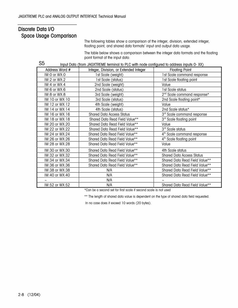
JAGXTREME PLC and ANALOG OUTPUT INTERFACE Technical Manual
Discrete Data I/O Space Usage Comparison
The following tables show a comparison of the integer, division, extended integer, floating point, and shared data formats’ input and output data usage.
The table below shows a comparison between the integer data formats and the floating point format of the input data:
Input Data (from JAGXTREME terminal to PLC with node configured to address inputs 0- XX) Address Word # Integer, Division, or Extended Integer Floating Point IW:0 or WX:0 1st Scale (weight) 1st Scale command response IW:2 or WX:2 1st Scale (status) 1st Scale floating point IW:4 or WX:4 2nd Scale (weight) Value IW:6 or WX:6 2nd Scale (status) 1st Scale status IW:8 or WX:8 3rd Scale (weight) 2nd Scale command response* IW:10 or WX:10 3rd Scale (status) 2nd Scale floating point* IW:12 or WX:12 4th Scale (weight) Value IW:14 or WX:14 4th Scale (status) 2nd Scale status* IW:16 or WX:16 Shared Data Access Status 3rd Scale command response IW:18 or WX:18 Shared Data Read Field Value** 3rd Scale floating point IW:20 or WX:20 Shared Data Read Field Value** Value IW:22 or WX:22 Shared Data Read Field Value** 3rd Scale status IW:24 or WX:24 Shared Data Read Field Value** 4th Scale command response IW:26 or WX:26 Shared Data Read Field Value** 4th Scale floating point IW:28 or WX:28 Shared Data Read Field Value** Value
IW:30 or WX:30 Shared Data Read Field Value** 4th Scale status IW:32 or WX:32 Shared Data Read Field Value** Shared Data Access Status IW:34 or WX:34 Shared Data Read Field Value** Shared Data Read Field Value** IW:36 or WX:36 Shared Data Read Field Value** Shared Data Read Field Value** IW:38 or WX:38 N/A Shared Data Read Field Value** IW:40 or WX:40 N/A Shared Data Read Field Value** ~ N/A ~ IW:52 or WX:52 N/A Shared Data Read Field Value**
S5
*Can be a second set for first scale if second scale is not used
** The length of shared data value is dependent on the type of shared data field requested.
In no case does it exceed 10 words (20 bytes).
(12/04) 2-8
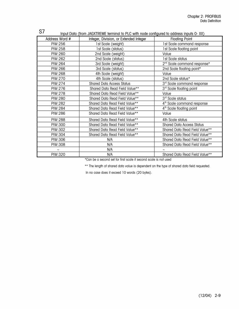
Chapter 2: PROFIBUS Data Definition
S7 Input Data (from JAGXTREME terminal to PLC with node configured to address inputs 0- XX) Address Word # Integer, Division, or Extended Integer Floating Point
PIW:256 1st Scale (weight) 1st Scale command response PIW:258 1st Scale (status) 1st Scale floating point PIW:260 2nd Scale (weight) Value PIW:262 2nd Scale (status) 1st Scale status PIW:264 3rd Scale (weight) 2nd Scale command response* PIW:266 3rd Scale (status) 2nd Scale floating point* PIW:268 4th Scale (weight) Value PIW:270 4th Scale (status) 2nd Scale status* PIW:274 Shared Data Access Status 3rd Scale command response PIW:276 Shared Data Read Field Value** 3rd Scale floating point PIW:278 Shared Data Read Field Value** Value PIW:280 Shared Data Read Field Value** 3rd Scale status PIW:282 Shared Data Read Field Value** 4th Scale command response PIW:284 Shared Data Read Field Value** 4th Scale floating point PIW:286 Shared Data Read Field Value** Value
PIW:288 Shared Data Read Field Value** 4th Scale status PIW:300 Shared Data Read Field Value** Shared Data Access Status PIW:302 Shared Data Read Field Value** Shared Data Read Field Value** PIW:304 Shared Data Read Field Value** Shared Data Read Field Value** PIW:306 N/A Shared Data Read Field Value** PIW:308 N/A Shared Data Read Field Value**
~ N/A ~ PIW:320 N/A Shared Data Read Field Value**
*Can be a second set for first scale if second scale is not used
** The length of shared data value is dependent on the type of shared data field requested.
In no case does it exceed 10 words (20 bytes).
(12/04) 2-9
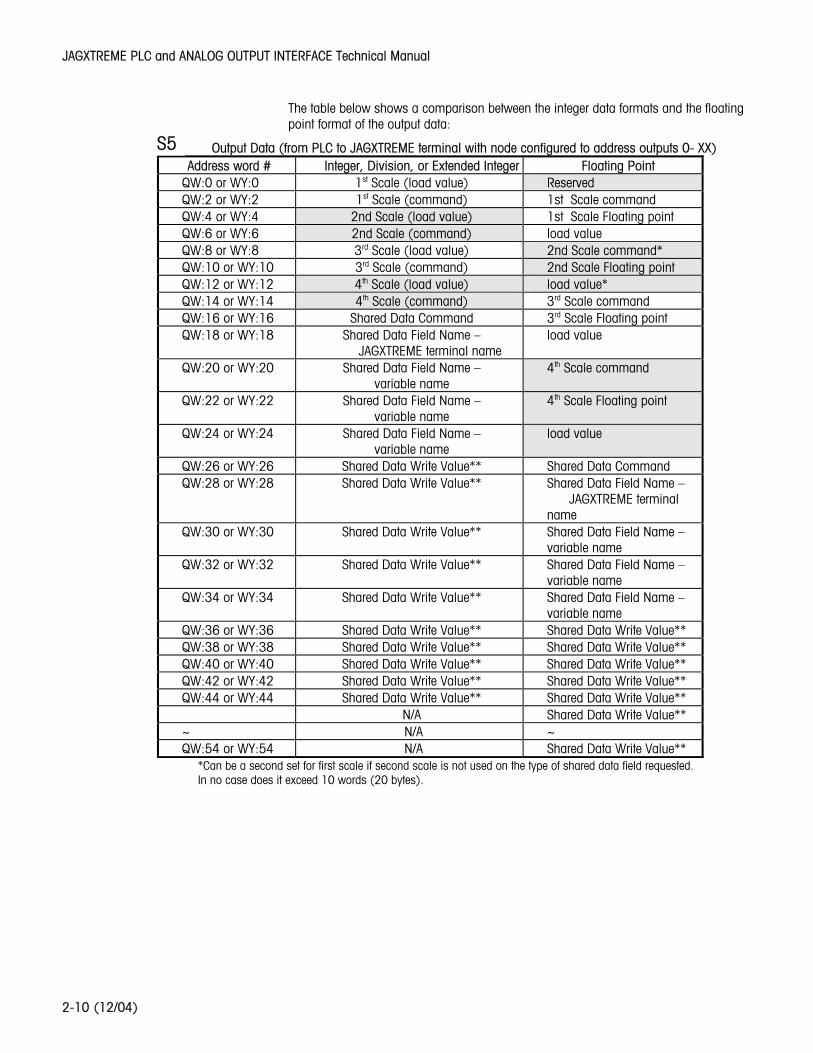
JAGXTREME PLC and ANALOG OUTPUT INTERFACE Technical Manual
The table below shows a comparison between the integer data formats and the floating point format of the output data:
Output Data (from PLC to JAGXTREME terminal with node configured to address outputs 0- XX) Address word # Integer, Division, or Extended Integer Floating Point
QW:0 or WY:0 1st Scale (load value) Reserved QW:2 or WY:2 1st Scale (command) 1st Scale command QW:4 or WY:4 2nd Scale (load value) 1st Scale Floating point QW:6 or WY:6 2nd Scale (command) load value QW:8 or WY:8 3rd Scale (load value) 2nd Scale command* QW:10 or WY:10 3rd Scale (command) 2nd Scale Floating point QW:12 or WY:12 4th Scale (load value) load value* QW:14 or WY:14 4th Scale (command) 3rd Scale command QW:16 or WY:16 Shared Data Command 3rd Scale Floating point QW:18 or WY:18 Shared Data Field Name –
JAGXTREME terminal name load value
QW:20 or WY:20 Shared Data Field Name – variable name
4th Scale command
QW:22 or WY:22 Shared Data Field Name – variable name
4th Scale Floating point
QW:24 or WY:24 Shared Data Field Name – variable name
load value
QW:26 or WY:26 Shared Data Write Value** Shared Data Command QW:28 or WY:28 Shared Data Write Value** Shared Data Field Name –
JAGXTREME terminal name
QW:30 or WY:30 Shared Data Write Value** Shared Data Field Name – variable name
QW:32 or WY:32 Shared Data Write Value** Shared Data Field Name – variable name
QW:34 or WY:34 Shared Data Write Value** Shared Data Field Name – variable name
QW:36 or WY:36 Shared Data Write Value** Shared Data Write Value** QW:38 or WY:38 Shared Data Write Value** Shared Data Write Value** QW:40 or WY:40 Shared Data Write Value** Shared Data Write Value** QW:42 or WY:42 Shared Data Write Value** Shared Data Write Value** QW:44 or WY:44 Shared Data Write Value** Shared Data Write Value** N/A Shared Data Write Value** ~ N/A ~ QW:54 or WY:54 N/A Shared Data Write Value**
S5
*Can be a second set for first scale if second scale is not used on the type of shared data field requested. In no case does it exceed 10 words (20 bytes).
(12/04) 2-10
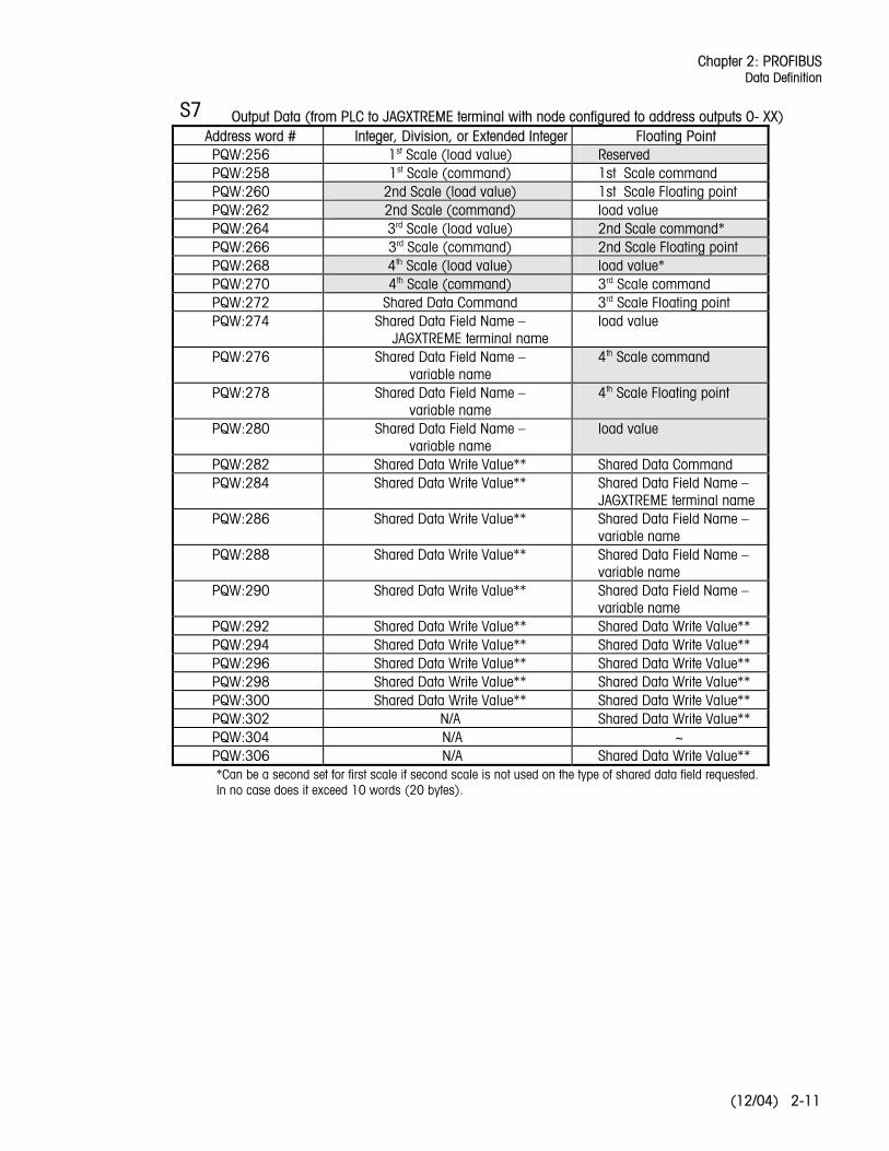
Chapter 2: PROFIBUS Data Definition
S7 Output Data (from PLC to JAGXTREME terminal with node configured to address outputs 0- XX)
Address word # Integer, Division, or Extended Integer Floating Point PQW:256 1st Scale (load value) Reserved PQW:258 1st Scale (command) 1st Scale command PQW:260 2nd Scale (load value) 1st Scale Floating point PQW:262 2nd Scale (command) load value PQW:264 3rd Scale (load value) 2nd Scale command* PQW:266 3rd Scale (command) 2nd Scale Floating point PQW:268 4th Scale (load value) load value* PQW:270 4th Scale (command) 3rd Scale command PQW:272 Shared Data Command 3rd Scale Floating point PQW:274 Shared Data Field Name –
JAGXTREME terminal name load value
PQW:276 Shared Data Field Name – variable name
4th Scale command
PQW:278 Shared Data Field Name – variable name
4th Scale Floating point
PQW:280 Shared Data Field Name – variable name
load value
PQW:282 Shared Data Write Value** Shared Data Command PQW:284 Shared Data Write Value** Shared Data Field Name –
JAGXTREME terminal name PQW:286 Shared Data Write Value** Shared Data Field Name –
variable name PQW:288 Shared Data Write Value** Shared Data Field Name –
variable name PQW:290 Shared Data Write Value** Shared Data Field Name –
variable name PQW:292 Shared Data Write Value** Shared Data Write Value** PQW:294 Shared Data Write Value** Shared Data Write Value** PQW:296 Shared Data Write Value** Shared Data Write Value** PQW:298 Shared Data Write Value** Shared Data Write Value** PQW:300 Shared Data Write Value** Shared Data Write Value** PQW:302 N/A Shared Data Write Value** PQW:304 N/A ~ PQW:306 N/A Shared Data Write Value** *Can be a second set for first scale if second scale is not used on the type of shared data field requested. In no case does it exceed 10 words (20 bytes).
(12/04) 2-11
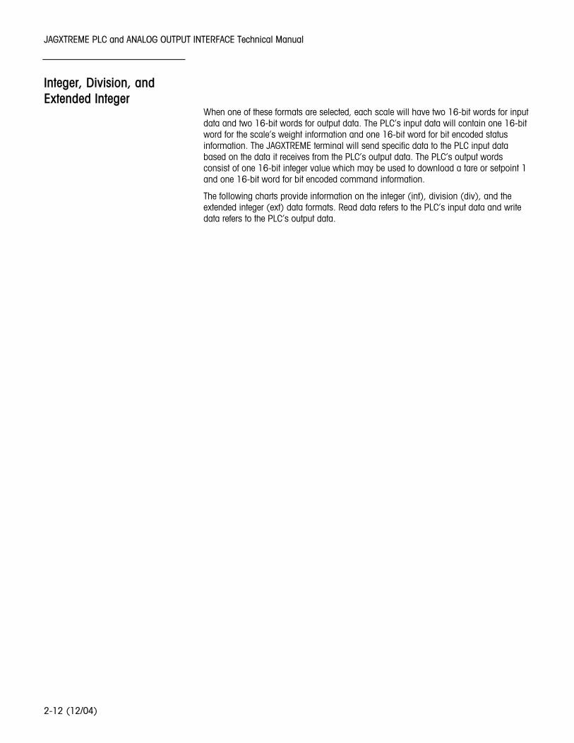
JAGXTREME PLC and ANALOG OUTPUT INTERFACE Technical Manual
2-12 (12/04)
Integer, Division, and Extended Integer
When one of these formats are selected, each scale will have two 16-bit words for input data and two 16-bit words for output data. The PLC’s input data will contain one 16-bit word for the scale’s weight information and one 16-bit word for bit encoded status information. The JAGXTREME terminal will send specific data to the PLC input data based on the data it receives from the PLC’s output data. The PLC’s output words consist of one 16-bit integer value which may be used to download a tare or setpoint 1 and one 16-bit word for bit encoded command information.
The following charts provide information on the integer (int), division (div), and the extended integer (ext) data formats. Read data refers to the PLC’s input data and write data refers to the PLC’s output data.
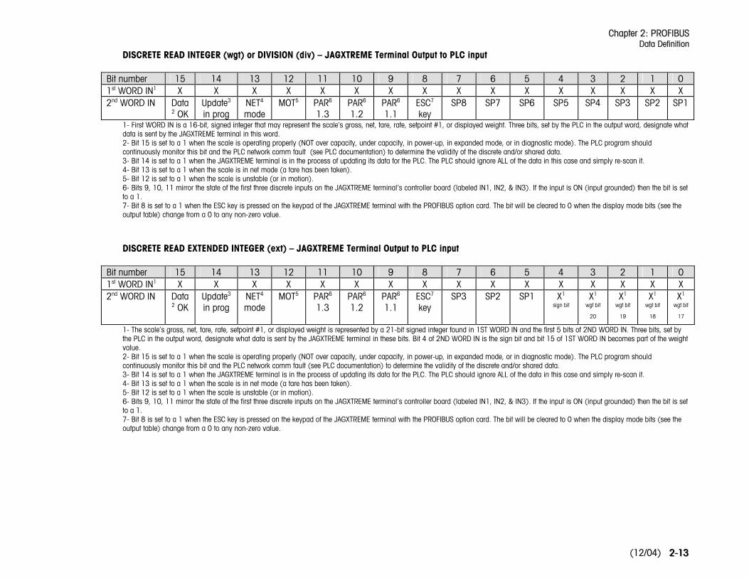
Chapter 2: PROFIBUS Data Definition
DISCRETE READ INTEGER (wgt) or DIVISION (div) – JAGXTREME Terminal Output to PLC input
Bit number 15 14 13 12 11 10 9 8 7 6 5 4 3 2 1 0 1st WORD IN1 X X X X X X X X X X X X X X X X2nd WORD IN
Data2 OK
Update3 in prog
NET4 mode
MOT5 PAR6 1.3
PAR6 1.2
PAR6 1.1
ESC7
key SP8 SP7 SP6 SP5 SP4 SP3 SP2 SP1
1- First WORD IN is a 16-bit, signed integer that may represent the scale’s gross, net, tare, rate, setpoint #1, or displayed weight. Three bits, set by the PLC in the output word, designate what data is sent by the JAGXTREME terminal in this word. 2- Bit 15 is set to a 1 when the scale is operating properly (NOT over capacity, under capacity, in power-up, in expanded mode, or in diagnostic mode). The PLC program should continuously monitor this bit and the PLC network comm fault (see PLC documentation) to determine the validity of the discrete and/or shared data. 3- Bit 14 is set to a 1 when the JAGXTREME terminal is in the process of updating its data for the PLC. The PLC should ignore ALL of the data in this case and simply re-scan it. 4- Bit 13 is set to a 1 when the scale is in net mode (a tare has been taken). 5- Bit 12 is set to a 1 when the scale is unstable (or in motion). 6- Bits 9, 10, 11 mirror the state of the first three discrete inputs on the JAGXTREME terminal’s controller board (labeled IN1, IN2, & IN3). If the input is ON (input grounded) then the bit is set to a 1. 7- Bit 8 is set to a 1 when the ESC key is pressed on the keypad of the JAGXTREME terminal with the PROFIBUS option card. The bit will be cleared to 0 when the display mode bits (see the output table) change from a 0 to any non-zero value. DISCRETE READ EXTENDED INTEGER (ext) – JAGXTREME Terminal Output to PLC input
Bit number 15 14 13 12 11 10 9 8 7 6 5 4 3 2 1 0 1st WORD IN1 X X X X X X X X X X X X X X X X2nd WORD IN Data
2 OK Update3 in prog
NET4 mode
MOT5 PAR6 1.3
PAR6 1.2
PAR6 1.1
ESC7
key SP3 SP2 SP1 X1
sign bitX1
wgt bit
20
X1
wgt bit
19
X1
wgt bit
18
X1
wgt bit
17
1- The scale’s gross, net, tare, rate, setpoint #1, or displayed weight is represented by a 21-bit signed integer found in 1ST WORD IN and the first 5 bits of 2ND WORD IN. Three bits, set by the PLC in the output word, designate what data is sent by the JAGXTREME terminal in these bits. Bit 4 of 2ND WORD IN is the sign bit and bit 15 of 1ST WORD IN becomes part of the weight value. 2- Bit 15 is set to a 1 when the scale is operating properly (NOT over capacity, under capacity, in power-up, in expanded mode, or in diagnostic mode). The PLC program should continuously monitor this bit and the PLC network comm fault (see PLC documentation) to determine the validity of the discrete and/or shared data. 3- Bit 14 is set to a 1 when the JAGXTREME terminal is in the process of updating its data for the PLC. The PLC should ignore ALL of the data in this case and simply re-scan it. 4- Bit 13 is set to a 1 when the scale is in net mode (a tare has been taken). 5- Bit 12 is set to a 1 when the scale is unstable (or in motion). 6- Bits 9, 10, 11 mirror the state of the first three discrete inputs on the JAGXTREME terminal’s controller board (labeled IN1, IN2, & IN3). If the input is ON (input grounded) then the bit is set to a 1. 7- Bit 8 is set to a 1 when the ESC key is pressed on the keypad of the JAGXTREME terminal with the PROFIBUS option card. The bit will be cleared to 0 when the display mode bits (see the output table) change from a 0 to any non-zero value.
(12/04) 2-13 2-13
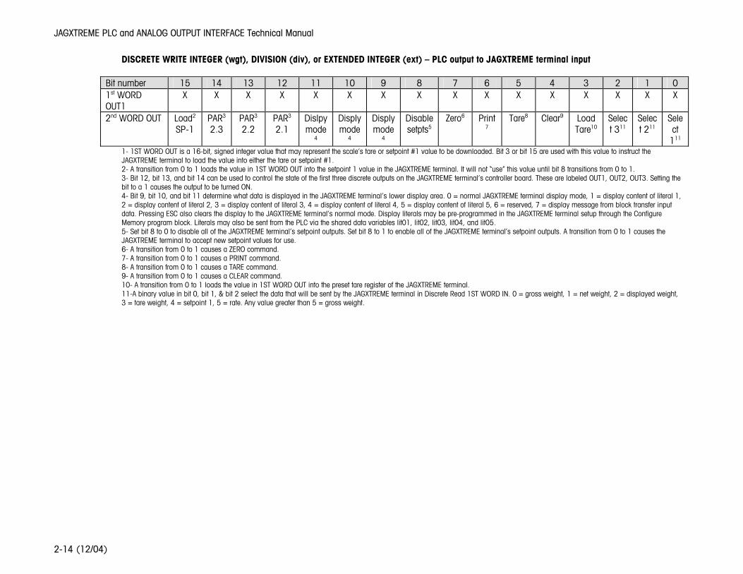
JAGXTREME PLC and ANALOG OUTPUT INTERFACE Technical Manual
2-14 (12/04)
DISCRETE WRITE INTEGER (wgt), DIVISION (div), or EXTENDED INTEGER (ext) – PLC output to JAGXTREME terminal input
Bit number 15 14 13 12 11 10 9 8 7 6 5 4 3 2 1 0 1st WORD OUT1
X X X X X X X X X X X X X X X X
2nd WORD OUT Load2 SP-1
PAR3 2.3
PAR3
2.2 PAR3
2.1 Dislpy mode
4
Disply mode
4
Disply mode
4
Disable setpts5
Zero6 Print7
Tare8 Clear9 Load Tare10
Select 311
Select 211
Select
111
1- 1ST WORD OUT is a 16-bit, signed integer value that may represent the scale’s tare or setpoint #1 value to be downloaded. Bit 3 or bit 15 are used with this value to instruct the JAGXTREME terminal to load the value into either the tare or setpoint #1. 2- A transition from 0 to 1 loads the value in 1ST WORD OUT into the setpoint 1 value in the JAGXTREME terminal. It will not “use” this value until bit 8 transitions from 0 to 1. 3- Bit 12, bit 13, and bit 14 can be used to control the state of the first three discrete outputs on the JAGXTREME terminal’s controller board. These are labeled OUT1, OUT2, OUT3. Setting the bit to a 1 causes the output to be turned ON. 4- Bit 9, bit 10, and bit 11 determine what data is displayed in the JAGXTREME terminal’s lower display area. 0 = normal JAGXTREME terminal display mode, 1 = display content of literal 1, 2 = display content of literal 2, 3 = display content of literal 3, 4 = display content of literal 4, 5 = display content of literal 5, 6 = reserved, 7 = display message from block transfer input data. Pressing ESC also clears the display to the JAGXTREME terminal’s normal mode. Display literals may be pre-programmed in the JAGXTREME terminal setup through the Configure Memory program block. Literals may also be sent from the PLC via the shared data variables lit01, lit02, lit03, lit04, and lit05. 5- Set bit 8 to 0 to disable all of the JAGXTREME terminal’s setpoint outputs. Set bit 8 to 1 to enable all of the JAGXTREME terminal’s setpoint outputs. A transition from 0 to 1 causes the JAGXTREME terminal to accept new setpoint values for use. 6- A transition from 0 to 1 causes a ZERO command. 7- A transition from 0 to 1 causes a PRINT command. 8- A transition from 0 to 1 causes a TARE command. 9- A transition from 0 to 1 causes a CLEAR command. 10- A transition from 0 to 1 loads the value in 1ST WORD OUT into the preset tare register of the JAGXTREME terminal. 11-A binary value in bit 0, bit 1, & bit 2 select the data that will be sent by the JAGXTREME terminal in Discrete Read 1ST WORD IN. 0 = gross weight, 1 = net weight, 2 = displayed weight, 3 = tare weight, 4 = setpoint 1, 5 = rate. Any value greater than 5 = gross weight.
Floating Point
Operational Overview
Chapter 2: PROFIBUS Data Definition
(12/04) 2-15
The following charts provide detailed information on the floating point data format. Read data refers to the PLC’s input data and write data refers to the PLC’s output data.
The PLC may control the rotation by sending alternate report next field commands (1 and 2). When the PLC changes to the next command, the terminal switches to the next value in the rotation. The terminal stores the rotation in its shared data so the rotation does not have to be re-initialized after each power cycle. When the PLC does not set up an input rotation, the default input rotation consists of gross weight only.
The terminal can also send a rotation of up to nine different real-time values for each scale. The PLC sends commands to the terminal to add a value to the rotation list. Once the rotation is established, the PLC must instruct the terminal to begins its rotation automatically or the PLC may control the pace of rotation by instructing the terminal advance to the next value. If the terminal is asked to automatically alternate its output data, it will switch to the next value in its rotation at the next A/D update. (The A/D update rate depends on the scale type. An analog scale has an update rate of 17 Hz or 58 milliseconds.)
The terminal can report two types of values to the PLC: real-time and static. When the PLC requests a real-time value, the terminal will acknowledge the command from the PLC once but will send and update the value at every A/D update. However, if the PLC requests a static value, the terminal will acknowledge the command from the PLC once and UPDATE the value once. The terminal will continue to send this “static” value until it receives a new command from the PLC. Gross weight, net weight, and rate are examples of real-time data. Tare weight, setpoint cutoff, dribble, and tolerance values are examples of static data.
The JAGXTREME terminal uses integer commands from the PLC to select the floating point weight output data. The terminal will recognize a command when it sees a new value in the scale’s command word. If the command has an associated floating point value (for example: loading a setpoint value), it must be loaded into the floating point value words before the command is issued. Once the terminal recognizes a command, it will acknowledge it by setting a new value in the command acknowledge bits of the scale’s command response word. It will also tell the PLC which floating point value is currently being sent (via the floating point input indicator bits of the command response word). The PLC will wait until it receives the command acknowledgment from the terminal before it sends another command.
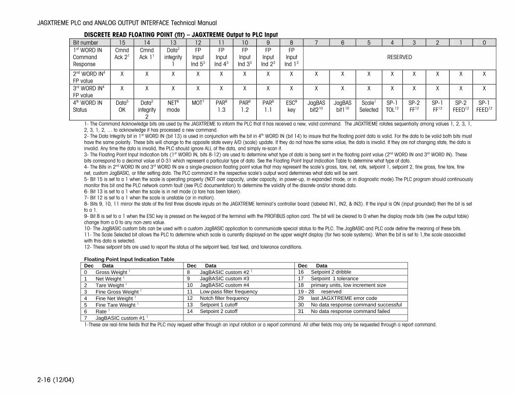
JAGXTREME PLC and ANALOG OUTPUT INTERFACE Technical Manual
DISCRETE READ FLOATING POINT (flt) – JAGXTREME Output to PLC Input Bit number 15 14 13 12 11 10 9 8 7 6 5 4 3 2 1 0 1st WORD IN Command Response
Cmnd Ack 21
Cmnd Ack 11
Data2 integrity
1
FP Input Ind 53
FP Input Ind 43
FP Input Ind 33
FP Input Ind 23
FP Input Ind 13
RESERVED
2nd WORD IN4
FP value X X X X X X X X X X X X X X X X
3rd WORD IN4
FP value X X X X X X X X X X X X X X X X
4th WORD IN Status
Data5 OK
Data2 integrity
2
NET6 mode
MOT7 PAR8 1.3
PAR8 1.2
PAR8 1.1
ESC9
key JagBAS bit210
JagBAS bit110
Scale1
Selected SP-1 TOL12
SP-2 FF12
SP-1 FF12
SP-2 FEED12
SP-1 FEED12
1- The Command Acknowledge bits are used by the JAGXTREME to inform the PLC that it has received a new, valid command. The JAGXTREME rotates sequentially among values 1, 2, 3, 1, 2, 3, 1, 2, … to acknowledge it has processed a new command. 2- The Data Integrity bit in 1st WORD IN (bit 13) is used in conjunction with the bit in 4th WORD IN (bit 14) to insure that the floating point data is valid. For the data to be valid both bits must have the same polarity. These bits will change to the opposite state every A/D (scale) update. If they do not have the same value, the data is invalid. If they are not changing state, the data is invalid. Any time the data is invalid, the PLC should ignore ALL of the data, and simply re-scan it. 3- The Floating Point Input Indication bits (1st WORD IN, bits 8-12) are used to determine what type of data is being sent in the floating point value (2nd WORD IN and 3rd WORD IN). These bits correspond to a decimal value of 0-31 which represent a particular type of data. See the Floating Point Input Indication Table to determine what type of data. 4- The Bits in 2nd WORD IN and 3rd WORD IN are a single-precision floating point value that may represent the scale’s gross, tare, net, rate, setpoint 1, setpoint 2, fine gross, fine tare, fine net, custom JagBASIC, or filter setting data. The PLC command in the respective scale’s output word determines what data will be sent. 5- Bit 15 is set to a 1 when the scale is operating properly (NOT over capacity, under capacity, in power-up, in expanded mode, or in diagnostic mode).The PLC program should continuously monitor this bit and the PLC network comm fault (see PLC documentation) to determine the validity of the discrete and/or shared data. 6- Bit 13 is set to a 1 when the scale is in net mode (a tare has been taken). 7- Bit 12 is set to a 1 when the scale is unstable (or in motion). 8- Bits 9, 10, 11 mirror the state of the first three discrete inputs on the JAGXTREME terminal’s controller board (labeled IN1, IN2, & IN3). If the input is ON (input grounded) then the bit is set to a 1. 9- Bit 8 is set to a 1 when the ESC key is pressed on the keypad of the terminal with the PROFIBUS option card. The bit will be cleared to 0 when the display mode bits (see the output table) change from a 0 to any non-zero value. 10- The JagBASIC custom bits can be used with a custom JagBASIC application to communicate special status to the PLC. The JagBASIC and PLC code define the meaning of these bits. 11- The Scale Selected bit allows the PLC to determine which scale is currently displayed on the upper weight display (for two scale systems). When the bit is set to 1,the scale associated with this data is selected. 12- These setpoint bits are used to report the status of the setpoint feed, fast feed, and tolerance conditions. Floating Point Input Indication Table Dec Data Dec Data Dec Data 0 Gross Weight 1 8 JagBASIC custom #2 1 16 Setpoint 2 dribble 1 Net Weight 1 9 JagBASIC custom #3 17 Setpoint 1 tolerance 2 Tare Weight 1 10 JagBASIC custom #4 18 primary units, low increment size 3 Fine Gross Weight 1 11 Low-pass filter frequency 19 - 28 reserved 4 Fine Net Weight 1 12 Notch filter frequency 29 last JAGXTREME error code 5 Fine Tare Weight 1 13 Setpoint 1 cutoff 30 No data response command successful 6 Rate 1 14 Setpoint 2 cutoff 31 No data response command failed 7 JagBASIC custom #1 1 1-These are real-time fields that the PLC may request either through an input rotation or a report command. All other fields may only be requested through a report command.
(12/04) 2-16
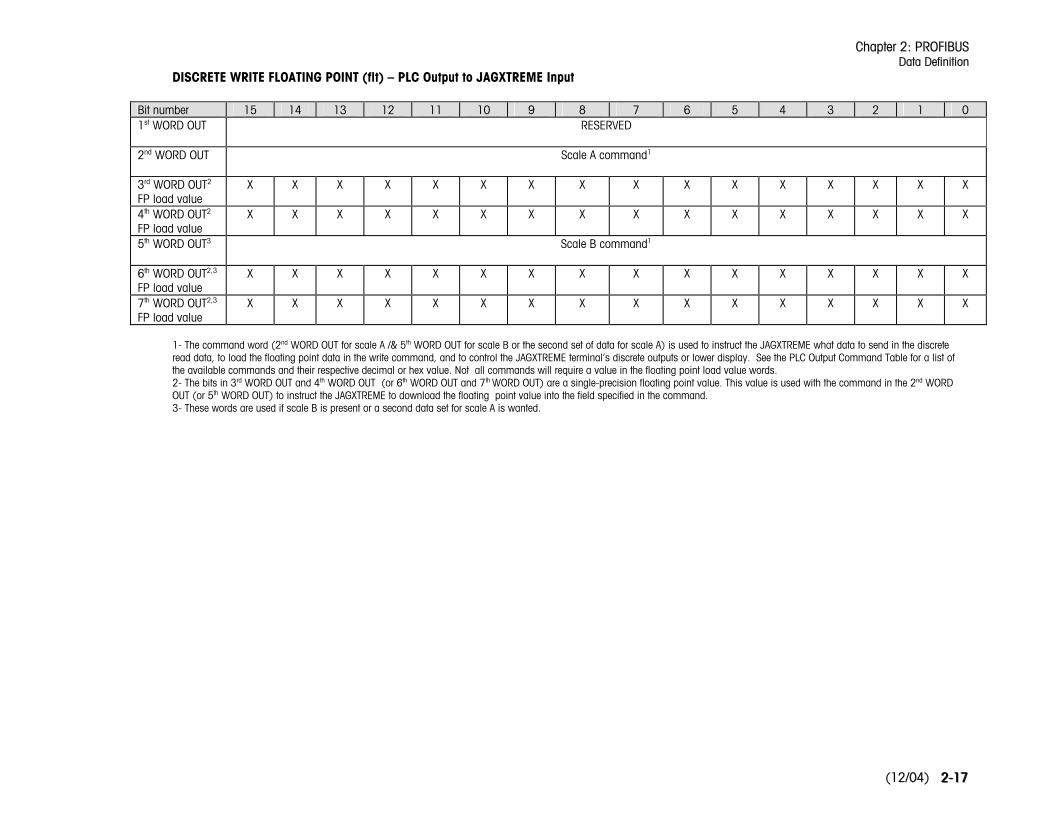
Chapter 2: PROFIBUS Data Definition
DISCRETE WRITE FLOATING POINT (flt) – PLC Output to JAGXTREME Input
Bit number 15 14 13 12 11 10 9 8 7 6 5 4 3 2 1 0 1st WORD OUT RESERVED
2nd WORD OUT
Scale A command1
3rd WORD OUT2
FP load value X X X X X X X X X X X X X X X X
4th WORD OUT2
FP load value X X X X X X X X X X X X X X X X
5th WORD OUT3 Scale B command1
6th WORD OUT2,3
FP load value X X X X X X X X X X X X X X X X
7th WORD OUT2,3 FP load value
X X X X X X X X X X X X X X X X
1- The command word (2nd WORD OUT for scale A /& 5th WORD OUT for scale B or the second set of data for scale A) is used to instruct the JAGXTREME what data to send in the discrete read data, to load the floating point data in the write command, and to control the JAGXTREME terminal’s discrete outputs or lower display. See the PLC Output Command Table for a list of the available commands and their respective decimal or hex value. Not all commands will require a value in the floating point load value words. 2- The bits in 3rd WORD OUT and 4th WORD OUT (or 6th WORD OUT and 7th WORD OUT) are a single-precision floating point value. This value is used with the command in the 2nd WORD OUT (or 5th WORD OUT) to instruct the JAGXTREME to download the floating point value into the field specified in the command. 3- These words are used if scale B is present or a second data set for scale A is wanted.
(12/04) 2-17 2-17
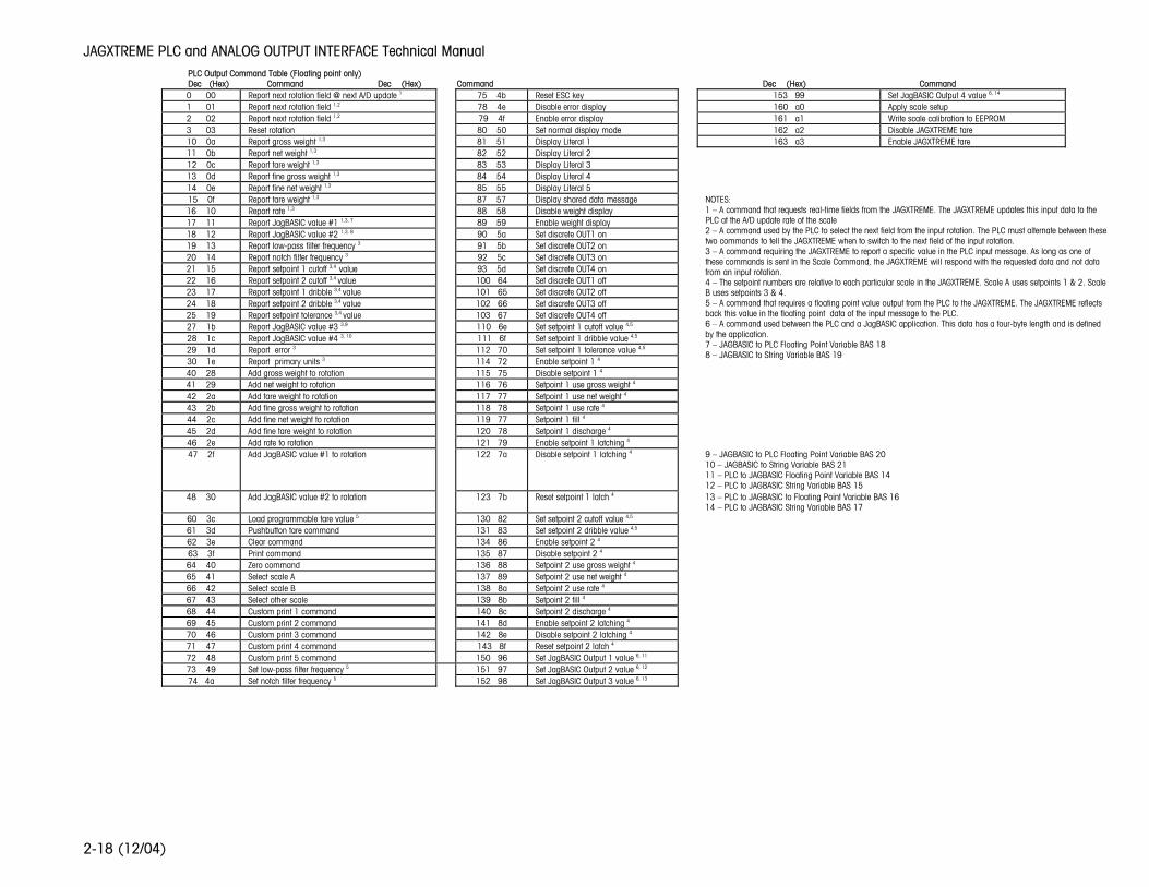
JAGXTREME PLC and ANALOG OUTPUT INTERFACE Technical Manual
(12/04) 2-18
PLC Output Command Table (Floating point only) Dec (Hex) Command Dec (Hex) Command Dec (Hex) Command 0 00 Report next rotation field @ next A/D update 1 75 4b Reset ESC key 153 99 Set JagBASIC Output 4 value 6, 14
1 01 Report next rotation field 1,2 78 4e Disable error display 160 a0 Apply scale setup 2 02 Report next rotation field 1,2 79 4f Enable error display 161 a1 Write scale calibration to EEPROM 3 03 Reset rotation 80 50 Set normal display mode 162 a2 Disable JAGXTREME tare 10 0a Report gross weight 1,3 81 51 Display Literal 1 163 a3 Enable JAGXTREME tare 11 0b Report net weight 1,3 82 52 Display Literal 2 12 0c Report tare weight 1,3 83 53 Display Literal 3 13 0d Report fine gross weight 1,3 84 54 Display Literal 4 14 0e Report fine net weight 1,3 85 55 Display Literal 5 15 0f Report tare weight 1,3 87 57 Display shared data message 16 10 Report rate 1,3 88 58 Disable weight display 17 11 Report JagBASIC value #1 1,3, 7 89 59 Enable weight display 18 12 Report JagBASIC value #2 1,3, 8 90 5a Set discrete OUT1 on 19 13 Report low-pass filter frequency 3 91 5b Set discrete OUT2 on 20 14 Report notch filter frequency 3 92 5c Set discrete OUT3 on 21 15 Report setpoint 1 cutoff 3,4 value 93 5d Set discrete OUT4 on 22 16 Report setpoint 2 cutoff 3,4 value 100 64 Set discrete OUT1 off 23 17 Report setpoint 1 dribble 3,4 value 101 65 Set discrete OUT2 off 24 18 Report setpoint 2 dribble 3,4 value 102 66 Set discrete OUT3 off 25 19 Report setpoint tolerance 3,4 value 103 67 Set discrete OUT4 off 27 1b Report JagBASIC value #3 3,9 110 6e Set setpoint 1 cutoff value 4,5 28 1c Report JagBASIC value #4 3, 10 111 6f Set setpoint 1 dribble value 4,5 29 1d Report error 3 112 70 Set setpoint 1 tolerance value 4,5 30 1e Report primary units 3 114 72 Enable setpoint 1 4 40 28 Add gross weight to rotation 115 75 Disable setpoint 1 4 41 29 Add net weight to rotation 116 76 Setpoint 1 use gross weight 4 42 2a Add tare weight to rotation 117 77 Setpoint 1 use net weight 4 43 2b Add fine gross weight to rotation 118 78 Setpoint 1 use rate 4 44 2c Add fine net weight to rotation 119 77 Setpoint 1 fill 4 45 2d Add fine tare weight to rotation 120 78 Setpoint 1 discharge 4 46 2e Add rate to rotation 121 79 Enable setpoint 1 latching 4
NOTES: 1 – A command that requests real-time fields from the JAGXTREME. The JAGXTREME updates this input data to the PLC at the A/D update rate of the scale 2 – A command used by the PLC to select the next field from the input rotation. The PLC must alternate between these two commands to tell the JAGXTREME when to switch to the next field of the input rotation. 3 – A command requiring the JAGXTREME to report a specific value in the PLC input message. As long as one of these commands is sent in the Scale Command, the JAGXTREME will respond with the requested data and not data from an input rotation. 4 – The setpoint numbers are relative to each particular scale in the JAGXTREME. Scale A uses setpoints 1 & 2. Scale B uses setpoints 3 & 4. 5 – A command that requires a floating point value output from the PLC to the JAGXTREME. The JAGXTREME reflects back this value in the floating point data of the input message to the PLC. 6 – A command used between the PLC and a JagBASIC application. This data has a four-byte length and is defined by the application. 7 – JAGBASIC to PLC Floating Point Variable BAS 18 8 – JAGBASIC to String Variable BAS 19
47 2f Add JagBASIC value #1 to rotation 122 7a Disable setpoint 1 latching 4 9 – JAGBASIC to PLC Floating Point Variable BAS 20 10 – JAGBASIC to String Variable BAS 21 11 – PLC to JAGBASIC Floating Point Variable BAS 14 12 – PLC to JAGBASIC String Variable BAS 15
48 30 Add JagBASIC value #2 to rotation 123 7b Reset setpoint 1 latch 4 13 – PLC to JAGBASIC to Floating Point Variable BAS 16 14 – PLC to JAGBASIC String Variable BAS 17
60 3c Load programmable tare value 5 130 82 Set setpoint 2 cutoff value 4,5 61 3d Pushbutton tare command 131 83 Set setpoint 2 dribble value 4,5 62 3e Clear command 134 86 Enable setpoint 2 4 63 3f Print command 135 87 Disable setpoint 2 4 64 40 Zero command 136 88 Setpoint 2 use gross weight 4 65 41 Select scale A 137 89 Setpoint 2 use net weight 4 66 42 Select scale B 138 8a Setpoint 2 use rate 4 67 43 Select other scale 139 8b Setpoint 2 fill 4 68 44 Custom print 1 command 140 8c Setpoint 2 discharge 4 69 45 Custom print 2 command 141 8d Enable setpoint 2 latching 4 70 46 Custom print 3 command 142 8e Disable setpoint 2 latching 4 71 47 Custom print 4 command 143 8f Reset setpoint 2 latch 4 72 48 Custom print 5 command 150 96 Set JagBASIC Output 1 value 6, 11 73 49 Set low-pass filter frequency 5 151 97 Set JagBASIC Output 2 value 6, 12 74 4a Set notch filter frequency 5 152 98 Set JagBASIC Output 3 value 6, 13
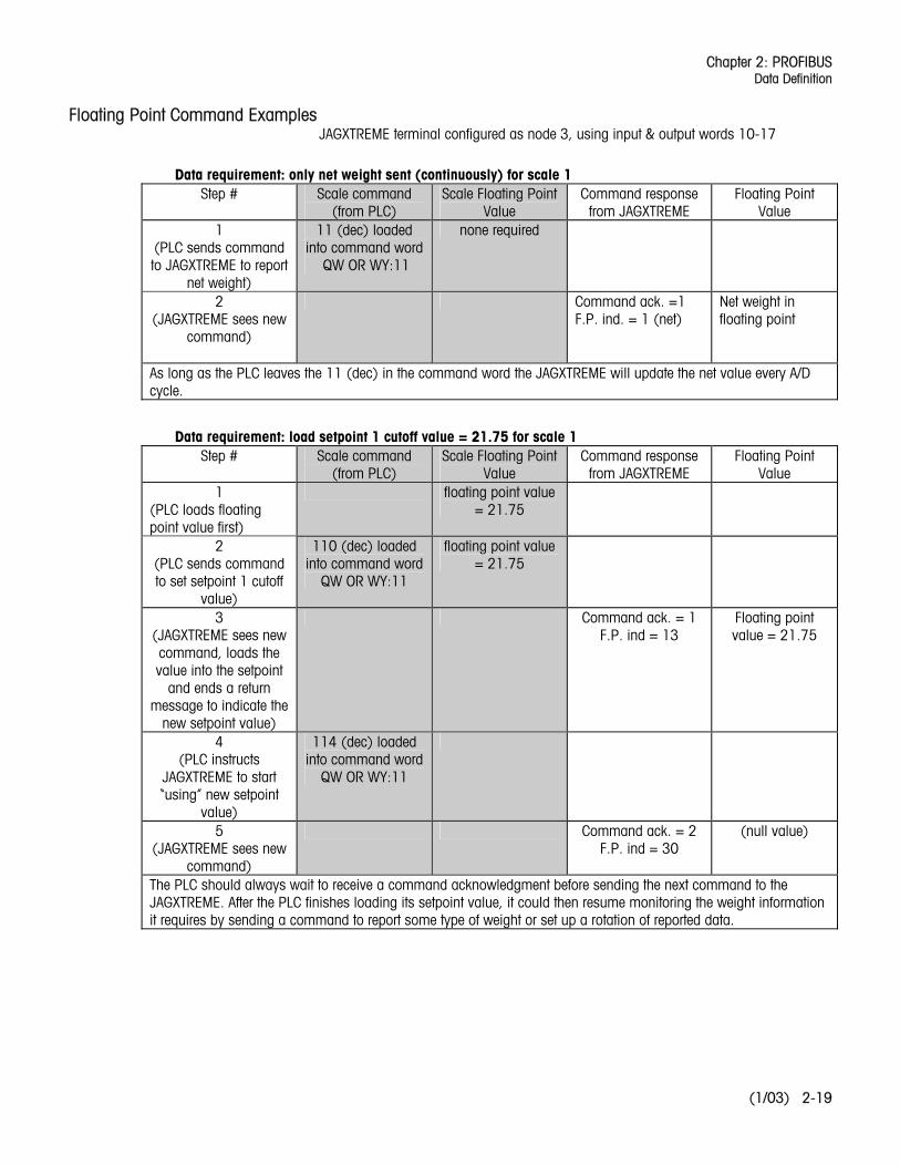
Chapter 2: PROFIBUS Data Definition
Floating Point Command Examples
JAGXTREME terminal configured as node 3, using input & output words 10-17
Data requirement: only net weight sent (continuously) for scale 1
Step # Scale command (from PLC)
Scale Floating Point Value
Command response from JAGXTREME
Floating Point Value
1 (PLC sends command to JAGXTREME to report
net weight)
11 (dec) loaded into command word
QW OR WY:11
none required
2 (JAGXTREME sees new
command)
Command ack. =1 F.P. ind. = 1 (net)
Net weight in floating point
As long as the PLC leaves the 11 (dec) in the command word the JAGXTREME will update the net value every A/D cycle.
Data requirement: load setpoint 1 cutoff value = 21.75 for scale 1
Step # Scale command (from PLC)
Scale Floating Point Value
Command response from JAGXTREME
Floating Point Value
1 (PLC loads floating point value first)
floating point value = 21.75
2 (PLC sends command to set setpoint 1 cutoff
value)
110 (dec) loaded into command word
QW OR WY:11
floating point value = 21.75
3 (JAGXTREME sees new command, loads the value into the setpoint
and ends a return message to indicate the
new setpoint value)
Command ack. = 1 F.P. ind = 13
Floating point value = 21.75
4 (PLC instructs
JAGXTREME to start “using” new setpoint
value)
114 (dec) loaded into command word
QW OR WY:11
5 (JAGXTREME sees new
command)
Command ack. = 2 F.P. ind = 30
(null value)
The PLC should always wait to receive a command acknowledgment before sending the next command to the JAGXTREME. After the PLC finishes loading its setpoint value, it could then resume monitoring the weight information it requires by sending a command to report some type of weight or set up a rotation of reported data.
(1/03)
2-19
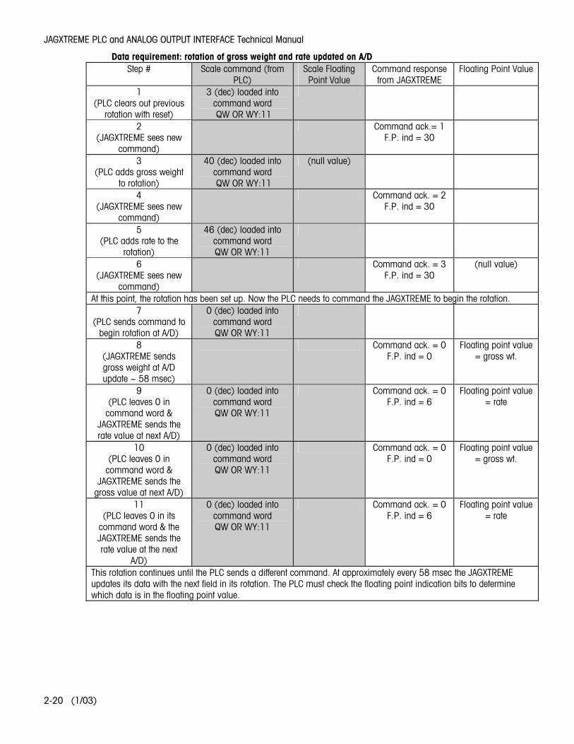
JAGXTREME PLC and ANALOG OUTPUT INTERFACE Technical Manual
Data requirement: rotation of gross weight and rate updated on A/D Step # Scale command (from
PLC) Scale Floating Point Value
Command response from JAGXTREME
Floating Point Value
1 (PLC clears out previous
rotation with reset)
3 (dec) loaded into command word QW OR WY:11
2 (JAGXTREME sees new
command)
Command ack.= 1 F.P. ind = 30
3 (PLC adds gross weight
to rotation)
40 (dec) loaded into command word QW OR WY:11
(null value)
4 (JAGXTREME sees new
command)
Command ack. = 2 F.P. ind = 30
5 (PLC adds rate to the
rotation)
46 (dec) loaded into command word QW OR WY:11
6 (JAGXTREME sees new
command)
Command ack. = 3 F.P. ind = 30
(null value)
At this point, the rotation has been set up. Now the PLC needs to command the JAGXTREME to begin the rotation. 7
(PLC sends command to begin rotation at A/D)
0 (dec) loaded into command word QW OR WY:11
8 (JAGXTREME sends gross weight at A/D update ~ 58 msec)
Command ack. = 0 F.P. ind = 0
Floating point value = gross wt.
9 (PLC leaves 0 in
command word & JAGXTREME sends the rate value at next A/D)
0 (dec) loaded into command word QW OR WY:11
Command ack. = 0 F.P. ind = 6
Floating point value = rate
10 (PLC leaves 0 in
command word & JAGXTREME sends the
gross value at next A/D)
0 (dec) loaded into command word QW OR WY:11
Command ack. = 0 F.P. ind = 0
Floating point value = gross wt.
11 (PLC leaves 0 in its
command word & the JAGXTREME sends the rate value at the next
A/D)
0 (dec) loaded into command word QW OR WY:11
Command ack. = 0 F.P. ind = 6
Floating point value = rate
This rotation continues until the PLC sends a different command. At approximately every 58 msec the JAGXTREME updates its data with the next field in its rotation. The PLC must check the floating point indication bits to determine which data is in the floating point value.
(1/03) 2-20
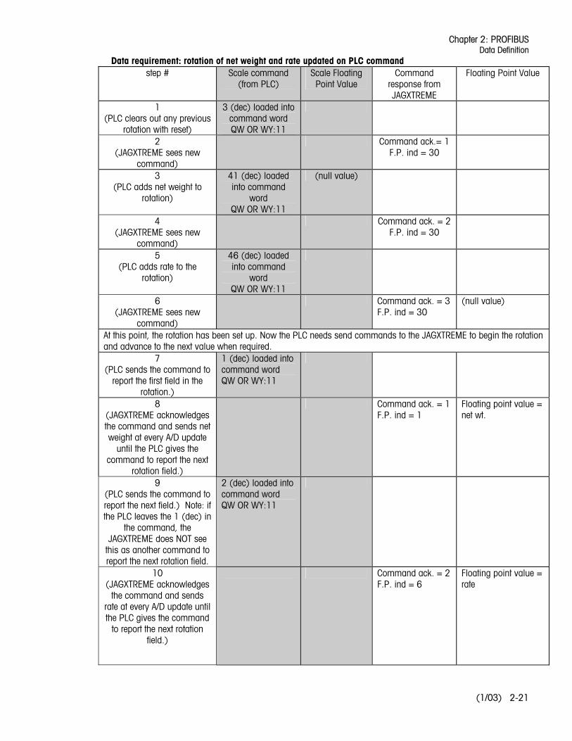
Chapter 2: PROFIBUS Data Definition
Data requirement: rotation of net weight and rate updated on PLC command step # Scale command
(from PLC) Scale Floating Point Value
Command response from JAGXTREME
Floating Point Value
1 (PLC clears out any previous
rotation with reset)
3 (dec) loaded into command word QW OR WY:11
2 (JAGXTREME sees new
command)
Command ack.= 1 F.P. ind = 30
3 (PLC adds net weight to
rotation)
41 (dec) loaded into command
word QW OR WY:11
(null value)
4 (JAGXTREME sees new
command)
Command ack. = 2 F.P. ind = 30
5 (PLC adds rate to the
rotation)
46 (dec) loaded into command
word QW OR WY:11
6 (JAGXTREME sees new
command)
Command ack. = 3 F.P. ind = 30
(null value)
At this point, the rotation has been set up. Now the PLC needs send commands to the JAGXTREME to begin the rotation and advance to the next value when required.
7 (PLC sends the command to
report the first field in the rotation.)
1 (dec) loaded into command word QW OR WY:11
8 (JAGXTREME acknowledges the command and sends net weight at every A/D update
until the PLC gives the command to report the next
rotation field.)
Command ack. = 1 F.P. ind = 1
Floating point value = net wt.
9 (PLC sends the command to report the next field.) Note: if the PLC leaves the 1 (dec) in
the command, the JAGXTREME does NOT see
this as another command to report the next rotation field.
2 (dec) loaded into command word QW OR WY:11
10 (JAGXTREME acknowledges
the command and sends rate at every A/D update until the PLC gives the command
to report the next rotation field.)
Command ack. = 2 F.P. ind = 6
Floating point value = rate
(1/03)
2-21
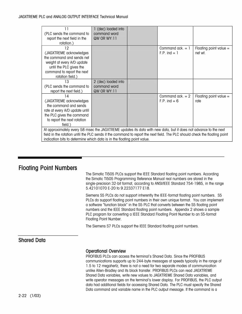
JAGXTREME PLC and ANALOG OUTPUT INTERFACE Technical Manual
11
(PLC sends the command to report the next field in the
rotation.)
1 (dec) loaded into command word QW OR WY:11
12 (JAGXTREME acknowledges the command and sends net weight at every A/D update
until the PLC gives the command to report the next
rotation field.)
Command ack. = 1 F.P. ind = 1
Floating point value = net wt.
13 (PLC sends the command to
report the next field.)
2 (dec) loaded into command word QW OR WY:11
14 (JAGXTREME acknowledges
the command and sends rate at every A/D update until the PLC gives the command
to report the next rotation field.)
Command ack. = 2 F.P. ind = 6
Floating point value = rate
At approximately every 58 msec the JAGXTREME updates its data with new data, but it does not advance to the next field in the rotation until the PLC sends it the command to report the next field. The PLC should check the floating point indication bits to determine which data is in the floating point value.
Floating Point Numbers The Simatic TI505 PLCs support the IEEE Standard floating point numbers. According the Simatic TI505 Programming Reference Manual real numbers are stored in the single-precision 32-bit format, according to ANSI/IEEE Standard 754-1985, in the range 5.42101070 E-20 to 9.22337177 E18.
Siemens S5 PLCs do not support inherently the IEEE-format floating point numbers. S5 PLCs do support floating point numbers in their own unique format. You can implement a software “function block” in the S5 PLC that converts between the S5 floating point numbers and the IEEE Standard floating point numbers. Appendix 2 shows a sample PLC program for converting a IEEE Standard Floating Point Number to an S5-format Floating Point Number.
The Siemens S7 PLCs support the IEEE Standard floating point numbers.
Shared Data
Operational Overview PROFIBUS PLCs can access the terminal’s Shared Data. Since the PROFIBUS communications supports up to 244-byte messages at speeds typically in the range of 1.5 to 12 megahertz, there is not a need for two separate modes of communication unlike Allen-Bradley and its block transfer. PROFIBUS PLCs can read JAGXTREME Shared Data variables, write new values to JAGXTREME Shared Data variables, and write operator messages on the terminal’s lower display. For PROFIBUS, the PLC output data had additional fields for accessing Shared Data. The PLC must specify the Shared Data command and variable name in the PLC output message. If the command is a
(1/03) 2-22
Chapter 2: PROFIBUS Floating Point Numbers
write command, then the PLC output message must also contain the write field value. The maximum length of the value is 20 bytes. When the Shared Data command is a read command, the PLC input message will have a read field containing the data from the Shared Data variable specified in the output message. The maximum length of the data reported in the read field is 20 bytes. The Shared Data variables are self-typing. The JAGXTREME terminal determines the type of any valid data field in the message from the variable’s name and definition in Shared Data. The terminal will not allow string data to be written in a floating point variable or visa versa.
Shared Data Input The input information for the shared data consists of two sections: the shared data status and the shared data read field value (if requested by the shared data output command). The shared data status information is a word that contains an integer value. This integer value represents one of the following status values:
0 Null status 1 Command completed successfully 2 Invalid shared data name 3 Invalid shared data command 4 Cannot write because field is write-protected (legal for trade) 5 Cannot access remote JAGXTREME
Please refer to the Shared Data Reference Guide for a complete listing of Shared Data Fields.
The shared data read field value contains the value of the shared data variable specified in the shared data output (from the PLC to the terminal). It is only present when the command from the shared data output requests read shared data. This value is self-typing; for example, it could be a floating point number or a string variable. The length is determined by the variable selected but will not exceed 20 bytes. See the tables following the Shared Data Output for a list of possible variables and their contents.
Shared Data Output The output information for the shared data consists of four sections: the shared data command, the shared data name, the shared data variable name, and the shared data write value (if required by the shared data output command). The shared data command information is a word that contains an integer value. This integer value represents one of the following status values:
0 Null command 1 Read shared data 2 Write shared data 3 Write to JAGXTREME lower display
The terminal processes a shared data command “on demand” by the PLC. When a new value is placed in the shared data command word, the terminal will perform the command issued. The terminal does not provide “real time” information to the PLC; it supplies a “snapshot’ of the data not an automatic update of new values of the same shared data command. Instead, the PLC must request the information again by setting a new value in the shared data command word.
To do successive reads, for example, the PLC must alternate between a “null” command and a “read” command in the shared data command word. For the most efficient processing, the PLC should set up the terminal name, the variable name, and the write value (if any) while it is setting the “null” command. Once that is completed, the PLC can then set the shared data command to “read” or “write”.
(1/03)
2-23
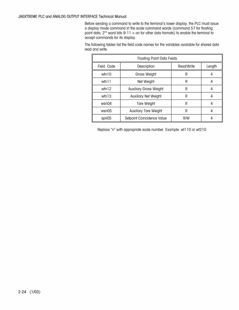
JAGXTREME PLC and ANALOG OUTPUT INTERFACE Technical Manual
Before sending a command to write to the terminal’s lower display, the PLC must issue a display mode command in the scale command words (command 57 for floating point data; 2nd word bits 9-11 = on for other data formats) to enable the terminal to accept commands for its display.
The following tables list the field code names for the variables available for shared data read and write.
Floating Point Data Fields
Field Code Description Read/Write Length
wtn10 Gross Weight R 4
wtn11 Net Weight R 4
wtn12 Auxiliary Gross Weight R 4
wtn13 Auxiliary Net Weight R 4
wsn04 Tare Weight R 4
wsn05 Auxiliary Tare Weight R 4
spn05 Setpoint Coincidence Value R/W 4
Replace “n” with appropriate scale number. Example: wt110 or wt210.
(1/03) 2-24
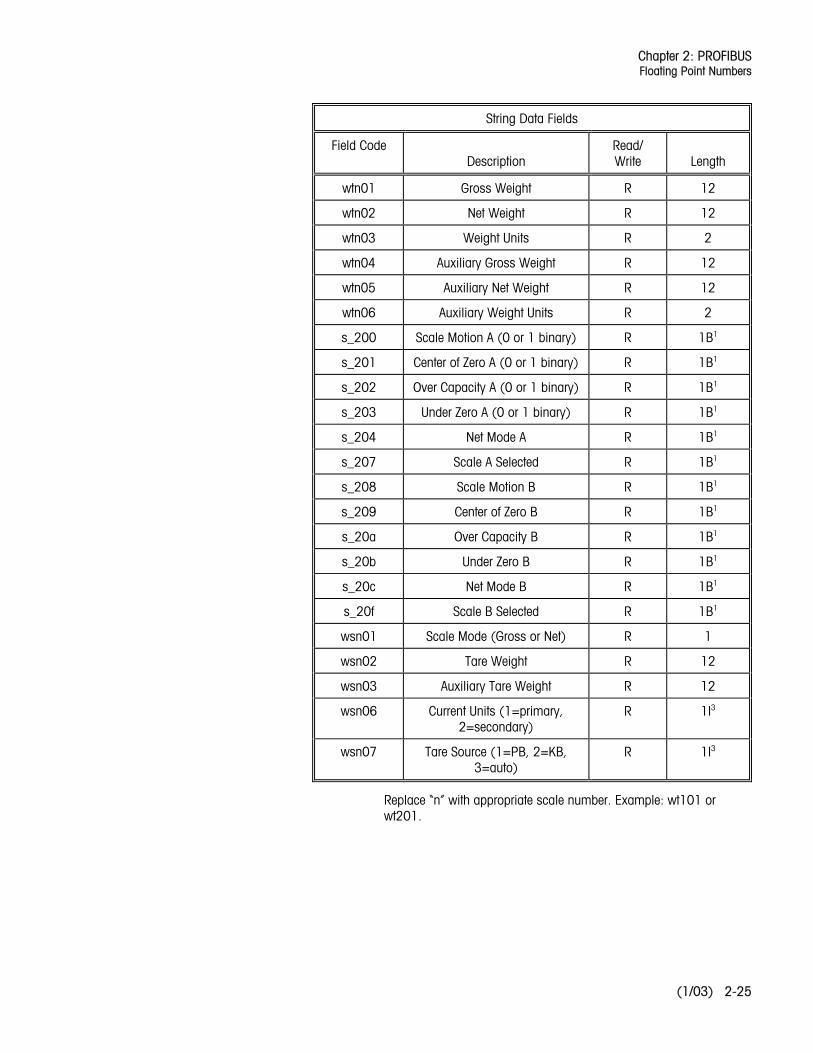
Chapter 2: PROFIBUS Floating Point Numbers
String Data Fields
Field Code Description
Read/ Write
Length
wtn01 Gross Weight R 12
wtn02 Net Weight R 12
wtn03 Weight Units R 2
wtn04 Auxiliary Gross Weight R 12
wtn05 Auxiliary Net Weight R 12
wtn06 Auxiliary Weight Units R 2
s_200 Scale Motion A (0 or 1 binary) R 1B1
s_201 Center of Zero A (0 or 1 binary) R 1B1
s_202 Over Capacity A (0 or 1 binary) R 1B1
s_203 Under Zero A (0 or 1 binary) R 1B1
s_204 Net Mode A R 1B1
s_207 Scale A Selected R 1B1
s_208 Scale Motion B R 1B1
s_209 Center of Zero B R 1B1
s_20a Over Capacity B R 1B1
s_20b Under Zero B R 1B1
s_20c Net Mode B R 1B1
s_20f Scale B Selected R 1B1
wsn01 Scale Mode (Gross or Net) R 1
wsn02 Tare Weight R 12
wsn03 Auxiliary Tare Weight R 12
wsn06 Current Units (1=primary, 2=secondary)
R 1I3
wsn07 Tare Source (1=PB, 2=KB, 3=auto)
R 1I3
Replace “n” with appropriate scale number. Example: wt101 or wt201.
(1/03)
2-25
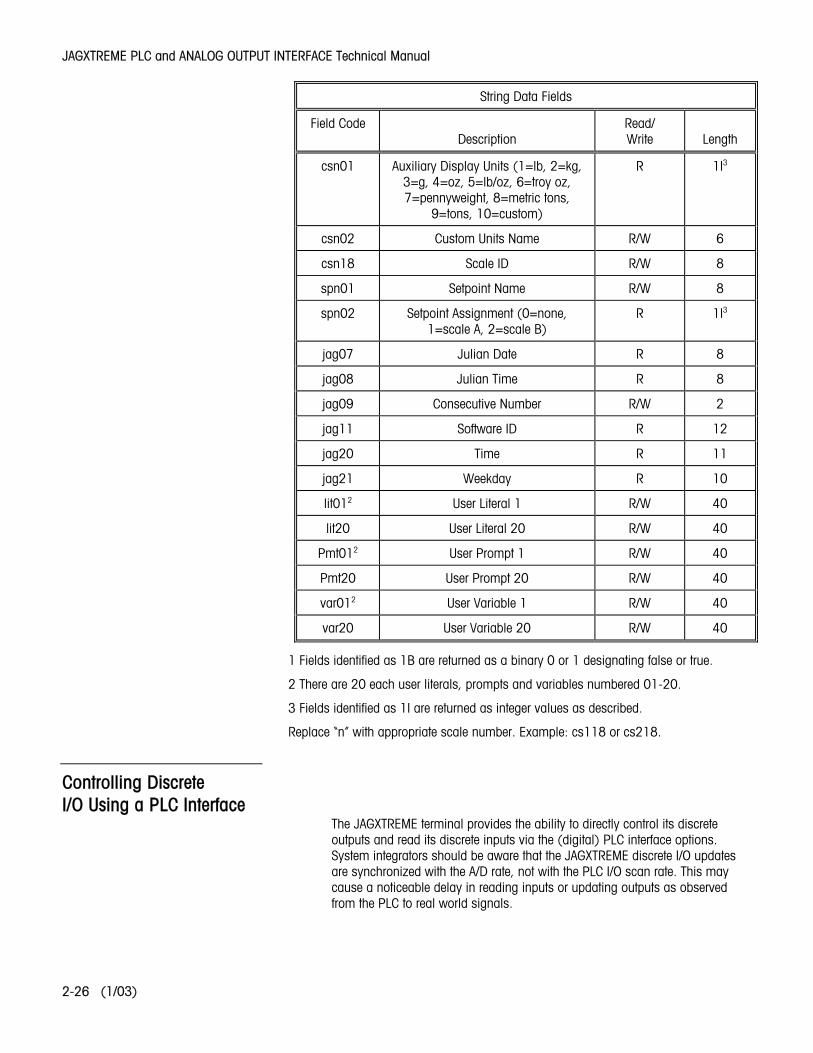
JAGXTREME PLC and ANALOG OUTPUT INTERFACE Technical Manual
String Data Fields
Field Code Description
Read/ Write
Length
csn01 Auxiliary Display Units (1=lb, 2=kg, 3=g, 4=oz, 5=lb/oz, 6=troy oz, 7=pennyweight, 8=metric tons,
9=tons, 10=custom)
R 1I3
csn02 Custom Units Name R/W 6
csn18 Scale ID R/W 8
spn01 Setpoint Name R/W 8
spn02 Setpoint Assignment (0=none, 1=scale A, 2=scale B)
R 1I3
jag07 Julian Date R 8
jag08 Julian Time R 8
jag09 Consecutive Number R/W 2
jag11 Software ID R 12
jag20 Time R 11
jag21 Weekday R 10
lit012 User Literal 1 R/W 40
lit20 User Literal 20 R/W 40
Pmt012 User Prompt 1 R/W 40
Pmt20 User Prompt 20 R/W 40
var012 User Variable 1 R/W 40
var20 User Variable 20 R/W 40
1 Fields identified as 1B are returned as a binary 0 or 1 designating false or true.
2 There are 20 each user literals, prompts and variables numbered 01-20.
3 Fields identified as 1I are returned as integer values as described.
Replace “n” with appropriate scale number. Example: cs118 or cs218.
Controlling Discrete I/O Using a PLC Interface
The JAGXTREME terminal provides the ability to directly control its discrete outputs and read its discrete inputs via the (digital) PLC interface options. System integrators should be aware that the JAGXTREME discrete I/O updates are synchronized with the A/D rate, not with the PLC I/O scan rate. This may cause a noticeable delay in reading inputs or updating outputs as observed from the PLC to real world signals.
(1/03) 2-26
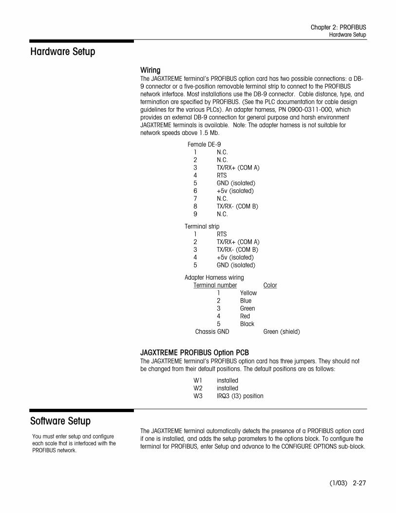
Chapter 2: PROFIBUS Hardware Setup
Hardware Setup
Wiring The JAGXTREME terminal’s PROFIBUS option card has two possible connections: a DB-9 connector or a five-position removable terminal strip to connect to the PROFIBUS network interface. Most installations use the DB-9 connector. Cable distance, type, and termination are specified by PROFIBUS. (See the PLC documentation for cable design guidelines for the various PLCs). An adapter harness, PN 0900-0311-000, which provides an external DB-9 connection for general purpose and harsh environment JAGXTREME terminals is available. Note: The adapter harness is not suitable for network speeds above 1.5 Mb.
Female DE-9 1 N.C. 2 N.C. 3 TX/RX+ (COM A) 4 RTS 5 GND (isolated) 6 +5v (isolated) 7 N.C. 8 TX/RX- (COM B) 9 N.C.
Terminal strip 1 RTS 2 TX/RX+ (COM A) 3 TX/RX- (COM B) 4 +5v (isolated) 5 GND (isolated)
Adapter Harness wiring Terminal number Color
1 Yellow 2 Blue 3 Green 4 Red 5 Black
Chassis GND Green (shield)
JAGXTREME PROFIBUS Option PCB The JAGXTREME terminal’s PROFIBUS option card has three jumpers. They should not be changed from their default positions. The default positions are as follows:
W1 installed W2 installed W3 IRQ3 (I3) position
Software Setup The JAGXTREME terminal automatically detects the presence of a PROFIBUS option card if one is installed, and adds the setup parameters to the options block. To configure the terminal for PROFIBUS, enter Setup and advance to the CONFIGURE OPTIONS sub-block.
You must enter setup and configure each scale that is interfaced with the PROFIBUS network.
(1/03)
2-27
JAGXTREME PLC and ANALOG OUTPUT INTERFACE Technical Manual
Scale Setup Sub-Block The Scale Setup block lets you specify how the PROFIBUS interface is used. Several options are available to correspond with your system setup. Reset to Factory returns all
parameters for this block to their original settings. You cannot reset a single value or specify only a few of the sub-block values.
To configure the block:
Press ENTER at the PROFIBUS prompt to access the program block.
Press ENTER at the Scale Setup prompt. At the Data Format? prompt, press SELECT to choose the desired weight display option:
Local refers to a scale in the same terminal as the PROFIBUS option. Remote refers to a scale interfaced across Ethernet.
Wgt—displays scale weight in the selected weight unit (lb, kg, or g).
Div—displays scale weight in display divisions. The PLC multiplies the display divisions by the increment size to calculate the weight in display units.
Ext—displays scale weight in the extended 21 signed bit format.
Flt---displays weight in floating point data format
The divisions display option is useful for heavy capacity scales that exceed the ± 32767 range of a signed integer in displayed weight units.
Please refer to the Discrete Read and Discrete Write tables in this manual for additional information on mapping of discrete read data to the PLC.
• At the Nbr of Scales? prompt, press SELECT to display the number of scales to be interfaced (1, 2, 3, or 4).
• At the Scale N? prompt, press SELECT to indicate if the designated scale is local or remote.
• For remote scales, select the terminal number at the Node? prompt.
• At the Internal Scale? prompt, identify each scale as A, B, C or D.
• Press ENTER to continue to the next sub-block. Press ESC to exit setup mode.
Node Communications Sub-block
This sub-block lets you enter the PROFIBUS network communication parameters. The JAGXTREME terminal programs the Node Adapter Chip with these parameters. This manual does not attempt to give
all information and configuration parameters for a PROFIBUS network. Please refer to the PLC documentation for more information on specific network performance.
• Press ENTER at the Node Communicate prompt to configure communications parameters.
• At the Rack Address? prompt, use the numeric keys to input the node address (0-126), then press ENTER.
Reset to Factory Sub-block You can reset all of the parameters for this program block to the original default values.
To reset the program block parameters:
• Press ENTER at the Reset to Factory prompt.
• At the Are You Sure? prompt, press SELECT to highlight Y(es) to confirm and reset the values to factory defaults, or select N(o) if you do not wish to reset the values.
• Press ESCAPE to exit the sub-block.
• Press SELECT to continue to another program block if desired.
(1/03) 2-28
Chapter 2: PROFIBUS Troubleshooting
PROFIBUS GSD or Type Files
There are eight configurations of the PROFIBUS GSD or type file for the JAGXTREME terminal’s different combinations of data formats. The length of the messages is different for each of the data formats, but the length of the input and output messages are the same within each format. The JAGXTREME supports the following message types:
Length Functionality
4 bytes (2 words in/ 2 words out) One scale in int, div, or ext
8 bytes (4 words in/ 4 words out) Two scales in int, div, or ext
12 bytes (6 words in/ 6 words out) Three scales in int, div, or ext
16 bytes (8 words in/ 8 words out) Four scales in int, div, or ext; OR
One or two scales in flt
24 bytes (12 words in/ 12 words out) Three scales in flt
32 bytes (16 words in/ 16 words out) Four scales in flt
56 bytes (28 words in/ 28 words out) Four scales in flt, int, div, or ext with
The PROFIBUS GSD files for the JAGXTREME are available free of charge. They can be ordered from METTLER TOLEDO in a kit, PN 0917-0250, which also includes a .200 file for ET200 applications. The GSD file can also be downloaded free of charge from the PROFIBUS website: www.profibus.com.
Troubleshooting
JAGXTREME Terminal’s PROFIBUS Option PCB Status Lights
The PROFIBUS option PCB has two status LEDs that indicate network port activity.
(1/03)
2-29
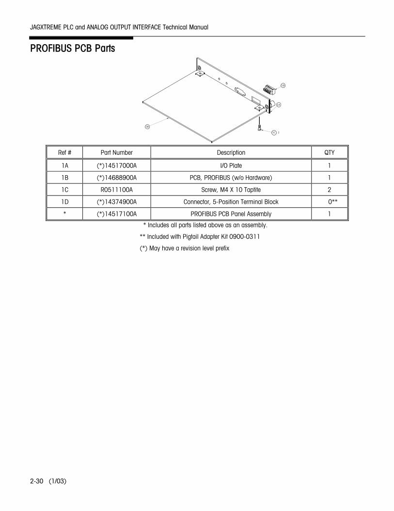
JAGXTREME PLC and ANALOG OUTPUT INTERFACE Technical Manual
PROFIBUS PCB Parts
PROFIBUS PCB Assembly
1A
1C 2
1B
1D
Ref # Part Number Description QTY
1A (*)14517000A I/O Plate 1
1B (*)14688900A PCB, PROFIBUS (w/o Hardware) 1
1C R0511100A Screw, M4 X 10 Taptite 2
1D (*)14374900A Connector, 5-Position Terminal Block 0**
* (*)14517100A PROFIBUS PCB Panel Assembly 1
* Includes all parts listed above as an assembly.
** Included with Pigtail Adapter Kit 0900-0311
(*) May have a revision level prefix
(1/03) 2-30
Chapter 2: PROFIBUS Siemens Simatic S5 Setup Example
Siemens Simatic S5 Setup Example
The IM 308-C Hardware Interface Card in the Siemens S5 PLC supports the PROFIBUS Interface. The IM 308-C is configured with a FLASH card that is programmed on a PC.
COM ET 200 Software The COM ET 200 Program runs under PC Windows 3.1 to build the IM 308-C configuration and write it to the FLASH card. An example setup is as follows.
Note: A copy of a self-extracting ZIP file named ME6713.EXE is available from the technical support BBS (614) 841-5169. This file is located in the JAGXTREME LIB and contains both Windows® and DOS® type files. It is also available from the PROFIBUS website: http://www.profibus.com
JAGXTREME Type File Example
Comment: JAGXTREME
Order No.: blank for now
Station Type: JAGXTREME
Manufacturer: METO
Family: JAGXTREME
Periphery: JAGXTREME
ASCI Type: SPC3
Manufacturer ID: 6713 (METO6713.GSD) This is in hex.
Min. Cycle: default
Programmable via bus: no
SYNC-able: No
FREEZE-able: No
Modular Station: No
Active Station: No
Even number of Slots: No
Baud Rates: Baud rates from 9.6K baud to 12 Mbaud, inclusively.
Slots
Max. number of inputs: 56 bytes
Max. number of outputs: 56 bytes
Max. address ID’s: 16
Number of diagnostics: 7 bytes
Number of parameter: 7 bytes
Predefined bytes: none
Predefined IDs: none
(1/03)
2-31
JAGXTREME PLC and ANALOG OUTPUT INTERFACE Technical Manual
Configuration File Sample
Bus Designation: PROFIBUS-DP
Bus Profile: PROFIBUS-DP
Baud: 12000 kBaud
Repeater on Bus: No
Parameters: Use Defaults
Host Designation: HOST System 1
Host Type: S5-115U/H / CPU942B
Reserve address areas for inputs
Start: P000
End: P027
Reserve address areas for outputs
Start: P000
End: P027
Power up delay: 20 seconds
Master Parameters
Station designation: Master System 1
Station type: IM 308-C
In host: Host System 1
Addressing: Linear
Number of IM 308-C: 0
Station number: 1
Multiprocessor mode: no
Defaults
Error Reporting Mode: QVZ
Response Monitoring for slaves: yes
JAGXTREME Station 1 Parameters
Family: JAGXTREME (from JAGXTREME type file)
Station Type: JAGXTREME (from JAGXTREME type file)
Parameters
Line 0
ID: 8A1
Type: Inputs
Length: 8
Format: Word
I Addr: P028
(1/03) 2-32
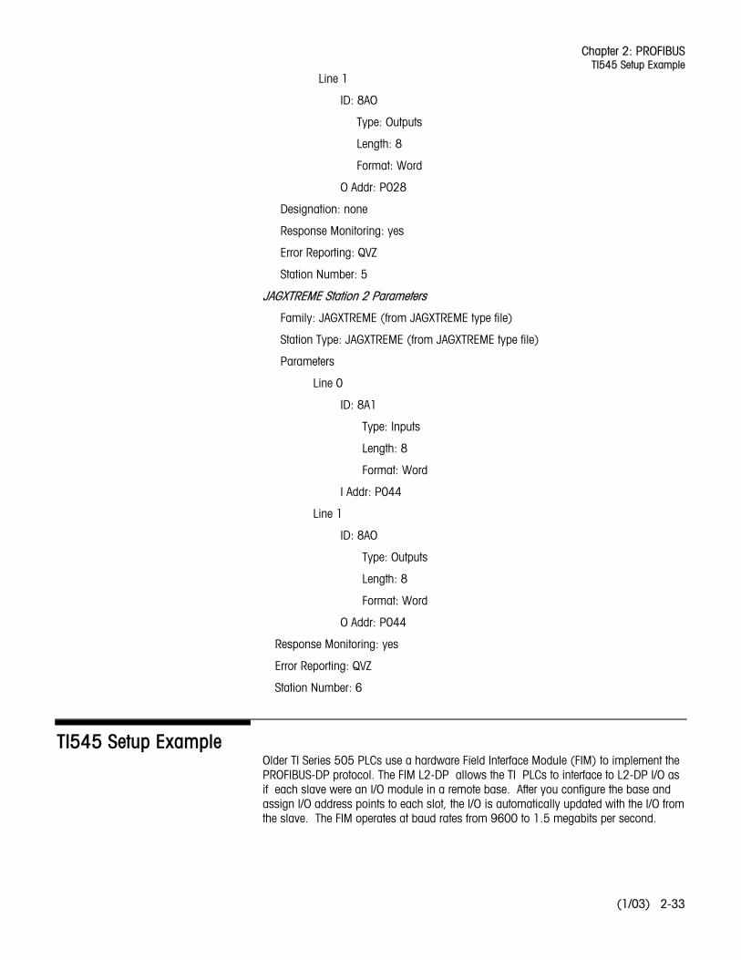
Chapter 2: PROFIBUS TI545 Setup Example
Line 1
ID: 8AO
Type: Outputs
Length: 8
Format: Word
O Addr: P028
Designation: none
Response Monitoring: yes
Error Reporting: QVZ
Station Number: 5
JAGXTREME Station 2 Parameters
Family: JAGXTREME (from JAGXTREME type file)
Station Type: JAGXTREME (from JAGXTREME type file)
Parameters
Line 0
ID: 8A1
Type: Inputs
Length: 8
Format: Word
I Addr: P044
Line 1
ID: 8AO
Type: Outputs
Length: 8
Format: Word
O Addr: P044
Response Monitoring: yes
Error Reporting: QVZ
Station Number: 6
TI545 Setup Example Older TI Series 505 PLCs use a hardware Field Interface Module (FIM) to implement the PROFIBUS-DP protocol. The FIM L2-DP allows the TI PLCs to interface to L2-DP I/O as if each slave were an I/O module in a remote base. After you configure the base and assign I/O address points to each slot, the I/O is automatically updated with the I/O from the slave. The FIM operates at baud rates from 9600 to 1.5 megabits per second.
(1/03)
2-33
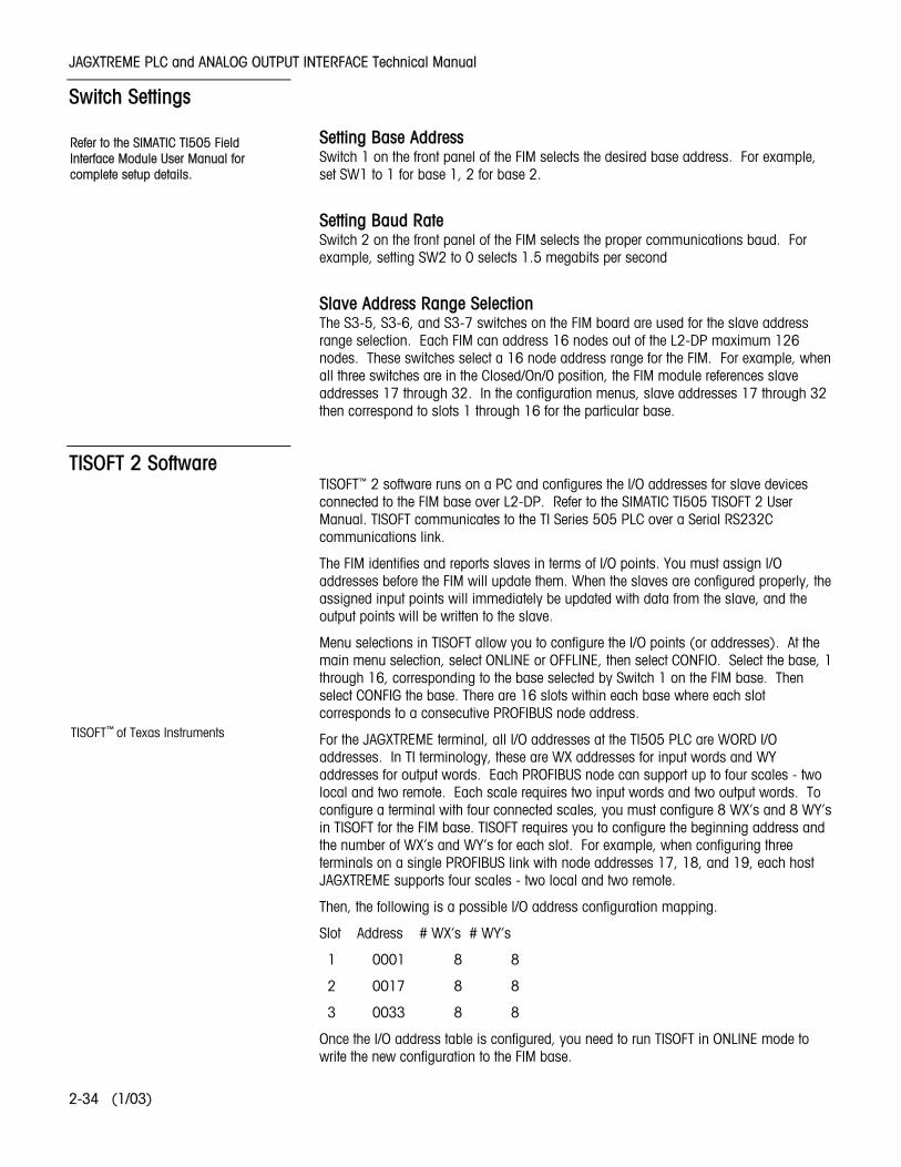
JAGXTREME PLC and ANALOG OUTPUT INTERFACE Technical Manual
Switch Settings
Setting Base Address Refer to the SIMATIC TI505 Field Interface Module User Manual for complete setup details.
Switch 1 on the front panel of the FIM selects the desired base address. For example, set SW1 to 1 for base 1, 2 for base 2.
Setting Baud Rate Switch 2 on the front panel of the FIM selects the proper communications baud. For example, setting SW2 to 0 selects 1.5 megabits per second
Slave Address Range Selection The S3-5, S3-6, and S3-7 switches on the FIM board are used for the slave address range selection. Each FIM can address 16 nodes out of the L2-DP maximum 126 nodes. These switches select a 16 node address range for the FIM. For example, when all three switches are in the Closed/On/0 position, the FIM module references slave addresses 17 through 32. In the configuration menus, slave addresses 17 through 32 then correspond to slots 1 through 16 for the particular base.
TISOFT 2 Software TISOFT™ 2 software runs on a PC and configures the I/O addresses for slave devices connected to the FIM base over L2-DP. Refer to the SIMATIC TI505 TISOFT 2 User Manual. TISOFT communicates to the TI Series 505 PLC over a Serial RS232C communications link.
The FIM identifies and reports slaves in terms of I/O points. You must assign I/O addresses before the FIM will update them. When the slaves are configured properly, the assigned input points will immediately be updated with data from the slave, and the output points will be written to the slave.
Menu selections in TISOFT allow you to configure the I/O points (or addresses). At the main menu selection, select ONLINE or OFFLINE, then select CONFIO. Select the base, 1 through 16, corresponding to the base selected by Switch 1 on the FIM base. Then select CONFIG the base. There are 16 slots within each base where each slot corresponds to a consecutive PROFIBUS node address.
TISOFT™ of Texas Instruments For the JAGXTREME terminal, all I/O addresses at the TI505 PLC are WORD I/O addresses. In TI terminology, these are WX addresses for input words and WY addresses for output words. Each PROFIBUS node can support up to four scales - two local and two remote. Each scale requires two input words and two output words. To configure a terminal with four connected scales, you must configure 8 WX’s and 8 WY’s in TISOFT for the FIM base. TISOFT requires you to configure the beginning address and the number of WX’s and WY’s for each slot. For example, when configuring three terminals on a single PROFIBUS link with node addresses 17, 18, and 19, each host JAGXTREME supports four scales - two local and two remote.
Then, the following is a possible I/O address configuration mapping.
Slot Address # WX’s # WY’s
1 0001 8 8
2 0017 8 8
3 0033 8 8
Once the I/O address table is configured, you need to run TISOFT in ONLINE mode to write the new configuration to the FIM base.
(1/03) 2-34
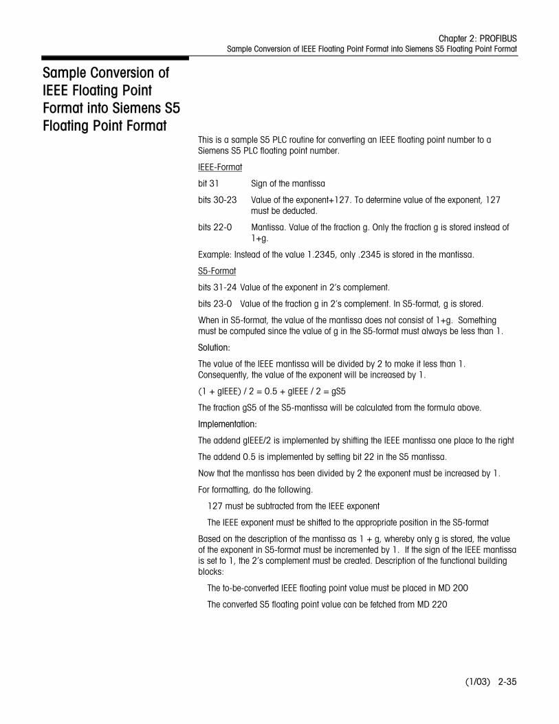
Chapter 2: PROFIBUS Sample Conversion of IEEE Floating Point Format into Siemens S5 Floating Point Format
Sample Conversion of IEEE Floating Point Format into Siemens S5 Floating Point Format
This is a sample S5 PLC routine for converting an IEEE floating point number to a Siemens S5 PLC floating point number.
IEEE-Format
bit 31 Sign of the mantissa
bits 30-23 Value of the exponent+127. To determine value of the exponent, 127 must be deducted.
bits 22-0 Mantissa. Value of the fraction g. Only the fraction g is stored instead of 1+g.
Example: Instead of the value 1.2345, only .2345 is stored in the mantissa.
S5-Format
bits 31-24 Value of the exponent in 2’s complement.
bits 23-0 Value of the fraction g in 2’s complement. In S5-format, g is stored.
When in S5-format, the value of the mantissa does not consist of 1+g. Something must be computed since the value of g in the S5-format must always be less than 1.
Solution:
The value of the IEEE mantissa will be divided by 2 to make it less than 1. Consequently, the value of the exponent will be increased by 1.
(1 + gIEEE) / 2 = 0.5 + gIEEE / 2 = gS5
The fraction gS5 of the S5-mantissa will be calculated from the formula above.
Implementation:
The addend gIEEE/2 is implemented by shifting the IEEE mantissa one place to the right
The addend 0.5 is implemented by setting bit 22 in the S5 mantissa.
Now that the mantissa has been divided by 2 the exponent must be increased by 1.
For formatting, do the following.
127 must be subtracted from the IEEE exponent
The IEEE exponent must be shifted to the appropriate position in the S5-format
Based on the description of the mantissa as 1 + g, whereby only g is stored, the value of the exponent in S5-format must be incremented by 1. If the sign of the IEEE mantissa is set to 1, the 2’s complement must be created. Description of the functional building blocks:
The to-be-converted IEEE floating point value must be placed in MD 200
The converted S5 floating point value can be fetched from MD 220
(1/03)
2-35
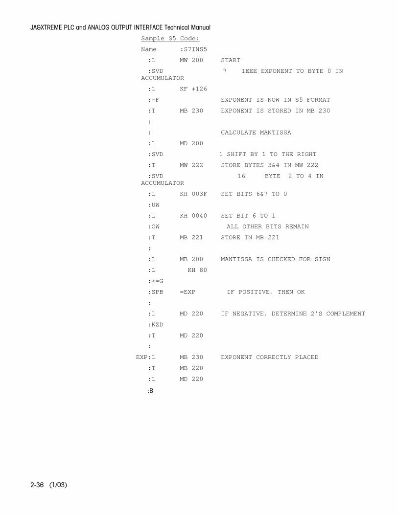
JAGXTREME PLC and ANALOG OUTPUT INTERFACE Technical Manual
Sample S5 Code:
Name :S7INS5
:L MW 200 START
:SVD 7 IEEE EXPONENT TO BYTE 0 IN ACCUMULATOR
:L KF +126
:-F EXPONENT IS NOW IN S5 FORMAT
:T MB 230 EXPONENT IS STORED IN MB 230
:
: CALCULATE MANTISSA
:L MD 200
:SVD 1 SHIFT BY 1 TO THE RIGHT
:T MW 222 STORE BYTES 3&4 IN MW 222
:SVD 16 BYTE 2 TO 4 IN ACCUMULATOR
:L KH 003F SET BITS 6&7 TO 0
:UW
:L KH 0040 SET BIT 6 TO 1
:OW ALL OTHER BITS REMAIN
:T MB 221 STORE IN MB 221
:
:L MB 200 MANTISSA IS CHECKED FOR SIGN
:L KH 80
:<=G
:SPB =EXP IF POSITIVE, THEN OK
:
:L MD 220 IF NEGATIVE, DETERMINE 2’S COMPLEMENT
:KZD
:T MD 220
:
EXP:L MB 230 EXPONENT CORRECTLY PLACED
:T MB 220
:L MD 220
:B
(1/03) 2-36
Chapter 3: Dual Analog Output Option Card JAGXTREME Terminal Dual Analog Output PCB
3 Dual Analog Output Option Card
JAGXTREME Terminal Dual Analog Output PCB
WARNING
WHEN THIS EQUIPMENT IS INCLUDED AS A COMPONENT PART OF A SYSTEM, THE DESIGN MUST BE REVIEWED BY QUALIFIED PERSONNEL WHO ARE FAMILIAR WITH THE CONSTRUCTION AND OPERATION OF ALL COMPONENTS IN THE SYSTEM AND THE POTENTIAL HAZARDS INVOLVED. FAILURE TO OBSERVE THIS PRECAUTION COULD RESULT IN BODILY INJURY.
The Dual Analog Output option kit provides a two-channel isolated 4-20 mA or 0-10 VDC analog signal output for gross weight or displayed weight. The outputs will be low when the displayed weight is at zero. When the displayed weight reaches maximum capacity, the outputs will increase to the maximum (20 mA or 10 VDC). Any weight between zero and full capacity will be represented as a percentage of the output proportional to the percentage of full scale capacity.
The Analog Output sub-block lets you select the data source and calibrate analog zero and full-scale values. The JAGXTREME terminal must be calibrated to the desired scale before making Analog Output adjustments. The Analog Output card has two channels. Channel 1 is typically assigned to Scale 1; Channel 2 to Scale 2 (if a second scale is being used). In setup, you can assign the scale source of the analog output values to the output channel.
Data sources may be weight, rate, or JAGBASIC output.
Specifications Maximum Cable Length: 0-10 VDC - 50 ft (15.2 m)
4-20mA – 1000 ft (300 m)
Recommended Load: Note: If the load resistance ratings are exceeded, the analog output will not operate properly. Resistance: 0-10 VDC - 100k ohms minimum
4-20 mA - 500 ohms maximum
Outputs: 2 channels capable of supplying 4-20 mA or 0-10 VDC.
(1-03) 3-1
JAGXTREME PLC and Analog Output Interface Technical Manual
Installation
WARNING DISCONNECT ALL POWER TO THIS UNIT BEFORE REMOVING THE FUSE OR SERVICING.
CAUTION OBSERVE PRECAUTIONS FOR HANDLING ELECTROSTATIC SENSITIVE DEVICES.
WARNING DO NOT APPLY POWER TO THE JAGXTREME TERMINAL UNTIL INSTALLATION OF COMPONENTS AND EXTERNAL WIRING HAVE BEEN COMPLETED.
To install the Analog Output option card in the JAGXTREME terminal:
• Disconnect AC power to the JAGXTREME terminal.
• Remove the JAGXTREME terminal rear panel if installing in a general purpose or harsh environment unit. On the panel mount version only, remove the cover plate from an open slot on the rear of the JAGXTREME terminal.
• Insert the Analog Output option card in an open slot in the rear of the terminal. Seat the card by inserting it into the slot, then tighten the thumbscrews finger tight.
• Connect the external wiring to the Analog Output card outputs.
• Install the rear covers on the general purpose or harsh environment versions.
• Power up the terminal. The JAGXTREME terminal will recognize the new option card automatically.
3-2 (1-03)
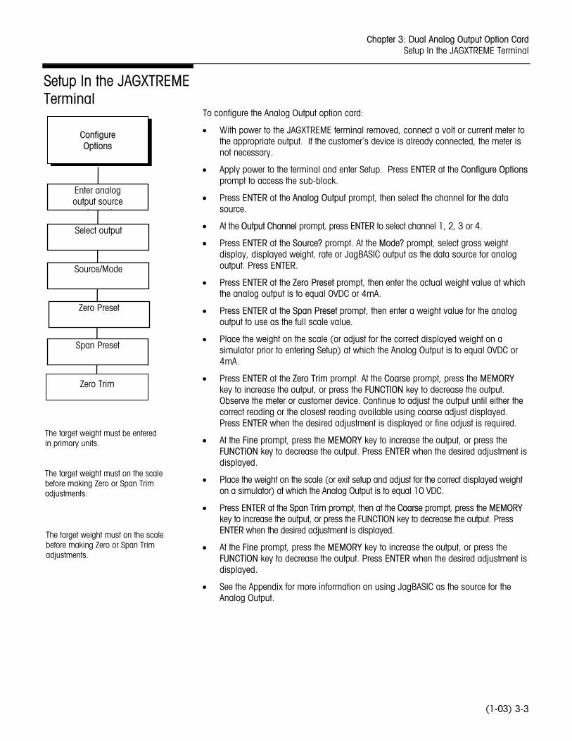
Chapter 3: Dual Analog Output Option Card Setup In the JAGXTREME Terminal
Setup In the JAGXTREME Terminal
To configure the Analog Output option card:
Zero Trim
Enter analog output source
h l
Span Preset
Zero Preset
Source/Mode
Select output
Configure Options
• With power to the JAGXTREME terminal removed, connect a volt or current meter to the appropriate output. If the customer’s device is already connected, the meter is not necessary.
• Apply power to the terminal and enter Setup. Press ENTER at the Configure Options prompt to access the sub-block.
• Press ENTER at the Analog Output prompt, then select the channel for the data source.
• At the Output Channel prompt, press ENTER to select channel 1, 2, 3 or 4.
• Press ENTER at the Source? prompt. At the Mode? prompt, select gross weight display, displayed weight, rate or JagBASIC output as the data source for analog output. Press ENTER.
• Press ENTER at the Zero Preset prompt, then enter the actual weight value at which the analog output is to equal 0VDC or 4mA.
• Press ENTER at the Span Preset prompt, then enter a weight value for the analog output to use as the full scale value.
• Place the weight on the scale (or adjust for the correct displayed weight on a simulator prior to entering Setup) at which the Analog Output is to equal 0VDC or 4mA.
• Press ENTER at the Zero Trim prompt. At the Coarse prompt, press the MEMORY key to increase the output, or press the FUNCTION key to decrease the output. Observe the meter or customer device. Continue to adjust the output until either the correct reading or the closest reading available using coarse adjust displayed. Press ENTER when the desired adjustment is displayed or fine adjust is required.
The target weight must be entered in primary units. The target weight must on the scale before making Zero or Span Trim adjustments.
• At the Fine prompt, press the MEMORY key to increase the output, or press the FUNCTION key to decrease the output. Press ENTER when the desired adjustment is displayed.
• Place the weight on the scale (or exit setup and adjust for the correct displayed weight on a simulator) at which the Analog Output is to equal 10 VDC.
• Press ENTER at the Span Trim prompt, then at the Coarse prompt, press the MEMORY key to increase the output, or press the FUNCTION key to decrease the output. Press ENTER when the desired adjustment is displayed. The target weight must on the scale
before making Zero or Span Trim adjustments.
• At the Fine prompt, press the MEMORY key to increase the output, or press the FUNCTION key to decrease the output. Press ENTER when the desired adjustment is displayed.
• See the Appendix for more information on using JagBASIC as the source for the Analog Output.
(1-03) 3-3
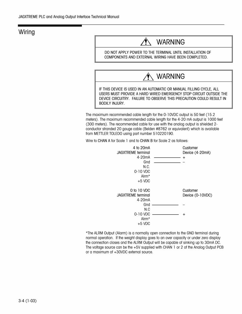
JAGXTREME PLC and Analog Output Interface Technical Manual
Wiring
WARNING DO NOT APPLY POWER TO THE TERMINAL UNTIL INSTALLATION OF
COMPONENTS AND EXTERNAL WIRING HAVE BEEN COMPLETED.
WARNING
IF THIS DEVICE IS USED IN AN AUTOMATIC OR MANUAL FILLING CYCLE, ALL USERS MUST PROVIDE A HARD WIRED EMERGENCY STOP CIRCUIT OUTSIDE THE DEVICE CIRCUITRY. FAILURE TO OBSERVE THIS PRECAUTION COULD RESULT IN BODILY INJURY.
The maximum recommended cable length for the 0-10VDC output is 50 feet (15.2 meters). The maximum recommended cable length for the 4-20 mA output is 1000 feet (300 meters). The recommended cable for use with the analog output is shielded 2-conductor stranded 20 gauge cable (Belden #8762 or equivalent) which is available from METTLER TOLEDO using part number 510220190.
Wire to CHAN A for Scale 1 and to CHAN B for Scale 2 as follows:
4 to 20mA Customer JAGXTREME terminal Device (4-20mA)
4-20mA + Gnd – N.C.
0-10 VDC Alrm*
+5 VDC
0 to 10 VDC Customer JAGXTREME terminal Device (0-10VDC)
4-20mA Gnd – N.C
0-10 VDC + Alrm*
+5 VDC
*The ALRM Output (Alarm) is a normally open connection to the GND terminal during normal operation. If the weight display goes to an over capacity or under zero display the connection closes and the ALRM Output will be capable of sinking up to 30mA DC. The voltage source can be the +5V supplied with CHAN 1 or 2 of the Analog Output PCB or a maximum of +30VDC external source.
3-4 (1-03)
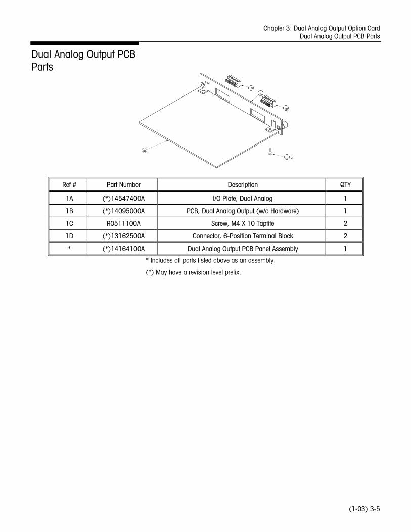
Chapter 3: Dual Analog Output Option Card Dual Analog Output PCB Parts
Dual Analog Output PCB Parts
1D
1A
1D
1C 2
1B
Ref # Part Number Description QTY
1A (*)14547400A I/O Plate, Dual Analog 1
1B (*)14095000A PCB, Dual Analog Output (w/o Hardware) 1
1C R0511100A Screw, M4 X 10 Taptite 2
1D (*)13162500A Connector, 6-Position Terminal Block 2
* (*)14164100A Dual Analog Output PCB Panel Assembly 1
* Includes all parts listed above as an assembly.
(*) May have a revision level prefix.
(1-03) 3-5

JAGXTREME PLC and Analog Output Interface Technical Manual
For your notes
3-6 (1-03)
Chapter 4: Modbus Plus Option Card Overview
4 Modbus Plus Option Card
Overview Modbus Plus is a local area network designed for industrial control applications. The network enables Modicon Model 984 programmable controllers, host computers, JAGXTREME terminals, PANTHER terminals, and other devices to communicate throughout the production areas of an industrial plant. It supports 64 addressable node devices at a data transfer rate of one million bits per second. Up to 32 devices can connect directly to a network cable with a length of up to 1500 feet.
The JAGXTREME Modbus Plus interface is an option card that plugs into the JAGXTREME terminal. It has a “peer processor” that implements the network protocol; an FM encoder/decoder; and an RS485 driver that provides the interface to the Modbus Plus network. The interface card is a single Modbus Plus node. The hosting JAGXTREME terminal can support up to four scales within the node. The scales can be any combination of local or remote scales in a JAGXTREME terminal cluster.
Communication Point-to-point communication in the Modbus Plus network is the communication between two network nodes. The “Master Task” at the PLC initiating node generates a “transaction query” for the “Slave Command Handler Task” at the destination JAGXTREME node. The Slave Command Handler Task sends a “transaction response” to the transaction query. Peer Processors route the messages through the network.
The Modbus Plus PLC acts as the Master Task. The JAGXTREME terminal has the Slave Command Handler Task. The PLC initiates all transactions. The JAGXTREME terminal responds to the transaction queries.
The general format for Modbus transaction query command is a one-byte command followed by a group of data or function bytes. The maximum message length is 252 bytes. The function bytes tell the slave device what action to perform.
The JAGXTREME terminal supports the following Modbus functions:
03 Read Holding Registers This function requests the value of one or more 16-bit holding registers.
16 Preset Multiple Registers Place values into a series of consecutive holding registers.
The transaction query messages contain register values that specify what data that the PLC is requesting from the JAGXTREME terminal. For example, if the PLC issues Function 03, the data field must contain information telling the JAGXTREME terminal what register number to start at and how many registers to read. All address references within the Modbus messages are relative to zero. For example, the first holding register in the Modicon 984 PLC is 40001, but has the value 0000 in the messages.
The JAGXTREME terminal must be set up in one of the “integer” weight data modes or in the “floating point” weight data mode. These modes are mutually exclusive, that is, the Modicon PLC can request either integer weight data or the floating point weight data, but cannot request both interchangeably in the same JAGXTREME terminal setup.
(02/05) 4-1
JAGXTREME PLC and Analog Output Interface Technical Manual
Node/Rack Address Each Modbus Plus option card represents one physical node but may contain data for multiple scales. The node address is chosen by the system designer, setup in the terminal, and programmed into the PLC. The JAGXTREME terminal’s node address is set up via the DIP switches located on the Modbus Plus Option card. The node address and input and output registers used to communicate between the terminal and the PLC are programmed into the PLC by using its programming software (using MSTR function). The terminal setup capabilities allow viewing of the logical rack (node) address and selection of data format and number of scales using the node. The terminal will determine the number of input and output registers needed for the number of configured scales and chosen data format. The PLC must be configured to use the same amount of space and the correct registers in the MSTR function for the appropriate data format.
Data Formats The Modbus Plus option card has two types of data exchanges: discrete data and shared data. Each scale selected to pass data through the JAGXTREME terminal’s Modbus Plus option has its own input and output registers to communicate continuously with the PLC. Shared data access is used to pass information that cannot be sent by the discrete data because of size or process speed limitations and uses additional input and output register space. See the Data Definition section for information on the available data formats.
Remote Scale Sharing The JAGXTREME terminal’s Ethernet feature makes it possible for a JAGXTREME terminal to communicate with other JAGXTREME terminals and to share resources. This allows one terminal with the Modbus Plus option card to collect information from up to four networked and local scales when using any of its data formats. The Ethernet connection also allows the terminal to share information with other networked equipment.
(02/05) 4-2
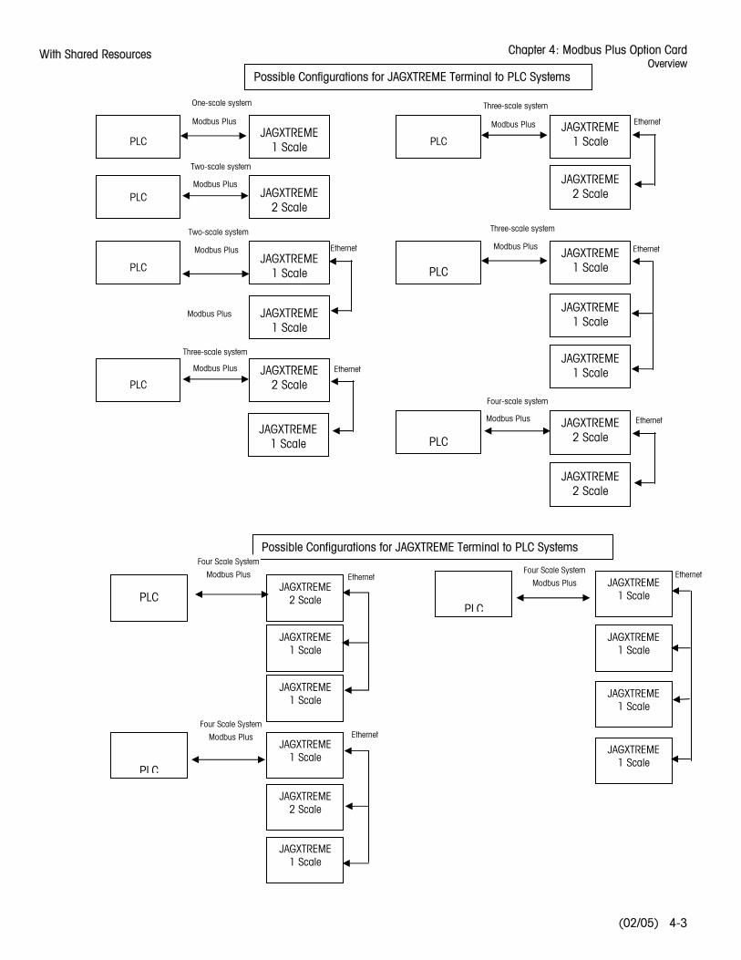
Chapter 4: Modbus Plus Option Card Overview
Possible Configurations for JAGXTREME Terminal to PLC Systems
With Shared Resources
Three-scale system
JAGXTREME 1 Scale
JAGXTREME 1 Scale
JAGXTREME 1 Scale
Ethernet
Modbus Plus
PLC
Three-scale system
Modbus Plus
Two-scale system
Two-scale system
PLC
Modbus Plus
Three-scale system
PLC
JAGXTREME 1 Scale
JAGXTREME 1 Scale
JAGXTREME 1 Scale
Ethernet
JAGXTREME 2 Scale
JAGXTREME 1 Scale
Ethernet
Modbus Plus
Modbus Plus
Modbus Plus
Modbus Plus
Ethernet
PLC
JAGXTREME 1 Scale
PLC
PLC
JAGXTREME 2 Scale
JAGXTREME 2 Scale
PLC
JAGXTREME 2 Scale
Ethernet Modbus Plus
Four-scale system
One-scale system
JAGXTREME 2 Scale
PLC
JAGXTREME 1 Scale
JAGXTREME 1 Scale
JAGXTREME 1 Scale
JAGXTREME 1 Scale
JAGXTREME 1 Scale
JAGXTREME 2 Scale
JAGXTREME 1 Scale
JAGXTREME 2 Scale
JAGXTREME 1 Scale
JAGXTREME 1 Scale
Four Scale System
Modbus Plus
Four Scale System
Modbus Plus
Four Scale System
Modbus Plus Ethernet
Ethernet Ethernet
Possible Configurations for JAGXTREME Terminal to PLC Systems
PLC
PLC
(02/05) 4-3
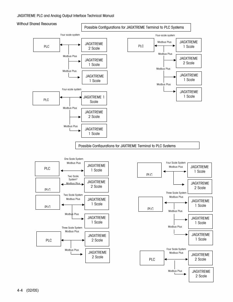
JAGXTREME PLC and Analog Output Interface Technical Manual
(02/05) 4-4
Without Shared Resources
PLC
PLC
Modbus Plus
PLC
Modbus Plus
Three Scale System
Modbus Plus
Two Scale System
Modbus Plus
One Scale System
Modbus Plus
PLC
Possible Configurations for JAGXTREME Terminal to PLC Systems
Four-scale system Four-scale system
JAGXTREME 1 Scale
Four-scale system
Modbus Plus
Modbus Plus
JAGXTREME 2 Scale
PLC
JAGXTREME 2 Scale
Modbus Plus
Modbus Plus
JAGXTREME 1 Scale
JAGXTREME 1 Scale
PLC
JAGXTREME 2 Scale
JAGXTREME 1 Scale
JAGXTREME 1 Scale
Modbus Plus
Modbus Plus
Modbus Plus
JAGXTREME 1 Scale
PLC
Modbus Plus
JAGXTREME 1 Scale
JAGXTREME 1 Scale
JAGXTREME
PLC
JAGXTREME 1 Scale
Four Scale System
Modbus Plus
Two Scale System*
Modbus Plus
JAGXTREME 1 Scale
JAGXTREME 2 Scale
JAGXTREME 2 Scale
JAGXTREME 1 Scale
2 Scale JAGXTREME
2 Scale
JAGXTREME 1 Scale
JAGXTREME 1 Scale
Three Scale System
Modbus Plus
PLC
JAGXTREME 1 Scale
Four Scale System
Modbus Plus
Modbus Plus
Modbus Plus
Modbus Plus
PLC
JAGXTREME2 Scale
JAGXTREME 2 Scale
Possible Configurations for JAXTREME Terminal to PLC Systems
Chapter 4: Modbus Plus Option Card Data Definition
Data Definition The JAGXTREME terminal’s Modbus Plus option card uses two types of data for communicating with the PLC, discrete data and shared data. Separate discrete data for each scale is always available. The data transfer is accomplished via the PLCs MSTR function (or use of the global data functionality). If the shared data is used, it is provided in addition to the discrete data for each scale.
Data Integrity The JAGXTREME terminal has specific bits to allow the PLC to confirm that the data was received without interruption and with the scale not in an error condition. It is important to monitor these bits. Any PLC code should use them to confirm the integrity of the data received for the scale. Refer to the detailed data charts for specific information regarding the Data OK, update in progress, and data integrity bits and their usage.
Discrete Data There are four formats of discrete data available with the Modbus Plus option card. Only one data format may be selected and used by scales sharing the same card.
• The integer (wgt) and division (div) formats allow bi-directional communication of discrete bit encoded information or 16-bit binary word (signed integer) numerical values.
• The extended (ext) integer format allows bi-directional communication of discrete bit encoded information, 21-bit binary word (signed extended integer) numerical read values or 16-bit binary word (signed integer) numerical write values.
• The floating point (flt) format allows bi-directional communication of discrete bit encoded information or numeric data encoded in IEEE 754, single precision floating point format.
The format of discrete data affects the amount of input/output register space required per scale and the total input/output registers used by the Modbus Plus option card. Integer, division, and extended integer formats require two 16-bit words of input and two16-bit words of output data per scale. One scale would use two 16-bit registers of input and two 16-bit registers of output. Two scales would use four16-bit registers of input and four 16-bit registers of output. Three scales would use six 16-bit registers of input and six 16-bit registers of output. Four scales would use eight 16-bit registers of input and eight 16-bit registers of output.
The floating point format requires more space per scale because floating point data uses two 16-bit words of data to represent just the numeric data. The floating point format requires four 16-bit registers of input and four 16-bit registers of output data per scale. The smallest amount that the terminal can configure for floating point is eight registers of input and eight registers of output. This means that when a single scale is configured, there are two sets of input/output data for the scale. Four scales using the floating point format would use 16 registers of input and 16 registers of output data. Shared data would require additional space, if used.
Format selection depends on different issues. First, the range or capacity of the scale used in the application should be considered. The integer format can represent a numerical value of up to 32,767; the division format can represent a numerical value of up to 32,767 divisions (or increments); the extended integer can represent a numerical value of over 1,000,000; and the floating point format can represent a numerical value encoded in IEEE 754, single precision floating point format.
(02/05) 4-5
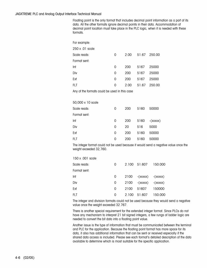
JAGXTREME PLC and Analog Output Interface Technical Manual
Floating point is the only format that includes decimal point information as a part of its data. All the other formats ignore decimal points in their data. Accommodation of decimal point location must take place in the PLC logic, when it is needed with these formats.
For example:
250 x .01 scale
Scale reads: 0 2.00 51.67 250.00
Format sent:
Int 0 200 5167 25000
Div 0 200 5167 25000
Ext 0 200 5167 25000
FLT 0 2.00 51.67 250.00
Any of the formats could be used in this case
50,000 x 10 scale
Scale reads: 0 200 5160 50000
Format sent:
Int 0 200 5160 -(xxxxx)
Div 0 20 516 5000
Ext 0 200 5160 50000
FLT 0 200 5160 50000
The integer format could not be used because it would send a negative value once the weight exceeded 32,760.
150 x .001 scale
Scale reads: 0 2.100 51.607 150.000
Format sent:
Int 0 2100 -(xxxxx) -(xxxxx)
Div 0 2100 -(xxxxx) -(xxxxx)
Ext 0 2100 51607 150000
FLT 0 2.100 51.607 150.000
The integer and division formats could not be used because they would send a negative value once the weight exceeded 32.767.
There is another special requirement for the extended integer format. Since PLCs do not have any mechanism to interpret 21 bit signed integers, a few rungs of ladder logic are needed to convert the bit data into a floating point value.
Another issue is the type of information that must be communicated between the terminal and PLC for the application. Because the floating point format has more space for its data, it also has additional information that can be sent or received especially if the shared data access is included. Please see each format’s detailed description of the data available to determine which is most suitable for the specific application.
(02/05) 4-6
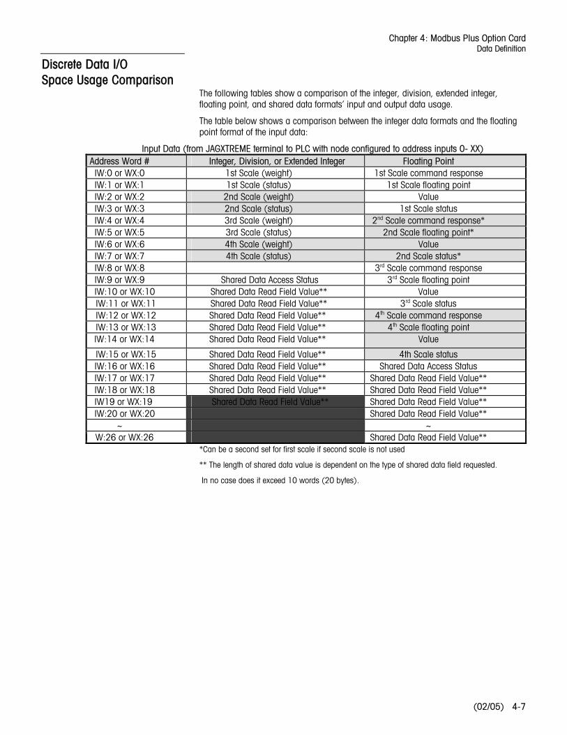
Chapter 4: Modbus Plus Option Card Data Definition
Discrete Data I/O Space Usage Comparison
The following tables show a comparison of the integer, division, extended integer, floating point, and shared data formats’ input and output data usage.
The table below shows a comparison between the integer data formats and the floating point format of the input data:
Input Data (from JAGXTREME terminal to PLC with node configured to address inputs 0- XX) Address Word # Integer, Division, or Extended Integer Floating Point IW:0 or WX:0 1st Scale (weight) 1st Scale command response IW:1 or WX:1 1st Scale (status) 1st Scale floating point IW:2 or WX:2 2nd Scale (weight) Value IW:3 or WX:3 2nd Scale (status) 1st Scale status IW:4 or WX:4 3rd Scale (weight) 2nd Scale command response* IW:5 or WX:5 3rd Scale (status) 2nd Scale floating point* IW:6 or WX:6 4th Scale (weight) Value IW:7 or WX:7 4th Scale (status) 2nd Scale status* IW:8 or WX:8 3rd Scale command response IW:9 or WX:9 Shared Data Access Status 3rd Scale floating point
IW:10 or WX:10 Shared Data Read Field Value** Value IW:11 or WX:11 Shared Data Read Field Value** 3rd Scale status IW:12 or WX:12 Shared Data Read Field Value** 4th Scale command response IW:13 or WX:13 Shared Data Read Field Value** 4th Scale floating point IW:14 or WX:14 Shared Data Read Field Value** Value
IW:15 or WX:15 Shared Data Read Field Value** 4th Scale status IW:16 or WX:16 Shared Data Read Field Value** Shared Data Access Status IW:17 or WX:17 Shared Data Read Field Value** Shared Data Read Field Value** IW:18 or WX:18 Shared Data Read Field Value** Shared Data Read Field Value** IW19 or WX:19 Shared Data Read Field Value** Shared Data Read Field Value** IW:20 or WX:20 Shared Data Read Field Value**
~ ~ I W:26 or WX:26 Shared Data Read Field Value**
*Can be a second set for first scale if second scale is not used
** The length of shared data value is dependent on the type of shared data field requested.
In no case does it exceed 10 words (20 bytes).
(02/05) 4-7
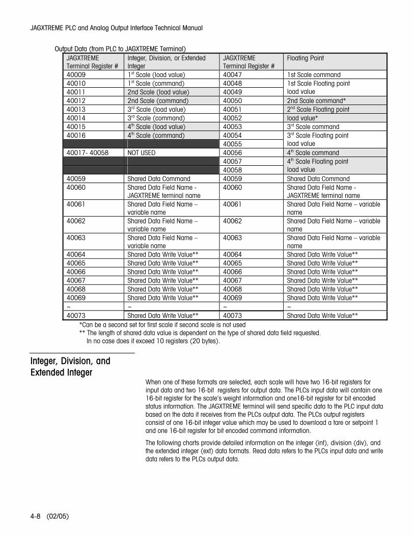
JAGXTREME PLC and Analog Output Interface Technical Manual
4-8 (02/05)
Output Data (from PLC to JAGXTREME Terminal)
JAGXTREME Terminal Register #
Integer, Division, or Extended Integer
JAGXTREME Terminal Register #
Floating Point
40009 1st Scale (load value) 40047 1st Scale command 40010 1st Scale (command) 40048 40011 2nd Scale (load value) 40049
1st Scale Floating point load value
40012 2nd Scale (command) 40050 2nd Scale command* 40013 3rd Scale (load value) 40051 2nd Scale Floating point 40014 3rd Scale (command) 40052 load value* 40015 4th Scale (load value) 40053 3rd Scale command 40016 4th Scale (command) 40054 40055
3rd Scale Floating point load value
40017- 40058 NOT USED 40056 4th Scale command 40057 40058
4th Scale Floating point load value
40059 Shared Data Command 40059 Shared Data Command 40060 Shared Data Field Name -
JAGXTREME terminal name 40060 Shared Data Field Name -
JAGXTREME terminal name 40061 Shared Data Field Name –
variable name 40061 Shared Data Field Name – variable
name 40062 Shared Data Field Name –
variable name 40062 Shared Data Field Name – variable
name 40063 Shared Data Field Name –
variable name 40063 Shared Data Field Name – variable
name 40064 Shared Data Write Value** 40064 Shared Data Write Value** 40065 Shared Data Write Value** 40065 Shared Data Write Value** 40066 Shared Data Write Value** 40066 Shared Data Write Value** 40067 Shared Data Write Value** 40067 Shared Data Write Value** 40068 Shared Data Write Value** 40068 Shared Data Write Value** 40069 Shared Data Write Value** 40069 Shared Data Write Value** ~ ~ ~ ~ 40073 Shared Data Write Value** 40073 Shared Data Write Value**
*Can be a second set for first scale if second scale is not used ** The length of shared data value is dependent on the type of shared data field requested. In no case does it exceed 10 registers (20 bytes).
Integer, Division, and Extended Integer
When one of these formats are selected, each scale will have two 16-bit registers for input data and two 16-bit registers for output data. The PLCs input data will contain one 16-bit register for the scale’s weight information and one16-bit register for bit encoded status information. The JAGXTREME terminal will send specific data to the PLC input data based on the data it receives from the PLCs output data. The PLCs output registers consist of one 16-bit integer value which may be used to download a tare or setpoint 1 and one 16-bit register for bit encoded command information.
The following charts provide detailed information on the integer (int), division (div), and the extended integer (ext) data formats. Read data refers to the PLCs input data and write data refers to the PLCs output data.
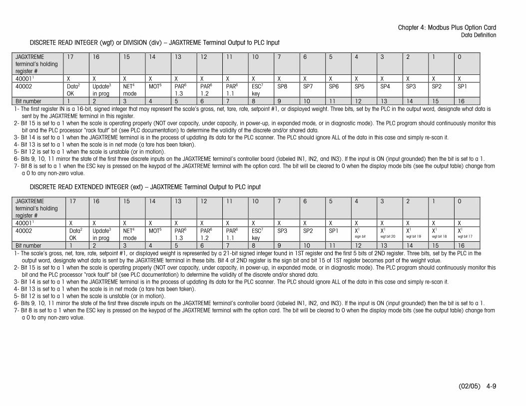
Chapter 4: Modbus Plus Option Card Data Definition
DISCRETE READ INTEGER (wgt) or DIVISION (div) – JAGXTREME Terminal Output to PLC Input
JAGXTREME terminal’s holding register #
17 16 15 14 13 12 11 10 7 6 5 4 3 2 1 0
400011 X X X X X X X X X X X X X X X X40002
Data2 OK
Update3 in prog
NET4 mode
MOT5 PAR6 1.3
PAR6 1.2
PAR6 1.1
ESC7
key SP8 SP7 SP6 SP5 SP4 SP3 SP2 SP1
Bit number 1 2 3 4 5 6 7 8 9 10 11 12 13 14 15 16 1- The first register IN is a 16-bit, signed integer that may represent the scale’s gross, net, tare, rate, setpoint #1, or displayed weight. Three bits, set by the PLC in the output word, designate what data is
sent by the JAGXTREME terminal in this register. 2- Bit 15 is set to a 1 when the scale is operating properly (NOT over capacity, under capacity, in power-up, in expanded mode, or in diagnostic mode). The PLC program should continuously monitor this
bit and the PLC processor “rack fault” bit (see PLC documentation) to determine the validity of the discrete and/or shared data. 3- Bit 14 is set to a 1 when the JAGXTREME terminal is in the process of updating its data for the PLC scanner. The PLC should ignore ALL of the data in this case and simply re-scan it. 4- Bit 13 is set to a 1 when the scale is in net mode (a tare has been taken). 5- Bit 12 is set to a 1 when the scale is unstable (or in motion). 6- Bits 9, 10, 11 mirror the state of the first three discrete inputs on the JAGXTREME terminal’s controller board (labeled IN1, IN2, and IN3). If the input is ON (input grounded) then the bit is set to a 1. 7- Bit 8 is set to a 1 when the ESC key is pressed on the keypad of the JAGXTREME terminal with the option card. The bit will be cleared to 0 when the display mode bits (see the output table) change from
a 0 to any non-zero value. DISCRETE READ EXTENDED INTEGER (ext) – JAGXTREME Terminal Output to PLC input
JAGXTREME terminal’s holding register #
17 16 15 14 13 12 11 10 7 6 5 4 3 2 1 0
400011 X X X X X X X X X X X X X X X X40002 Data2
OK Update3 in prog
NET4 mode
MOT5 PAR6 1.3
PAR6 1.2
PAR6 1.1
ESC7
key SP3 SP2 SP1 X1
sign bitX1
wgt bit 20X1
wgt bit 19X1
wgt bit 18X1
wgt bit 17
Bit number 1 2 3 4 5 6 7 8 9 10 11 12 13 14 15 16 1- The scale’s gross, net, tare, rate, setpoint #1, or displayed weight is represented by a 21-bit signed integer found in 1ST register and the first 5 bits of 2ND register. Three bits, set by the PLC in the
output word, designate what data is sent by the JAGXTREME terminal in these bits. Bit 4 of 2ND register is the sign bit and bit 15 of 1ST register becomes part of the weight value. 2- Bit 15 is set to a 1 when the scale is operating properly (NOT over capacity, under capacity, in power-up, in expanded mode, or in diagnostic mode). The PLC program should continuously monitor this
bit and the PLC processor “rack fault” bit (see PLC documentation) to determine the validity of the discrete and/or shared data. 3- Bit 14 is set to a 1 when the JAGXTREME terminal is in the process of updating its data for the PLC scanner. The PLC should ignore ALL of the data in this case and simply re-scan it. 4- Bit 13 is set to a 1 when the scale is in net mode (a tare has been taken). 5- Bit 12 is set to a 1 when the scale is unstable (or in motion). 6- Bits 9, 10, 11 mirror the state of the first three discrete inputs on the JAGXTREME terminal’s controller board (labeled IN1, IN2, and IN3). If the input is ON (input grounded) then the bit is set to a 1. 7- Bit 8 is set to a 1 when the ESC key is pressed on the keypad of the JAGXTREME terminal with the option card. The bit will be cleared to 0 when the display mode bits (see the output table) change from
a 0 to any non-zero value.
(02/05) 4-9
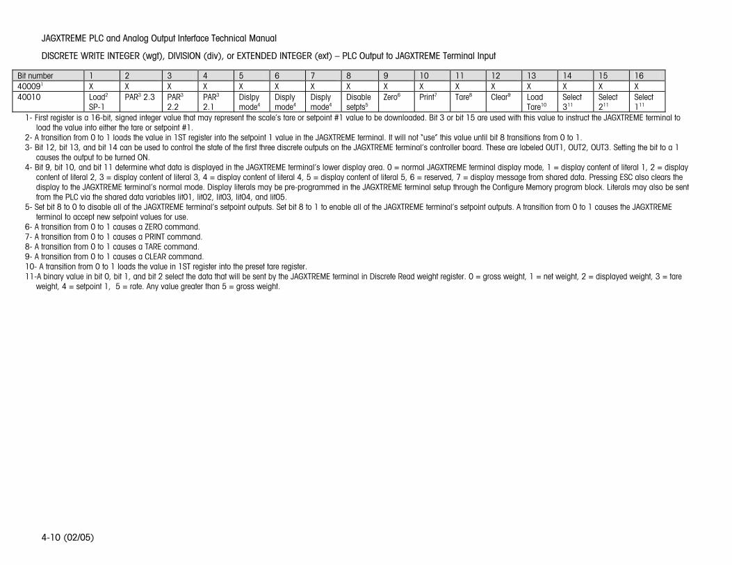
JAGXTREME PLC and Analog Output Interface Technical Manual
4-10
4- Bit 9, bit 10, and bit 11 determine what data is displayed in the JAGXTREME terminal’s lower display area. 0 = normal JAGXTREME terminal display mode, 1 = display content of literal 1, 2 = display content of literal 2, 3 = display content of literal 3, 4 = display content of literal 4, 5 = display content of literal 5, 6 = reserved, 7 = display message from shared data. Pressing ESC also clears the display to the JAGXTREME terminal’s normal mode. Display literals may be pre-programmed in the JAGXTREME terminal setup through the Configure Memory program block. Literals may also be sent from the PLC via the shared data variables lit01, lit02, lit03, lit04, and lit05.
11-A binary value in bit 0, bit 1, and bit 2 select the data that will be sent by the JAGXTREME terminal in Discrete Read weight register. 0 = gross weight, 1 = net weight, 2 = displayed weight, 3 = tare weight, 4 = setpoint 1, 5 = rate. Any value greater than 5 = gross weight.
(02/05)
DISCRETE WRITE INTEGER (wgt), DIVISION (div), or EXTENDED INTEGER (ext) – PLC Output to JAGXTREME Terminal Input
Bit number 1 2 3 4 5 6 7 8 9 10 11 12 13 14 15 16 400091 X X X X X X X X X X X X X X X X40010 Load2
SP-1 PAR3 2.3 PAR3
2.2 PAR3
2.1 Dislpy mode4
Disply mode4
Disply mode4
Disable setpts5
Zero6 Print7 Tare8 Clear9 Load Tare10
Select 311
Select 211
Select 111
1- First register is a 16-bit, signed integer value that may represent the scale’s tare or setpoint #1 value to be downloaded. Bit 3 or bit 15 are used with this value to instruct the JAGXTREME terminal to load the value into either the tare or setpoint #1.
3- Bit 12, bit 13, and bit 14 can be used to control the state of the first three discrete outputs on the JAGXTREME terminal’s controller board. These are labeled OUT1, OUT2, OUT3. Setting the bit to a 1 causes the output to be turned ON.
5- Set bit 8 to 0 to disable all of the JAGXTREME terminal’s setpoint outputs. Set bit 8 to 1 to enable all of the JAGXTREME terminal’s setpoint outputs. A transition from 0 to 1 causes the JAGXTREME terminal to accept new setpoint values for use.
2- A transition from 0 to 1 loads the value in 1ST register into the setpoint 1 value in the JAGXTREME terminal. It will not “use” this value until bit 8 transitions from 0 to 1.
10- A transition from 0 to 1 loads the value in 1ST register into the preset tare register. 9- A transition from 0 to 1 causes a CLEAR command.
7- A transition from 0 to 1 causes a PRINT command. 6- A transition from 0 to 1 causes a ZERO command.
8- A transition from 0 to 1 causes a TARE command.
Gross weight, net weight, and rate are examples of real-time data. Tare weight, setpoint cutoff, dribble, and tolerance values are examples of static data.
Floating Point
Operational Overview
Chapter 4: Modbus Plus Option Card Data Definition
(02/05) 4-11
The following charts provide detailed information on the floating point data format. Read data refers to the PLCs input data and write data refers to the PLCs output data.
When the PLC changes to the next command, the terminal switches to the next value in the rotation. The terminal stores the rotation in its shared data so the rotation does not have to be re-initialized after each power cycle. When the PLC does not set up an input rotation, the default input rotation consists of gross weight only.
The JAGXTREME terminal can send a rotation of up to nine different real-time values for each scale. In order to accomplish this, the PLC sends commands to the terminal to add a value to the rotation. Once the rotation is established, the PLC must instruct the terminal to begins its rotation automatically or the PLC may control the pace of rotation by instructing the terminal advance to the next value. If the terminal is asked to automatically alternate its output data, it will switch to the next value in its rotation at the next A/D update. (The A/D update rate depends on the scale type. An analog scale has an update rate of 17 Hz or 58 milliseconds.) The PLC may control the rotation by sending alternate report next field commands (1 and 2).
The JAGXTREME terminal has two types of values that it can report to the PLC: real-time and static. When the PLC requests a real-time value, the terminal will acknowledge the command from the PLC once but will send and update the value at every A/D update. However, if the PLC requests a static value, the terminal will acknowledge the command from the PLC once and update the value once. The terminal will continue to send this value until it receives a new command from the PLC.
The JAGXTREME terminal uses integer commands from the PLC to select the floating point weight output data. The terminal will recognize a command when it sees a new value in the scale’s command register. If the command has an associated floating point value (for example: loading a setpoint value), it must be loaded into the floating point value registers before the command is issued. Once the terminal recognizes a command, it will acknowledge the command by setting a new value in the command acknowledge bits of the scale’s command response register. It will also tell the PLC what floating point value is currently being sent (via the floating point input indicator bits of the command response register). The PLC will wait until it receives the command acknowledgment from the terminal before it sends another command.
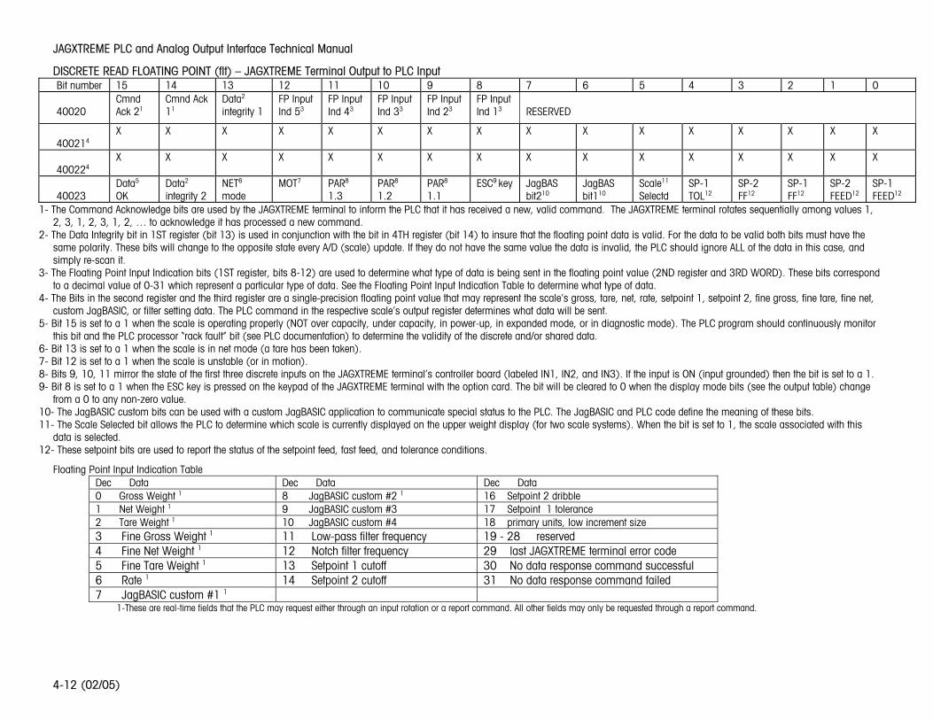
JAGXTREME PLC and Analog Output Interface Technical Manual
DISCRETE READ FLOATING POINT (flt) – JAGXTREME Terminal Output to PLC Input Bit number 15 14 13 12 11 10 9 8 7 6 5 4 3 2 1 0
40020
Cmnd Ack 21
Cmnd Ack 11
Data2 integrity 1
FP Input Ind 53
FP Input Ind 43
FP Input Ind 33
FP Input Ind 23
FP Input Ind 13
RESERVED
400214
X X X X X X X X X X X X X X X X
400224
X X X X X X X X X X X X X X X X
40023
Data5
OK Data2
integrity 2 NET6 mode
MOT7 PAR8 1.3
PAR8 1.2
PAR8 1.1
ESC9 key JagBASbit210
JagBAS bit110
Scale11
Selectd SP-1 TOL12
SP-2 FF12
SP-1 FF12
SP-2 FEED12
SP-1 FEED12
1- The Command Acknowledge bits are used by the JAGXTREME terminal to inform the PLC that it has received a new, valid command. The JAGXTREME terminal rotates sequentially among values 1, 2, 3, 1, 2, 3, 1, 2, … to acknowledge it has processed a new command.
2- The Data Integrity bit in 1ST register (bit 13) is used in conjunction with the bit in 4TH register (bit 14) to insure that the floating point data is valid. For the data to be valid both bits must have the same polarity. These bits will change to the opposite state every A/D (scale) update. If they do not have the same value the data is invalid, the PLC should ignore ALL of the data in this case, and simply re-scan it.
3- The Floating Point Input Indication bits (1ST register, bits 8-12) are used to determine what type of data is being sent in the floating point value (2ND register and 3RD WORD). These bits correspond to a decimal value of 0-31 which represent a particular type of data. See the Floating Point Input Indication Table to determine what type of data.
4- The Bits in the second register and the third register are a single-precision floating point value that may represent the scale’s gross, tare, net, rate, setpoint 1, setpoint 2, fine gross, fine tare, fine net, custom JagBASIC, or filter setting data. The PLC command in the respective scale’s output register determines what data will be sent.
5- Bit 15 is set to a 1 when the scale is operating properly (NOT over capacity, under capacity, in power-up, in expanded mode, or in diagnostic mode). The PLC program should continuously monitor this bit and the PLC processor “rack fault” bit (see PLC documentation) to determine the validity of the discrete and/or shared data.
6- Bit 13 is set to a 1 when the scale is in net mode (a tare has been taken). 7- Bit 12 is set to a 1 when the scale is unstable (or in motion). 8- Bits 9, 10, 11 mirror the state of the first three discrete inputs on the JAGXTREME terminal’s controller board (labeled IN1, IN2, and IN3). If the input is ON (input grounded) then the bit is set to a 1. 9- Bit 8 is set to a 1 when the ESC key is pressed on the keypad of the JAGXTREME terminal with the option card. The bit will be cleared to 0 when the display mode bits (see the output table) change
from a 0 to any non-zero value. 10- The JagBASIC custom bits can be used with a custom JagBASIC application to communicate special status to the PLC. The JagBASIC and PLC code define the meaning of these bits. 11- The Scale Selected bit allows the PLC to determine which scale is currently displayed on the upper weight display (for two scale systems). When the bit is set to 1, the scale associated with this
data is selected. 12- These setpoint bits are used to report the status of the setpoint feed, fast feed, and tolerance conditions.
Floating Point Input Indication Table Dec Data Dec Data Dec Data 0 Gross Weight 1 8 JagBASIC custom #2 1 16 Setpoint 2 dribble 1 Net Weight 1 9 JagBASIC custom #3 17 Setpoint 1 tolerance 2 Tare Weight 1 10 JagBASIC custom #4 18 primary units, low increment size 3 Fine Gross Weight 1 11 Low-pass filter frequency 19 - 28 reserved 4 Fine Net Weight 1 12 Notch filter frequency 29 last JAGXTREME terminal error code 5 Fine Tare Weight 1 13 Setpoint 1 cutoff 30 No data response command successful 6 Rate 1 14 Setpoint 2 cutoff 31 No data response command failed 7 JagBASIC custom #1 1
1-These are real-time fields that the PLC may request either through an input rotation or a report command. All other fields may only be requested through a report command.
(02/05) 4-12
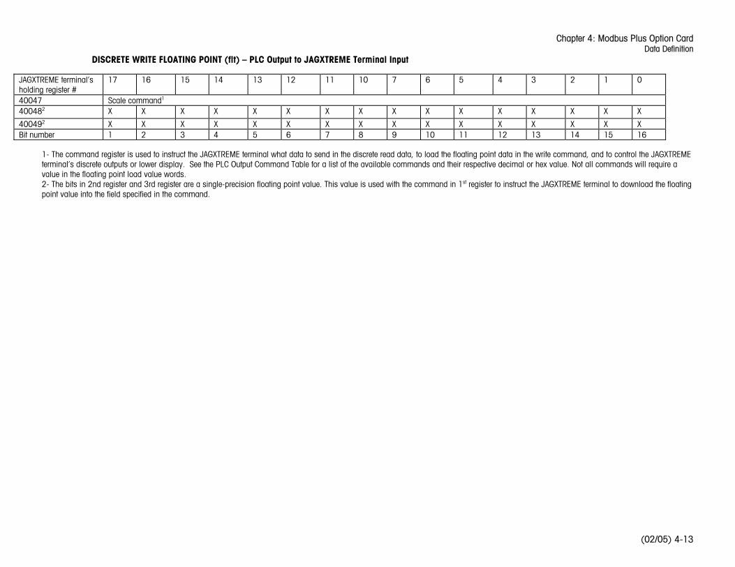
Chapter 4: Modbus Plus Option Card Data Definition
DISCRETE WRITE FLOATING POINT (flt) – PLC Output to JAGXTREME Terminal Input
JAGXTREME terminal’s holding register #
17 16 15 14 13 12 11 10 7 6 5 4 3 2 1 0
40047 Scale command1
400482 X X X X X X X X X X X X X X X X
400492 X X X X X X X X X X X X X X X XBit number 1 2 3 4 5 6 7 8 9 10 11 12 13 14 15 16
1- The command register is used to instruct the JAGXTREME terminal what data to send in the discrete read data, to load the floating point data in the write command, and to control the JAGXTREME terminal’s discrete outputs or lower display. See the PLC Output Command Table for a list of the available commands and their respective decimal or hex value. Not all commands will require a value in the floating point load value words. 2- The bits in 2nd register and 3rd register are a single-precision floating point value. This value is used with the command in 1st register to instruct the JAGXTREME terminal to download the floating point value into the field specified in the command.
(02/05) 4-13
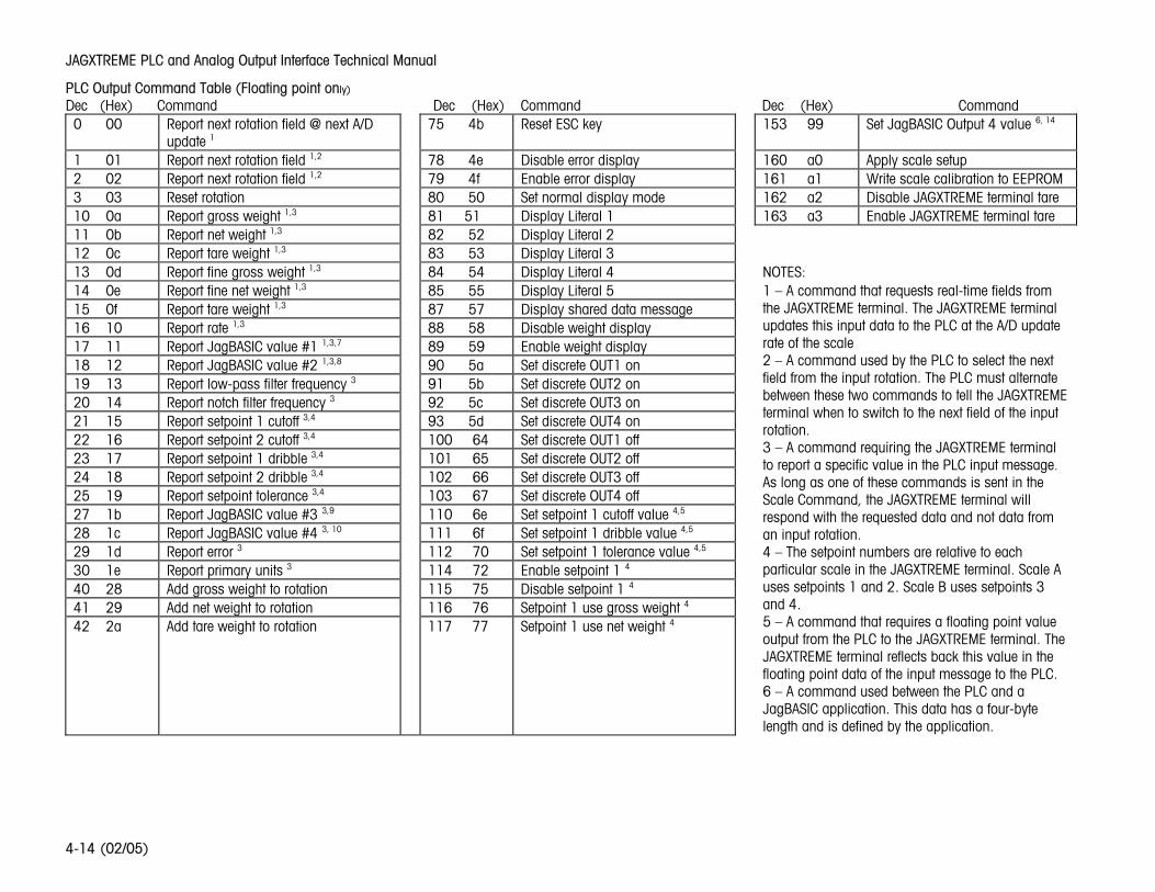
JAGXTREME PLC and Analog Output Interface Technical Manual
PLC Output Command Table (Floating point only)
Dec (Hex) Command Dec (Hex) Command Dec (Hex) Command 0 00 Report next rotation field @ next A/D
update 1 75 4b Reset ESC key 153 99 Set JagBASIC Output 4 value 6, 14
1 01 Report next rotation field 1,2 78 4e Disable error display 160 a0 Apply scale setup 2 02 Report next rotation field 1,2 79 4f Enable error display 161 a1 Write scale calibration to EEPROM 3 03 Reset rotation 80 50 Set normal display mode 162 a2 Disable JAGXTREME terminal tare 10 0a Report gross weight 1,3 81 51 Display Literal 1 163 a3 Enable JAGXTREME terminal tare 11 0b Report net weight 1,3 82 52 Display Literal 2 12 0c Report tare weight 1,3 83 53 Display Literal 3 13 0d Report fine gross weight 1,3 84 54 Display Literal 4 NOTES: 14 0e Report fine net weight 1,3 85 55 Display Literal 5 15 0f Report tare weight 1,3 87 57 Display shared data message 16 10 Report rate 1,3 88 58 Disable weight display 17 11 Report JagBASIC value #1 1,3,7 89 59 Enable weight display 18 12 Report JagBASIC value #2 1,3,8 90 5a Set discrete OUT1 on 19 13 Report low-pass filter frequency 3 91 5b Set discrete OUT2 on 20 14 Report notch filter frequency 3 92 5c Set discrete OUT3 on 21 15 Report setpoint 1 cutoff 3,4 93 5d Set discrete OUT4 on 22 16 Report setpoint 2 cutoff 3,4 100 64 Set discrete OUT1 off 23 17 Report setpoint 1 dribble 3,4 101 65 Set discrete OUT2 off 24 18 Report setpoint 2 dribble 3,4 102 66 Set discrete OUT3 off 25 19 Report setpoint tolerance 3,4 103 67 Set discrete OUT4 off 27 1b Report JagBASIC value #3 3,9 110 6e Set setpoint 1 cutoff value 4,5 28 1c Report JagBASIC value #4 3, 10 111 6f Set setpoint 1 dribble value 4,5 29 1d Report error 3 112 70 Set setpoint 1 tolerance value 4,5 30 1e Report primary units 3 114 72 Enable setpoint 1 4 40 28 Add gross weight to rotation 115 75 Disable setpoint 1 4 41 29 Add net weight to rotation 116 76 Setpoint 1 use gross weight 4 42 2a Add tare weight to rotation 117 77 Setpoint 1 use net weight 4
1 – A command that requests real-time fields from the JAGXTREME terminal. The JAGXTREME terminal updates this input data to the PLC at the A/D update rate of the scale 2 – A command used by the PLC to select the next field from the input rotation. The PLC must alternate between these two commands to tell the JAGXTREME terminal when to switch to the next field of the input rotation. 3 – A command requiring the JAGXTREME terminal to report a specific value in the PLC input message. As long as one of these commands is sent in the Scale Command, the JAGXTREME terminal will respond with the requested data and not data from an input rotation. 4 – The setpoint numbers are relative to each particular scale in the JAGXTREME terminal. Scale A uses setpoints 1 and 2. Scale B uses setpoints 3 and 4. 5 – A command that requires a floating point value output from the PLC to the JAGXTREME terminal. The JAGXTREME terminal reflects back this value in the floating point data of the input message to the PLC. 6 – A command used between the PLC and a JagBASIC application. This data has a four-byte length and is defined by the application.
(02/05) 4-14
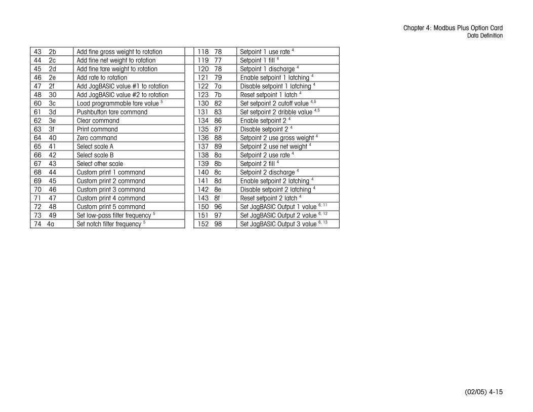
Chapter 4: Modbus Plus Option Card Data Definition
(02/05) 4-15
43 2b Add fine gross weight to rotation 118 78 Setpoint 1 use rate 4 44 2c Add fine net weight to rotation 119 77 Setpoint 1 fill 4 45 2d Add fine tare weight to rotation 120 78 Setpoint 1 discharge 4 46 2e Add rate to rotation 121 79 Enable setpoint 1 latching 4
47 2f Add JagBASIC value #1 to rotation 122 7a Disable setpoint 1 latching 4 48 30 Add JagBASIC value #2 to rotation 123 7b Reset setpoint 1 latch 4 60 3c Load programmable tare value 5 130 82 Set setpoint 2 cutoff value 4,5 61 3d Pushbutton tare command 131 83 Set setpoint 2 dribble value 4,5 62 3e Clear command 134 86 Enable setpoint 2 4 63 3f Print command 135 87 Disable setpoint 2 4 64 40 Zero command 136 88 Setpoint 2 use gross weight 4 65 41 Select scale A 137 89 Setpoint 2 use net weight 4 66 42 Select scale B 138 8a Setpoint 2 use rate 4 67 43 Select other scale 139 8b Setpoint 2 fill 4 68 44 Custom print 1 command 140 8c Setpoint 2 discharge 4 69 45 Custom print 2 command 141 8d Enable setpoint 2 latching 4 70 46 Custom print 3 command 142 8e Disable setpoint 2 latching 4 71 47 Custom print 4 command 143 8f Reset setpoint 2 latch 4 72 48 Custom print 5 command 150 96 Set JagBASIC Output 1 value 6, 11 73 49 Set low-pass filter frequency 5 151 97 Set JagBASIC Output 2 value 6, 12 74 4a Set notch filter frequency 5 152 98 Set JagBASIC Output 3 value 6, 13
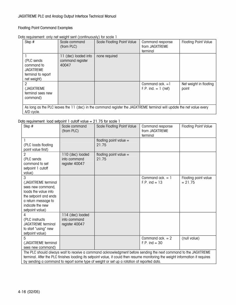
JAGXTREME PLC and Analog Output Interface Technical Manual
Floating Point Command Examples Data requirement: only net weight sent (continuously) for scale 1
Step # Scale command (from PLC)
Scale Floating Point Value Command response from JAGXTREME terminal
Floating Point Value
1 (PLC sends command to JAGXTREME terminal to report net weight)
11 (dec) loaded into command register 40047
none required
2 (JAGXTREME terminal sees new command)
Command ack. =1 F.P. ind. = 1 (net)
Net weight in floating point
As long as the PLC leaves the 11 (dec) in the command register the JAGXTREME terminal will update the net value every A/D cycle.
Data requirement: load setpoint 1 cutoff value = 21.75 for scale 1
Step # Scale command (from PLC)
Scale Floating Point Value Command response from JAGXTREME terminal
Floating Point Value
1 (PLC loads floating point value first)
floating point value = 21.75
2 (PLC sends command to set setpoint 1 cutoff value)
110 (dec) loaded into command register 40047
floating point value = 21.75
3 (JAGXTREME terminal sees new command, loads the value into the setpoint and ends a return message to indicate the new setpoint value)
Command ack. = 1 F.P. ind = 13
Floating point value = 21.75
4 (PLC instructs JAGXTREME terminal to start “using” new setpoint value)
114 (dec) loaded into command register 40047
5 (JAGXTREME terminal sees new command)
Command ack. = 2 F.P. ind = 30
(null value)
The PLC should always wait to receive a command acknowledgment before sending the next command to the JAGXTREME terminal. After the PLC finishes loading its setpoint value, it could then resume monitoring the weight information it requires by sending a command to report some type of weight or set up a rotation of reported data.
(02/05) 4-16
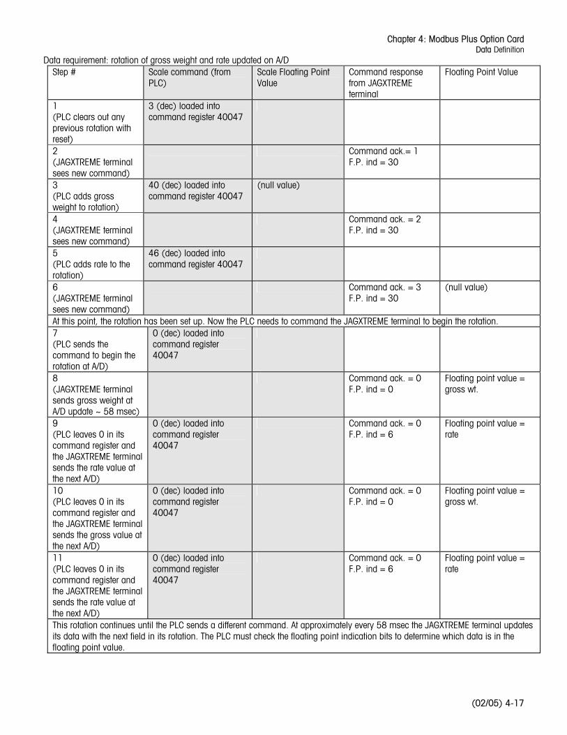
Chapter 4: Modbus Plus Option Card Data Definition
Data requirement: rotation of gross weight and rate updated on A/D Step # Scale command (from
PLC) Scale Floating Point Value
Command response from JAGXTREME terminal
Floating Point Value
1 (PLC clears out any previous rotation with reset)
3 (dec) loaded into command register 40047
2 (JAGXTREME terminal sees new command)
Command ack.= 1 F.P. ind = 30
3 (PLC adds gross weight to rotation)
40 (dec) loaded into command register 40047
(null value)
4 (JAGXTREME terminal sees new command)
Command ack. = 2 F.P. ind = 30
5 (PLC adds rate to the rotation)
46 (dec) loaded into command register 40047
6 (JAGXTREME terminal sees new command)
Command ack. = 3 F.P. ind = 30
(null value)
At this point, the rotation has been set up. Now the PLC needs to command the JAGXTREME terminal to begin the rotation. 7 (PLC sends the command to begin the rotation at A/D)
0 (dec) loaded into command register 40047
8 (JAGXTREME terminal sends gross weight at A/D update ~ 58 msec)
Command ack. = 0 F.P. ind = 0
Floating point value = gross wt.
9 (PLC leaves 0 in its command register and the JAGXTREME terminal sends the rate value at the next A/D)
0 (dec) loaded into command register 40047
Command ack. = 0 F.P. ind = 6
Floating point value = rate
10 (PLC leaves 0 in its command register and the JAGXTREME terminal sends the gross value at the next A/D)
0 (dec) loaded into command register 40047
Command ack. = 0 F.P. ind = 0
Floating point value = gross wt.
11 (PLC leaves 0 in its command register and the JAGXTREME terminal sends the rate value at the next A/D)
0 (dec) loaded into command register 40047
Command ack. = 0 F.P. ind = 6
Floating point value = rate
This rotation continues until the PLC sends a different command. At approximately every 58 msec the JAGXTREME terminal updates its data with the next field in its rotation. The PLC must check the floating point indication bits to determine which data is in the floating point value.
(02/05) 4-17
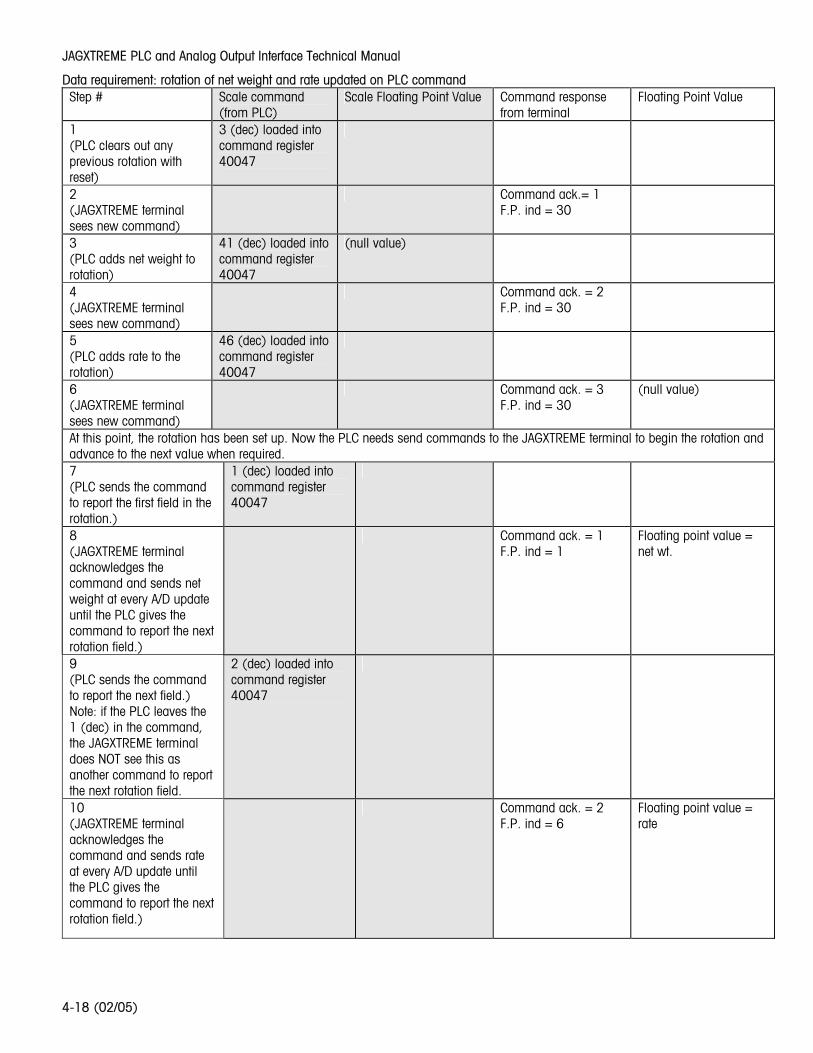
JAGXTREME PLC and Analog Output Interface Technical Manual
Data requirement: rotation of net weight and rate updated on PLC command Step # Scale command
(from PLC) Scale Floating Point Value Command response
from terminal Floating Point Value
1 (PLC clears out any previous rotation with reset)
3 (dec) loaded into command register 40047
2 (JAGXTREME terminal sees new command)
Command ack.= 1 F.P. ind = 30
3 (PLC adds net weight to rotation)
41 (dec) loaded into command register 40047
(null value)
4 (JAGXTREME terminal sees new command)
Command ack. = 2 F.P. ind = 30
5 (PLC adds rate to the rotation)
46 (dec) loaded into command register 40047
6 (JAGXTREME terminal sees new command)
Command ack. = 3 F.P. ind = 30
(null value)
At this point, the rotation has been set up. Now the PLC needs send commands to the JAGXTREME terminal to begin the rotation and advance to the next value when required. 7 (PLC sends the command to report the first field in the rotation.)
1 (dec) loaded into command register 40047
8 (JAGXTREME terminal acknowledges the command and sends net weight at every A/D update until the PLC gives the command to report the next rotation field.)
Command ack. = 1 F.P. ind = 1
Floating point value = net wt.
9 (PLC sends the command to report the next field.) Note: if the PLC leaves the 1 (dec) in the command, the JAGXTREME terminal does NOT see this as another command to report the next rotation field.
2 (dec) loaded into command register 40047
10 (JAGXTREME terminal acknowledges the command and sends rate at every A/D update until the PLC gives the command to report the next rotation field.)
Command ack. = 2 F.P. ind = 6
Floating point value = rate
(02/05) 4-18
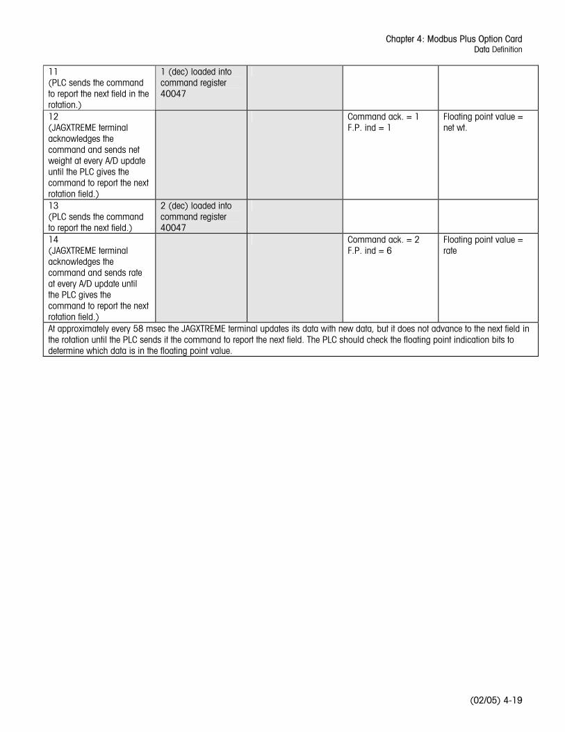
Chapter 4: Modbus Plus Option Card Data Definition
11 (PLC sends the command to report the next field in the rotation.)
1 (dec) loaded into command register 40047
12 (JAGXTREME terminal acknowledges the command and sends net weight at every A/D update until the PLC gives the command to report the next rotation field.)
Command ack. = 1 F.P. ind = 1
Floating point value = net wt.
13 (PLC sends the command to report the next field.)
2 (dec) loaded into command register 40047
14 (JAGXTREME terminal acknowledges the command and sends rate at every A/D update until the PLC gives the command to report the next rotation field.)
Command ack. = 2 F.P. ind = 6
Floating point value = rate
At approximately every 58 msec the JAGXTREME terminal updates its data with new data, but it does not advance to the next field in the rotation until the PLC sends it the command to report the next field. The PLC should check the floating point indication bits to determine which data is in the floating point value.
(02/05) 4-19
JAGXTREME PLC and Analog Output Interface Technical Manual
Shared Data
Operational Overview Modbus Plus PLCs can access the JAGXTREME terminal’s Shared Data. Since the Modbus Plus communications supports larger size messages, there is not a need for two separate modes of communication. Modbus Plus PLCs can read JAGXTREME terminal Shared Data variables, write new values to JAGXTREME terminal Shared Data variables, and write operator messages on the terminal’s lower display. For Modbus Plus, the PLC output data had additional fields for accessing Shared Data. The PLC must specify the Shared Data command and variable name in the PLC output message. If the command is a write command, then the PLC output message must also contain the write field value. The maximum length of this value is 20 bytes. When the Shared Data command is a read command, the PLC input message will have a read field containing the data from the Shared Data variable specified in the output message. The maximum length of the data reported in the read field is 20 bytes. The Shared Data variables are self-typing. The terminal determines the type of any valid data field in the message from the variable’s name and definition in Shared Data. The terminal will not allow string data to be written in a floating point variable or visa versa.
Shared Data Input The input information for the shared data consists of two sections: the shared data status and the shared data read field value (if requested by the shared data output command). The shared data status information is a register that contains an integer value. This integer value represents one of the following status values:
0 Null status
1 Command completed successfully
2 Invalid shared data name
3 Invalid shared data command Note: Refer to the Shared Data Reference Guide for a complete listing of Shared Data Fields.
4 Cannot write because field is write-protected (legal for trade)
5 Cannot access remote JAGXTREME terminal
The shared data read field value contains the value of the shared data variable specified in the shared data output (from the PLC to the terminal). It is only present when the command from the shared data output requests read shared data. This value is self-typing; for example, it could be a floating point number or a string variable. The length is determined by the variable selected but will exceed 20 bytes. See the tables following the Shared Data Output section for a list of possible variables and their contents.
Shared Data Output The output information for the shared data consists of four sections: the shared data command, the shared data name, the shared data variable name, and the shared data write value (if required by the shared data output command). The shared data command information is a register that contains an integer value. This integer value represents one of the following status values:
0 Null command
1 Read shared data
2 Write shared data
3 Write to JAGXTREME lower display
(02/05) 4-20
Chapter 4: Modbus Plus Option Card Data Definition
The JAGXTREME terminal processes a shared data command “on demand” by the PLC. When a new value is placed in the shared data command register, the terminal will perform the command issued. The terminal does not provide “real time” information to the PLC; it supplies a “snapshot’ of the data not an automatic update of new values of the same shared data command. Instead, the PLC must request the information again by setting a new value in the shared data command register. To do successive reads, for example, the PLC must alternate between a “null” command and a “read” command in the shared data command register. For the most efficient processing, the PLC should set up the terminal name, the variable name, and the write value (if any) while it is setting the “null” command. Once that is completed, the PLC can then set the shared data command to “read” or “write”.
Before sending a command to write to the terminal’s lower display, the PLC must issue a display mode command in the scale command registers (command 57 for floating point data; 2nd output register bits 9-11 = on for other data formats) to enable the terminal to accept commands for its display.
Floating Point and String Data Field Codes The following charts describe the floating point and string data fields that the JAGXTREME terminal can access. String data fields are serial ASCII character strings. Each table contains the following information:
Field Code is the ASCII field that must be loaded into the PLC write buffer. It identifies the data that is written to the JAGXTREME terminal or returned by the terminal to the PLC read buffer. The field code is left justified and must be expanded to six bytes by adding a trailing space. If the field code contains an "n", it should be replaced by the scale number (1 or 2 for scale A or B) or the setpoint number (1-8).
Description is a description of the field.
Read/Write indicates whether the PLC can read and/or write to the field.
Length is the number of bytes (length) of the field. All floating point values are 4 bytes (2 words) long. Strings are the length specified.
(02/05) 4-21
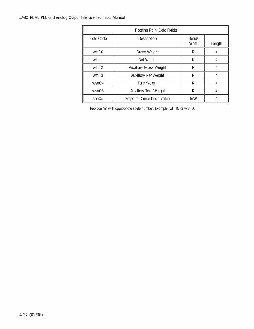
JAGXTREME PLC and Analog Output Interface Technical Manual
Floating Point Data Fields
Field Code Description Read/ Write
Length
wtn10 Gross Weight R 4
wtn11 Net Weight R 4
wtn12 Auxiliary Gross Weight R 4
wtn13 Auxiliary Net Weight R 4
wsn04 Tare Weight R 4
wsn05 Auxiliary Tare Weight R 4
spn05 Setpoint Coincidence Value R/W 4
Replace “n” with appropriate scale number. Example: wt110 or wt210.
(02/05) 4-22
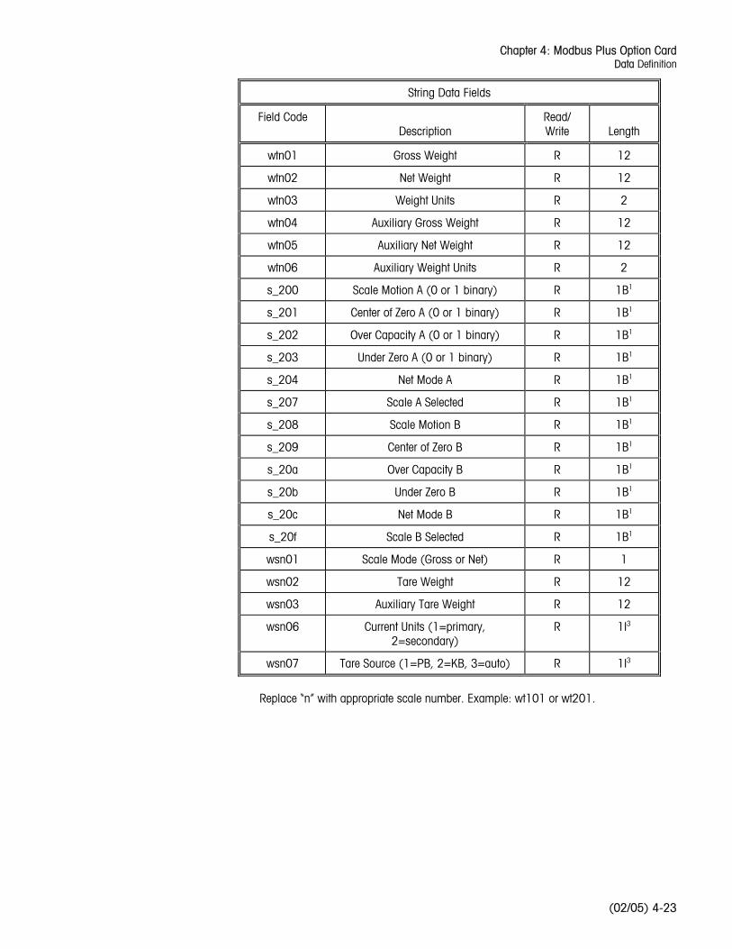
Chapter 4: Modbus Plus Option Card Data Definition
String Data Fields
Field Code Description
Read/ Write
Length
wtn01 Gross Weight R 12
wtn02 Net Weight R 12
wtn03 Weight Units R 2
wtn04 Auxiliary Gross Weight R 12
wtn05 Auxiliary Net Weight R 12
wtn06 Auxiliary Weight Units R 2
s_200 Scale Motion A (0 or 1 binary) R 1B1
s_201 Center of Zero A (0 or 1 binary) R 1B1
s_202 Over Capacity A (0 or 1 binary) R 1B1
s_203 Under Zero A (0 or 1 binary) R 1B1
s_204 Net Mode A R 1B1
s_207 Scale A Selected R 1B1
s_208 Scale Motion B R 1B1
s_209 Center of Zero B R 1B1
s_20a Over Capacity B R 1B1
s_20b Under Zero B R 1B1
s_20c Net Mode B R 1B1
s_20f Scale B Selected R 1B1
wsn01 Scale Mode (Gross or Net) R 1
wsn02 Tare Weight R 12
wsn03 Auxiliary Tare Weight R 12
wsn06 Current Units (1=primary, 2=secondary)
R 1I3
wsn07 Tare Source (1=PB, 2=KB, 3=auto) R 1I3
Replace “n” with appropriate scale number. Example: wt101 or wt201.
(02/05) 4-23
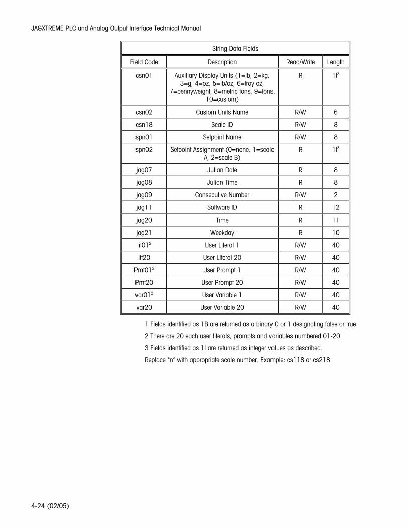
JAGXTREME PLC and Analog Output Interface Technical Manual
String Data Fields
Field Code Description Read/Write Length
csn01 Auxiliary Display Units (1=lb, 2=kg, 3=g, 4=oz, 5=lb/oz, 6=troy oz,
7=pennyweight, 8=metric tons, 9=tons, 10=custom)
R 1I3
csn02 Custom Units Name R/W 6
csn18 Scale ID R/W 8
spn01 Setpoint Name R/W 8
spn02 Setpoint Assignment (0=none, 1=scale A, 2=scale B)
R 1I3
jag07 Julian Date R 8
jag08 Julian Time R 8
jag09 Consecutive Number R/W 2
jag11 Software ID R 12
jag20 Time R 11
jag21 Weekday R 10
lit012 User Literal 1 R/W 40
lit20 User Literal 20 R/W 40
Pmt012 User Prompt 1 R/W 40
Pmt20 User Prompt 20 R/W 40
var012 User Variable 1 R/W 40
var20 User Variable 20 R/W 40
1 Fields identified as 1B are returned as a binary 0 or 1 designating false or true.
2 There are 20 each user literals, prompts and variables numbered 01-20.
3 Fields identified as 1I are returned as integer values as described.
Replace “n” with appropriate scale number. Example: cs118 or cs218.
(02/05) 4-24
Chapter 4: Modbus Plus Option Card Hardware Setup
Global Data The JAGXTREME terminal supports Modbus Plus Global Data as an option. The terminal writes to Global Data, but never reads Global Data. Global Data from one Modbus Plus node is continuously available to all other nodes on the network. Use of Global Data can make programming the PLC simpler since, with this option, the PLC need not continuously issue commands to read the terminal registers. The PLC must still issue MSTR commands to send commands to the terminal.
The user selects the Global Data option in the setup menus. When the user selects the integer data format, the terminal duplicates the integer “terminal-to-PLC” data transfer registers into the global data. When the user selects the floating point data format, the terminal duplicates the floating point “terminal-to-PLC” data transfer registers into the global data.
Controlling the Discrete I/O Using a PLC Interface
The JAGXTREME terminal provides the ability to directly control its discrete outputs and read its discrete inputs via the (digital) PLC interface options. System integrators should be aware that the terminal discrete I/O updates are synchronized with the A/D rate and not with the PLC I/O scan rate. This may cause a noticeable delay in reading inputs or updating outputs as observed from the PLC to real world signals.
Hardware Setup
Wiring The Modbus Plus Option has two possible connections: a D9 connector or a 4-position removable terminal strip to connect to the Modbus Plus network interface. Most installations will use the D9 connector. The terminal strip should only be used in applications where the adapter harness (PN 0900-0320-000), which provides an external D9 connection for general purpose and harsh environment models, is required. Cable distance, type, and termination are specified by Modbus Plus. Female DE-9
1 Shield (to Modicon D9 conn. terminal 2)
2 White (to Modicon D9 conn. terminal 1)
3 Black (to Modicon D9 conn. terminal 3)
4 N.C.
5 N.C.
6 N.C.
7 N.C.
8 N.C.
9 N.C.
(02/05) 4-25
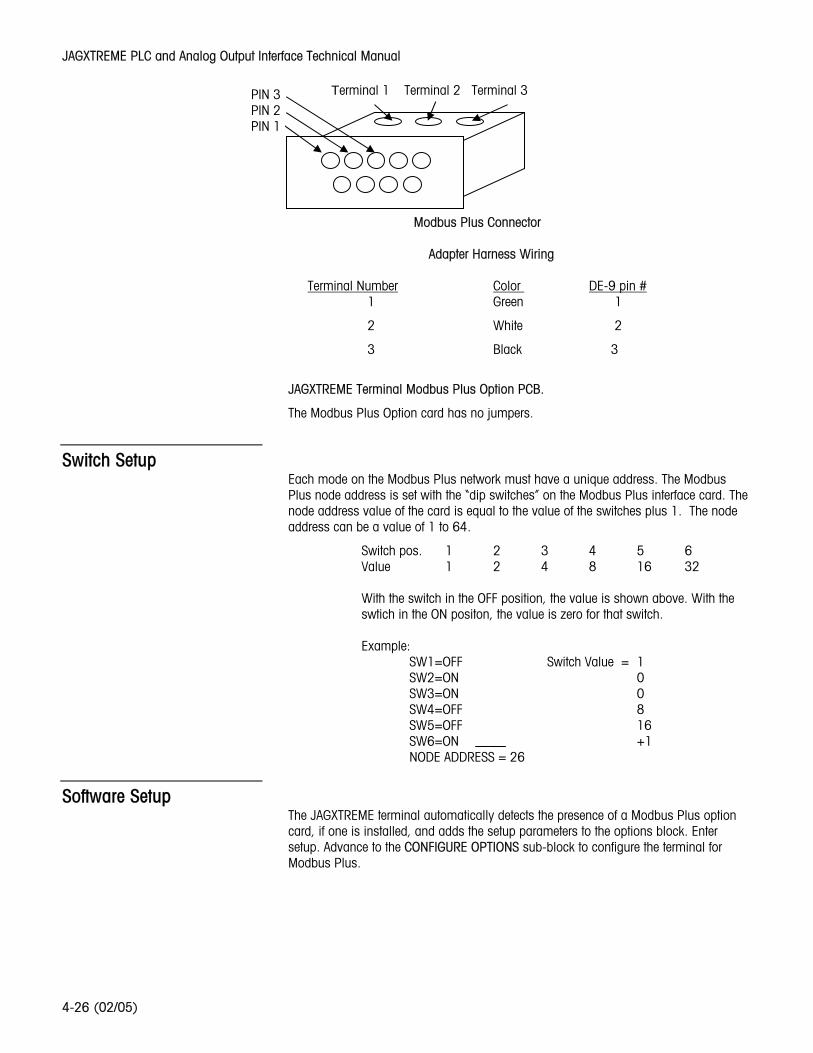
JAGXTREME PLC and Analog Output Interface Technical Manual
Terminal 1 Terminal 2 Terminal 3
PIN 3 PIN 2 PIN 1
Modbus Plus Connector Adapter Harness Wiring Terminal Number Color DE-9 pin #
1 Green 1
2 White 2
3 Black 3
JAGXTREME Terminal Modbus Plus Option PCB.
The Modbus Plus Option card has no jumpers.
Switch Setup Each mode on the Modbus Plus network must have a unique address. The Modbus Plus node address is set with the “dip switches” on the Modbus Plus interface card. The node address value of the card is equal to the value of the switches plus 1. The node address can be a value of 1 to 64.
Switch pos. 1 2 3 4 5 6 Value 1 2 4 8 16 32 With the switch in the OFF position, the value is shown above. With the swtich in the ON positon, the value is zero for that switch. Example:
SW1=OFF Switch Value = 1 SW2=ON 0 SW3=ON 0 SW4=OFF 8 SW5=OFF 16 SW6=ON +1 NODE ADDRESS = 26
Software Setup The JAGXTREME terminal automatically detects the presence of a Modbus Plus option card, if one is installed, and adds the setup parameters to the options block. Enter setup. Advance to the CONFIGURE OPTIONS sub-block to configure the terminal for Modbus Plus.
(02/05) 4-26
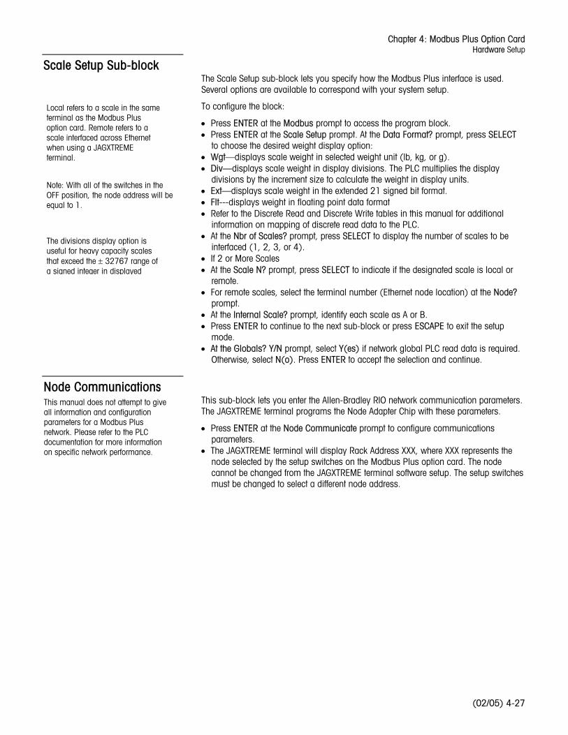
Chapter 4: Modbus Plus Option Card Hardware Setup
Scale Setup Sub-block The Scale Setup sub-block lets you specify how the Modbus Plus interface is used. Several options are available to correspond with your system setup.
To configure the block: Local refers to a scale in the same terminal as the Modbus Plus option card. Remote refers to a scale interfaced across Ethernet when using a JAGXTREME terminal.
• Press ENTER at the Modbus prompt to access the program block. • Press ENTER at the Scale Setup prompt. At the Data Format? prompt, press SELECT
to choose the desired weight display option: • Wgt—displays scale weight in selected weight unit (lb, kg, or g). • Div—displays scale weight in display divisions. The PLC multiplies the display
divisions by the increment size to calculate the weight in display units. Note: With all of the switches in the OFF position, the node address will be equal to 1.
• Ext—displays scale weight in the extended 21 signed bit format. • Flt---displays weight in floating point data format • Refer to the Discrete Read and Discrete Write tables in this manual for additional
information on mapping of discrete read data to the PLC. • At the Nbr of Scales? prompt, press SELECT to display the number of scales to be
interfaced (1, 2, 3, or 4). The divisions display option is useful for heavy capacity scales that exceed the ± 32767 range of a signed integer in displayed
• If 2 or More Scales • At the Scale N? prompt, press SELECT to indicate if the designated scale is local or
remote. • For remote scales, select the terminal number (Ethernet node location) at the Node?
prompt. • At the Internal Scale? prompt, identify each scale as A or B. • Press ENTER to continue to the next sub-block or press ESCAPE to exit the setup
mode. • At the Globals? Y/N prompt, select Y(es) if network global PLC read data is required.
Otherwise, select N(o). Press ENTER to accept the selection and continue.
Node Communications This sub-block lets you enter the Allen-Bradley RIO network communication parameters. The JAGXTREME terminal programs the Node Adapter Chip with these parameters.
• Press ENTER at the Node Communicate prompt to configure communications parameters.
• The JAGXTREME terminal will display Rack Address XXX, where XXX represents the node selected by the setup switches on the Modbus Plus option card. The node cannot be changed from the JAGXTREME terminal software setup. The setup switches must be changed to select a different node address.
This manual does not attempt to give all information and configuration parameters for a Modbus Plus network. Please refer to the PLC documentation for more information on specific network performance.
(02/05) 4-27
JAGXTREME PLC and Analog Output Interface Technical Manual
Reset to Factory Sub-block If desired, you can reset the parameters for this program block to the default values. Reset to Factory returns all
parameters for this block to their original settings. You cannot reset a single value or specify only a few of the sub-block values.
To reset the program block parameters:
• Press ENTER at the Reset to Factory prompt. • At the Are You Sure? prompt, press SELECT to highlight Y(es) to confirm and reset the
values to factory defaults, or select N(o) if you do not wish to reset the values. • Press ESCAPE to exit the sub-block. • Press SELECT to continue to another program block if desired.
Troubleshooting
Modbus Plus Option PCB Status Lights There is a green diagnostic LED on the JAGXTREME terminal Modbus Plus option card, which is viewable through a small hole in the interface mounting bracket at the rear of the terminal. The repetitive flashing patterns have the following meanings.
Flash every 160 milliseconds. The terminal node is working normally in that it is successfully receiving and passing the token. Every node on the link should be flashing this same pattern.
Flash every one second. The terminal node is in an off-line state where it must monitor the link for five seconds. During this period, it hears all active nodes on the network and is building the active station table.
Two flashes, off for two seconds. The terminal node is permanently in an idle, never-getting-token state. It is hearing the other nodes but is never getting the token itself. This JAGXTREME terminal node may have a bad transmitter.
Three flashes, off for 1.7 seconds. This terminal node is not hearing any other nodes so it is periodically claiming and winning the token, and then finding no other node to send it to. It could be that this is the only node on the link, or that there are other nodes and this has node a bad receiver or bad network connection. The latter situation could be disruptive to the entire network.
Four flashes, off for 1.4 seconds. This terminal node has heard a valid packet that was a duplicate-node-address sent from another node on the network. The node is now in an off-line state where it will remain passively monitoring the link, until it has not heard the duplicate node for 5 seconds.
(02/05) 4-28
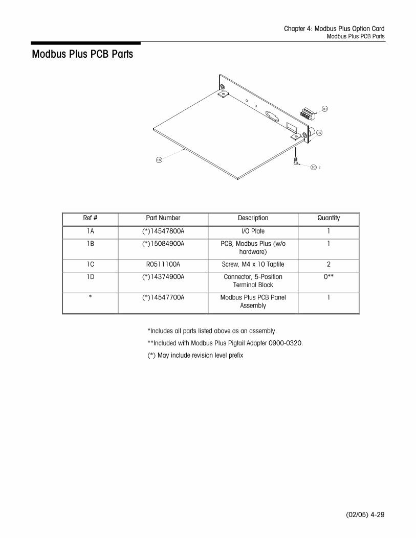
Chapter 4: Modbus Plus Option Card Modbus Plus PCB Parts
Modbus Plus PCB Parts
1A
1C 2
1B
1D
Ref # Part Number Description Quantity
1A (*)14547800A I/O Plate 1
1B (*)15084900A PCB, Modbus Plus (w/o hardware)
1
1C R0511100A Screw, M4 x 10 Taptite 2
1D (*)14374900A Connector, 5-Position Terminal Block
0**
* (*)14547700A Modbus Plus PCB Panel Assembly
1
*Includes all parts listed above as an assembly.
**Included with Modbus Plus Pigtail Adapter 0900-0320.
(*) May include revision level prefix
(02/05) 4-29
JAGXTREME PLC and Analog Output Interface Technical Manual
Modicon 984-385E Setup Example
A Modbus Plus network cable connects the JAGXTREME terminal Modbus Plus Interface to the Modbus Plus port on the 984-385E Programmable Controller Module. Set the node address for the 984-385E PLC using the DIP switches on the bottom of the Programmable Controller Module.
Refer to the Modicon Modbus Plus Network Planning and Installation Guide for information on network cabling, terminating connectors, and in-line connectors needed to build a network cable.
The Modbus Plus indicator on the 984-385E front panel indicates a good connection to the terminal when it is constantly flashing green. There is also a green diagnostic LED on the Modbus Plus Option card. The terminal has made a good network connection when it constantly flashes the green LED every 160 milliseconds.
Modsoft programming software running on a PC controls the Modicon 984-385E PLC. A serial cable connects a serial port on the PC to the Modbus port on the PLC. The Modsoft Programmer User Manual describes how to use Modsoft. Use 2.32 or a later version of the Modsoft software. Perform the following steps from Modsoft to read and write to a terminal on the Modbus Plus network from a Modicon 984-385 PLC:
• With Modsoft running on a PC, go to the Configuration Overview screen and select the 984-385E PLC.
• Switch to the Configuration Overview - Ports menu, and change the Modbus port to Bridge mode. This allows commands issued from Modsoft to be transferred to the Modbus Plus network.
• From the Modsoft main menu, go “on-line” to the 984-385E PLC from Modsoft. • Once a successful connection has been made, use the MSTR instruction to access
the terminal. The Modicon Ladder Logic Block Library User Guide gives detailed information about the MSTR instruction.
(02/05) 4-30
Chapter 4: Modbus Plus Option Card Modicon 984-385E Setup Example
MSTR Instruction Example to Read Integer Registers This example shows using the MSTR instruction to read the integer status and weight registers in the terminal. In this example, the terminal is at node 2 in the dip switches on the Modbus Plus interface card. The user must configure the terminal to run in integer mode using the <Config Options><Modbus Plus><Scale Setup><Data Format?> menus. This MSTR reads the holding registers for four scales in integer mode.
Control Block
PLC Register Content
41001 0002 Dec Read command
41002 xxxx Hex Error status
41003 0008 Dec Number of registers to be read
41004 0001 Dec Starting address of integer weight/status registers in the JAGXTREME terminal. (1 = 40001).
41005 0002 Hex Routing path. JAGXTREME terminal address = node 2.
41006 0001 Dec Data slave routing path.
41007 0000 Dec Additional routing register
41008 0000 Dec Additional routing register
41009 0000 Dec Additional routing register
Data Area
PLC Register
41100 The PLC stores registers read from the JAGXTREME terminal registers 40001-40007 starting here.
Length
0008 This integer value defines the length of the Data Area.
(02/05) 4-31
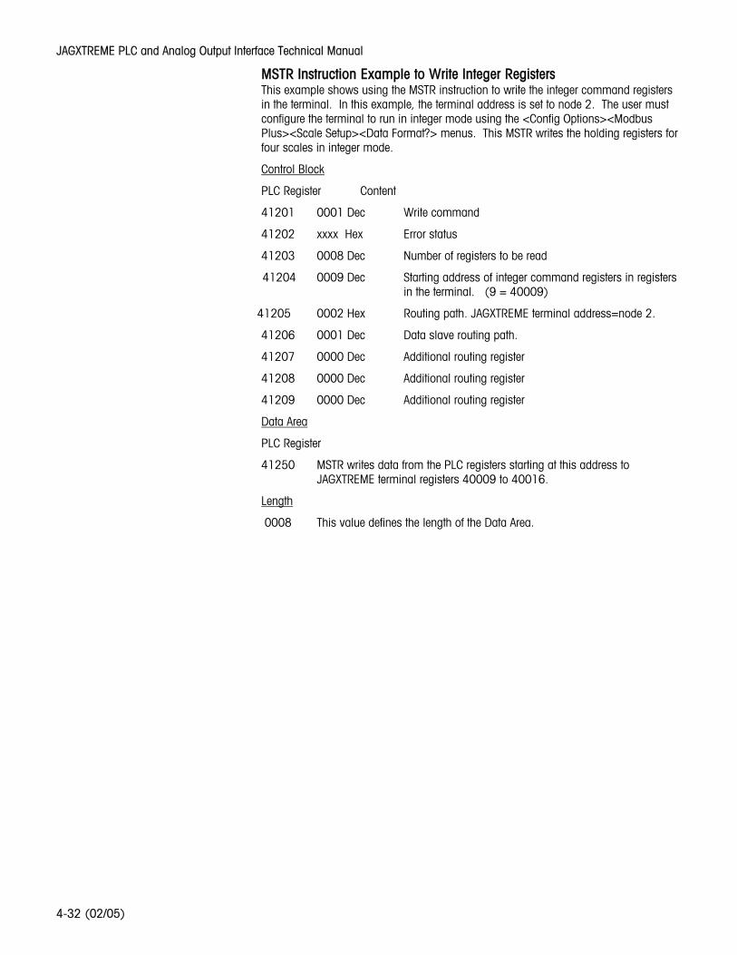
JAGXTREME PLC and Analog Output Interface Technical Manual
MSTR Instruction Example to Write Integer Registers This example shows using the MSTR instruction to write the integer command registers in the terminal. In this example, the terminal address is set to node 2. The user must configure the terminal to run in integer mode using the <Config Options><Modbus Plus><Scale Setup><Data Format?> menus. This MSTR writes the holding registers for four scales in integer mode.
Control Block
PLC Register Content
41201 0001 Dec Write command
41202 xxxx Hex Error status
41203 0008 Dec Number of registers to be read
41204 0009 Dec Starting address of integer command registers in registers in the terminal. (9 = 40009)
41205 0002 Hex Routing path. JAGXTREME terminal address=node 2.
41206 0001 Dec Data slave routing path.
41207 0000 Dec Additional routing register
41208 0000 Dec Additional routing register
41209 0000 Dec Additional routing register
Data Area
PLC Register
41250 MSTR writes data from the PLC registers starting at this address to JAGXTREME terminal registers 40009 to 40016.
Length
0008 This value defines the length of the Data Area.
(02/05) 4-32
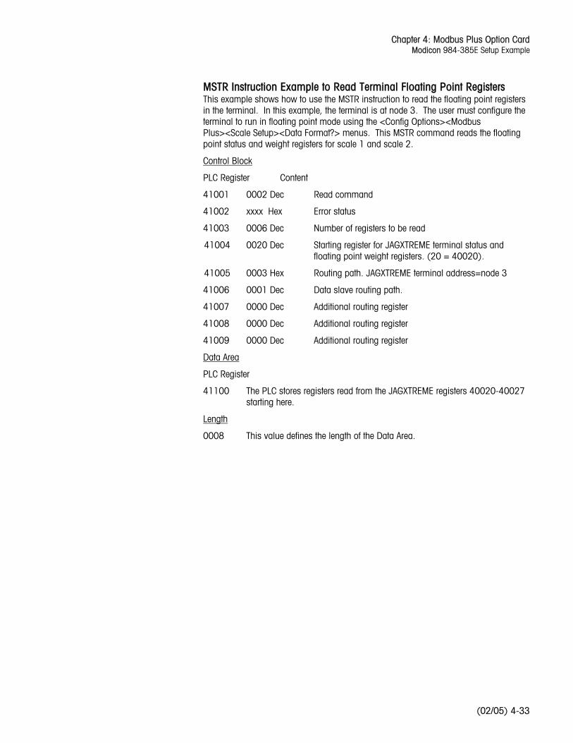
Chapter 4: Modbus Plus Option Card Modicon 984-385E Setup Example
MSTR Instruction Example to Read Terminal Floating Point Registers This example shows how to use the MSTR instruction to read the floating point registers in the terminal. In this example, the terminal is at node 3. The user must configure the terminal to run in floating point mode using the <Config Options><Modbus Plus><Scale Setup><Data Format?> menus. This MSTR command reads the floating point status and weight registers for scale 1 and scale 2.
Control Block
PLC Register Content
41001 0002 Dec Read command
41002 xxxx Hex Error status
41003 0006 Dec Number of registers to be read
41004 0020 Dec Starting register for JAGXTREME terminal status and floating point weight registers. (20 = 40020).
41005 0003 Hex Routing path. JAGXTREME terminal address=node 3
41006 0001 Dec Data slave routing path.
41007 0000 Dec Additional routing register
41008 0000 Dec Additional routing register
41009 0000 Dec Additional routing register
Data Area
PLC Register
41100 The PLC stores registers read from the JAGXTREME registers 40020-40027 starting here.
Length
0008 This value defines the length of the Data Area.
(02/05) 4-33
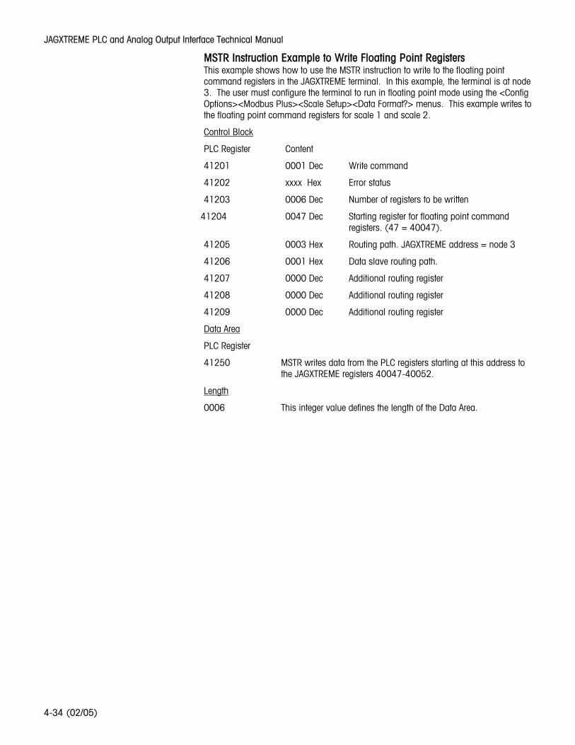
JAGXTREME PLC and Analog Output Interface Technical Manual
MSTR Instruction Example to Write Floating Point Registers This example shows how to use the MSTR instruction to write to the floating point command registers in the JAGXTREME terminal. In this example, the terminal is at node 3. The user must configure the terminal to run in floating point mode using the <Config Options><Modbus Plus><Scale Setup><Data Format?> menus. This example writes to the floating point command registers for scale 1 and scale 2.
Control Block
PLC Register Content
41201 0001 Dec Write command
41202 xxxx Hex Error status
41203 0006 Dec Number of registers to be written
41204 0047 Dec Starting register for floating point command registers. (47 = 40047).
41205 0003 Hex Routing path. JAGXTREME address = node 3
41206 0001 Hex Data slave routing path.
41207 0000 Dec Additional routing register
41208 0000 Dec Additional routing register
41209 0000 Dec Additional routing register
Data Area
PLC Register
41250 MSTR writes data from the PLC registers starting at this address to the JAGXTREME registers 40047-40052.
Length
0006 This integer value defines the length of the Data Area.
(02/05) 4-34
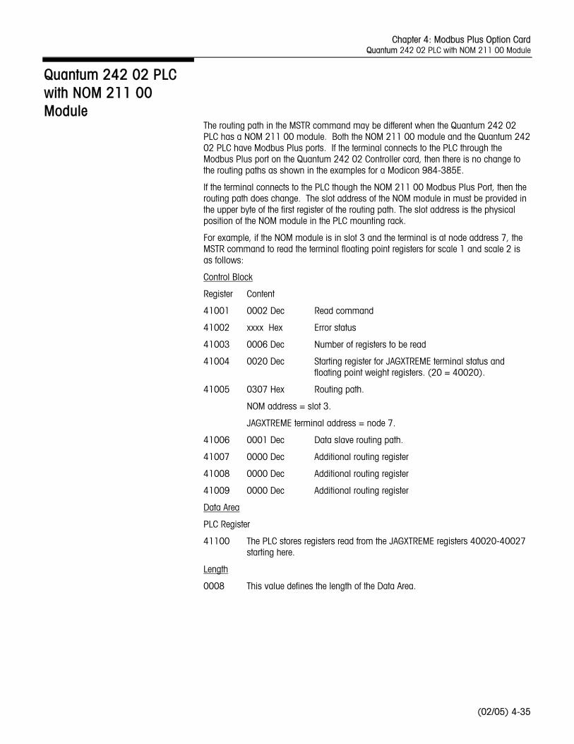
Chapter 4: Modbus Plus Option Card Quantum 242 02 PLC with NOM 211 00 Module
Quantum 242 02 PLC with NOM 211 00 Module
The routing path in the MSTR command may be different when the Quantum 242 02 PLC has a NOM 211 00 module. Both the NOM 211 00 module and the Quantum 242 02 PLC have Modbus Plus ports. If the terminal connects to the PLC through the Modbus Plus port on the Quantum 242 02 Controller card, then there is no change to the routing paths as shown in the examples for a Modicon 984-385E.
If the terminal connects to the PLC though the NOM 211 00 Modbus Plus Port, then the routing path does change. The slot address of the NOM module in must be provided in the upper byte of the first register of the routing path. The slot address is the physical position of the NOM module in the PLC mounting rack.
For example, if the NOM module is in slot 3 and the terminal is at node address 7, the MSTR command to read the terminal floating point registers for scale 1 and scale 2 is as follows:
Control Block
Register Content
41001 0002 Dec Read command
41002 xxxx Hex Error status
41003 0006 Dec Number of registers to be read
41004 0020 Dec Starting register for JAGXTREME terminal status and floating point weight registers. (20 = 40020).
41005 0307 Hex Routing path.
NOM address = slot 3.
JAGXTREME terminal address = node 7.
41006 0001 Dec Data slave routing path.
41007 0000 Dec Additional routing register
41008 0000 Dec Additional routing register
41009 0000 Dec Additional routing register
Data Area
PLC Register
41100 The PLC stores registers read from the JAGXTREME registers 40020-40027 starting here.
Length
0008 This value defines the length of the Data Area.
(02/05) 4-35

JAGXTREME PLC and Analog Output Interface Technical Manual
For your notes
(02/05) 4-36
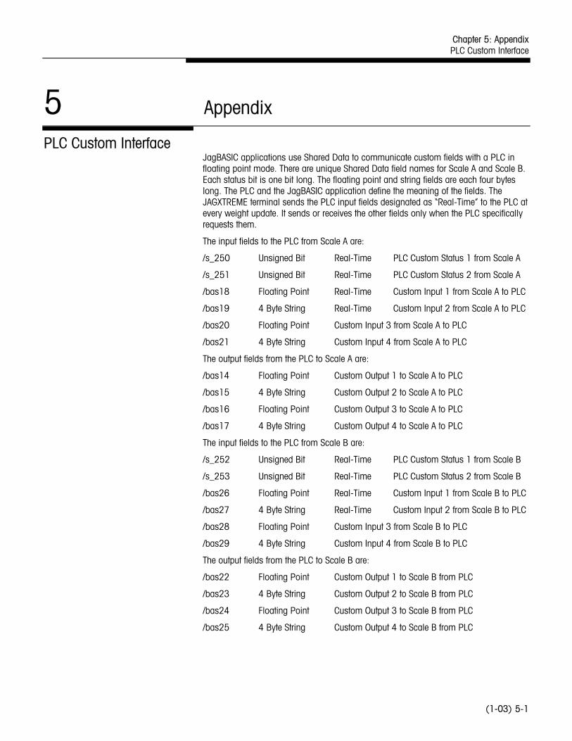
Chapter 5: Appendix PLC Custom Interface
5 Appendix
PLC Custom Interface JagBASIC applications use Shared Data to communicate custom fields with a PLC in floating point mode. There are unique Shared Data field names for Scale A and Scale B. Each status bit is one bit long. The floating point and string fields are each four bytes long. The PLC and the JagBASIC application define the meaning of the fields. The JAGXTREME terminal sends the PLC input fields designated as “Real-Time” to the PLC at every weight update. It sends or receives the other fields only when the PLC specifically requests them.
The input fields to the PLC from Scale A are:
/s_250 Unsigned Bit Real-Time PLC Custom Status 1 from Scale A
/s_251 Unsigned Bit Real-Time PLC Custom Status 2 from Scale A
/bas18 Floating Point Real-Time Custom Input 1 from Scale A to PLC
/bas19 4 Byte String Real-Time Custom Input 2 from Scale A to PLC
/bas20 Floating Point Custom Input 3 from Scale A to PLC
/bas21 4 Byte String Custom Input 4 from Scale A to PLC
The output fields from the PLC to Scale A are:
/bas14 Floating Point Custom Output 1 to Scale A to PLC
/bas15 4 Byte String Custom Output 2 to Scale A to PLC
/bas16 Floating Point Custom Output 3 to Scale A to PLC
/bas17 4 Byte String Custom Output 4 to Scale A to PLC
The input fields to the PLC from Scale B are:
/s_252 Unsigned Bit Real-Time PLC Custom Status 1 from Scale B
/s_253 Unsigned Bit Real-Time PLC Custom Status 2 from Scale B
/bas26 Floating Point Real-Time Custom Input 1 from Scale B to PLC
/bas27 4 Byte String Real-Time Custom Input 2 from Scale B to PLC
/bas28 Floating Point Custom Input 3 from Scale B to PLC
/bas29 4 Byte String Custom Input 4 from Scale B to PLC
The output fields from the PLC to Scale B are:
/bas22 Floating Point Custom Output 1 to Scale B from PLC
/bas23 4 Byte String Custom Output 2 to Scale B from PLC
/bas24 Floating Point Custom Output 3 to Scale B from PLC
/bas25 4 Byte String Custom Output 4 to Scale B from PLC
(1-03) 5-1
JAGXTREME PLC and Analog Output Interface Technical Manual
JagBASIC to Analog Output Shared Data Interface
JagBASIC variables may be used as sources for channel 1, or channel 2, or both channels. The JagBASIC variable for channel 1 is floating point variable /bas18. The JagBASIC source variable for channel 2 is floating point variable /bas20. JagBASIC may be used as a source for one channel and scale source for the other channel.
You must enter the zero and span preset values for the JagBASIC sources in the <Config Options> <Analog Output> setup menus. You can also trim the zero and span values for the JagBASIC sources, but the value that you are trimming must be set by a JagBASIC command before entering setup. This allows you to "calibrate" the Analog Output card.
For example, if you wish to trim the span value for a JagBASIC source for channel 2, you must enter the span value into /bas20. Then you can enter setup and use the Analog Output setup menu to trim the span value.
(1-03) 5-2

METTLER TOLEDO 1900 Polaris Parkway Columbus, Ohio 43240 Phone: (800) 786-0038 (614) 438-4511 Fax: (614) 438-4958 Internet: www.mt.com
D1288420A (01-05).00
METTLER TOLEDO® is registered trademark of Mettler-Toledo, Inc. ©2005 Mettler-Toledo Inc. Printed in USA