analog signal processing in transmission line … · analog signal processing in transmission line...
TRANSCRIPT
RADIOENGINEERING, VOL. 18, NO. 2, JUNE 2009 155
Analog Signal Processing in Transmission LineMetamaterial Structures
Shulabh GUPTA, Christophe CALOZ
Poly-Grames Research Center, Ecole Polytechnique de Montreal, Montreal, Quebec, Canada
Abstract. Several novel dispersion-engineered CRLH TLmetamaterial analog signal processing systems, exploitingthe broadband dispersive characteristics and design flexi-bility of CRLH TLs, are presented. These systems are ei-ther guided-wave or radiated-wave systems, and employ ei-ther the group velocity or the group velocity dispersion pa-rameters. The systems presented are: a frequency tunableimpulse delay line, a pulse-position modulator, a frequencydiscriminator and real-time Fourier transformer, pulse gen-erators, an analog real-time spectrum analyzer, a frequency-resolved electrical gating, a spatio-temporal Talbot effectimager, and analog true-time delayer. They represent a newclass of impulse-regime metamaterial structures, while pre-viously reported metamaterials were mostly restricted to theharmonic regime.
KeywordsAnalog signal processing, dispersion engineering,transmission line metamaterials, leaky-wave antennas,Talbot effect, real-time spectrum analyzers, pulse-position modulators, real-time Fourier transformation,true-time delayers.
1. IntroductionMetamaterial structures [1], thanks to their inherent
dispersive nature, have extended the possibilities of disper-sion engineering, relatively common in optics [2], to mi-crowave systems. Dispersion engineering consists in shap-ing the phase of electromagnetic waves to process signals inan analog fashion, leading to applications such as real-timeFourier transformers, pulse shapers, convolvers and corre-lators. This approach is particularly useful in applicationswhere digital solutions are not available, as for instancein very high frequency and high speed ultra-wideband mi-crowave systems. At microwaves, a very long history of“magnitude engineering” in the form of filter theory andtechniques exists, but no systematic approach has been re-ported for dispersion engineering, except for all-pass filtersrestricted to flat group delay designs [3].
Composite right/left-handed (CRLH) transmission line
(TL) metamaterial structures have been recently demon-strated to enable novel phase-engineered devices. Whereasresonant-type metamaterials, such as split-ring-resonatorand thin-wire structures cannot support impulse operationdue to their narrow bandwidth, CRLH TL metamaterials,which have already been extensively used in narrow-bandapplications, have a potential for unique impulse devices andsystems, due to their very broadband characteristics.
This paper proposes the principles of CRLH TL meta-material dispersion engineering and presents several corre-sponding guided-wave and radiated-wave applications.
2. Dispersion Engineering
2.1 ConceptIn any dispersive medium, the group velocity vg is
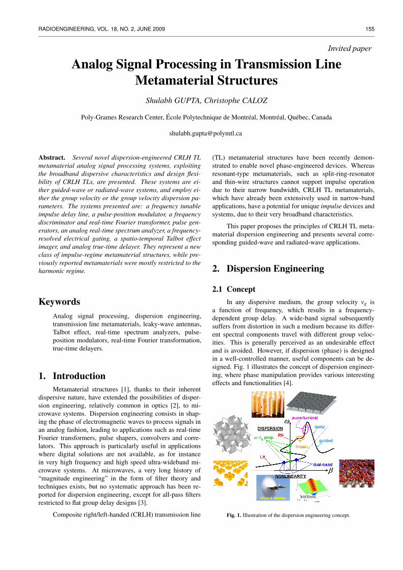
a function of frequency, which results in a frequency-dependent group delay. A wide-band signal subsequentlysuffers from distortion in such a medium because its differ-ent spectral components travel with different group veloc-ities. This is generally perceived as an undesirable effectand is avoided. However, if dispersion (phase) is designedin a well-controlled manner, useful components can be de-signed. Fig. 1 illustrates the concept of dispersion engineer-ing, where phase manipulation provides various interestingeffects and functionalities [4].
Fig. 1. Illustration of the dispersion engineering concept.
156 S. GUPTA, C. CALOZ, ANALOG SIGNAL PROCESSING IN TRANSMISSION LINE METAMATERIAL STRUCTURES
The dispersion relation β(ω) of a medium can be ex-panded in Taylor series about a center (or carrier) frequencyωc as follows:
β(ω) = β0 +β1(ω−ωc)+12(ω−ωc)2 + ... (1)
where βn(ω) =dnβ(ω)
dωn
∣∣∣∣ω=ωc
.
The Taylor series coefficients β0, β1 and β2 represent thephase velocity parameter, the group velocity parameter, andthe group velocity dispersion, respectively. β
−11 is the prop-
agation velocity, while β2 is a measure of the dispersionstrength. Based on this Taylor expansion, various systemscan be designed by using different Taylor coefficients, asshown in Tab. 1.
2.2 Microwave Dispersive DevicesIn microwave applications, dispersion can be achieved
using the different technologies such as surface acousticwave (SAW) devices, magneto-static wave (MSW) devicesand reflection-type devices such as chirped microstrip lineand coupler structures. Each of these technologies has ad-vantages and disadvantages.
SAW devices [5], thanks to their slow-wave character-istics, provide large delays (≈ 1µs), and hence a large time-bandwidth product, while also having a compact size. How-ever, they are restricted to narrow-band (2 GHz) and low-frequency applications (< 2 GHz) due to limitations of cur-rent photolythography processes.
MSW devices [6] can be employed for high-frequencyand wide-band operation, while also achieving high time-bandwidth product. However, in addition to being lossy, theyrequire a permanent magnet, which is bulky and renders pla-nar fabrication difficult.
In contrast to the transmission-type SAW and MSWstructures, reflection-type structures, such as multi-sectioncoupler based structures and chirped microstrip lines, havealso been reported. Coupler-based structures are composedof a number of series-connected coupled-line couplers eachoperating at contiguous frequencies. Thus, high frequency(≈ 10 GHz) and wide-band (≈ 3 GHz) operation can beachieved. However, the bandwidth is dependent on the sizeof the structure, i.e. more couplers leads to larger band-width, which also leads to long and extremely lossy struc-tures. In order to decrease loss, high-temperature supercon-ductors (HTS), requiring cryogenics, must be utilized, re-sulting in complex and expensive devices [7]
On the other hand, the chirped microstrip line [8, 9] isa simple and planar structure, which utilizes Bragg reflec-tions based on impedance mismatch. However, similar tothe coupled-line structure, its bandwidth is also dependenton size, while also being highly lossy due its operation inthe stop-band and thus requiring amplifiers.
Recently, CRLH TL metamaterial structures have been
demonstrated to offer several benefits compared to the con-ventional approaches for dispersion-engineered microwavedevices [4].
2.3 Transmission Line MetamaterialsThe CRLH artificial TL is composed of right-handed
elements (LR, CR) and left-handed elements (LL, CL) and ischaracterized by the following dispersion relation [1]:
β(ω) =1p
cos−1(
1− χ
2
)with χ =
(ω
ωR
)2
+(
ωL
ω
)2−κω
2L (2)
where κ = LLCR + LRCL, ωR = 1/√
LRCR, ωL = 1/√
LLCL,and p is the unit cell size or period, and by the Blochimpedance
ZB = ZL
√√√√ (ω/ωse)2−1(ω/ωsh)2−1
− ωL
2ω
[(ω
ωse
)2
−1
]2
(3)
where ωse = 1/√
LRCL and ωsh = 1/√
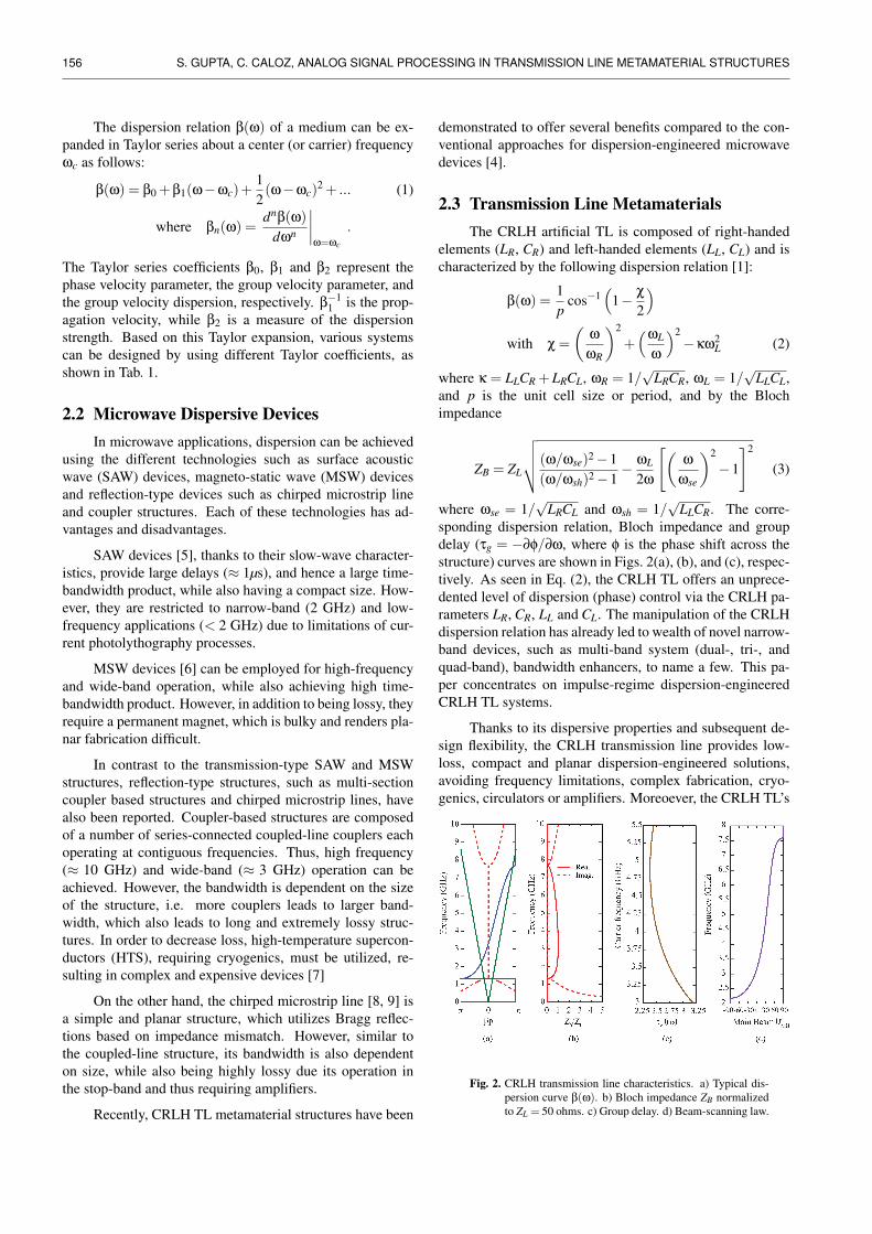
LLCR. The corre-sponding dispersion relation, Bloch impedance and groupdelay (τg = −∂φ/∂ω, where φ is the phase shift across thestructure) curves are shown in Figs. 2(a), (b), and (c), respec-tively. As seen in Eq. (2), the CRLH TL offers an unprece-dented level of dispersion (phase) control via the CRLH pa-rameters LR, CR, LL and CL. The manipulation of the CRLHdispersion relation has already led to wealth of novel narrow-band devices, such as multi-band system (dual-, tri-, andquad-band), bandwidth enhancers, to name a few. This pa-per concentrates on impulse-regime dispersion-engineeredCRLH TL systems.
Thanks to its dispersive properties and subsequent de-sign flexibility, the CRLH transmission line provides low-loss, compact and planar dispersion-engineered solutions,avoiding frequency limitations, complex fabrication, cryo-genics, circulators or amplifiers. Moreoever, the CRLH TL’s
Fig. 2. CRLH transmission line characteristics. a) Typical dis-persion curve β(ω). b) Bloch impedance ZB normalizedto ZL = 50 ohms. c) Group delay. d) Beam-scanning law.
RADIOENGINEERING, VOL. 18, NO. 2, JUNE 2009 157
β0 (phase velocity parameter) β1 (group velocity parameter) β2 (group velocity dispersion)
multiband systems [1] CW and impulse delay line real-time Fourier transformer(Sec. 3.1) (RTFT) (Sec. 3.3)
bandwidth enhancement [1] pulse position modulator (PPM) temporal Talbot effect(Sec. 3.2) (Sec. 3.4)
(not discussed here) CRLH resonator based pulse generator real-time spectrum analyzers(Sec. 3.4) (RTSA) (Sec. 4.1)
true time delayers (TTD) frequency resolved electrical gating(Sec. 4.4) (FREG) (Sec. 4.2)
spatio-temporal Talbot effect (Sec. 4.3)
Tab. 1. Dispersive system classification based on the Taylor coefficients of the dispersion relation – Eq. (2).
operational frequency and bandwidth dependent only ona single unit cell’s right/left-handed capacitor and inductorvalues [1]. Thus, a compact CRLH TL can be designed tooperate at high frequencies while also exhibiting wide band-width, as shown by the relatively constant Bloch impedancein Fig. 2(b).
A CRLH TL can also be operated in a radiative leaky-wave mode when open to free space, since the CRLH disper-sion curve (Fig. 2(a)) penetrates into the fast-wave region,ω ∈ [ωBF ,ωEF ]. The resulting leaky-wave antenna (LWA)radiates from backfire (θ =−90) to endfire (θ = +90) in-cluding broadside (θ = 0) as frequency is scanned from ωBF(where β =−k0) to ωEF (where β = +k0) [19, 1], followingthe scanning law
θ(ω) = sin−1[
β(ω)k0
], (4)
which is plotted in Fig. 2(d). The CRLH LWA offers threebenefits: 1) full-space radiation from backfire to endfire in-cluding broadside in the fundamental mode, offering a sim-ple and real-time frequency-space separation mechanism;2) frequency and bandwidth scalability, allowing to handleultra-wideband signals; 3) simple and compact design andimplementation.
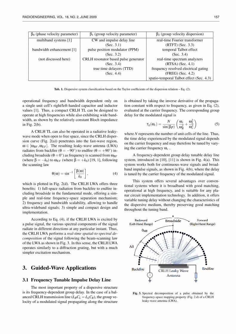
According to Eq. (4), if the CRLH LWA is excited bya pulse signal, the various spectral components of the signalradiate in different directions at any particular instant. Thus,the CRLH LWA performs a real-time spatial-to-spectral de-composition of the signal following the beam-scanning lawof the LWA as shown in Fig. 3. In this sense, the CRLH LWAoperates similarly to a diffraction grating, but with a muchsimpler excitation mechanism.
3. Guided-Wave Applications
3.1 Frequency Tunable Impulse Delay LineThe most important property of a dispersive structure
is its frequency-dependent group delay. In the case of a bal-anced CRLH transmission line (LRCL = LLCR), the group ve-locity of a modulated signal propagating along the structure
is obtained by taking the inverse derivative of the propaga-tion constant with respect to frequency, as given in Eq. (2),evaluated at the carrier frequency. The corresponding groupdelay for the modulated signal is
τg(ωc) =N
sin(βp)
(ωc
ω2R
+ω2
Lω3
c
)(5)
where N represents the number of unit cells of the line. Thus,the time delay experienced by the modulated signal dependson the carrier frequency and may therefore be tuned by vary-ing the carrier frequency ωc .
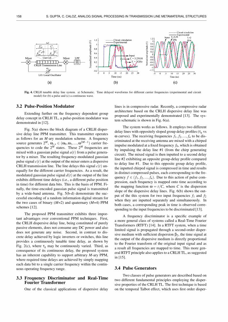
A frequency-dependent group delay tunable delay linesystem, introduced in [10], [11] is shown in Fig. 4(a). Thissystem works both for continuous-wave signals and broad-band impulse signals, as shown in Fig. 4(b), where the delayis tuned by the carrier frequency of the modulated signal.
This system offers several advantages over conven-tional systems where it is broadband with good matching,operational at high frequency, and is suitable for any pla-nar circuit implementation technology. In addition, it offersvariable tuning delay without changing the characteristics ofthe dispersive medium, thereby preserving good matchingthroughout the tuning band.
Fig. 3. Spectral decomposition of a pulse obtained by thefrequency-space mapping property (Fig. 2.d) of a CRLHleaky-wave antenna (LWA).
158 S. GUPTA, C. CALOZ, ANALOG SIGNAL PROCESSING IN TRANSMISSION LINE METAMATERIAL STRUCTURES
Fig. 4. CRLH tunable delay line system. a) Schematic. Time delayed waveforms for different carrier frequencies (experimental and circuitmodel) for (b) a pulse and (c) a continuous wave.
3.2 Pulse-Position ModulatorExtending further on the frequency dependent group
delay concept in CRLH TL, a pulse-position modulator wasdemonstrated in [12].
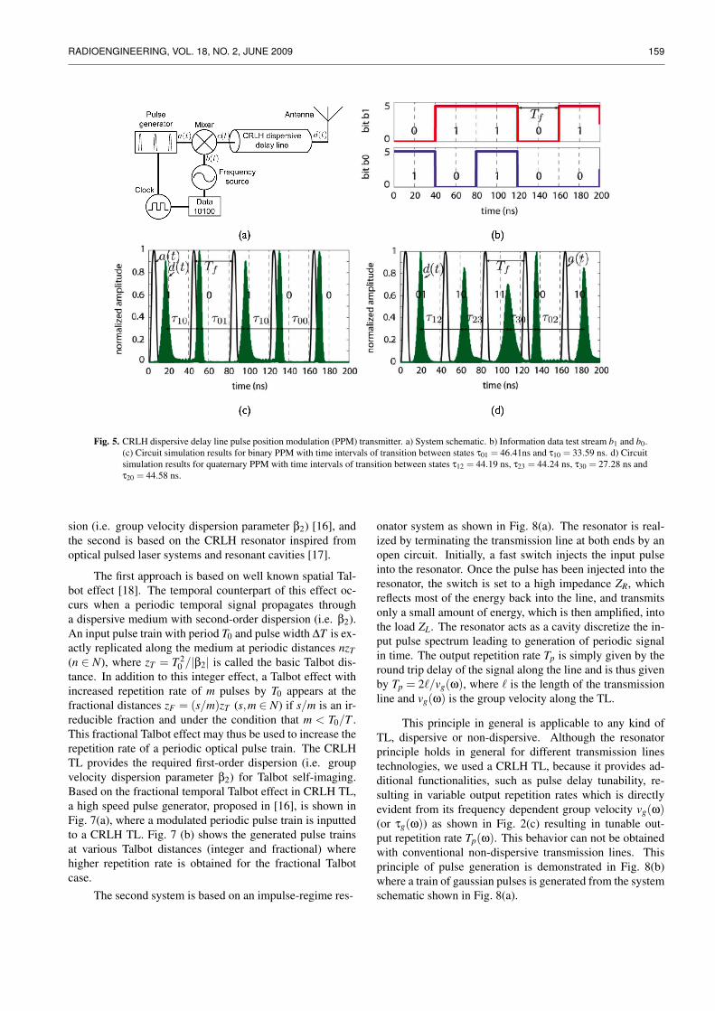
Fig. 5(a) shows the block diagram of a CRLH disper-sive delay line PPM transmitter. This transmitter operatesas follows for an M-ary modulation scheme. A frequencysource generates 2M , ωc,s ∈ (ω0,ω1, ...,ω
2M−1) carrier fre-quencies to code the 2M states. These 2M frequencies aremixed with a gaussian pulse signal a(t) from a pulse genera-tor by a mixer. The resulting frequency-modulated gaussianpulse signal c(t) at the output of the mixer enters a dispersiveCRLH transmission line. The line delays this signal c(t) un-equally for the different carrier frequencies. As a result, themodulated gaussian pulse signal d(t) at the output of the lineexhibits different time delays (i.e., a different pulse positionin time) for different data bits. This is the basis of PPM. Fi-nally, the time-encoded gaussian pulse signal is transmittedby a wide-band antenna. Fig. 5(b-d) demonstrate the suc-cessful encoding of a random information digital stream forthe two cases of binary (M=2) and quaternary (M=4) PPMschemes [12].
The proposed PPM transmitter exhibits three impor-tant advantages over conventional PPM techniques. First,the CRLH dispersive delay line, being constituted of purelypassive elements, does not consume any DC power and alsodoes not generate any noise. Second, in contrast to dis-crete delay achieved by logic inverters or switches, this lineprovides a continuously tunable time delay, as shown byFig. 2(c), where τg may be continuously varied. Third, asconsequence of its continuous delay, the proposed systemhas an inherent capability to support arbitrary M-ary PPM,where required time delays are achieved by simply mappingeach data bit to a single carrier frequency within the contin-uous operating frequency range.
3.3 Frequency Discriminator and Real-TimeFourier TransformerOne of the classical applications of dispersive delay
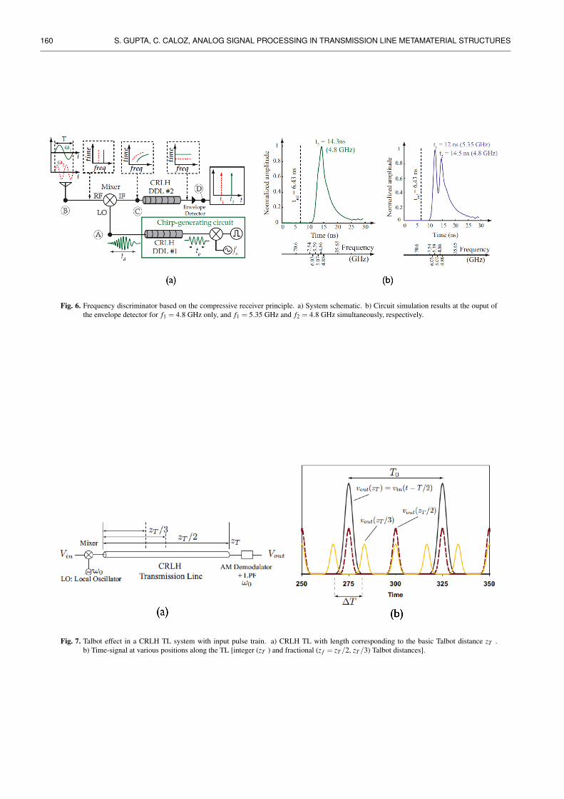
lines is in compressive radar. Recently, a compressive radararchitecture based on the CRLH dispersive delay line wasproposed and experimentally demonstrated [13]. The sys-tem schematic is shown in Fig. 6(a).
The system works as follows. It employs two differentdelay lines with oppositely sloped group delay profiles (τg vsω curves). The receiving frequencies f1, f2, ..., fn to be dis-criminated at the receiving antenna are mixed with a chirpedimpulse modulated at a fixed frequency f0, which is obtainedby impulsing the delay line #1 (from the chirp generatingcircuit). The mixed signal is then inputted to a second delayline #2 exhibiting an opposite group-delay profile comparedto delay line #1. Due to this opposite group delay profile,the inputted chirped signal is compressed in time and resultsin distinct compressed pulses, each corresponding to the fre-quency f ∈ ( f1, f2, ..., fn). Due to this action of pulse com-pression, each frequency is mapped onto time according tothe mapping function ω = t/C, where C is the dispersionslope of the dispersive delay lines. Fig. 6(b) shows the out-put of the this system for two input frequencies f1 and f2when they are inputted separately and simultaneously. Inboth cases, a corresponding peak in time is observed corre-sponding to the input frequencies to be discriminated [13].
A frequency discriminator is a specific example ofa more general class of systems called a Real-Time FourierTransformers (RTFT) [14]. In a RTFT system, when a timelimited signal is propagated through a second-order disper-sive medium with sufficient dispersion β2, the time signal atthe output of the dispersive medium is directly proportionalto the Fourier transform of the original input signal and asa result all frequencies are mapped to time. This more gen-eral RTFT principle also applies to a CRLH TL, as suggestedin [15].
3.4 Pulse GeneratorsTwo classes of pulse generators are described based on
two different fundamental principles employing the disper-sive properties of the CRLH TL. The first technique is basedon the temporal Talbot effect, which uses first order disper-
RADIOENGINEERING, VOL. 18, NO. 2, JUNE 2009 159
Fig. 5. CRLH dispersive delay line pulse position modulation (PPM) transmitter. a) System schematic. b) Information data test stream b1 and b0.(c) Circuit simulation results for binary PPM with time intervals of transition between states τ01 = 46.41ns and τ10 = 33.59 ns. d) Circuitsimulation results for quaternary PPM with time intervals of transition between states τ12 = 44.19 ns, τ23 = 44.24 ns, τ30 = 27.28 ns andτ20 = 44.58 ns.
sion (i.e. group velocity dispersion parameter β2) [16], andthe second is based on the CRLH resonator inspired fromoptical pulsed laser systems and resonant cavities [17].
The first approach is based on well known spatial Tal-bot effect [18]. The temporal counterpart of this effect oc-curs when a periodic temporal signal propagates througha dispersive medium with second-order dispersion (i.e. β2).An input pulse train with period T0 and pulse width ∆T is ex-actly replicated along the medium at periodic distances nzT(n ∈ N), where zT = T 2
0 /|β2| is called the basic Talbot dis-tance. In addition to this integer effect, a Talbot effect withincreased repetition rate of m pulses by T0 appears at thefractional distances zF = (s/m)zT (s,m ∈ N) if s/m is an ir-reducible fraction and under the condition that m < T0/T .This fractional Talbot effect may thus be used to increase therepetition rate of a periodic optical pulse train. The CRLHTL provides the required first-order dispersion (i.e. groupvelocity dispersion parameter β2) for Talbot self-imaging.Based on the fractional temporal Talbot effect in CRLH TL,a high speed pulse generator, proposed in [16], is shown inFig. 7(a), where a modulated periodic pulse train is inputtedto a CRLH TL. Fig. 7 (b) shows the generated pulse trainsat various Talbot distances (integer and fractional) wherehigher repetition rate is obtained for the fractional Talbotcase.
The second system is based on an impulse-regime res-
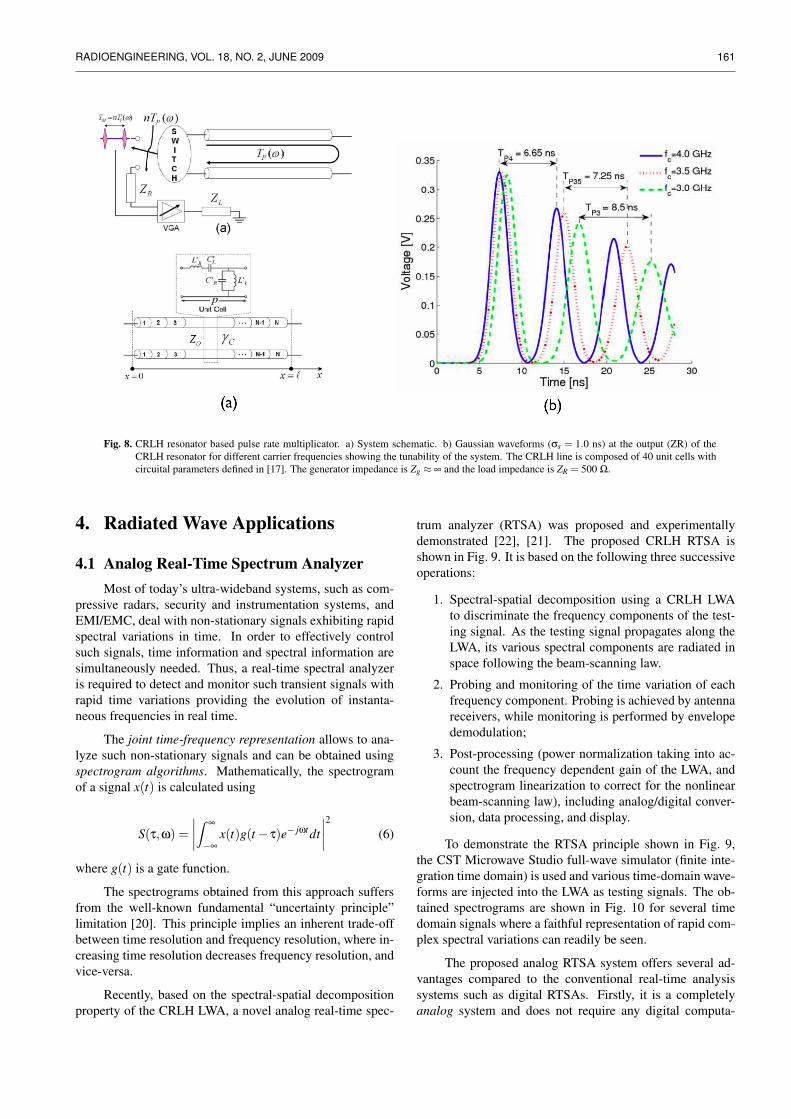
onator system as shown in Fig. 8(a). The resonator is real-ized by terminating the transmission line at both ends by anopen circuit. Initially, a fast switch injects the input pulseinto the resonator. Once the pulse has been injected into theresonator, the switch is set to a high impedance ZR, whichreflects most of the energy back into the line, and transmitsonly a small amount of energy, which is then amplified, intothe load ZL. The resonator acts as a cavity discretize the in-put pulse spectrum leading to generation of periodic signalin time. The output repetition rate Tp is simply given by theround trip delay of the signal along the line and is thus givenby Tp = 2`/vg(ω), where ` is the length of the transmissionline and vg(ω) is the group velocity along the TL.
This principle in general is applicable to any kind ofTL, dispersive or non-dispersive. Although the resonatorprinciple holds in general for different transmission linestechnologies, we used a CRLH TL, because it provides ad-ditional functionalities, such as pulse delay tunability, re-sulting in variable output repetition rates which is directlyevident from its frequency dependent group velocity vg(ω)(or τg(ω)) as shown in Fig. 2(c) resulting in tunable out-put repetition rate Tp(ω). This behavior can not be obtainedwith conventional non-dispersive transmission lines. Thisprinciple of pulse generation is demonstrated in Fig. 8(b)where a train of gaussian pulses is generated from the systemschematic shown in Fig. 8(a).
160 S. GUPTA, C. CALOZ, ANALOG SIGNAL PROCESSING IN TRANSMISSION LINE METAMATERIAL STRUCTURES
Fig. 6. Frequency discriminator based on the compressive receiver principle. a) System schematic. b) Circuit simulation results at the ouput ofthe envelope detector for f1 = 4.8 GHz only, and f1 = 5.35 GHz and f2 = 4.8 GHz simultaneously, respectively.
Fig. 7. Talbot effect in a CRLH TL system with input pulse train. a) CRLH TL with length corresponding to the basic Talbot distance zT .b) Time-signal at various positions along the TL [integer (zT ) and fractional (z f = zT /2, zT /3) Talbot distances].
RADIOENGINEERING, VOL. 18, NO. 2, JUNE 2009 161
Fig. 8. CRLH resonator based pulse rate multiplicator. a) System schematic. b) Gaussian waveforms (σs = 1.0 ns) at the output (ZR) of theCRLH resonator for different carrier frequencies showing the tunability of the system. The CRLH line is composed of 40 unit cells withcircuital parameters defined in [17]. The generator impedance is Zg ≈ ∞ and the load impedance is ZR = 500 Ω.
4. Radiated Wave Applications
4.1 Analog Real-Time Spectrum AnalyzerMost of today’s ultra-wideband systems, such as com-
pressive radars, security and instrumentation systems, andEMI/EMC, deal with non-stationary signals exhibiting rapidspectral variations in time. In order to effectively controlsuch signals, time information and spectral information aresimultaneously needed. Thus, a real-time spectral analyzeris required to detect and monitor such transient signals withrapid time variations providing the evolution of instanta-neous frequencies in real time.
The joint time-frequency representation allows to ana-lyze such non-stationary signals and can be obtained usingspectrogram algorithms. Mathematically, the spectrogramof a signal x(t) is calculated using
S(τ,ω) =∣∣∣∣Z ∞
−∞
x(t)g(t− τ)e− jωtdt∣∣∣∣2 (6)
where g(t) is a gate function.
The spectrograms obtained from this approach suffersfrom the well-known fundamental “uncertainty principle”limitation [20]. This principle implies an inherent trade-offbetween time resolution and frequency resolution, where in-creasing time resolution decreases frequency resolution, andvice-versa.
Recently, based on the spectral-spatial decompositionproperty of the CRLH LWA, a novel analog real-time spec-
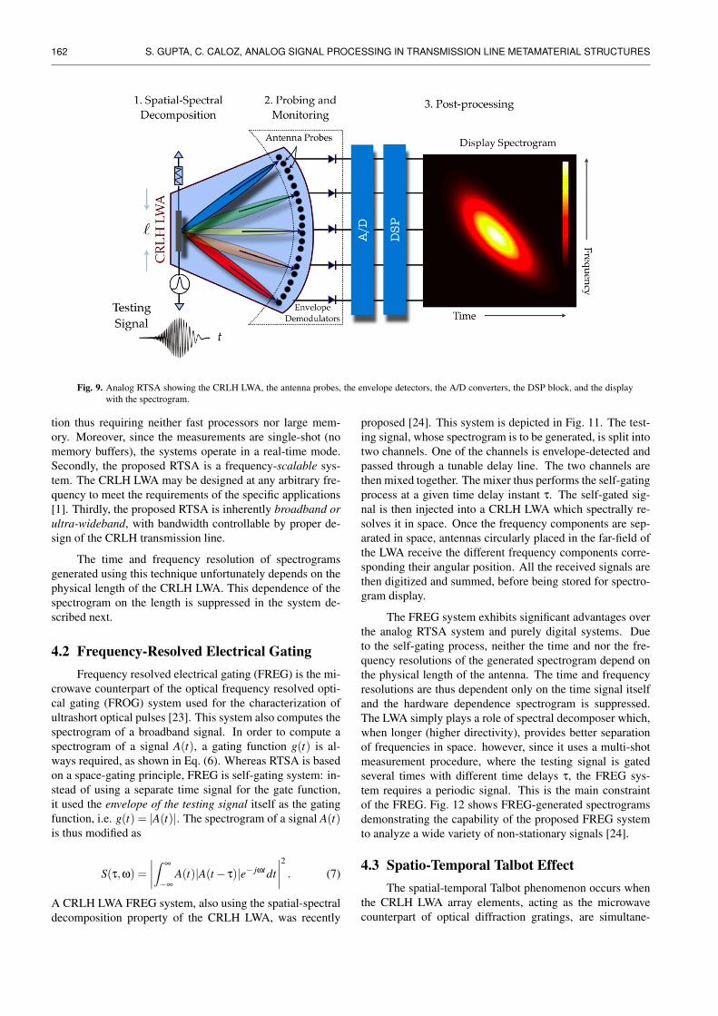
trum analyzer (RTSA) was proposed and experimentallydemonstrated [22], [21]. The proposed CRLH RTSA isshown in Fig. 9. It is based on the following three successiveoperations:
1. Spectral-spatial decomposition using a CRLH LWAto discriminate the frequency components of the test-ing signal. As the testing signal propagates along theLWA, its various spectral components are radiated inspace following the beam-scanning law.
2. Probing and monitoring of the time variation of eachfrequency component. Probing is achieved by antennareceivers, while monitoring is performed by envelopedemodulation;
3. Post-processing (power normalization taking into ac-count the frequency dependent gain of the LWA, andspectrogram linearization to correct for the nonlinearbeam-scanning law), including analog/digital conver-sion, data processing, and display.
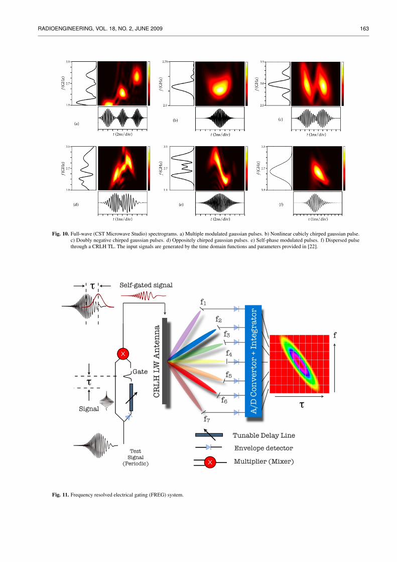
To demonstrate the RTSA principle shown in Fig. 9,the CST Microwave Studio full-wave simulator (finite inte-gration time domain) is used and various time-domain wave-forms are injected into the LWA as testing signals. The ob-tained spectrograms are shown in Fig. 10 for several timedomain signals where a faithful representation of rapid com-plex spectral variations can readily be seen.
The proposed analog RTSA system offers several ad-vantages compared to the conventional real-time analysissystems such as digital RTSAs. Firstly, it is a completelyanalog system and does not require any digital computa-
162 S. GUPTA, C. CALOZ, ANALOG SIGNAL PROCESSING IN TRANSMISSION LINE METAMATERIAL STRUCTURES
Fig. 9. Analog RTSA showing the CRLH LWA, the antenna probes, the envelope detectors, the A/D converters, the DSP block, and the displaywith the spectrogram.
tion thus requiring neither fast processors nor large mem-ory. Moreover, since the measurements are single-shot (nomemory buffers), the systems operate in a real-time mode.Secondly, the proposed RTSA is a frequency-scalable sys-tem. The CRLH LWA may be designed at any arbitrary fre-quency to meet the requirements of the specific applications[1]. Thirdly, the proposed RTSA is inherently broadband orultra-wideband, with bandwidth controllable by proper de-sign of the CRLH transmission line.
The time and frequency resolution of spectrogramsgenerated using this technique unfortunately depends on thephysical length of the CRLH LWA. This dependence of thespectrogram on the length is suppressed in the system de-scribed next.
4.2 Frequency-Resolved Electrical GatingFrequency resolved electrical gating (FREG) is the mi-
crowave counterpart of the optical frequency resolved opti-cal gating (FROG) system used for the characterization ofultrashort optical pulses [23]. This system also computes thespectrogram of a broadband signal. In order to compute aspectrogram of a signal A(t), a gating function g(t) is al-ways required, as shown in Eq. (6). Whereas RTSA is basedon a space-gating principle, FREG is self-gating system: in-stead of using a separate time signal for the gate function,it used the envelope of the testing signal itself as the gatingfunction, i.e. g(t) = |A(t)|. The spectrogram of a signal A(t)is thus modified as
S(τ,ω) =∣∣∣∣Z ∞
−∞
A(t)|A(t− τ)|e− jωtdt∣∣∣∣2 . (7)
A CRLH LWA FREG system, also using the spatial-spectraldecomposition property of the CRLH LWA, was recently
proposed [24]. This system is depicted in Fig. 11. The test-ing signal, whose spectrogram is to be generated, is split intotwo channels. One of the channels is envelope-detected andpassed through a tunable delay line. The two channels arethen mixed together. The mixer thus performs the self-gatingprocess at a given time delay instant τ. The self-gated sig-nal is then injected into a CRLH LWA which spectrally re-solves it in space. Once the frequency components are sep-arated in space, antennas circularly placed in the far-field ofthe LWA receive the different frequency components corre-sponding their angular position. All the received signals arethen digitized and summed, before being stored for spectro-gram display.
The FREG system exhibits significant advantages overthe analog RTSA system and purely digital systems. Dueto the self-gating process, neither the time and nor the fre-quency resolutions of the generated spectrogram depend onthe physical length of the antenna. The time and frequencyresolutions are thus dependent only on the time signal itselfand the hardware dependence spectrogram is suppressed.The LWA simply plays a role of spectral decomposer which,when longer (higher directivity), provides better separationof frequencies in space. however, since it uses a multi-shotmeasurement procedure, where the testing signal is gatedseveral times with different time delays τ, the FREG sys-tem requires a periodic signal. This is the main constraintof the FREG. Fig. 12 shows FREG-generated spectrogramsdemonstrating the capability of the proposed FREG systemto analyze a wide variety of non-stationary signals [24].
4.3 Spatio-Temporal Talbot EffectThe spatial-temporal Talbot phenomenon occurs when
the CRLH LWA array elements, acting as the microwavecounterpart of optical diffraction gratings, are simultane-
RADIOENGINEERING, VOL. 18, NO. 2, JUNE 2009 163
Fig. 10. Full-wave (CST Microwave Studio) spectrograms. a) Multiple modulated gaussian pulses. b) Nonlinear cubicly chirped gaussian pulse.c) Doubly negative chirped gaussian pulses. d) Oppositely chirped gaussian pulses. e) Self-phase modulated pulses. f) Dispersed pulsethrough a CRLH TL. The input signals are generated by the time domain functions and parameters provided in [22].
Fig. 11. Frequency resolved electrical gating (FREG) system.
164 S. GUPTA, C. CALOZ, ANALOG SIGNAL PROCESSING IN TRANSMISSION LINE METAMATERIAL STRUCTURES
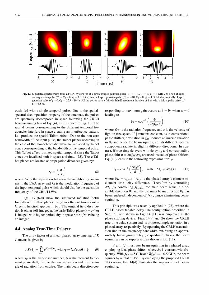
Fig. 12. Simulated spectrograms from a FREG system for a) a down-chirped gaussian pulse (C1 =−10, C2 = 0, f0 = 4 GHz), b) a non-chirpedsuper-gaussian pulse (C1 =C2 = 0, f0 = 3 GHz), c) an up-chirped gaussian pulse (C1 = +10, C2 = 0, f0 = 4 GHz), d) a cubically chirpedgaussian pulse (C1 = 0, C2 = 0.25×1028). All the pulses have a full width half maximum duration of 1 ns with a initial pulse offset oft0 = 6.5 ns.
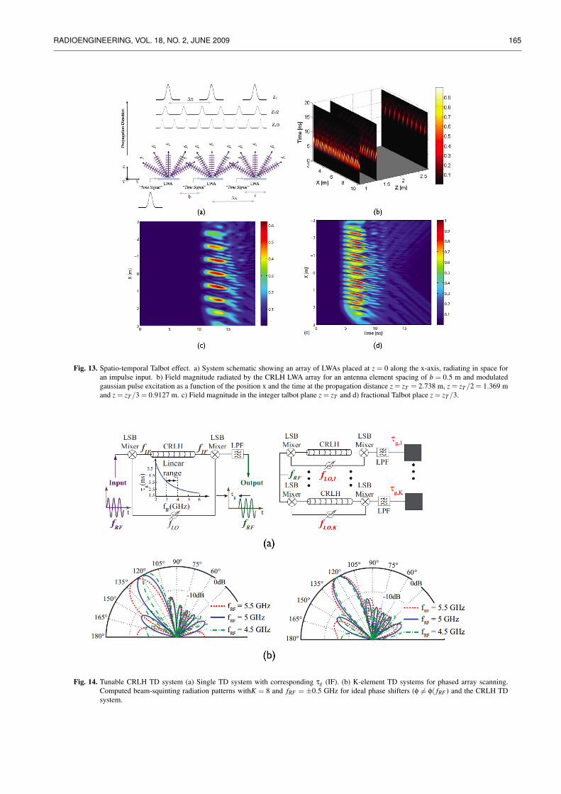
ously fed with a single temporal pulse. Due to the spatial-spectral decomposition property of the antennas, the pulsesare spectrally decomposed in space following the CRLHbeam-scanning law of Eq. (4), as illustrated in Fig. 13. Thespatial beams corresponding to the different temporal fre-quencies interfere in space creating an interference pattern,i.e. produce the spatial Talbot effect. Due to the non-zerobandwidth of the input pulse, the Talbot planes occurring inthe case of the monochromatic wave are replaced by Talbotzones corresponding to the bandwidth of the temporal pulse.This Talbot effect is mixed spatial-temporal since the Talbotzones are localized both in space and time. [25]. These Tal-bot planes are located at propagation distances given by:
zT =sm
∆x2
λ0(8)
where ∆x is the separation between the neighboring anten-nas in the LWA array and λ0 is the modulation frequency ofthe input temporal pulse which should also be the transitionfrequency of the CRLH LWA.
Figs. 13 (b-d) show the simulated radiation fieldsfor different Talbot planes using an efficient time-domainGreen’s function approach [26]. The original field distribu-tion is either self-imaged at the basic Talbot plane (z = zT ) oris imaged with higher periodicity in space z = zT /m, m beingan integer.
4.4 Analog True-Time DelayerThe array factor of a linear phased-array antenna of K
elements is given by
AF(θ) =N
∑n=1
e j(n−1)ϕ, with ϕ = k0d cosθ+φ (9)
where k0 is the free-space number, φ is the element to ele-ment phase shift, d is the element separation and θ is the an-gle of radiation from endfire. The main beam direction cor-
responding to maximum gain occurs at θ = θ0 when ϕ = 0leading to
θ0 = cos−1(
φc2π fRF d
)(10)
where fRF is the radiation frequency and c is the velocity oflight in free space. If φ remains constant, as in conventionalphase shifters, a variation in fRF induces an inverse variationin θ0 and hence the beam squints, i.e. its different spectralcomponents radiate in slightly different directions. In con-trast, if true-time delayers with delay τg and correspondingphase shift φ = 2π fRF ∆τg are used instead of phase shifters,Eq. (10) leads to the following expression for θ0:
θ0 = cos−1(
∆τgcd
), with ∆τg 6= ∆τg( f ) (11)
where δτg = τg,n+1− τg,n is the phased array’s element-to-element time delay difference. Therefore by controlling∆τg (by controlling fLO,K), the main beam scans in a de-sirable direction θ0 and the the main beam direction θ0 hasbeen rendered independent of fRF , hence eliminating beam-squinting.
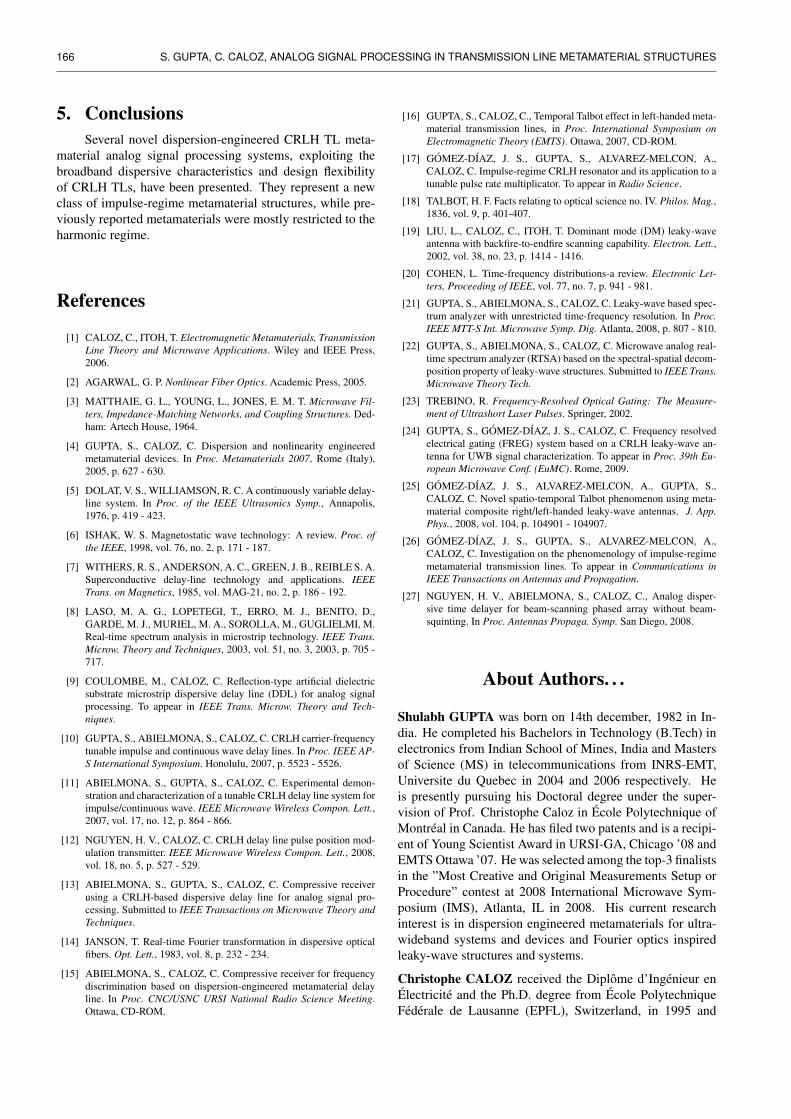
This principle was recently applied in [27], where theCRLH based tunable delay line configuration described inSec. 3.1 and shown in Fig. 14 [11] was employed as thephase shifting device. Figs. 14(a) and (b) show the CRLHtrue-time delay system and its proposed implementation in aphased array, respectively. By operating the CRLH transmis-sion line in the frequency bandwidth exhibiting an approx-imately linear group delay (or quadratic phase), the beamsquinting can be suppressed, as shown in Eq. (11).
Fig. 14(c) illustrates beam-squinting in a phased arrayemploying ideal phase shifters where ∆φ is constant with fre-quency. With fRF = 5 GHz and δ fRF =±0.5 GHz, the beamsquints by a total of 15. By employing the proposed CRLHTD system, Fig. 14(d) illustrates the suppression of beam-squinting.
RADIOENGINEERING, VOL. 18, NO. 2, JUNE 2009 165
Fig. 13. Spatio-temporal Talbot effect. a) System schematic showing an array of LWAs placed at z = 0 along the x-axis, radiating in space foran impulse input. b) Field magnitude radiated by the CRLH LWA array for an antenna element spacing of b = 0.5 m and modulatedgaussian pulse excitation as a function of the position x and the time at the propagation distance z = zT = 2.738 m, z = zT /2 = 1.369 mand z = zT /3 = 0.9127 m. c) Field magnitude in the integer talbot plane z = zT and d) fractional Talbot place z = zT /3.
Fig. 14. Tunable CRLH TD system (a) Single TD system with corresponding τg (IF). (b) K-element TD systems for phased array scanning.Computed beam-squinting radiation patterns withK = 8 and fRF = ±0.5 GHz for ideal phase shifters (φ 6= φ( fRF ) and the CRLH TDsystem.
166 S. GUPTA, C. CALOZ, ANALOG SIGNAL PROCESSING IN TRANSMISSION LINE METAMATERIAL STRUCTURES
5. ConclusionsSeveral novel dispersion-engineered CRLH TL meta-
material analog signal processing systems, exploiting thebroadband dispersive characteristics and design flexibilityof CRLH TLs, have been presented. They represent a newclass of impulse-regime metamaterial structures, while pre-viously reported metamaterials were mostly restricted to theharmonic regime.
References
[1] CALOZ, C., ITOH, T. Electromagnetic Metamaterials, TransmissionLine Theory and Microwave Applications. Wiley and IEEE Press,2006.
[2] AGARWAL, G. P. Nonlinear Fiber Optics. Academic Press, 2005.
[3] MATTHAIE, G. L., YOUNG, L., JONES, E. M. T. Microwave Fil-ters, Impedance-Matching Networks, and Coupling Structures. Ded-ham: Artech House, 1964.
[4] GUPTA, S., CALOZ, C. Dispersion and nonlinearity engineeredmetamaterial devices. In Proc. Metamaterials 2007, Rome (Italy),2005, p. 627 - 630.
[5] DOLAT, V. S., WILLIAMSON, R. C. A continuously variable delay-line system. In Proc. of the IEEE Ultrasonics Symp., Annapolis,1976, p. 419 - 423.
[6] ISHAK, W. S. Magnetostatic wave technology: A review. Proc. ofthe IEEE, 1998, vol. 76, no. 2, p. 171 - 187.
[7] WITHERS, R. S., ANDERSON, A. C., GREEN, J. B., REIBLE S. A.Superconductive delay-line technology and applications. IEEETrans. on Magnetics, 1985, vol. MAG-21, no. 2, p. 186 - 192.
[8] LASO, M. A. G., LOPETEGI, T., ERRO, M. J., BENITO, D.,GARDE, M. J., MURIEL, M. A., SOROLLA, M., GUGLIELMI, M.Real-time spectrum analysis in microstrip technology. IEEE Trans.Microw. Theory and Techniques, 2003, vol. 51, no. 3, 2003, p. 705 -717.
[9] COULOMBE, M., CALOZ, C. Reflection-type artificial dielectricsubstrate microstrip dispersive delay line (DDL) for analog signalprocessing. To appear in IEEE Trans. Microw. Theory and Tech-niques.
[10] GUPTA, S., ABIELMONA, S., CALOZ, C. CRLH carrier-frequencytunable impulse and continuous wave delay lines. In Proc. IEEE AP-S International Symposium. Honolulu, 2007, p. 5523 - 5526.
[11] ABIELMONA, S., GUPTA, S., CALOZ, C. Experimental demon-stration and characterization of a tunable CRLH delay line system forimpulse/continuous wave. IEEE Microwave Wireless Compon. Lett.,2007, vol. 17, no. 12, p. 864 - 866.
[12] NGUYEN, H. V., CALOZ, C. CRLH delay line pulse position mod-ulation transmitter. IEEE Microwave Wireless Compon. Lett., 2008,vol. 18, no. 5, p. 527 - 529.
[13] ABIELMONA, S., GUPTA, S., CALOZ, C. Compressive receiverusing a CRLH-based dispersive delay line for analog signal pro-cessing. Submitted to IEEE Transactions on Microwave Theory andTechniques.
[14] JANSON, T. Real-time Fourier transformation in dispersive opticalfibers. Opt. Lett., 1983, vol. 8, p. 232 - 234.
[15] ABIELMONA, S., CALOZ, C. Compressive receiver for frequencydiscrimination based on dispersion-engineered metamaterial delayline. In Proc. CNC/USNC URSI National Radio Science Meeting.Ottawa, CD-ROM.
[16] GUPTA, S., CALOZ, C., Temporal Talbot effect in left-handed meta-material transmission lines, in Proc. International Symposium onElectromagnetic Theory (EMTS). Ottawa, 2007, CD-ROM.
[17] GOMEZ-DIAZ, J. S., GUPTA, S., ALVAREZ-MELCON, A.,CALOZ, C. Impulse-regime CRLH resonator and its application to atunable pulse rate multiplicator. To appear in Radio Science.
[18] TALBOT, H. F. Facts relating to optical science no. IV. Philos. Mag.,1836, vol. 9, p. 401-407.
[19] LIU, L., CALOZ, C., ITOH, T. Dominant mode (DM) leaky-waveantenna with backfire-to-endfire scanning capability. Electron. Lett.,2002, vol. 38, no. 23, p. 1414 - 1416.
[20] COHEN, L. Time-frequency distributions-a review. Electronic Let-ters, Proceeding of IEEE, vol. 77, no. 7, p. 941 - 981.
[21] GUPTA, S., ABIELMONA, S., CALOZ, C. Leaky-wave based spec-trum analyzer with unrestricted time-frequency resolution. In Proc.IEEE MTT-S Int. Microwave Symp. Dig. Atlanta, 2008, p. 807 - 810.
[22] GUPTA, S., ABIELMONA, S., CALOZ, C. Microwave analog real-time spectrum analyzer (RTSA) based on the spectral-spatial decom-position property of leaky-wave structures. Submitted to IEEE Trans.Microwave Theory Tech.
[23] TREBINO, R. Frequency-Resolved Optical Gating: The Measure-ment of Ultrashort Laser Pulses. Springer, 2002.
[24] GUPTA, S., GOMEZ-DIAZ, J. S., CALOZ, C. Frequency resolvedelectrical gating (FREG) system based on a CRLH leaky-wave an-tenna for UWB signal characterization. To appear in Proc. 39th Eu-ropean Microwave Conf. (EuMC). Rome, 2009.
[25] GOMEZ-DIAZ, J. S., ALVAREZ-MELCON, A., GUPTA, S.,CALOZ, C. Novel spatio-temporal Talbot phenomenon using meta-material composite right/left-handed leaky-wave antennas. J. App.Phys., 2008, vol. 104, p. 104901 - 104907.
[26] GOMEZ-DIAZ, J. S., GUPTA, S., ALVAREZ-MELCON, A.,CALOZ, C. Investigation on the phenomenology of impulse-regimemetamaterial transmission lines. To appear in Communications inIEEE Transactions on Antennas and Propagation.
[27] NGUYEN, H. V., ABIELMONA, S., CALOZ, C., Analog disper-sive time delayer for beam-scanning phased array without beam-squinting. In Proc. Antennas Propaga. Symp. San Diego, 2008.
About Authors. . .
Shulabh GUPTA was born on 14th december, 1982 in In-dia. He completed his Bachelors in Technology (B.Tech) inelectronics from Indian School of Mines, India and Mastersof Science (MS) in telecommunications from INRS-EMT,Universite du Quebec in 2004 and 2006 respectively. Heis presently pursuing his Doctoral degree under the super-vision of Prof. Christophe Caloz in Ecole Polytechnique ofMontreal in Canada. He has filed two patents and is a recipi-ent of Young Scientist Award in URSI-GA, Chicago ’08 andEMTS Ottawa ’07. He was selected among the top-3 finalistsin the ”Most Creative and Original Measurements Setup orProcedure” contest at 2008 International Microwave Sym-posium (IMS), Atlanta, IL in 2008. His current researchinterest is in dispersion engineered metamaterials for ultra-wideband systems and devices and Fourier optics inspiredleaky-wave structures and systems.
Christophe CALOZ received the Diplome d’Ingenieur enElectricite and the Ph.D. degree from Ecole PolytechniqueFederale de Lausanne (EPFL), Switzerland, in 1995 and
RADIOENGINEERING, VOL. 18, NO. 2, JUNE 2009 167
2000, respectively. From 2001 to 2004, he was a postdoc-toral research engineer at the Microwave Electronics Labo-ratory of University of California at Los Angeles (UCLA).In June 2004, Dr. Caloz joined Ecole Polytechnique ofMontreal, where he is now an associate professor, a mem-ber of the Microwave Research Center Poly-Grames, andthe holder of a Canada Research Chair (CRC). He has au-thored and co-authored 350 technical conference, letter andjournal papers, 7 book and book chapters, and he holds sev-eral patents. He is a Senior Member of the IEEE, a Memberof the Microwave Theory and Techniques Society (MTT-S) Technical Coordinating Committee (TCC) MTT-15, aSpeaker of the MTT-15 Speaker Bureau, and the Chair of
the Commission D (Electronics and Photonics) of the Cana-dian Union de Radio Science Internationale (URSI). He isa member of the editorial board of the International Journalof Numerical Modelling (IJNM), of the International Journalof RF and Microwave Computer-Aided Engineering (RFMi-CAE), of the International Journal of Antennas and Propaga-tion (IJAP), and of the journal ”Metamaterials” of the Meta-morphose Network of Excellence. He received the UCLAChancellor’s Award for Post-doctoral Research in 2004 andthe MTT-S Outstanding Young Engineer Award in 2007. Hisresearch interests include all fields of theoretical, computa-tional and technological electromagnetics engineering, withstrong emphasis on emergent and multidisciplinary topics.