analogue and digital modulations trainer -...
TRANSCRIPT
Technical Teaching Equipment
Page 1
Worlddidac Quality Charter Certificate
Worlddidac Member
ISO 9001:2000Certificate of Approval
European Union Certificate Certificates ISO 14001: 2004 and ECO-Management and Audit Scheme
(environmental management) Worlddidac Member
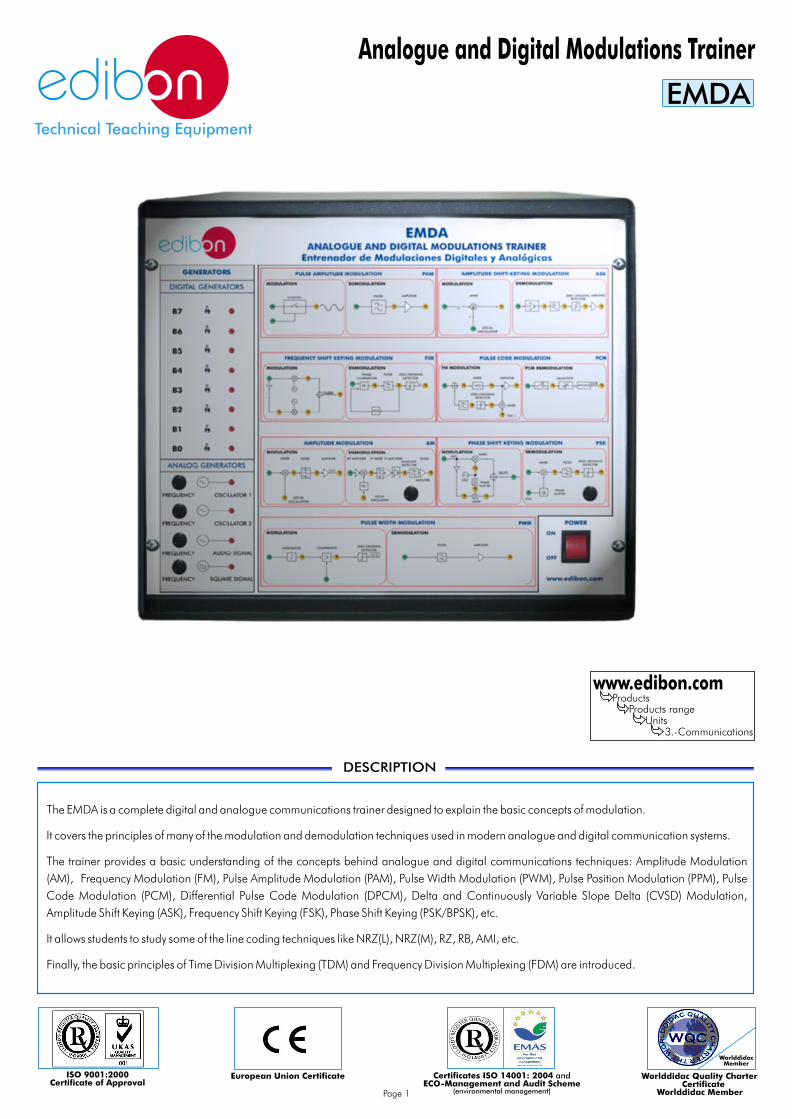
Analogue and Digital Modulations Trainer
EMDA
DESCRIPTION
www.edibon.comProducts
Products rangeUnits
3.-Communications
The EMDA is a complete digital and analogue communications trainer designed to explain the basic concepts of modulation.
It covers the principles of many of the modulation and demodulation techniques used in modern analogue and digital communication systems.
The trainer provides a basic understanding of the concepts behind analogue and digital communications techniques: Amplitude Modulation
(AM), Frequency Modulation (FM), Pulse Amplitude Modulation (PAM), Pulse Width Modulation (PWM), Pulse Position Modulation (PPM), Pulse
Code Modulation (PCM), Differential Pulse Code Modulation (DPCM), Delta and Continuously Variable Slope Delta (CVSD) Modulation,
Amplitude Shift Keying (ASK), Frequency Shift Keying (FSK), Phase Shift Keying (PSK/BPSK), etc.
It allows students to study some of the line coding techniques like NRZ(L), NRZ(M), RZ, RB, AMI, etc.
Finally, the basic principles of Time Division Multiplexing (TDM) and Frequency Division Multiplexing (FDM) are introduced.

Metallic box. Frequency Modulation (FM):
Power Supply. Mixer circuits.
Block diagram. Phase-Lock Loop circuit.
Carrier signal Generators Circuits. Voltage Controlled Oscillator circuit.
Audio signal Generator Circuit. Phase Comparator circuit.
Digital Generator and Line Coding Circuits: Filter and Amplifier circuits.
Non Return to Zero Level line coding circuit (NRZL). Time Division Multiplexing (TDM):
Non Return to Zero Mark line coding circuit (NRZM). Sample and Hold circuits.
Biphase Manchester line coding circuit. Synchronization circuits.
Biphase Mark circuit line coding circuit. Multiplexing circuits.
Return to Zero line coding circuit (RZ). Filter and Amplifier circuits.
Return to Bias line coding circuit (RB). Frequency Division Multiplexing (FDM):
Alternate Mark Inversion line coding circuit (AMI). Mixer circuits.
Pulse Amplitude Modem (PAM): Band-Pass Filters.
Sample & Hold circuit. Filters and Amplifier circuits.
Filter and Amplifier circuits. Cables and Accessories, for normal operation.
Pulse Width Modem (PWM): Manuals:
Sawtooth Generator circuit. This unit is supplied with the following manuals: Required Services, Assembly and Installation, Starting-up, Safety, Mixer circuit.Maintenance & Practices Manuals.
Filter and Amplifier circuits.
Pulse-Position Modulation Modem ( PPM):
Mixer circuit.
Filter and Amplifier circuits.
Amplitude-Shift Keying (M-ASK):
Mixer circuit.
Zero-Crossing circuit.
Filter and Amplifier circuits.
Frequency-Shift Keying (FSK):
Mixer circuits.
Phase-Lock Loop circuit.
Voltage Controlled Oscillator circuit.
Phase Comparator circuit.
Phase-Shift Keying (PSK):
Binary Phase Shift Keying modulator circuit (BPSK).
Quadrate Phase Shift Keying modulator circuit (QPSK).
Differential Phase Shift Keying modulator circuit (DPSK).
Mixer circuits.
Phase-Lock Loop circuit.
Voltage Controlled Oscillator circuit.
Phase Comparator circuit.
Filter and Amplifier circuits.
Amplitude Modulation (AM):
AM modulator circuit (AM).
Single Side Band Suppressed Carrier AM modulator circuit (SSBSC).
Double Side Band Suppressed Carrier modulator circuit (DSBSC).
Quadrate Amplitude modulator circuit (QAM).
Radio- Frequency Tuning circuit.
Intermediate-Frequency Mixer circuit.
Intermediate-Frequency Amplifier circuit.
Envelope detector circuit.
Product Detector circuit.
Filter and Amplifier circuits.
SPECIFICATIONS
www.edibon.comPage 2
Page 3 www.edibon.com
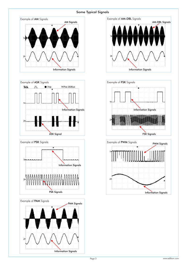
Example of AM Signals
Example of SignalsASK
Example of PWM SignalsExample of PSK Signals
AM Signals
Information Signals
Example of AM-DBL SignalsAM-DBL Signals
Information Signals
ASK Signal
Information Signals
Example of SignalsFSK
Information Signals
FSK Signals
PSK Signals
Information Signals
Information Signals
PWM Signals
Information Signals
Example of PAM SignalsPAM Signals
Some Typical Signals

1.- Study of the data coding techniques : NRZ(L), NRZ(M) RZ, RB, 13.- Introduction to the basic concept of the superheterodyne Biphase Mark, AMI. receiver.
2.- Study of basic principles of ASK modulation and demodulation 14.- Introduction to the QAM modulation.technique.
15.-Study of basic principles of FM modulation and demodulation 3.- Study of the spectrum of an ASK signal. technique.
4.- Study of a 4-ASK signal. 16.- Introduction to the PLL operation.
5.- Study of basic principles of FSK modulation and demodulation 17.- Introduction to the principle of TDM .technique.
18.- Introduction to the principle of FDM.6.- Study of the spectrum of an FSK signal.
19.-Study of Modems.7.- Advantages and disadvantages of ASK and FSK signals.
20.-Bit error measurements.8.- Basic principles of PWM and PPM modulation and
21.-Evaluation of the effects of noise on the transmission of digital demodulation.
signals.9.- Study of basic principles of PSK modulation and demodulation
technique.
10.-Study of PSK and QPSK variants of PSK modulation.
11.-Study of basic principles of AM modulation and demodulation technique.
12.-Comparison of the spectrum of AM, SSBSC, DSBSC signals.
EXERCISES AND PRACTICAL POSSIBILITIES
Some Practical Possibilities of the Unit:
REQUIRED SERVICES
DIMENSIONS & WEIGHTS
- Dimensions: 490 x 450 x 470 mm. approx.
- Weight: 40 Kg. approx.
- Electrical supply: single-phase, 220V./50Hz or 110V./60Hz.
www.edibon.comPage 4
Examples of the Software screens
www.edibon.com
Instructor Software
Trainer
StudentSoftware
+
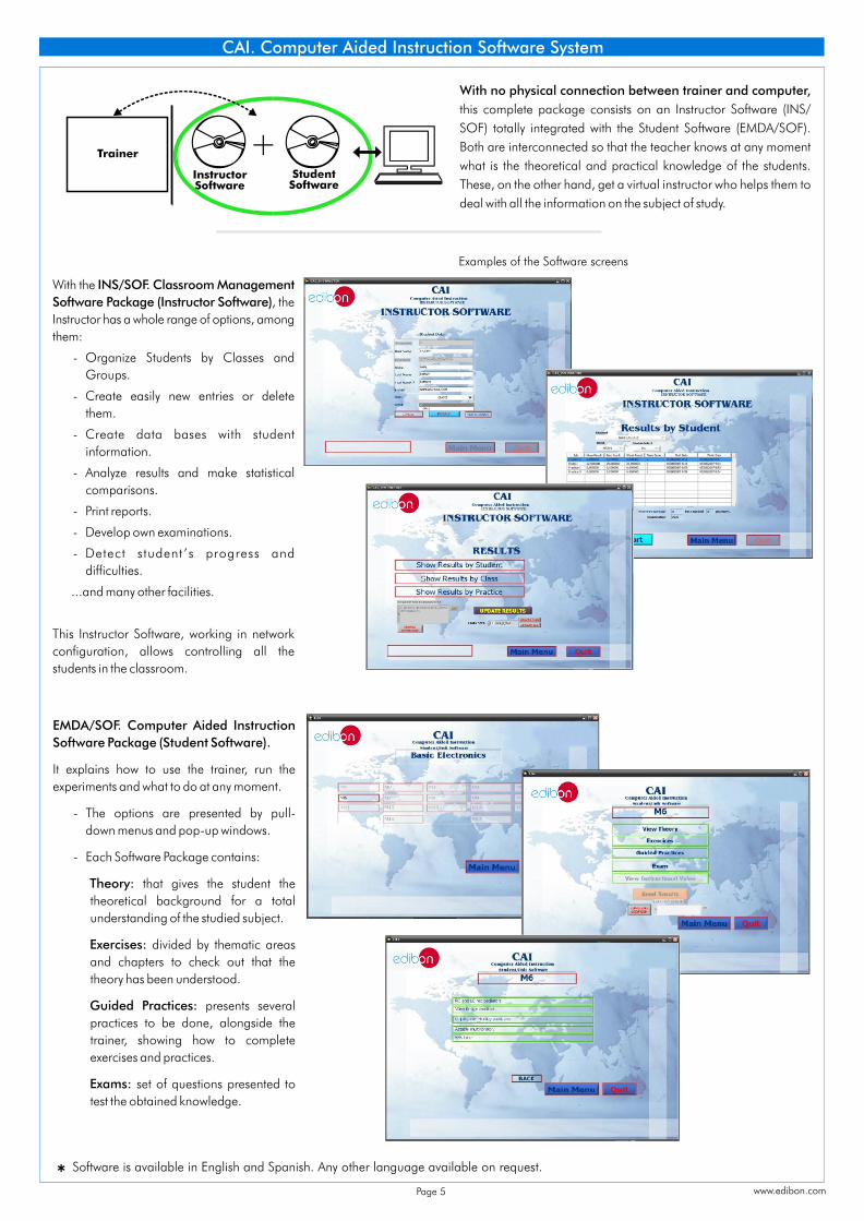
With no physical connection between trainer and computer,
this complete package consists on an Instructor Software (INS/
SOF) totally integrated with the Student Software (EMDA/SOF).
Both are interconnected so that the teacher knows at any moment
what is the theoretical and practical knowledge of the students.
These, on the other hand, get a virtual instructor who helps them to
deal with all the information on the subject of study.
With the INS/SOF. Classroom Management
Software Package (Instructor Software), the
Instructor has a whole range of options, among
them:
- Organize Students by Classes and
Groups.
- Create easily new entries or delete
them.
- Create data bases with student
information.
- Analyze results and make statistical
comparisons.
- Print reports.
- Develop own examinations.
- Detect student ’s progress and
difficulties.
...and many other facilities.
This Instructor Software, working in network
configuration, allows controlling all the
students in the classroom.
EMDA/SOF. Computer Aided Instruction
Software Package (Student Software).
It explains how to use the trainer, run the
experiments and what to do at any moment.
- The options are presented by pull-
down menus and pop-up windows.
- Each Software Package contains:
Theory: that gives the student the
theoretical background for a total
understanding of the studied subject.
Exercises: divided by thematic areas
and chapters to check out that the
theory has been understood.
Guided Practices: presents several
practices to be done, alongside the
trainer, showing how to complete
exercises and practices.
Exams: set of questions presented to
test the obtained knowledge.
Software is available * in English and Spanish. Any other language available on request.
CAI. Computer Aided Instruction Software System
Page 5
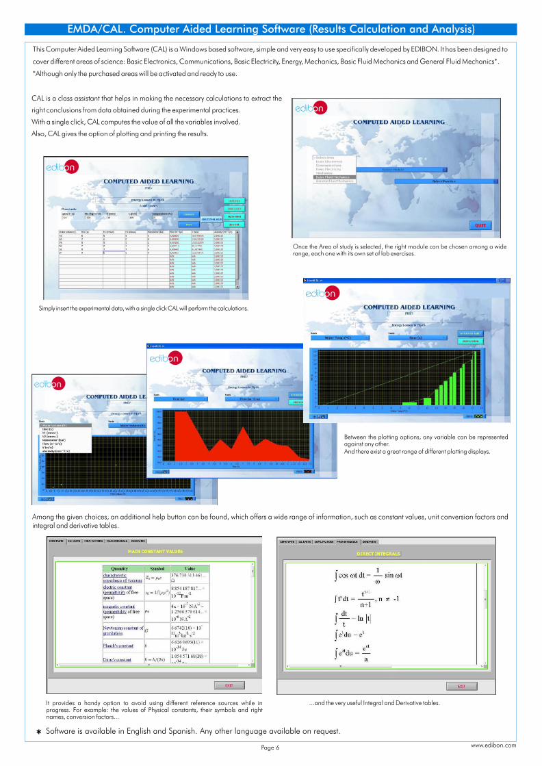
EMDA/CAL. Computer Aided Learning Software (Results Calculation and Analysis)
CAL is a class assistant that helps in making the necessary calculations to extract the
right conclusions from data obtained during the experimental practices.
With a single click, CAL computes the value of all the variables involved.
Also, CAL gives the option of plotting and printing the results.
Among the given choices, an additional help button can be found, which offers a wide range of information, such as constant values, unit conversion factors and integral and derivative tables.
Simply insert the experimental data, with a single click CAL will perform the calculations.
Between the plotting options, any variable can be represented against any other.And there exist a great range of different plotting displays.
Once the Area of study is selected, the right module can be chosen among a wide range, each one with its own set of lab exercises.
...and the very useful Integral and Derivative tables.It provides a handy option to avoid using different reference sources while in progress. For example: the values of Physical constants, their symbols and right names, conversion factors...
This Computer Aided Learning Software (CAL) is a Windows based software, simple and very easy to use specifically developed by EDIBON. It has been designed to
cover different areas of science: Basic Electronics, Communications, Basic Electricity, Energy, Mechanics, Basic Fluid Mechanics and General Fluid Mechanics*.
*Although only the purchased areas will be activated and ready to use.
www.edibon.com
Software is available * in English and Spanish. Any other language available on request.
Page 6

EDAS/VIS is the perfect link between the trainer and the PC. With the EDAS/VIS system, information from the trainer is sent to the computer. There, it can be analyzed and represented.We easily connect the Data Acquisition Interface Box (DAIB) to trainer with the supplied cables (connection points are placed in the trainer). Like any other hardware, the DAIB is connected to the PC through the Data Acquisition Board (DAB), and by using the Data acquisition and Virtual Instrumentation Software, the student can get the results from the undertaken experiment/practice, see them on the screen and work with them.
EDAS/VIS. EDIBON Data Acquisition System/Virtual Instrumentation System
Connectionpoints
Trainer
Studentpost
Data acquisition and virtual
instrumentationsoftware
1
2
34
“n”
Cables tointerface
Data acquisitioninterface box
Data
acq
uis
ition
board
Cable to
computer
5.1.2) DAB. Data Acquisition Board: For EDAS/VIS 1.25 Version:
PCI Data acquisition board (National Instruments) to be placed in a computer slot. Bus PCI.Analog input: Number of channels= 16 single-ended or 8 differential. Resolution=16 bits, 1 in
65536. Sampling rate up to: 1,250,000 S/s (samples per second). Input range (V)= 10V. Data transfers=DMA, interrupts, programmed I/0. DMA channels=6.
Analog output:Number channels=2. Resolution=16 bits, 1 in 65536. Max. output rate up to: 833KS/s. Output range(V)= 10V. Data transfers=DMA, interrupts, programmed I/0.
Digital Input/Output:Numbers of channels=24 inputs/outputs. Port 0 up to 8 Mhz.Timing: Counter/timers=2. Resolution: Counter/timers: 32 bits.For EDAS/VIS 0.25 Version:
Sampling rate up to: 250,000 S/s (samples per second).Analog output: Max. output rate up to:10 KS/s.Digital Input/Output: Number of channels=24 inputs/outputs. Port 0 up to 1 Mhz.Rest of characteristics are the same than EDAS/VIS 1.25 Version.
5.1)Hardware:5.1.1) DAIB. Data Acquisition Interface Box:
Metallic box. Dimensions: 310 x 220 x 145 mm. approx.Front panel:
16 Analog inputs (1 block with 12 voltage channels and 1 block with 2 current channels (4 connections)).
Sampling velocity 1,250,000 samples per second for EDAS/VIS 1.25 Version.Sampling velocity 250,000 samples per second for EDAS/VIS 0.25 Version.
2 Analog outputs.24 Digital inputs/outputs, configurable as inputs or outputs, with 24 state led indicators. These digital inputs/outputs are grouped in three ports of eight channels (P0, P1 and P3). 4 Digital signal switches 0-5V. 2 Analog signal potentiometers 12V.Main ON/OFF switch.
Inside: Internal power supply of 12 and 5 V. Potentiometer.Back panel: Power supply connector. SCSI connector (for data acquisition board).Connecting cables.
5.2)EDAS/VIS-SOF. Data Acquisition and Virtual Instrumentation Software:Compatible with actual Windows operating systems. Amicable graphical frame. Configurable software allowing the temporal/frequency representation of the different inputs and outputs. Visualization of a voltage of the circuits on the computer screen. It allows data store in a file, print screens and reports of the signals at any time.
Two independent signal generators, for sinusoidal, triangular, saw tooth and square.
Manuals:This system is supplied with the following manuals: Required Services, Assembly and Installation, Interface and Software, Starting-up, Safety, Maintenance & Practices Manuals.
Measurement, analysis, visualization, representation and report of results.Set of Virtual Instruments:
- Oscilloscope:Channels: 12 simultaneous. Maximum input voltage: 10V.All 12 input channels could be scaled to compare signal with different voltage levels.“Math Menu” with operations as Addition, Subtraction, Multiplication and Division, between any of the 12 oscilloscope channels.
- Function Generator:
Channels: 2 (allowing working simultaneously). Maximum output voltage: 10V.It includes a graph where an output signal for each channel is shown.
- Spectrum Analyzer:Channels: 12 (simultaneous). Max. voltage: 10V. Spectrum analyzer: based on the FFT.
- Multimeter:Voltmeter (Channels: 12 (simultaneous). Max. voltage: 10V RMS).Ammeter (Channels: 2 (simultaneous). Max. Ampere: 500 mA rms per channel).
- Transient Analyzer.- Logic Analyzer:
Number of Input channels: 8. TTL Voltage Level. Clock Source: 3 different sources.This instrument allows receiving as far as 8 digital signal simultaneously at 1 or 8 Mbps (depending the version).
- Logic Generator:Number of transmission channels: 8. TTL voltage level.This instrument allows generating up to 8 digital simultaneous signals of 1 or 8 Mbps (depending of the version).
Sampling velocity 1,250,000 samples per second for EDAS/VIS 1.25 Version.Sampling velocity 250,000 samples per second for EDAS/VIS 0.25 Version.
Only one EDAS/VIS is needed for all basic electronic boards. One EDAS/VIS is needed for each student work post.The EDAS/VIS allows to work with several basic electronic boards simultaneously.
This EDAS/VIS System includes DAIB + DAB + EDAS/VIS-SOF:
Important!
DAIB
DAB
Software available * in English and Spanish. Any other language available on request.
EDAS/VIS-SOF
±
±
±
±
±
±
±
www.edibon.com/products/catalogues/en/units/communications/digital/EDAS-VIS.pdfNote: for more information see EDAS/VIS specific Catalogue:
Page 7 www.edibon.com
Page 8
*Specifications subject to change without previous notice, due to the convenience of improvements of the product.
REPRESENTATIVE:
C/ Del Agua, 14. Polígono Industrial San José de Valderas.28918 LEGANÉS. (Madrid). SPAIN.Phone: 34-91-6199363 FAX: 34-91-6198647E-mail: [email protected] WEB site: www.edibon.com
Issue: ED01/10Date: May/2010
COMPLEMENTS
CAI. Computer Aided Instruction Software System.
EMDA/CAL. Computer Aided Learning Software (Results Calculation and Analysis).
EDAS/VIS. EDIBON Data Acquisition System/Virtual Instrumentation System.