analysis and compensation about temperature influence to
TRANSCRIPT

Analysis and Compensation About Temperature Influence to Optical-Fiber Gyro
Zero Bias
Zhou Haiyuan, Yang Heng, Wang Qianxue, Liu Xinming and Pan Liang
China Satellite Maritime Tracking & Controlling Department
Jiangyin, 214431, China
e-mail: [email protected]
Abstract—Compared to other gyro the dynamic performance
of optical-fiber gyro was better and the price was cheap.
Optical-fiber gyro was suitable to build SINS. By the way, zero
bias of optical-fiber gyro was sensitive to temperature, and the
compensation technique was a hot point in INS research.
According to the above situation, based on one type optical-
fiber gyro, the influence mechanism about temperature to
optical-fiber gyro zero bias was studied, and a test method was
designed, were analysed, finally based on multinomial
simulation a compensation math model was established, and
the research result discovered that temperature was a big
influence to optical-fiber gyro zero bias, and it can be fixed by
a compensation math model based on multinomial simulation.
Keywords-Multinomial Simulation; Gyro Zero Bias;
Temperature Characteristic; Temperature Compensation;
Temperature Sensor
I. INTRODUCTION
Gyro was the core component of inertial navigation equipment, and it was the key factor to determine the position and attitude accuracy of inertial navigation equipment. At present, the traditional liquid lifting gyro has entered the technical stability period, the accuracy has been difficult to break through; laser gyro technology has also been basically mature, and entered the stage of engineering application. Compared with the liquid lifting gyro, optical fiber gyro has the advantages of simple structure, fast starting, long service life, small volume and so on; Compared with the laser gyro, with lower price and higher dynamic performance, optical-fiber gyro was more suitable for construction of strap down inertial system.
The temperature was main factors affecting the performance of optical-fiber gyro[1-4], the temperature change will lead to deviation from the original state of the optical-fiber gyro because of its optical element temperature sensitive character, which affects the output accuracy of the system, so the compensation about optical-fiber gyro zero bias caused by temperature change was most important problem to be solved to inertial navigation equipment based on optical-fiber gyro.
II. INFLUENCE OF TEMPERATURE ON ZERO BIAS OF
OPTICAL-FIBER GYRO
A. Experimental design
The optical-fiber gyro used in this experiment was a kind of advanced high precision, which requires the gyro performance index: zero bias stability was better than 0.02º/h, and the scale factor stability was better than 10ppm.
Test hardware conditions include temperature control turntable and supporting facilities, the specific configuration was as follows:
1) Temperature control turntable The temperature range was between -20℃ and +60℃;
the output range was 0.01º/s to 1000º/s; the rate stability was
1×10⁻⁴; the temperature stability was ±0.5℃.
2) Matching test facilities The vibration isolation foundation avoids the interference
of external vibration to the test. The data acquisition device was used for the acquisition of gyro data, and the turntable control computer was used for the control of turntable and the collection of gyro data.
Fig.1 was a connection diagram of temperature experimental equipment. The 2 temperature sensors were located at the top and the side of the gyro shell for recording the ambient temperature. After the gyro was started, the output of the gyro and the temperature of the temperature sensor were collected, and the sampling frequency was sampled 1 times per second.
testing turntables
fiber optic gyro
data acquisition
and processing
system
computer
temperature
output signal
Control signal
sensor 1sensor 2
Figure 1. Equipment connection about temperature test
B. Test result
In order to test the temperature characteristics of the optical-fiber gyro, a total of 8 fixed temperature gyro zero bias tests were arranged according to the experimental scheme. 4 experiments were conducted at each fixed
2nd International Conference on Sensor Network and Computer Engineering (ICSNCE 2018)
Copyright © 2018, the Authors. Published by Atlantis Press. This is an open access article under the CC BY-NC license (http://creativecommons.org/licenses/by-nc/4.0/).
Advances in Computer Science Research, volume 79
11
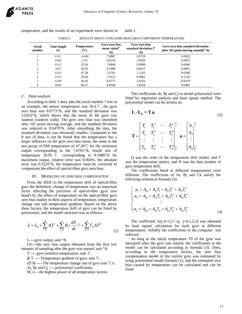
temperature, and the results of an experiment were shown in table 1.
TABLE I. RESULTS ABOUT GYRO ZERO BIAS ABOUT DIFFERENT TEMPERATURE
Serial
number
Time length
(s)
Temperature
(℃)
Gyro zero bias
mean value(º/h)
Gyro zero bias
standard deviation (º/h)
Gyro zero bias standard deviation
after 101 point moving smooth(º/h)
1 6161 -14.60 7.6967 0.9728 0.0433
2 8569 2.70 8.0374 1.0503 0.0475
3 8161 22.93 7.6844 0.9948 0.0640
4 4051 39.95 8.1986 0.6017 0.0893
5 8443 47.28 7.6761 1.1103 0.0268
6 9194 50.83 7.9121 0.9801 0.1145
7 8109 56.43 8.0771 1.0352 0.0479
8 8006 60.27 8.0594 1.0534 0.0495
C. Data analysis
According to table 1 data, take the serial number 7 test as
an example, the sensor temperature was 56.4℃, the gyro
zero bias was 8.0771º/h, and the standard deviation was 1.0352º/h, which shows that the noise of the gyro was random (random walk). The gyro zero bias was smoothed after 101 point moving average, and the standard deviation was reduced to 0.0479º/h. After smoothing the data, the standard deviation was obviously smaller. Compared to the 8 sets of data, it can be found that the temperature has a larger influence on the gyro zero bias mean, the same to the
test group of fifth temperature of 47.28℃ for the minimum
output corresponding to the 7.6761º/h, fourth sets of
temperature 39.95 ℃ corresponding to 8.1986º/h for
maximum output, relative error was 0.064%, the absolute error was 0.5225º/h, the temperature must be corrected to compensate the effect of optical-fiber gyro zero bias.
III. MODELING OF ZERO BIAS COMPENSATION
From the IEEE to the temperature drift of optical-fiber gyro the definition: change of temperature was an important factor affecting the precision of optical-fiber gyro zero bias[5-6], the effect of temperature on the optical-fiber gyro zero bias mainly in three aspects of temperature, temperature change rate and temperature gradient. Based on the above three factors, the temperature drift of gyro can be fitted by polynomial, and the model structure was as follows:
0
1 1 1
( )
qm n
i j k
i j k
i j k
dTL L AT B C T
dt (1)
L----gyro output, unit º/h. L0----the zero bias output obtained from the first two
minutes of sampling after the gyro was started, unit º/h.
T ---- gyro sensitive temperature, unit ℃.
Δ T ---- Temperature gradient of gyro, unit ℃.
dT/dt ---- The temperature change rate of gyro unit ℃/s.
Ai, Bj and Cj ---- polynomial coefficients, M, n -- the highest power of all temperature factors.
The coefficients Ai, Bj and Cj in model polynomial were fitted by regression analysis and least square method. The polynomial model can be written as:
0L - L = T a
(2)
2
1 1 1
2
2 2 2
2
q
q
q
N N N
T T T
T T T
T T T
T
1
2
q
a
a
a
a
Q was the order of the temperature drift model, and T
was the temperature matrix, and N was the data number of gyro temperature drift.
The coefficients fitted at different temperatures were different. The coefficients of Ai, Bj and Ck satisfy the following relation in formula (3):
2 3
1 10 11 1 12 1 13 1
2 3
2 20 21 2 22 2 23 2
2 3
0 1 2 3
q q q q q q q q
a A A T A T A T
a A A T A T A T
a A A T A T A T (3)
The coefficient Aij (i=1,2…q;j=0,1,2,3) was obtained
by least square calculation for each gyro at different temperatures. Solidify the coefficients in the computer test software.
As long as the initial temperature T0 of the gyro was measured after the gyro was started, the coefficients in the model can be calculated according to formula (3). Then, according to the temperature factors, the zero bias compensation model of the current gyro was estimated by using polynomial model formula (1), and the estimated zero bias caused by temperature can be calculated and can be fixed.
Advances in Computer Science Research, volume 79
12

IV. OPTICAL-FIBER GYRO ZERO BIAS CHARACTERISTICS
COMPENSATION RESULT
The influence of temperature on zero bias was mainly shown in three aspects: temperature, temperature change rate and temperature gradient[7-8]. For a comprehensive analysis of the temperature character of zero bias of optical-fiber gyro, effect of temperature, effect of temperature change rate and effect of temperature gradient were all compensated. The highest temperature compensation to 4 order, 1 order compensation for temperature gradient temperature change rate, 1 order compensation for temperature gradient.
A. Temperature affects compensation results
Using the data in Table 1, the polynomial of temperature on the zero bias of the gyro was fitted to each order curve, and the result was shown in figure 2. According to the fitting results, the gyro zero bias data was compensated for the
continuous change of temperature from -20℃ to 60℃ in Fig.
3, the 2 and 4 order compensation results were shown in figure 4. The comparison of the results of each order compensation was shown in table 2.
test result
Linear
1 order
2 order
3 order
4 order
5 order
gyro
out
put
erro
r
gyro temperature sensor 2 Figure 2. Polynomial fitting curve about the gyro zero bias caused by
temperature
gyro
outp
ut
afte
r sm
ooth
gyro
temperatu
re senso
r 2
Figure 3. The influence about temperature to gyro zero bias
gy
ro o
utp
ut
gy
ro te
mp
era
ture
sen
sor 2
orginal output after smooth
After 2 order compensation
temperature
gyro
outp
ut
gyro
tem
pera
ture
senso
r 2
orginal output after smooth
After 4 order compensation
temperature
Figure 4. Gyro output by 2\4order polynomial compensation while
temperature transition
TABLE II. GYRO OUTPUT BY 1 TO 4ORDER POLYNOMIAL
COMPENSATION WHILE TEMPERATURE TRANSITION
Compensation
method
Gyro zero bias
mean value(º/h)
Gyro zero bias
standard
deviation (º/h)
1 none 8.4747 0.3274
2 linear 8.4416 0.3007
3 2order 8.4834 0.2946
4 3order 8.3944 0.3050
5 4order 8.4843 0.3197
From table 2, it can be seen that the standard deviation of
gyro zero bias was smaller after compensation, and the two order polynomial compensation was the best.
B. Compensation result of temperature gradient change
The relationship between the temperature gradient and the gyro zero bias was shown in figure5.
gyro
outp
ut
temp
erature g
radien
t
gyro temperature sensor 2
gyro output
temperature gradient
Figure 5. Relationship between temperature gradient and gyro zero bias
Advances in Computer Science Research, volume 79
13

Based on temperature compensation, temperature gradient compensation was added on the zero bias, the zero bias standard deviation was shown in table 3.
TABLE III. THE RESULT AFTER ADDING COMPENSATION BY
TEMPERATURE GRADIENT
Compensation
method
Gyro zero bias
mean value(º/h)
Gyro zero bias
standard deviation
(º/h)
1 none 0.3274 --
2 Linear 0.3007 0.2357
3 2order 0.2946 0.2299
4 3order 0.3050 0.2436
5 4order 0.3197 0.2569
According to the date from table 3, on the same order
after adding the temperature gradient compensation the results was improved obviously, and two order polynomial compensation effect was the best, standard deviation was reduced to the original value of 2/3.
C. Compensation result of temperature change rate
In Figure 3, the difference between each point data and the average value can reflect the influence of the temperature change rate on the gyro zero bias to a certain extent. On the basis of considering the temperature and temperature gradient, the influence of temperature change rate on the gyro zero bias was also added. The 2 and 4 order fitting results were shown in fig 6. The comparison of the results of each order compensation was shown in table 4.
orginal data
2 order compensation
temperature gradient
temperature transition rate
gyro
outp
ut
orginal data
4 order compensation
temperature gradient
temperature transition rate
gyro
outp
ut
Figure 6. Gyro output by 2\4order polynomial compensation after
temperature transition\temperature gradient\temperature transition rate
TABLE IV. COMPENSATION RESULT AFTER TEMPERATURE
TRANSITION\TEMPERATURE GRADIENT\TEMPERATURE
TRANSITION RATE
Compensation
Method
Gyro zero bias
mean value(º/h)
Gyro zero bias
standard deviation
(º/h)
1 none 8.4747 0.3274
2 Linear 8.4747 0.1556
3 2order 8.4747 0.1269
4 3order 8.4747 0.1103
5 4order 8.4747 0.1017
From table 5 and Figure 4 can be seen through the “four
order polynomial + temperature difference + change rate of the temperature ”compensation effect was obvious, the gyro zero bias standard deviation can be reduced to 1/3 by the fitting," the compensation effect was obvious.
V. CONCLUSION
Temperature was one of the most important factors that affect the zero bias of optical-fiber gyro. The temperature characteristics about optical-fiber gyro has to be studied and zero bias caused by the temperature changes must be compensated if optical-fiber gyro can be used in the field of engineering application. Based on the analysis of the influence mechanism of optical-fiber gyros working principle and temperature influence to zero bias, temperature test of optical-fiber gyro was carried out, zero bias compensation method was studied, and the compensation effect was analyzed by experiment data. The experiment results show that the influence of temperature on the zero bias of optical-fiber gyro was effectively reduced by using multinomial fitting method, which were compensated by three aspects of temperature, temperature gradient and temperature change rate.
REFERENCES
[1] HAN Bin, LIN Yu-rong, DENG Zheng-long. Overview on modeling and compensation of FOG temperature drift[J]. Journal Chinese Inertial Technology, 2009, 17(2):218-224.
[2] Xu Hong-jie, Zhang Wen-yan, Xu Xiaobin,et al. Research on thermal induced Non-reciprocity in optical-fiber gyro with double optical length[J]. ACTA Photonica Sinica, 2014,43(10):1006001-1-5.
[3] Yu Xuhui, Ma Huilian, Jin Zhonghe, et al. Improving thermal stability of a resonator optical-fiber gyro employing a polarizing resonator[J]. Optics Express, 2013, 21(1):358-369.
[4] Lefèvre H C. The fiber-optic gyro: Achievement and perspective[J]. Gyroscopy and Navigation, 2012, 3(4):223-226.
[5] DUSAN Agrez. Improving Phase estimation with leakage minimization[J]. IEEE Trans on IM, 2005, 54(4): 1347-1353.
[6] LIU Yimg, XU Jin-tao, WANG Min-juan. Analyswas and compensation of the temperature field inside fiber optic coil[J]. Journal of Xi AN University of Posts and telecommunications, 2015,20(5):28-33.76-78
[7] LIU Jie-yu, YU Zhi-yong, MA Xue-wen. Modeling and compensation of static temperature error synthetically for optical-fiber gyro[J]. Acta Optica Sinica, 2012, 32(8): 201-205.
[8] ZHANG Yan-ping, PAN Zi-jun, WEI Zhi-wu, et al. Hardwwere implementation of temperature compensation for FOG’ s scale-factor[J]. Journal of Chinese Inertial Technology,2013,21(5):660-662.
Advances in Computer Science Research, volume 79
14