analysis and design for aluminum forging process a … · 2010-07-21 · analysis and design for...
TRANSCRIPT
ANALYSIS AND DESIGN FOR ALUMINUM FORGING PROCESS
A THESIS SUBMITTED TO THE GRADUATE SCHOOL OF NATURAL AND APPLIED SCIENCES
OF MIDDLE EAST TECHNICAL UNIVERSITY
BY
HÜSEYĐN ÖZTÜRK
IN PARTIAL FULFILLMENT OF THE REQUIREMENTS FOR
THE DEGREE OF MASTER OF SCIENCE IN
MECHANICAL ENGINEERING
DECEMBER 2008
Approval of the thesis:
ANALYSIS AND DESIGN FOR ALUMINUM FORGING PROCESS
submitted by HÜSEYĐN ÖZTÜRK in partial fulfillment of the requirements for the degree of Master of Science in Mechanical Engineering, Middle East Technical University by, Prof. Dr. Canan Özgen Dean, Graduate School of Natural and Applied Sciences __________________ Prof. Dr. Süha Oral Head of the Department, Mechanical Engineering __________________ Prof. Dr. Mustafa Đlhan Gökler Supervisor, Mechanical Engineering Dept., METU __________________ Prof. Dr. Haluk Darendeliler Co-Supervisor, Mechanical Engineering Dept., METU __________________ Examining Committee Members: Prof. Dr. R. Orhan Yıldırım Mechanical Engineering Dept., METU __________________ Prof. Dr. Mustafa Đlhan Gökler Mechanical Engineering Dept., METU __________________ Prof. Dr. Haluk Darendeliler Mechanical Engineering Dept., METU __________________ Prof. Dr. Haluk Aksel Mechanical Engineering Dept., METU __________________ (M.Sc.) Sertan Gülbahar Aydın Yazılım ve Elektronik Sanayii A.Ş. __________________ Date: December 16th, 2008

iii
I hereby declare that all information in this document has been obtained and presented in accordance with academic rules and ethical conduct. I also declare that, as required by these rules and conduct, I have fully cited and referenced all material and results that are not original to this work.
Name, Last name: Hüseyin Öztürk Signature:

iv
ABSTRACT
ANALYSIS AND DESIGN FOR ALUMINUM FORGING PROCESS
Öztürk, Hüseyin
M.Sc., Department of Mechanical Engineering
Supervisor: Prof. Dr. Mustafa Đlhan Gökler
Co-Supervisor: Prof. Dr. Haluk Darendeliler
December 2008, 167 pages
Aluminum forging products has been increasingly used in automotive and aerospace
industry due to their lightness and strength. In this study, aluminum forging
processes of a particular industrial part for the two different alloys (Al 7075 and
Al 6061) have been analyzed. The forging part, forging process and the required dies
have been designed according to the aluminum forging design parameters. The
proposed process has been simulated by using the Finite Volume Method. In the
simulations, analysis of the part during forging process has been performed; and the
required forging force, the temperature distribution and the effective stress
distribution in the parts have been obtained. The forging dies were produced in the
METU-BILTIR Center CAD/CAM Laboratory. The experimental study has been
performed in the METU-BILTIR Center Forging Research and Application
Laboratory. The parts were produced without any defects as obtained in the finite
volume simulations. The results of the experiment and finite volume simulation are
compared and it has been observed good agreement.
Keywords: Aluminum Forging, Aluminum Forging Design Parameters, Al 7075,
Al 6061, Finite Volume Method.

v
ÖZ
ALÜM ĐNYUM DÖVME PROSESĐNĐN ANAL ĐZĐ VE TASARIMI
Öztürk, Hüseyin
Yüksek Lisans, Makina Mühendisliği Bölümü
Tez Yöneticisi: Prof. Dr. Mustafa Đlhan Gökler
Ortak Tez Yöneticisi: Prof. Dr. Haluk Darendeliler
Aralık 2008, 167 sayfa
Alüminyum dövme parçalar hafifliği ve dayanıklılığından dolayı otomotiv, havacılık
ve uzay sanayinde artarak kullanılmaya başlanmıştır. Bu çalışmada, belirli bir
endüstriyel parçanın iki farklı alaşımda (Al 7075 ve Al 6061) alüminyum dövme
uygulamaları analiz edilmiştir. Dövme parça, dövme prosesi ve dövme kalıpları
alüminyum dövme tasarım parametrelerine göre tasarlanmıştır. Önerilen
uygulamanın Sonlu Hacim Metodu kullanılarak benzetimi yapılmıştır.
Benzetimlerde, parçanın dövme prosesi sırasındaki analizi gerçekleştirilmi ştir ve
gerekli olan dövme kuvveti, sıcaklık dağılımı ve parçadaki etkin gerilim dağılımı
elde edilmiştir. ODTÜ-BĐLTĐR Merkezi CAD/CAM Laboratuarında kalıpların
üretimi yapılmıştır. ODTÜ-BĐLTĐR Merkezi Dövme Araştırma ve Uygulama
Laboratuarında deneysel çalışma yapılmıştır. Parçalar sonlu hacim benzetimlerinde
elde edildiği gibi hatasız olarak üretilmiştir. Deneyin ve sonlu hacim benzetiminin
sonuçları karşılaştırılmış ve sonuçların tutarlı olduğu gözlemlenmiştir.
Anahtar Kelimeler: Alüminyum Dövme, Alüminyum Dövme Tasarım
Parametreleri, Al 7075, Al 6061, Sonlu Hacim Metodu.

vi
To My Family
vii
ACKNOWLEDGEMENTS
I express sincere appreciation to my supervisor Prof. Dr. Mustafa Đlhan Gökler and
my co-supervisor Prof. Dr. Haluk Darendeliler for their guidance, advice and insight
throughout the study.
The author was supported by “TÜBĐTAK-SANTEZ” scheme with the collaborations
of The Scientific and Technological Research Council of Turkey (TÜBĐTAK),
METU-BILTIR Research and Application Center of Middle East Technical
University (METU) and AKSAN Steel Forging Company.
I would like to thank to METU-BILTIR Research and Application Center,
TÜBĐTAK, AKSAN Steel Forging Company and METU Central Laboratory for the
research applications performed during the experimental study.
I also wish to thank to my senior colleagues Đlker Durukan, Kazım Arda Çelik,
Mehmet Maşat and Sevgi Saraç for their valuable support and assistance.
Special thanks go to my colleagues, Arda Özgen, Özgür Cavbozar, Ulaş Göçmen,
Cihat Özcan, Ali Murat Kayıran, Gökhan Biçer and Sinem Demirkaya for their
supports and encouragement.
Further, thanks go to Halit Şahin, Ali Demir, Hüseyin Ali Atmaca, Tarık Öden,
Osman Mumcu, Filiz Güngör Sütekin, Arzu Öztürk, Tuğba Karakurum, Turan
Kalender, Halime Küçük and Mehmet Ali Sarıhan for their endless efforts and aids.
I am deeply indebt to my parents, Hacer and Hüsamettin Öztürk, my sister Sultan
Aytemiz, her husband Emre Aytemiz and my niece Öykü Aytemiz for their
encouragement and faith in me.
viii
TABLE OF CONTENTS
ABSTRACT ........................................................................................................... iv
ÖZ ............................................................................................................................v
ACKNOWLEDGEMENTS ................................................................................... vii
TABLE OF CONTENTS...................................................................................... viii
LIST OF TABLES................................................................................................. xii
LIST OF FIGURES ................................................................................................xv
LIST OF SYMBOLS ........................................................................................... xxii
CHAPTERS
1. INTRODUCTION ................................................................................................1
1.1 Classification of Forging .................................................................................2
1.1.1 Classification of Forging According to Type of Die Set............................2
1.1.2 Classification of Forging According to Temperature.................................4
1.1.3 Classification of Forging According to Type of Machine..........................4
1.1.4 Classification of Forging According to the Billet Material ........................5
1.2 Basic Design Considerations of Forging Process .............................................5
1.3 Computer Aided Design (CAD), Computer Aided Manufacturing (CAM)
Applications and Computer Aided Engineering (CAE) in Forging Process............6
1.4 Previous Studies..............................................................................................8
1.5 Scope of the Thesis .......................................................................................10
2. ALUMINUM FORGING....................................................................................12
ix
2.1 Introduction...................................................................................................12
2.2 Aluminum Alloys..........................................................................................13
2.3 Forgeability of Aluminum Alloys..................................................................15
2.4 Forging Temperature for Aluminum..............................................................17
2.5 Forging Equipment Used for Aluminum Forging ..........................................20
2.6 Die Materials and Die Temperature in Aluminum Forging ............................21
2.7 Heating Equipment Used for Aluminum Forging...........................................23
2.8 Lubrication in Aluminum Forging.................................................................23
2.9 Trimming in Aluminum Forging ...................................................................24
2.10 Heat Treatment of Forged Aluminum Parts .................................................25
3. DESIGN PARAMETERS OF ALUMINUM FORGING PROCESS...................26
3.1 Part Design....................................................................................................26
3.2 Shape and Size Factors in Forging.................................................................32
3.3. Flash Geometry ............................................................................................32
3.4 Upsetting and Preform Design.......................................................................34
4. DESIGN OF ALUMINUM FORGING AND FINITE VOLUME ANALYSIS OF
ALUMINUM FORGING PROCESS......................................................................38
4.1 Case Study for Aluminum Forging Process ...................................................38
4.2 3-D Modeling of Forging Part .......................................................................39
4.3 Aluminum Forging Die Design .....................................................................41
4.4 Simulation Process Parameters for Finite Volume Method ............................45
4.4.1 Defining the Process Type, Importing Forging Dies and Modeling of
Billet...................................................................................................................46
4.4.2 Assigning the Material Properties of Dies and Billet...............................47
4.4.3 Initial Temperature of Billet and Dies.....................................................50

x
4.4.4 Defining the Coefficient of Friction........................................................50
4.4.5 Defining the Press in Finite Volume Program.........................................50
4.4.6 Defining Forming Properties ..................................................................51
4.5 Analysis of Aluminum Forging Process by Finite Volume Method ...............52
4.5.1 Single Stage Forging Operation..............................................................52
4.5.2 Two Stages Forging Operation ...............................................................56
4.5.3 Simulation Results..................................................................................62
5. MANUFACTURING OF THE FORGING DIES AND EXPERIMENTS OF
ALUMINUM FORGING PROCESS......................................................................76
5.1 Manufacturing of the Forging Dies................................................................76
5.2 Preparation for the Experiments ....................................................................80
5.3 Experimentation of the Aluminum Forging Process.......................................84
5.4 Results for the Experiment ............................................................................90
5.5 Discussion of the Results...............................................................................95
5.6 Effect of Forging Temperature on the Part.....................................................97
6. FINITE VOLUME SIMULATIONS AND EXPERIMENTS OF ALUMINUM
ALLOY 6061 .......................................................................................................101
6.1 Introduction.................................................................................................101
6.2 Finite Volume Simulation of Aluminum Alloy 6061...................................101
6.2.1 Simulation Results of Aluminum Alloy 6061 for the Particular Part .....104
6.3 Experiments of Aluminum Alloy 6061........................................................127
7. CONCLUSIONS ..............................................................................................136
7.1 Discussion of the Results.............................................................................136
7.2 Future Works ..............................................................................................139
REFERENCES.....................................................................................................140
xi
APPENDICES
A. TECHNICAL DRAWING OF THE FORGING PART....................................145
B. TECHNICAL INFORMATION OF 10 MN (1000 TON) SMERAL
MECHANICAL PRESS .......................................................................................147
C. TECHNICAL DRAWING OF THE FORGING DIES .....................................149
D. MATERIAL PROPERTIES OF DIEVAR AND HEAT TREATMENT
PROCESS ............................................................................................................153
D.1 Material Properties of Dievar......................................................................153
D.2 Heat Treatment Process ..............................................................................155
E. TECHNICAL INFORMATION OF THE COLORLESS WATER SOLUBLE
LUBRICANT .......................................................................................................160
F. EXPERIMENTAL DATA OF ALUMINUM ALLOY 7075-0 FOR THE BILLET
TEMPERATURES OF 350 oC, 300 oC, 250 oC AND 200 oC................................161
xii
LIST OF TABLES
TABLES
Table 2.1 Aluminum Forging Alloys and Their Compositions.................................14
Table 2.2 Aluminum Alloy Groups and Their Major Alloying Elements.................15
Table 2.3 Recommended Forging Temperature Ranges for Aluminum Alloys ........19
Table 2.4 Forging Performance of Forging Presses and Hammers for Several
Aluminum Alloys ...................................................................................................20
Table 2.5 Die Temperature Ranges for Different Forging Equipment......................22
Table 3.1 Recommended Machining Allowances....................................................26
Table 3.2 Recommended Draft Angles....................................................................29
Table 3.3 Recommended Corner and Fillet Radii on Part ........................................30
Table 3.4 Flash Thicknesses for Different Materials According to Plan Area at the
Trim Line ...............................................................................................................34
Table 3.5 Dimensions in Preform for Aluminum Forging........................................37
Table 4.1 Billet Geometry and Billet Dimension.....................................................47
Table 4.2 Flow Stress Parameters for 7075-0 ..........................................................48
Table 4.3 Material Properties of 7075-0 ..................................................................49
Table 4.4 Properties of Crank Press available in METU-BILTIR Center .................51
Table 4.5 Forming Properties in Finite Volume Analysis ........................................51
Table 4.6 Maximum Die Force and Effective Stress for Different Forging
Temperatures of Al 7075 ........................................................................................63

xiii
Table 4.7 Maximum Part Temperatures for Different Forging Temperatures of Al
7075 .......................................................................................................................63
Table 5.1 Billet Dimensions and Billet Weights ......................................................82
Table 5.2 Experimental Data Recorded during Forging Process ..............................91
Table 5.3 Experimental Data Measured after the Forging Process ...........................93
Table 6.1 Flow Stress Parameters for 6061-0 ........................................................102
Table 6.2 Material Properties of 6061-0 ................................................................103
Table 6.3 Maximum Die Force and Effective Stress for Different Forging
Temperatures of Al 6061 ......................................................................................125
Table 6.4 Maximum Part Temperatures for Different Forging Temperatures of Al
6061 .....................................................................................................................125
Table 6.5 Comparison of the Finite Volume Simulation Results of Al 6061 and Al
7075 for 400 oC ....................................................................................................126
Table 6.6 Billet Dimensions and Billet Weights of the Aluminum Alloy 6061 for
Different Temperatures.........................................................................................130
Table 6.7 Experimental Data Recorded during Forging Process for the Aluminum
Alloy 6061 for Different Temperatures .................................................................132
Table 6.8 Experimental Data for Forging of Aluminum Alloy 6061 ......................134
Table D.1 Chemical Composition of Dievar (%)...................................................153
Table D.2 Physical Properties of Dievar................................................................154
Table D.3 Mechanical Properties of Dievar at Room Temperature for Different
Hardness Values ...................................................................................................154
Table D.4 Hardness Values of the Tool Steel for Hot Aluminum Forging .............155
Table D.5 Hardness Values of the Upsetting Dies .................................................156
Table D.6 Hardness Values of the Upper Finish Die .............................................156
Table D.7 Hardness Values of the Lower Finish Die .............................................157

xiv
Table F.1 Billet Dimensions and Billet Weights of the Aluminum Alloy 7075 for
Different Temperatures.........................................................................................162
Table F.2 Experimental Data Recorded after the Forging Process for Aluminum
Alloy 7075............................................................................................................164
xv
LIST OF FIGURES
FIGURES
Figure 1.1 Illustration of Open Die Forging Process..................................................3
Figure 1.2 Illustration of Closed Die Forging Process ...............................................3
Figure 1.3 Design Parameters of Forged Part ............................................................6
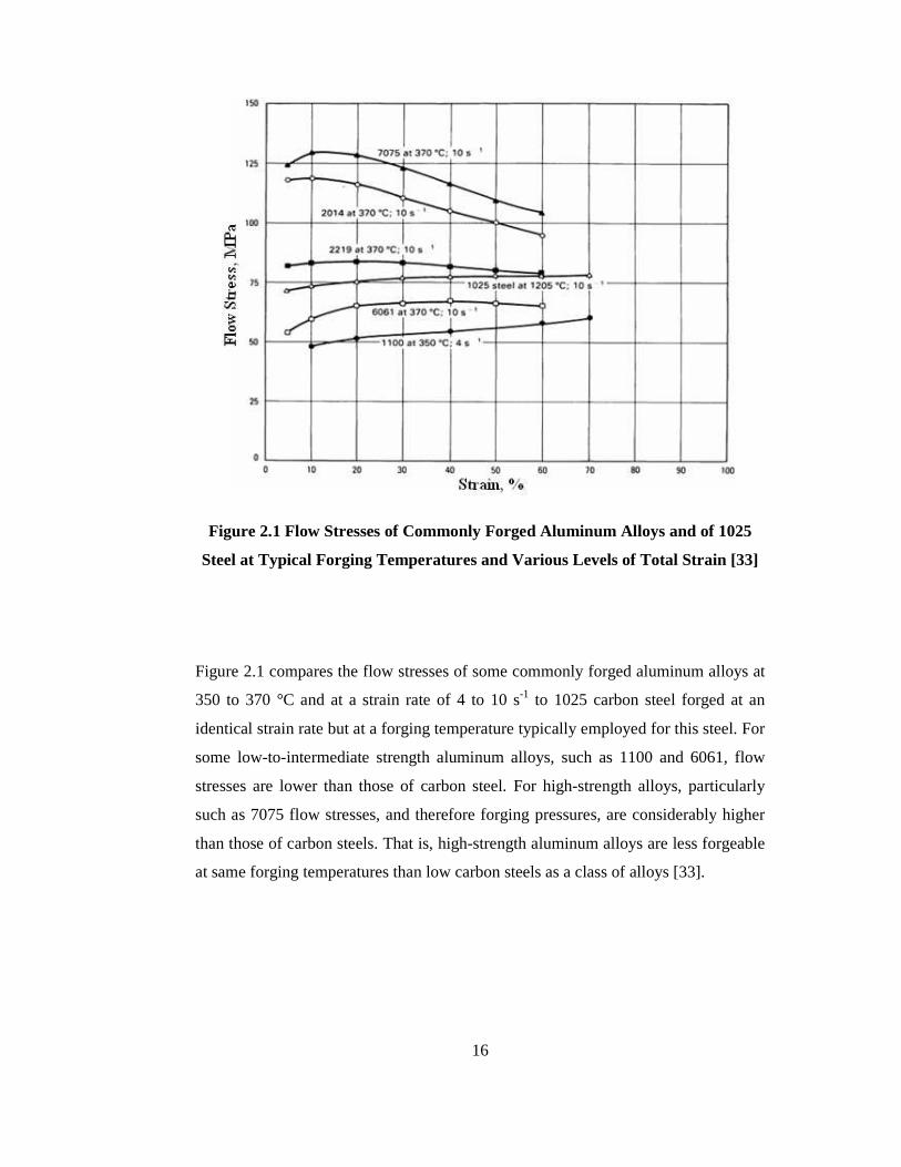
Figure 2.1 Flow Stresses of Commonly Forged Aluminum Alloys and of 1025 Steel
at Typical Forging Temperatures and Various Levels of Total Strain ......................16
Figure 2.2 Forgeability and Forging Temperatures of Various Aluminum Alloys...18
Figure 2.3 Flow Stress vs. Strain for Alloy 6061 at Three Different Forging
Temperatures ..........................................................................................................18
Figure 2.4 Cooling of Forging Billet .......................................................................22
Figure 3.1 Illustration of Parting Line Location.......................................................27
Figure 3.2 Illustration of Draft ................................................................................28
Figure 3.3 Illustrations of Corner and Fillet Radii on Part .......................................30
Figure 3.4 Determinations of Corner and Fillet Radii ..............................................30
Figure 3.5 Illustrations of Rib and Web...................................................................31
Figure 3.6 Flash Designs.........................................................................................33
Figure 3.7 Upsetting Operation ...............................................................................34
Figure 3.8 Planes and Directions of Metal Flow during Forging..............................35
Figure 3.9 Examples of Preform Cross Section Design...........................................36
Figure 4.1 Steel Forged Part....................................................................................38
xvi
Figure 4.2 3-D Modeling of Forging .......................................................................39
Figure 4.3 Parting Line Location on Forged Part.....................................................40
Figure 4.4 Illustration of Flash Thickness on Part....................................................41
Figure 4.5 Draft Angles on Part ..............................................................................41
Figure 4.6 View of the Lower Die Holder on Press .................................................42
Figure 4.7 Top View of the Circular Die Housings of the Die Holder......................43
Figure 4.8 Front View of the Circular Die Housings of the Die Holder ...................43
Figure 4.9 3-D Model of Lower and Upper Finish Dies...........................................44
Figure 4.10 Front View of Finish Die Assembly .....................................................45
Figure 4.11 Stress-Strain Rate Curves of 7075-0 for Different Temperatures ..........49
Figure 4.12 Schematic Illustration of Crank Press...................................................51
Figure 4.13 Perpendicular Orientation for Single Operation ....................................52
Figure 4.14 Die Filling for Perpendicular Orientation at 400 oC ..............................53
Figure 4.15 Folds in Perpendicular Orientation at 400 oC........................................53
Figure 4.16 Horizontal Orientation for Single Operation.........................................54
Figure 4.17 Die Filling for Horizontal Orientation at 400 oC ...................................55
Figure 4.18 Folds in Horizontal Orientation at 400 oC.............................................55
Figure 4.19 3-D Model of Upsetting Dies ...............................................................56
Figure 4.20 Perpendicular Orientation for Two Stages Operation............................57
Figure 4.21 Billet Dimension after Upsetting Operation for Perpendicular Position 58
Figure 4.22 Die Filling for Perpendicular Orientation in Two Stages Forging
Operation 400 oC ....................................................................................................58
Figure 4.23 Observation of No Folds in Perpendicular Orientation in Two Stages
Forging Operation at 400 oC ...................................................................................59
Figure 4.24 Horizontal Orientation for Two Stages Operation.................................60
xvii
Figure 4.25 Billet Dimension after Upsetting Operation for Horizontal Position .....60
Figure 4.26 Die Filling for Horizontal Orientation in Two Stages Forging Operation
at 400 oC.................................................................................................................61
Figure 4.27 Observation of No Folds in Horizontal Orientation in Two Stages
Forging Operation at 400 oC ...................................................................................61
Figure 4.28 Die Force for Upsetting Operation of Aluminum Alloy 7075 at
375 oC.....................................................................................................................64
Figure 4.29 Die Force for Finish Operation of Aluminum Alloy 7075 at 375 oC .....64
Figure 4.30 Effective Stress Distribution for the Upsetting Operation of Aluminum
Alloy 7075 at 375 oC ..............................................................................................65
Figure 4.31 Effective Stress Distribution for the Finish Operation of Aluminum
Alloy 7075 at 375 oC ..............................................................................................66
Figure 4.32 Temperature Distribution for Upsetting Operation of Aluminum Alloy
7075 at 375 oC ........................................................................................................67
Figure 4.33 Temperature Distribution for Finish Operation of Aluminum Alloy 7075
at 375 oC.................................................................................................................67
Figure 4.34 Die Force for Upsetting Operation of Aluminum Alloy 7075 at
400 oC.....................................................................................................................68
Figure 4.35 Die Force for Finish Operation of Aluminum Alloy 7075 at 400 oC .....68
Figure 4.36 Effective Stress Distribution for the Upsetting Operation of Aluminum
Alloy 7075 at 400 oC ..............................................................................................69
Figure 4.37 Effective Stress Distribution for the Finish Operation of Aluminum
Alloy 7075 at 400 oC ..............................................................................................70
Figure 4.38 Temperature Distribution for Upsetting Operation of Aluminum Alloy
7075 at 400 oC ........................................................................................................71
Figure 4.39 Temperature Distribution for Finish Operation of Aluminum Alloy 7075
at 400 oC.................................................................................................................71
xviii
Figure 4.40 Die Force for Upsetting Operation of Aluminum Alloy 7075 at
425 oC.....................................................................................................................72
Figure 4.41 Die Force for Finish Operation of Aluminum Alloy 7075 at 425 oC .....72
Figure 4.42 Effective Stress Distribution for the Upsetting Operation of Aluminum
Alloy 7075 at 425 oC ..............................................................................................73
Figure 4.43 Effective Stress Distribution for the Finish Operation of Aluminum
Alloy 7075 at 425 oC ..............................................................................................74
Figure 4.44 Temperature Distribution for Upsetting Operation of Aluminum Alloy
7075 at 425 oC ........................................................................................................75
Figure 4.45 Temperature Distribution for Finish Operation of Aluminum Alloy 7075
at 425 oC.................................................................................................................75
Figure 5.1 Die after Turning Operation ...................................................................77
Figure 5.2 Machining of Dies in MAZAK Variaxis 630-5X....................................77
Figure 5.3 Photograph of Upper Die .......................................................................78
Figure 5.4 Photograph of Lower Die .......................................................................79
Figure 5.5 Photograph of Upsetting Die ..................................................................79
Figure 5.6 Photograph of Billet on Precision Balance..............................................80
Figure 5.7 Clamping of Lower Finish Die in Die Holder.........................................81
Figure 5.8 Heated Billet at the Induction Heater Exit ..............................................84
Figure 5.9 Photograph of the Protherm Chamber Furnace .......................................85
Figure 5.10 Heating of Dies by Using LPG Heater Flame Guns ..............................86
Figure 5.11 Fold Formation for Single Stroke Forging Operation............................87
Figure 5.12 A View of Heated Billet in the Furnace................................................88
Figure 5.13 A View of Heated Billet on the Upsetting Die ......................................88
Figure 5.14 A View of the Part after Upsetting on the Finish Die............................89
Figure 5.15 A View of Finish Part on the Finish Die...............................................89
xix
Figure 5.16 Views of Finish Parts ...........................................................................90
Figure 5.17 Forged Part Obtained in the Experiment...............................................96
Figure 5.18 Forged Part Dimension Representation.................................................97
Figure 5.19 Forged Part Obtained in the Experiment for Different Forging
Temperatures ..........................................................................................................98
Figure 5.20 Crack Observation in the Flash Zone for the Forging Temperature of
300 oC.....................................................................................................................99
Figure 5.21 Crack Observation in the Flash Zone for the Forging Temperature of
250 oC.....................................................................................................................99
Figure 5.22 Crack Observation in the Flash Zone for the Forging Temperature of
200 oC...................................................................................................................100
Figure 6.1 Stress-Strain Rate Curves of 6061-0 for Different Temperatures ..........103
Figure 6.2 Die Force for Upsetting Operation of Aluminum Alloy 6061 at
200 oC...................................................................................................................105
Figure 6.3 Die Force for Finish Operation of Aluminum Alloy 6061 at 200 oC .....105
Figure 6.4 Effective Stress Distribution for the Upsetting Operation of Aluminum
Alloy 6061 at 200 oC ............................................................................................106
Figure 6.5 Effective Stress Distribution for the Finish Operation of Aluminum Alloy
6061 at 200 oC ......................................................................................................107
Figure 6.6 Temperature Distribution for Upsetting Operation of Aluminum Alloy
6061 at 200 oC ......................................................................................................108
Figure 6.7 Temperature Distribution for Finish Operation of Aluminum Alloy 6061
at 200 oC...............................................................................................................108
Figure 6.8 Die Force for Upsetting Operation of Aluminum Alloy 6061 at 250 oC 109
Figure 6.9 Die Force for Finish Operation of Aluminum Alloy 6061 at 250 oC .....109
Figure 6.10 Effective Stress Distribution for the Upsetting Operation of Aluminum
Alloy 6061 at 250 oC ............................................................................................110
xx
Figure 6.11 Effective Stress Distribution for the Finish Operation of Aluminum
Alloy 6061 at 250 oC ............................................................................................111
Figure 6.12 Temperature Distribution for Upsetting Operation of Aluminum Alloy
6061 at 250 oC ......................................................................................................112
Figure 6.13 Temperature Distribution for Finish Operation of Aluminum Alloy 6061
at 250 oC...............................................................................................................112
Figure 6.14 Die Force for Upsetting Operation of Aluminum Alloy 6061
at 300 oC...............................................................................................................113
Figure 6.15 Die Force for Finish Operation of Aluminum Alloy 6061 at 300 oC ...113
Figure 6.16 Effective Stress Distribution for the Upsetting Operation of Aluminum
Alloy 6061 at 300 oC ............................................................................................114
Figure 6.17 Effective Stress Distribution for the Finish Operation of Aluminum
Alloy 6061 at 300 oC ............................................................................................115
Figure 6.18 Temperature Distribution for Upsetting Operation of Aluminum Alloy
6061 at 300 oC ......................................................................................................116
Figure 6.19 Temperature Distribution for Finish Operation of Aluminum Alloy 6061
at 300 oC...............................................................................................................116
Figure 6.20 Die Force for Upsetting Operation of Alloy Aluminum 6061
at 350 oC...............................................................................................................117
Figure 6.21 Die Force for Finish Operation of Aluminum Alloy 6061 at 350 oC ...117
Figure 6.22 Effective Stress Distribution for the Upsetting Operation of Aluminum
Alloy 6061 at 350 oC ............................................................................................118
Figure 6.23 Effective Stress Distribution for the Finish Operation of Aluminum
Alloy 6061 at 350 oC ............................................................................................119
Figure 6.24 Temperature Distribution for Upsetting Operation of Aluminum Alloy
6061 at 350 oC ......................................................................................................120
Figure 6.25 Temperature Distribution for Finish Operation of Aluminum Alloy 6061
at 350 oC...............................................................................................................120
xxi
Figure 6.26 Die Force for Upsetting Operation of Aluminum Alloy 6061
at 400 oC...............................................................................................................121
Figure 6.27 Die Force for Finish Operation of Aluminum Alloy 6061 at 400 oC ...121
Figure 6.28 Effective Stress Distribution for the Upsetting Operation of Aluminum
Alloy 6061 at 400 oC ............................................................................................122
Figure 6.29 Effective Stress Distribution for the Finish Operation of Aluminum
Alloy 6061 at 400 oC ............................................................................................123
Figure 6.30 Temperature Distribution for Upsetting Operation of Aluminum Alloy
6061 at 400 oC ......................................................................................................124
Figure 6.31 Temperature Distribution for Finish Operation of Aluminum Alloy 6061
at 400 oC...............................................................................................................124
Figure 6.32 Final Forgings of 6061-0 for Different Billet Temperatures................128
Figure A.1 Technical Drawing the Forging Part......................................................146
Figure B.1 Smeral 10 MN Mechanical Press in METU-BILTIR Center Forging
Research and Application Laboratory ...................................................................147
Figure C.1 Technical Drawing the Upper and Lower Upsetting Dies......................150
Figure C.2 Technical Drawing the Lower Finish Die..............................................151
Figure C.3 Technical Drawing the Upper Finish Die...............................................152
Figure D.1 True Stress vs. True Strain Curve for 125 oC.......................................158
Figure D.2 True Stress vs. True Strain Curve for 200 oC.......................................158
Figure D.3 True Stress vs. True Strain Curve for 275 oC.......................................159
Figure D.4 True Stress vs. True Strain Curve for 350 oC.......................................159

xxii
LIST OF SYMBOLS
SYMBOLS
c : Yield constant
ε& : Strain rate
m : Strain rate hardening exponent
σ : Flow stress
UTSσ : Ultimate tensile strength
Yσ : Tensile yield strength
Q : Total heat loss
qcon : Heat loss by conduction
qconv : Heat loss by convection
qrad : Heat loss by radiation

1
CHAPTER 1
INTRODUCTION
Forging is a plastic deformation process. In forging, simple billet geometry is
transformed into a complex geometry by applying required pressure on material with
the aid of forging machines such as hammers and presses. Forging processes usually
produce little or no scrap and produce the final part geometry in a very short time,
usually in one or a few strokes of a press or hammer. Consequently, forging proposes
possible savings in energy and material, especially in medium and large production
quantities, where tool costs can be easily amortized [1].
Forging produces final products which exhibit better mechanical and metallurgical
properties than products which are manufactured by casting or machining. Forging
offers basic performance advantages over the casting or machining processes as
follows [2]:
• Strength: Forging refines the grain structure and improves physical properties
of metal such as tensile strength, ductility, impact toughness, fracture
toughness and fatigue strength by means of developing the optimum grain
flow.
• Structural Integrity: Forgings are free from internal voids and porosity. The
forging process provides material uniformity, which results in uniform
mechanical properties.

2
• Dynamic Properties: The forging process maximizes impact toughness,
fracture toughness and fatigue strength through proper deformation and grain
flow, combined with high material uniformity.
• Optimum Material Utilization: Forging can be made with varying cross
sections and thicknesses to provide the optimum amount of material
utilization.
Forging is chosen for all product areas where reliability and human safety is critical
because of the reasons mentioned above and even its wide range of alloys. The most
common application areas of the forging are can be stated as aerospace industry,
automotive industry, space vehicles, electric power generation systems, compressors,
and construction industry.
1.1 Classification of Forging
There are several aspects such as type of die set, forging temperature and forging
machine to classify the forging process.
1.1.1 Classification of Forging According to Type of Die Set
Forging process can be classified as open die forging and closed die forging
according to type of die set.
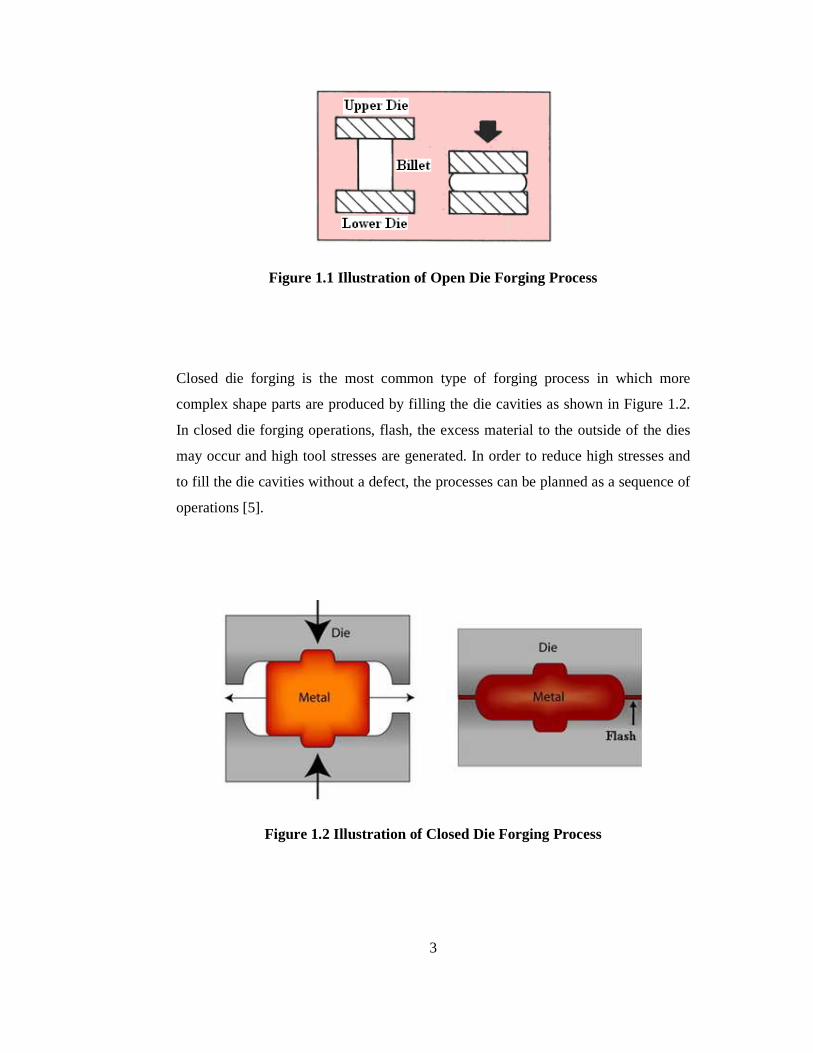
In open die forging, at least one of the workpiece surfaces deforms freely as shown
in Figure 1.1 and as a result of this, open die forging process produces parts of lesser
accuracy and dimensional tolerance than closed die forging process [3]. Open die
forgings can be made with repeated blows in an open die, where the operator controls
the workpiece in the die. During the forming process, as the height of the workpiece
is decreased, cross-section area is increased by the rule of material volume
conservation [4].
3
Figure 1.1 Illustration of Open Die Forging Process
Closed die forging is the most common type of forging process in which more
complex shape parts are produced by filling the die cavities as shown in Figure 1.2.
In closed die forging operations, flash, the excess material to the outside of the dies
may occur and high tool stresses are generated. In order to reduce high stresses and
to fill the die cavities without a defect, the processes can be planned as a sequence of
operations [5].
Figure 1.2 Illustration of Closed Die Forging Process
4
1.1.2 Classification of Forging According to Temperature
Forging operations are classified according to temperature as hot forging, warm
forging and cold forging.
In hot forging process, billet is heated above its recrystallization temperature. Greater
deformation is attained, die wear is reduced and dimensional accuracy is low in hot
forging process. In warm forging process, billet is heated to a temperature which is
between its recrystallization temperature and work hardening temperatures. Warm
forging process provides products with better dimensional tolerances than hot
forging process although forging loads and die wear is greater. On the other hand, in
cold forging process, billet is forged usually at the room temperature. Cold forging
improves mechanical properties and greater dimensional accuracy is achieved.
However, higher force is necessary in cold forging process [6].
1.1.3 Classification of Forging According to Type of Machine
Forging process can be classified in three main groups, which are press, hammer and
roll forging, according to machine type. Several forging parts can be produced by
either hammers or presses, but the processing characteristic of each type of machines
influence the behavior of the metal being forged [7].
Forging press applies a compressing action on the workpiece. Forging presses can be
classified as hydraulic and mechanical according to their actuation. Hydraulic presses
are operated by large pistons and cylinders driven by high pressure hydraulic or
hydro pneumatic systems. They move usually slow speed under pressure after rapid
approach speed. Mechanical presses differ from hydraulic presses in that they force
two working surfaces together by offset cams, cranks and other rigidly connected
mechanical systems. The strokes of mechanical presses are shorter than that of
hammers and hydraulic presses [8].
Forging hammers apply force by the impact of a large ram. The hammer is dropped
from its maximum height, usually raised by steam or air pressure. Metals forged in
hammers are usually display a significant temperature rise during rapid deformation.

5
This is a problem when forging metals like aluminum close to its melting
temperatures. The temperature rise is usually less significant in press forging [8].
1.1.4 Classification of Forging According to the Billet Material
Forging process can be classified in two main groups, which are forging of carbon
and alloy steels and; forging of nonferrous metals such as aluminum alloys,
magnesium alloys and titanium alloys, according to the billet material. Carbon and
alloy steels are the most commonly used forging materials. However, forging of
nonferrous metals have been demanded increasingly and the proper forging design
should be considered according to the specified nonferrous metal. Since, this study is
related to forging of aluminum alloys, the detail of the aluminum forging will be
given in Chapter 2.
1.2 Basic Design Considerations of Forging Process
Forging process has several design parameters that should be considered in forging
process design. The control of the design parameters aids to predict the
characteristics of the final product and as well tooling of the forging process before
the forging operations.
The following design sequence consists of design parameters as can be given in
Figure 1.3 for the forging process and the die design [9].
• Suitable material and its properties should be defined.
• Grain orientation should be controlled by the proper parting line design.
• Flash and machining allowances should be considered.
• Corners, fillets and forging draft should be specified
• Scale allowance should be considered.
• Billet geometry should be defined.

6
• Preform design should be done if necessary.
• Forging loads are predicted.
Figure 1.3 Design Parameters of Forged Part [9]
The various design details, such as the number of preforms, the initial shape of billet
to assure the die filling and flash thickness are often a matter of experience. Each
component is a new design entity and brings its own unique challenges [10].
The details of these parameters for aluminum forging will be mentioned in the
following chapters.
1.3 Computer Aided Design (CAD), Computer Aided Manufacturing (CAM)
Applications and Computer Aided Engineering (CAE) in Forging Process
The main problem for forging process is the high cost and long lead time for the
design and production of tooling. For this purpose, CAD, CAM and CAE techniques
are used to get faster the design and manufacture of tooling by decreasing the trial
and error time to produce successful forgings [11].
7
3-D modeling of forging dies is usually made by the aid of CAD software such as
PRO/ENGINEER, CATIA, etc. Designer of the forging process can easily change
their design parameters in the software if there are any problems in the simulation of
the process by using this type of software.
The usage of process simulation programs is common for research and development
of forging processes. By using this type of programs, forging tool designer could
decrease costs by improving achievable tolerances, increasing tool life, predicting
and preventing flow defects, and predicting part properties. CAD, CAM and CAE
programs develop satisfactory die design for the required process parameters [12];
• To ensure die fill
• To prevent the flow induced defects such as laps and cold shuts.
• To predict processing limits that should not be exceeded so that internal and
surface defects are avoided.
• To predict temperatures so that part properties, friction conditions and die life
can be controlled.
Finite Element Method is a method in which parts are divided into a number of
elements interconnected at a finite number of nodal points. In finite element method,
from the unknown element velocity, equations are formed and stresses and
displacements of the each element are calculated.
Finite Volume Method is a simulation method in which the grid points are fixed in
space and the elements are simply partitions of the space defined by connected grid
points. The finite volume mesh is a fixed frame of reference. The material of a billet
under analysis moves through the finite-volume mesh; the mass, momentum, and
energy of the material are transported from element to element. The finite-volume
solver, therefore, calculates the motion of material through elements of constant
volume, and therefore no remeshing is required. The most common finite volume
software used in forging is MSC SuperForge to predict to forging variables [13].

8
MSC. SuperForge is very supportive in optimizing the forging process and defining
its parameters. Forging process can be simulated, problems related with current
design are observed easily, various dies can be tried and forging process can be
analyzed closely by using SuperForge. After the different simulation processes,
optimum die set for which die cavity is filled completely while maintaining a lower
stress can be selected by using SuperForge [14].
1.4 Previous Studies
Several previous studies have been conducted in METU-BILTIR Research and
Application Center [15-27]. In the study of Alper, he developed a computer program
for axisymmetric press forgings, which designs the forging geometry and the die
cavity for preforms and finishing operation [16]. Elmaskaya studied on upset forging
process and the design limits for tapered preforms had been conducted by using the
finite element method [17]. Kutlu performed the design and analysis of preforms in
hot forging for nonaxisymmetric press forgings [18]. In the study of Đşbir, the finite
element analysis was realized to examine trimming operation on forged parts [19].
Kazancı developed a program for the sequence and die design of solid hot upset
forgings having circular shanks and upset regions with non-circular cross-sections
[20]. Civelekoğlu performed analysis of hot forging for three different alloy steels.
The effects of material selection on the processes were examined [21]. Also, in the
study of Karagözler, the analysis and preform design for long press forgings with
non-planar parting surfaces are realized [22]. Abachi performed the analysis of die
wear. He compared simulation results and experimental results with the measurement
on the worn die [23]. Gülbahar studied on the analysis and design of bent forgings
with planar and non-planar parting surfaces [24]. Furthermore, Aktakka performed
warm forging analysis of a part used in automotive industry [25]. Maşat studied on
precision forging of a spur gear. He proposed a new die design for precision forging
and performed the finite volume analysis and the experiment [26]. Saraç proposed
the forging process sequence design with a preform design in warm forging
temperature range. She performed a finite element analysis to find the die stresses.
She also realized the experimental study [27].

9
Studies in METU-BILTIR Research and Application Center up to now have been
related the forging of steel billets and there is no experience in aluminum forging. On
the other hand, in the literature, there are some studies related to aluminum forging to
be mentioned.
Kim, Ryou, Choi and Hwang analyzed the metal forming processes of aluminum
alloy wheel forging at elevated temperatures by using finite element method. In their
study, they adapted a coupled thermo-mechanical model for the analysis of plastic
deformation and heat transfer in the finite element formulation. They carried out an
experiment for a simplified small-scale model and compared with the simulation in
terms of forging load to verify the validity of the formulation adapted in this study.
Then, they simulated various processes with full-scale model for a 6061 aluminum-
alloy wheel [6].
In the study of Wang, Seo, Cho and Bae, to reduce the press capacity and material
cost in the production of a large aluminum flange, they proposed a forging process
with optimum design parameters. They firstly performed a hot compression test with
cast cylindrical billets in order to determine the optimum forging conditions for the
aluminum flange. In order to find the change in mechanical properties depending on
the effective strain of the cast aluminum billets, they performed a hot upsetting test
with rectangular blocks and then they realized a uniaxial tensile test with specimens
cut from the upset billets. They made finite element analysis to determine the
configurations of the cast preform and die for an aluminum flange. In their study,
they also performed an experiment for an aluminum flange and confirmed that the
optimal configuration of the cast preform predicted by finite element analysis was
very useful [28].
Jensrud and Pedersen investigated cold forging of high strength aluminum alloys and
developed a new thermomechanical processing for the economical forging process
by reducing the preform steps compared with cold forging. Their method is
particularly suitable for parts with narrow geometrical tolerances, good concentricity,
smooth surface finish and for near net shape products [29].

10
Tanner and Robinson studied on the methods to reduce the residual stress in 2014
aluminum alloy forging. Warm water and boiling water was used for quenching of
aluminum alloy and results of these two types of quench method were compared to
obtain which is the best method to reduce the residual stress in aluminum forging. In
their study, closed die forgings manufactured from 2014 aluminum alloys have been
subject to both standard and non-standard heat treatments in order to reduce the as-
quenched residual stress magnitudes. They determined residual stress magnitudes by
the centre hole drilling strain-gauge method and compared the results of two methods
in their study [30].
In the study of Yoshimura and Tanaka, precision forging of aluminum forging and
their parameters were investigated and results were compared with precision forging
of steels. They introduced firstly outline of an enclosed die forging equipment and
then explained some net shape forming examples of steel and aluminum alloys in
detail [31].
Altan, Boulger, Becker, Akgerman and Henning clarified the design parameters of
aluminum forging process in detail [32].
ASM Handbook Committee's Metals Handbook Volume 5 and Volume 14 explain
the aluminum forging process and its properties fully [33-34].
1.5 Scope of the Thesis
Aluminum forging products are extensively used in automotive and aircraft industry
due to their low weight, corrosion resistance behavior and their ability to achieve
high strength and ductility.
In this study, design and analysis of an aluminum forging process will be examined.
This study has been supported by TUBĐTAK, METU-BILTIR Research and
Application Center of Middle East Technical University and AKSAN Steel Forging
Company as a "TUBĐTAK-SANTEZ" project.
In Chapter 2, aluminum alloys, their forgeability, aluminum forging temperatures,
die materials and aluminum forging process will be examined in detail; and in
11
Chapter 3, design parameters of aluminum forging process such as machining
allowances, draft angles, corner and fillet radii, flash geometry and preform design
will be given for the process design. In chapter 4, a particular part and dies will be
designed by using a CAD program according to the aluminum forging design
parameters and the finite volume simulation results such as die force diagrams,
effective stress and temperature distribution figures will be presented by using
commercially available program for the temperature values of 375 oC, 400 oC and
425 oC for 7075-0 type of aluminum alloy. Manufacturing of dies, their dimensions,
assembly of the dies and manufacturing process of the aluminum forging will be
explained in Chapter 5. The experiments will be realized for the 7075-0 type of
aluminum alloy for the forging temperature of 200 oC, 250 oC, 300 oC, 350 oC and
400 oC and their results will be presented also in Chapter 5. In Chapter 6, for a case
study, the finite volume simulations and the experiments will be performed for the
6061-0 type of aluminum alloy for the forging temperatures of 200 oC, 250 oC, 300 oC, 350 oC and 400 oC and their results will be compared with the results obtained in
Chapter 5. Finally, in Chapter 7, conclusions, discussions and suggestions for future
works will be given.

12
CHAPTER 2
ALUMINUM FORGING
2.1 Introduction
Demand for aluminum forging products especially in automotive and aerospace
industry has been increased in recent years due to their lightness, strength and
formability. Aluminum forging products are used in automotive and aerospace
industry for the necessity to make modern vehicles lighter, safer and more
environmental friendly. The automotive industry is one of the major users of
aluminum forged parts since low-fuel-consumption cars have been demanded for the
economy in recent years [35].
The aluminum parts are generally used in the car body, the wheels and the
suspension in modern cars. The suspension components are the most important
aluminum forging parts in modern cars [36]. For example, many of suspension
components need better-quality and reliable properties such as high strength and
toughness. Aluminum forging is a good alternative for such suspension parts with
weight reduction up to 40% [35].
Aluminum forgings provide several advantages over the other types of metals as
follows [37];
• Aluminum alloys are ductile, in high strength with low weight and have a
good corrosion resistance.
13
• In aluminum forging, the grain structure can be arranged to correspond to the
main loading direction leading to high strength and fatigue properties.
• Aluminum forging can be performed in dies heated to essentially the same
temperatures as the workpiece.
• Aluminum alloys do not develop scale during heating.
• Aluminum forging processes require low forging pressure.
Aluminum alloys can be forged into a variety of shapes by open die forging, close
die forging and ring rolling. Aluminum forgings are mostly closed-die forgings.
2.2 Aluminum Alloys
There are wide ranges of aluminum alloys from low-strength aluminum alloys such
as 1100 and 6061 to high strength aluminum alloys such as 7075 in aluminum
forging. Aluminum alloys are most often extruded in the form of aluminum bars
initially, but in some cases, cast billets are also used for production. During the
manufacturing process, a billet is produced which is characterized by a homogeneous
structure completely free of pores and blowholes [36].
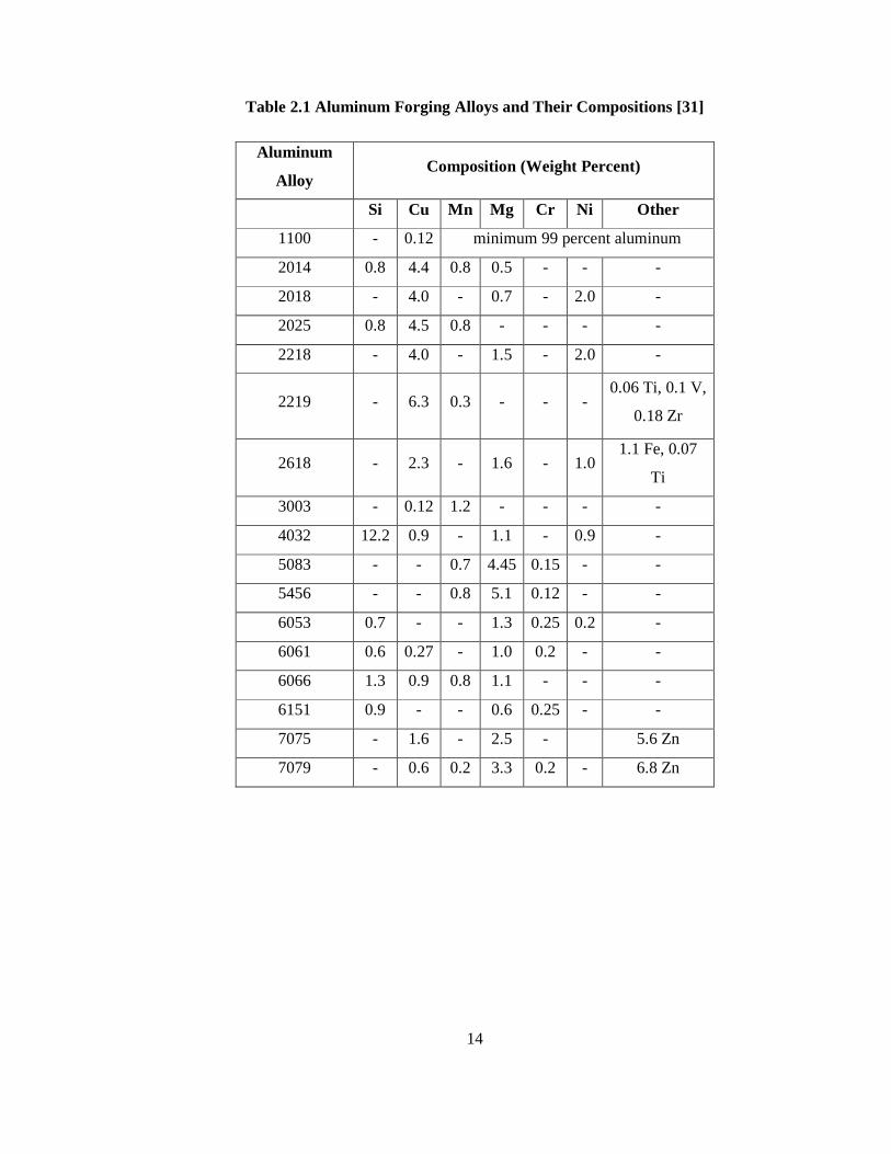
In Table 2.1, most common aluminum forging alloys and their nominal chemical
compositions are given. As can be seen from Table 2.1 as the major alloying
elements change in aluminum alloy, its alloy group also changes.
Aluminum alloys are mostly named and designated with its composition. The first of
the four digits in the designation indicates the alloy group in terms of the major
alloying elements as can be seen in Table 2.2. For example, if the amount of copper
in aluminum alloy composition is high, it is called as 2XXX alloy group although if
the amount of the zinc is high in aluminum alloy composition, alloy group is called
as 7XXX.
14
Table 2.1 Aluminum Forging Alloys and Their Compositions [31]
Aluminum
Alloy Composition (Weight Percent)
Si Cu Mn Mg Cr Ni Other
1100 - 0.12 minimum 99 percent aluminum
2014 0.8 4.4 0.8 0.5 - - -
2018 - 4.0 - 0.7 - 2.0 -
2025 0.8 4.5 0.8 - - - -
2218 - 4.0 - 1.5 - 2.0 -
2219 - 6.3 0.3 - - - 0.06 Ti, 0.1 V,
0.18 Zr
2618 - 2.3 - 1.6 - 1.0 1.1 Fe, 0.07
Ti
3003 - 0.12 1.2 - - - -
4032 12.2 0.9 - 1.1 - 0.9 -
5083 - - 0.7 4.45 0.15 - -
5456 - - 0.8 5.1 0.12 - -
6053 0.7 - - 1.3 0.25 0.2 -
6061 0.6 0.27 - 1.0 0.2 - -
6066 1.3 0.9 0.8 1.1 - - -
6151 0.9 - - 0.6 0.25 - -
7075 - 1.6 - 2.5 - 5.6 Zn
7079 - 0.6 0.2 3.3 0.2 - 6.8 Zn

15
Table 2.2 Aluminum Alloy Groups and Their Major All oying Elements [37]
Alloy
Groups Major Alloying Elements
1XXX
Aluminum with 99.0 % minimum purity and
higher
2XXX Copper
3XXX Manganese
4XXX Silicone
5XXX Magnesium
6XXX Magnesium and Silicon
7XXX Zinc
8XXX Other elements
9XXX Unused series
2.3 Forgeability of Aluminum Alloys
Forgeability is mainly based on the deformation per unit of energy absorbed in the
range of forging temperatures. Also, forgeability can be considered as the difficulty
of achieving specific degrees of severity in deformation. Forgeability is influenced
by primarily the forging process, the forging strain rate, complexity of the shape to
be forged, the lubrication conditions, and the forging and dies temperature [33].
Although aluminum alloys have good forgeability from the standpoint of ductility,
the energy and force requirements change notably with chemical composition of
aluminum alloy and forging temperature. High pressure requirement is the main
reason of less forgeable material usage in forging operation. For example, pure
aluminum, 1100, requires relatively low pressure than alloy 6061 at the same forging
temperatures to produce the same shape [34].
16
Figure 2.1 Flow Stresses of Commonly Forged Aluminum Alloys and of 1025
Steel at Typical Forging Temperatures and Various Levels of Total Strain [33]
Figure 2.1 compares the flow stresses of some commonly forged aluminum alloys at
350 to 370 °C and at a strain rate of 4 to 10 s-1 to 1025 carbon steel forged at an
identical strain rate but at a forging temperature typically employed for this steel. For
some low-to-intermediate strength aluminum alloys, such as 1100 and 6061, flow
stresses are lower than those of carbon steel. For high-strength alloys, particularly
such as 7075 flow stresses, and therefore forging pressures, are considerably higher
than those of carbon steels. That is, high-strength aluminum alloys are less forgeable
at same forging temperatures than low carbon steels as a class of alloys [33].
17
2.4 Forging Temperature for Aluminum
The metal temperature is a critical element in the aluminum forging process and
careful control of temperature during heating is important. Aluminum alloy billets
are heated fairly below their solidus temperature before forging, because the heat
generated during forging deformation causes a temperature rise in the material. If
summation of the initial billet temperature and the temperature rise during forging
exceeds the melting temperature, forging begins to melt, leading to severe cracking
of forging. This effect is mostly significant in high-speed forging, such as on a
mechanical press or forging hammer, because the heat generated has little time to
diffuse into the dies. This reduces the complexity of the shapes that can be produced
on high-speed forging equipment and potentially increases the amount of machining
required [11].
On the other hand, the forgeability of all aluminum alloys improves with increasing
metal temperature, and there is considerable variation in the effect of temperature for
the alloys. In Figure 2.2, forgeability of different aluminum alloys with respect to
temperature changes are given. From the figure, it is easily observed that as the
temperature increases forgeability increases. However, changes in high-strength
alloys such as 7075 are relatively small when compared to the low strength alloys.
In Figure 2.3, effect of temperature on flow stress can be seen. A highly forgeable
aluminum alloy 6061 at a strain rate of 10 s-1 is forged for different temperatures and
dramatic reduction in flow stress is shown in the figure. It is easily seen from the
figure that there is nearly a 50 % increase in flow stress between the highest forging
temperature 480 °C and 370 °C.

18
Figure 2.2 Forgeability and Forging Temperatures of Various Aluminum
Alloys [33]
Figure 2.3 Flow Stress vs. Strain for Alloy 6061 at Three Different Forging
Temperatures [33]
Temperature ranges which have been recommended for forging aluminum alloys are
listed in Table 2.3.
19
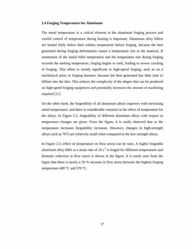
Table 2.3 Recommended Forging Temperature Ranges for Aluminum
Alloys [33]
Forging
Temperature Range Aluminum Alloy
o C
1100 315-405
2014 420-460
2025 420-450
2219 425-470
2618 410-455
3003 315-405
4032 415-460
5083 405-460
6061 430-480
7010 370-440
7039 380-440
7049 360-440
7050 360-440
7075 380-440
In general, most aluminum alloys are forged at about 55 o C below the melting point
temperature, but with dependence on the speed and on the total amount of
deformation. Since the material becomes brittle at the beginning of melting,
appropriate temperature should be chosen for the additional heat is generated during
forging operation may result in melting of aluminum alloy in rapid deformation [38].
20
From Table 2.3, the forging temperature ranges for most alloys are relatively narrow.
Because of this, obtaining and maintaining proper metal temperatures in the forging
of aluminum alloys is critical to the success of the forging process [33].
2.5 Forging Equipment Used for Aluminum Forging
Aluminum alloys can be forged in almost all presses and impact equipment, with a
few exceptions. Aluminum forging should be more carefully performed by hammers
because of aluminum alloy’s lower melting temperatures and a tendency for
temperature increase to occur in the forgings during the usually faster deformation
rates [39].
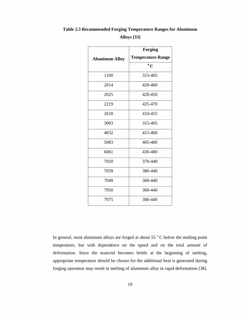
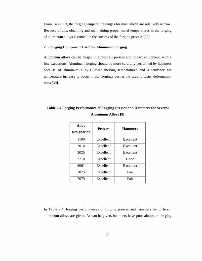
Table 2.4 Forging Performance of Forging Presses and Hammers for Several
Aluminum Alloys [8]
Alloy
Designation Presses Hammers
1100 Excellent Excellent
2014 Excellent Excellent
2025 Excellent Excellent
2218 Excellent Good
6061 Excellent Excellent
7075 Excellent Fair
7079 Excellent Fair
In Table 2.4, forging performances of forging presses and hammers for different
aluminum alloys are given. As can be given, hammers have poor aluminum forging

21
capabilities although presses are suitable most of the aluminum alloys as seen from
the table.
2.6 Die Materials and Die Temperature in Aluminum Forging
The die materials used in the closed-die forging of aluminum alloys are the same as
in steel forging except that, due to the forces applied in aluminum alloy forging and
the complexity of the parts produced; such materials are typically used at lower
hardness levels in order to improve their toughness. H11 (DIN 1.2343), H12
(DIN 1.2606), H13 (DIN 1.2344), or their proprietary variants are usually used at 44
to 50 HRC (i.e. Rockwell Hardness) in aluminum forging [33].
On the other hand, the heating of dies plays very important role in forging operation.
As given in Figure 2.4, forging billets cool very rapidly if dies are not heated due to
conduction between forging billet and the dies from the rule conservation of energy
as shown in following formula;
Q = qcon + qrad+ qconv (2.1)
where; Q = total heat loss
qcon = heat losing by conduction
qrad = heat losing by radiation
qconv = heat losing by convection
These effects can be reduced when dies are heated close to the billet temperatures
where these types of forging operations are called as isothermal forging. Isothermal
forging is feasible with metals like aluminum.
Heating of dies can successfully raise the level of metal plasticity and flow
properties, improve the homogeneity of metal flow, reduce die chilling and decrease
the forging pressure on the material. Therefore, a forging of complicated shape, high

22
dimension of accuracy and a well-distributed internal structure can be produced like
in aluminum forging with the aid of heated dies [41].
Figure 2.4 Cooling of Forging Billet [40]
Table 2.5 Die Temperature Ranges for Different Forging Equipment [33]
Die Temperature
Range Forging Equipment
o C
Mechanical Presses 150-260
Hammers 95-150
Hydraulic Presses 315-430
Roll Forging 95-205
23
In Table 2.5 die temperature ranges for different forging equipment are given. As
seen from the table, the die temperature for the hydraulic presses is higher than the
mechanical presses and hammers. Temperature is kept relatively low in mechanical
presses and hammers because of the temperature raise during rapid deformation.
2.7 Heating Equipment Used for Aluminum Forging
The metal temperature and the die temperature are critical factors in aluminum
forging process. As discussed in Section 2.4, aluminum forging has a very narrow
temperature range and control of the temperature at those ranges is important for the
successful forging operation.
Aluminum alloys billets are heated for forging process with a wide variety of
equipment such as electric furnaces, fully muffled or semi-muffled gas furnaces, oil
furnaces, induction machines. The heating equipment should have pyrometric
controls by which temperature can be maintained within the range +/-5 o C. Most
furnaces should have recording and control devices and are frequently checked for
temperature uniformity [42].
The heating time for aluminum alloys is usually dependent on the section thickness
of the billet and the furnace capabilities. In general, 4 to 8 minutes per 10 mm of
section thickness are enough to ensure that the aluminum alloys have reached the
desired temperature of preheating [36].
The heating of dies is also critical in the aluminum-forging process. Heating
equipments for the dies are mostly gas-fired burners in aluminum forging.
2.8 Lubrication in Aluminum Forging
Lubricants and lubrication of dies are very important in forging operations. There are
several advantages of lubrication in forging operation as followings [8];
• Metal flow can be controlled and improved.
• Lubrication decreases the die friction and helps die filling.
24
• Ease of removal of the forged part from the die can be achieved.
• Lubricants are used to reduce forging loads.
In the selection of lubricants, some important parameters should be considered. For
example, insulating qualities, corrosiveness, permanence and ease of removal are
important characteristics in the selection of lubricant. Water-based fluids, oil-based
fluids and solids are three main lubricant groups in forging operations. The water-
based fluids consist of aqueous solutions, emulsions and dispersions in which they
are mixed with one of the materials such as soaps, fatty oils, fatty acids, mineral oils
and solid fillers. The oil-based fluids range from light mineral oils to heavily
compounded chemically active fluids. They usually contain solid inorganic fillers,
such as mica, graphite and clay. The solid lubricants are either organic or inorganic
solids such as certain plastics and graphite [8].
In aluminum forgings, there are different lubricants existing from kerosene to oil
graphite suspensions. Water-based graphite is most widely used as lubricant in
aluminum forging. Other organic and inorganic compounds are added to colloidal
suspensions in order to achieve the desired results [36]. However, since graphite, has
a black color, is not easily cleaned from the forging, the colorless water-soluble
lubricants have been demanded recently for aluminum forging.
Lubricant application is usually performed by spraying the lubricant onto the dies
while dies are assembled in the press and just before the forging. A pressurized-air or
airless spraying system is usually employed in lubrication of dies [36].
2.9 Trimming in Aluminum Forging
Trimming is the simply flash removal operation after forging is completed. There are
several methods to remove flash from the forging but most common method for
removal of flash is trimming of flash in a trimming press.

25
Small aluminum forgings can be cold trimmed in same way as steel forgings. Larger
forgings can be hot trimmed or band-saw trimmed, depending on size and
configuration [39].
2.10 Heat Treatment of Forged Aluminum Parts
Aluminum forgings are rarely used in the as forged condition. All aluminum alloy
forgings, except from 1xxx, 3xxx and 5xxx series, are heat treated with solution
treatment, quench and artificial aging processes in order to achieve final mechanical
properties. The required mechanical properties are difficult to achieve in aluminum
forging by heat treatment if complex shape and varying cross-sections are forged,
and due to this reason, heat treatment should be performed uniformly and also
carefully [33].
26
CHAPTER 3
DESIGN PARAMETERS OF ALUMINUM FORGING PROCESS
There are several aspects during the design procedure of the forging operations. Part
design and perform design are some of the design steps investigated in this chapter
for aluminum forging.
3.1 Part Design
Parts design mainly includes the standards for machining allowances, parting line
location, draft angles, corner and fillet radii for the aluminum forging.
Machining Allowances
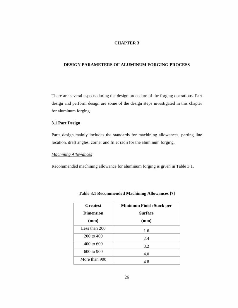
Recommended machining allowance for aluminum forging is given in Table 3.1.
Table 3.1 Recommended Machining Allowances [7]
Greatest
Dimension
(mm)
Minimum Finish Stock per
Surface
(mm)
Less than 200 1.6
200 to 400 2.4
400 to 600 3.2
600 to 900 4.0
More than 900 4.8
27
As shown in Table 3.1, according to FIA (Forging Industry Association), the
allowance is referred to as minimum finish stock per surface and is related to the
largest dimension of forging. Machining allowance may be applied over the entire
forging or to the surfaces to be machined. The finish allowance is applicable to all
metals [7].
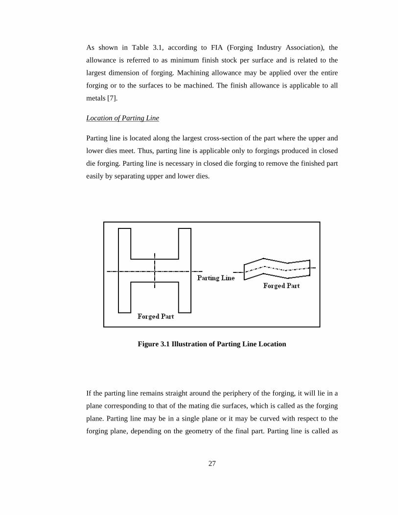
Location of Parting Line
Parting line is located along the largest cross-section of the part where the upper and
lower dies meet. Thus, parting line is applicable only to forgings produced in closed
die forging. Parting line is necessary in closed die forging to remove the finished part
easily by separating upper and lower dies.
Figure 3.1 Illustration of Parting Line Location
If the parting line remains straight around the periphery of the forging, it will lie in a
plane corresponding to that of the mating die surfaces, which is called as the forging
plane. Parting line may be in a single plane or it may be curved with respect to the
forging plane, depending on the geometry of the final part. Parting line is called as

28
straight parting line if it is on the forging plane and parting line is called as broken
parting line if it does not follow the forging plane continuously as shown in
Figure 3.1 [32].
Draft Angle
Draft is the angle or taper on the sides of a forging. Draft is necessary for releasing
the forging from the dies. Draft can be either applied or natural. Natural draft comes
from the part geometry. On the other hand, the applied draft is the taper applied to
the walls of a forging to provide sufficient taper to remove the forging easily. If close
tolerance forging is made, there is zero or one degree draft is specified in the design
of the dies. Thus, strippers or knockout pins are necessary to remove the forging part
from the dies in close tolerance forging. The location of maximum draft on any
vertical surface usually coincides with the parting line [7].
Figure 3.2 Illustration of Draft [37]
There are basically three types of draft as seen in Figure 3.2. External draft is draft
applied to the outer surfaces of perpendicular elements of a forging to the parting
line. Internal draft is applied to the inner surfaces of perpendicular elements of a
forging to the parting line, including the draft in pockets or cavities. Also bottom
draft may exist to provide material flow easily.
29
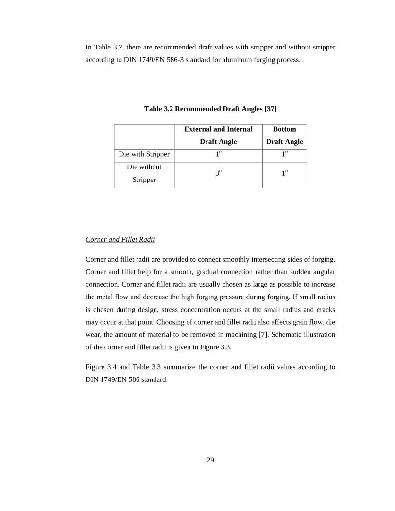
In Table 3.2, there are recommended draft values with stripper and without stripper
according to DIN 1749/EN 586-3 standard for aluminum forging process.
Table 3.2 Recommended Draft Angles [37]
External and Internal
Draft Angle
Bottom
Draft Angle
Die with Stripper 1o 1o
Die without
Stripper 3o 1o
Corner and Fillet Radii
Corner and fillet radii are provided to connect smoothly intersecting sides of forging.
Corner and fillet help for a smooth, gradual connection rather than sudden angular
connection. Corner and fillet radii are usually chosen as large as possible to increase
the metal flow and decrease the high forging pressure during forging. If small radius
is chosen during design, stress concentration occurs at the small radius and cracks
may occur at that point. Choosing of corner and fillet radii also affects grain flow, die
wear, the amount of material to be removed in machining [7]. Schematic illustration
of the corner and fillet radii is given in Figure 3.3.
Figure 3.4 and Table 3.3 summarize the corner and fillet radii values according to
DIN 1749/EN 586 standard.

30
Figure 3.3 Illustrations of Corner and Fillet Radii on Part [43]
Figure 3.4 Determinations of Corner and Fillet Radii [37]
Table 3.3 Recommended Corner and Fillet Radii on Part [37]
Height (h)
mm 0-4 4-10 10-25 25-40 40-63 63-100 100 -
r 1 (Corner) 1.6 1.6 2.5 4 6 10 16
r 2 (Fillet) 2.5 4 6 10 16 20 15

31
Ribs and Webs
A rib is a brace-like projection that is located either at the periphery or on the inside
of a forging. Rib can be forged in either the upper or lower die or both. Ribs are
called as flange when ribs are along the periphery of a forging. The length of ribs is
usually more than three times their width. The design of a rib should reflect the
maximum efficiency in use of materials. Efficiency is related to the load carrying
capacity of a rib. On the other hand, web is the comparatively thin, plate-like element
of the forging. Webs connect ribs and other forged elements. Webs are usually flat
and coincide with the forging plane. Because of their physical connection to other
elements of a forging, the design of webs should be considered with the design of
ribs, the location of parting line, draft and the selection of corner and fillet radii. Due
to the material flow in the vertical sides, webs are very difficult to produce [7].
Figure 3.5 Illustrations of Rib and Web
32
3.2 Shape and Size Factors in Forging
There are limitations to the geometric complexity that can be obtained during forging
process. The force applied to the material by the forging equipment generates
pressure that forces metal to flow into complex cavities of the dies. Spherical and
block like shapes are the easiest to forge in closed dies. Thin and long cavities such
as ribs and webs require high pressure to force the material into them and maximize
the effects of friction and temperature changes. If too much pressure is required, the
total forging load may exceed the capacity of the forging equipment. Also, the
localized stresses in the die due to high pressure in the die cavities may become large
enough to cause overloading failure of the die, fatigue cracking due to repeated
loading and rapid die wear in high metal flow regions. Furthermore, shape
complexity is the possibility of defect formation in the material during forging. As
the material flows around small corner and fillet radii on the dies, laps and cracks
may occur. There is a direct relationship between the surface-volume ratio of a
forging and the difficulty of producing it [11].
3.3. Flash Geometry
Flash is an excess metal around the periphery of the forging in the surrounding area
of the parting line. Flash occurs around the forging part when leaving the closure of
the mating surfaces of the dies. Flash is always related with the parting line and
parting line can divide flash into two pieces [7].
The flash basically serves two main functions. Firstly, flash compensates variation in
billet volume. That is, oversized billets can be used to prevent the billet cutting errors
and metal loses by oxidation during forging. Secondly, flash is useful for controlling
the metal flow. The constriction caused by the flash helps metal to flow and fill the
die cavities [43].
In Figure 3.6, flash and its components are shown. Flash land is the short, flat portion
of flash extending outward from its intersection with the forging as seen from the
figure. Flash gutter is a space after the flash land where excess material is

33
accumulated. The gutter is designed to be slightly oversize to accommodate all the
excess metal [7].
Figure 3.6 Flash Designs [43]
There are significant differences in the design of flash for aluminum from steel
forging. Flash and flash land thicknesses are usually much thinner in aluminum
forging. However, relatively small changes in the flash thicknesses can result in great
changes in the forging pressure requirements. Thus, the flash design should be made
carefully to avoid overloading during forging operation. In Table 3.4, minimum
recommended die closure or flash thickness according to FIA (Forging Industry
Association) are given for the several types of materials. Flash thickness tolerances
are related to type of metal and on the plan area of the forging at the parting line as
can be seen form the table. Although as the plan area increases, flash thickness
differences increases between aluminum and steel forging. Since the forging loads
are lower in aluminum forging, flash thicknesses are relatively thinner as given in the
table.
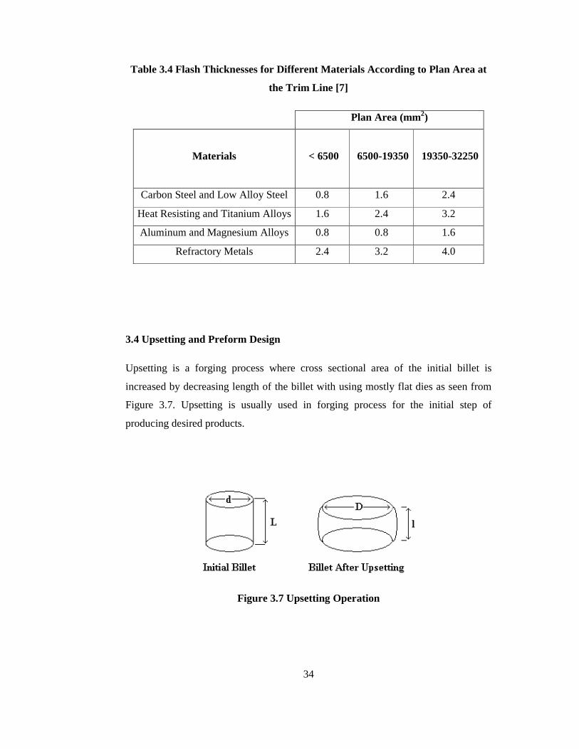
34
Table 3.4 Flash Thicknesses for Different Materials According to Plan Area at
the Trim Line [7]
Plan Area (mm2)
Materials < 6500 6500-19350 19350-32250
Carbon Steel and Low Alloy Steel 0.8 1.6 2.4
Heat Resisting and Titanium Alloys 1.6 2.4 3.2
Aluminum and Magnesium Alloys 0.8 0.8 1.6
Refractory Metals 2.4 3.2 4.0
3.4 Upsetting and Preform Design
Upsetting is a forging process where cross sectional area of the initial billet is
increased by decreasing length of the billet with using mostly flat dies as seen from
Figure 3.7. Upsetting is usually used in forging process for the initial step of
producing desired products.
Figure 3.7 Upsetting Operation

35
Figure 3.8 Planes and Directions of Metal Flow during Forging [32]
On the other hand, design of the preform in closed die forging is one of the most
important aspects. Defect free metal flow, complete die fill and minimum metal
losses into flash can be achieved in the final forging operation with proper forging
process design. However, determination of the preform geometry is a particularly
difficult design step. Metal flow in the preform die should be clearly understood to
make the proper preform design. In the study of metal flow for designing the
preform, it is very useful to consider various cross sections of a forging where the
flow is almost in one plane as given in Figure 3.8. It is common practice in designing
a preform to consider planes of metal flow, that is, selected cross sections of the
forging, and to design the preform configuration for each cross section based on

36
metal flow. The basic design parameters of the preform design can be given as
follows [32];
• The area of each cross section along the length of the preform should be
equal or less than the finished cross sections.
• All corner and fillet radii should be larger than the radii of finished part in
preform.
• The dimension of the preform should be larger than those of the finished part
in the forging direction so that metal flow is mostly of the upsetting type
rather than of the extrusion type (Figure 3.9).
Figure 3.9 Examples of Preform Cross Section Design [33]
In Table 3.5, the recommended preform dimensions for aluminum forging according
to the finish forging dimensions are given. In table, first subscript F and P in the

37
dimension refer to finish and preform respectively. In addition, as seen from the table
the draft angles in preform are nearly same as finish forging and other dimensions
are larger in preform.
Table 3.5 Dimensions in Preform for Aluminum Forging [32]
Dimensions in Finish Forging Dimensions in Preform
Fillet Radii, RFF RPF = (1.2 to 2) RFF
Corner Radii, RFC RPC = (1.2 to 2) RFC
Draft Angle, αF αP ≈ αF

38
CHAPTER 4
DESIGN OF ALUMINUM FORGING AND FINITE VOLUME ANALYS IS OF ALUMINUM FORGING PROCESS
4.1 Case Study for Aluminum Forging Process
In this study, a part which was previously forged in three stages from a cylindrical
steel billet with a diameter of 30 mm and a height of 30 mm at AKSAN Steel
Forging Company as given in Figure 4.1 will be considered. A study was previously
completed in METU-BILTIR Center for warm forging of the part with the steel
material [27]. In this thesis, aluminum forging will be analyzed to produce the
similar geometry from aluminum billet.
Figure 4.1 Steel Forged Part

39
Based on the part geometry given in Figure 4.1, 3-D modeling of the part and dies
has been realized by using PRO/ENGINEER Wildfire 3.0 [44]. In the simulation
process, aluminum forging in different temperatures for the modeled part has been
investigated and proper forging stages have been defined to fill the forging dies
without any defects by using Finite Volume Method (FVM) with sfForming 8.0
module of Simufact 3.0 [45]. Results for the finite volume simulation of the process
will be provided in this chapter for the aluminum alloy 7075-0. In the following
section, 3-D modeling of the part will be explained in detail.
4.2 3-D Modeling of Forging Part
3-D model of the forging is given in Figure 4.2 and its technical drawing is given in
Appendix A.
Figure 4.2 3-D Modeling of Forging
There are some important parameters such as draft angles, parting line location and
flash thickness in modeling of the part for the design of the forging.
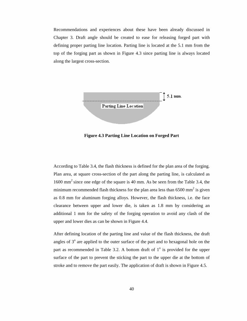
40
Recommendations and experiences about these have been already discussed in
Chapter 3. Draft angle should be created to ease for releasing forged part with
defining proper parting line location. Parting line is located at the 5.1 mm from the
top of the forging part as shown in Figure 4.3 since parting line is always located
along the largest cross-section.
Figure 4.3 Parting Line Location on Forged Part
According to Table 3.4, the flash thickness is defined for the plan area of the forging.
Plan area, at square cross-section of the part along the parting line, is calculated as
1600 mm2 since one edge of the square is 40 mm. As be seen from the Table 3.4, the
minimum recommended flash thickness for the plan area less than 6500 mm2 is given
as 0.8 mm for aluminum forging alloys. However, the flash thickness, i.e. the face
clearance between upper and lower die, is taken as 1.8 mm by considering an
additional 1 mm for the safety of the forging operation to avoid any clash of the
upper and lower dies as can be shown in Figure 4.4.
After defining location of the parting line and value of the flash thickness, the draft
angles of 3o are applied to the outer surface of the part and to hexagonal hole on the
part as recommended in Table 3.2. A bottom draft of 1o is provided for the upper
surface of the part to prevent the sticking the part to the upper die at the bottom of
stroke and to remove the part easily. The application of draft is shown in Figure 4.5.

41
Figure 4.4 Illustration of Flash Thickness on Part
Figure 4.5 Draft Angles on Part
The corner and fillet radii are considered as described in the technical drawing of the
particular forging in Appendix A.
4.3 Aluminum Forging Die Design
In aluminum forging die design, different type of die configuration should be
considered according to forging process stages such as upsetting, preform and finish
stages.
Before the design of the dies, it should be cleared that what type of forging machine
is going to be used and design should be made according to that forging machine. In

42
the experiments, the 10 MN SMERAL mechanical press available in METU-BILTIR
Center Forging Research and Application Laboratory is going to be used. The
technical information about the 10 MN SMERAL mechanical press is given in
Appendix B. In this machine, a die holder is used to mount die blocks. There are
three housings on the die holder to fasten three die blocks as seen in Figure 4.6.
Figure 4.6 View of the Lower Die Holder on Press
In Figure 4.7 and Figure 4.8, top and front views of the die housings of die holder are
given. According to forging stages, three different types of forging die can be used in
this mechanical press. However, as seen from the Figure 4.7, the middle housing has
the largest diameter and it is usually used for the finish forging stage. On the other
hand, height of the die set is restricted to 200 mm as seen Figure 4.8 when dies are at
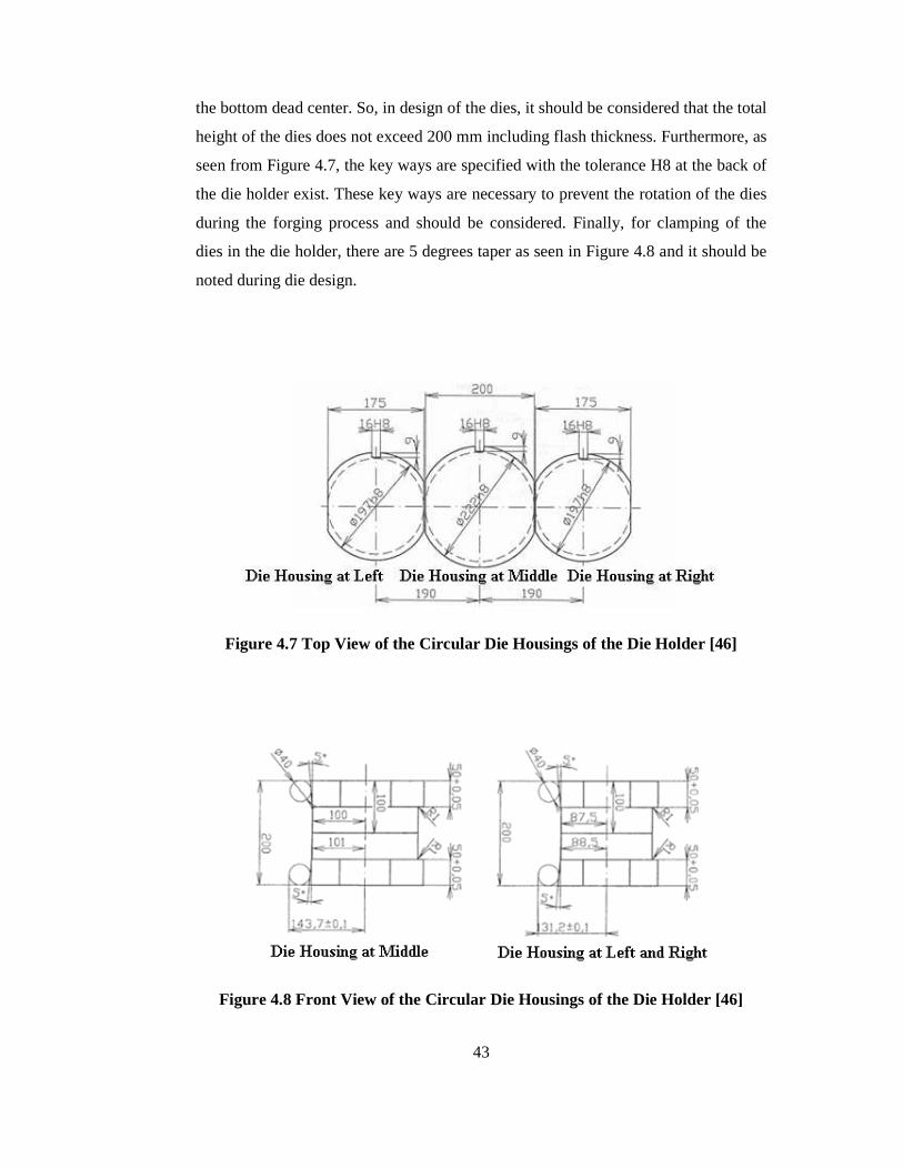
43
the bottom dead center. So, in design of the dies, it should be considered that the total
height of the dies does not exceed 200 mm including flash thickness. Furthermore, as
seen from Figure 4.7, the key ways are specified with the tolerance H8 at the back of
the die holder exist. These key ways are necessary to prevent the rotation of the dies
during the forging process and should be considered. Finally, for clamping of the
dies in the die holder, there are 5 degrees taper as seen in Figure 4.8 and it should be
noted during die design.
Figure 4.7 Top View of the Circular Die Housings of the Die Holder [46]
Figure 4.8 Front View of the Circular Die Housings of the Die Holder [46]

44
According to the constraints of the die holder, the upper and the lower dies in the
finish stage are designed based on the designed part geometry. In design of the upper
and lower dies, a shrinkage allowance of 1.5 % is taken since some shrinkage occurs
after the forged part cools. Total height of the upper and lower die is 200 mm by
considering the flash thickness when the press is at the bottom dead center. Hence,
the dies are designed by considering 99.1 mm in height and by adding flash
thicknesses of 1.8 mm, the total height of the dies becomes 200 mm. As seen in
Figure 4.9, the flash land is provided at the circumference of the die cavity. Since the
die housing at the middle is going to be used for the finish stage, the upper and lower
finish dies will have an external diameter of 222 mm and outer geometry of the dies
are modeled according to the dimensions given in Figures 4.7-4.8. The key ways are
also modeled with 16 mm in width and 9 mm in depth to prevent the rotational
motion of the dies relative to the die holder. The gutter is not designed since it is not
used in the finish die. The detailed technical drawings of the finish dies are given in
Appendix C.
Figure 4.9 3-D Model of Lower and Upper Finish Dies

45
Furthermore, front view of the die assembly is shown in Figure 4.10. As seen in the
figure, there is a step like structure in the dies. These types of step are required for
the positioning and alignment of the upper and lower dies with respect to each other.
Also, as seen in the figure, edges at the both side of the dies are cut according to die
holder geometry, since generally more than one die is considered to be used for the
forging operation during analysis and experiments.
Figure 4.10 Front View of Finish Die Assembly
4.4 Simulation Process Parameters for Finite Volume Method
The finite volume method has been used for many years in analyzing the flow of
materials in a liquid state. However, in recent years, some other computer simulation
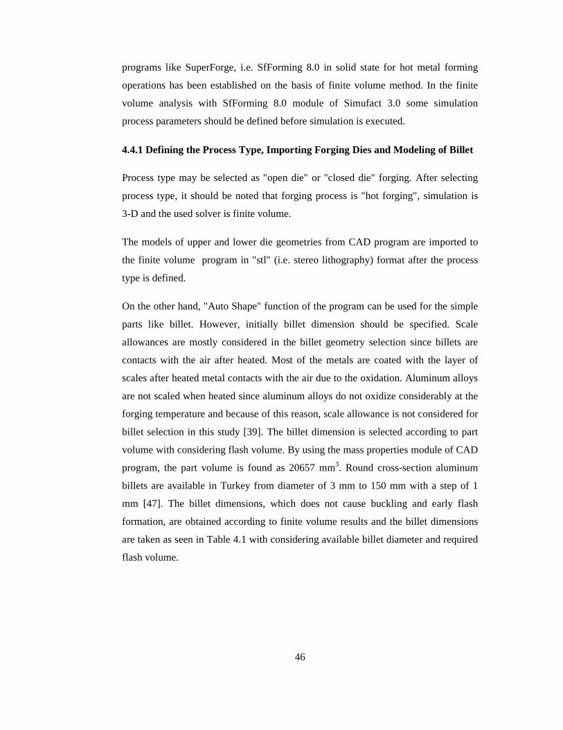
46
programs like SuperForge, i.e. SfForming 8.0 in solid state for hot metal forming
operations has been established on the basis of finite volume method. In the finite
volume analysis with SfForming 8.0 module of Simufact 3.0 some simulation
process parameters should be defined before simulation is executed.
4.4.1 Defining the Process Type, Importing Forging Dies and Modeling of Billet
Process type may be selected as "open die" or "closed die" forging. After selecting
process type, it should be noted that forging process is "hot forging", simulation is
3-D and the used solver is finite volume.
The models of upper and lower die geometries from CAD program are imported to
the finite volume program in "stl" (i.e. stereo lithography) format after the process
type is defined.
On the other hand, "Auto Shape" function of the program can be used for the simple
parts like billet. However, initially billet dimension should be specified. Scale
allowances are mostly considered in the billet geometry selection since billets are
contacts with the air after heated. Most of the metals are coated with the layer of
scales after heated metal contacts with the air due to the oxidation. Aluminum alloys
are not scaled when heated since aluminum alloys do not oxidize considerably at the
forging temperature and because of this reason, scale allowance is not considered for
billet selection in this study [39]. The billet dimension is selected according to part
volume with considering flash volume. By using the mass properties module of CAD
program, the part volume is found as 20657 mm3. Round cross-section aluminum
billets are available in Turkey from diameter of 3 mm to 150 mm with a step of 1
mm [47]. The billet dimensions, which does not cause buckling and early flash
formation, are obtained according to finite volume results and the billet dimensions
are taken as seen in Table 4.1 with considering available billet diameter and required
flash volume.
47
Table 4.1 Billet Geometry and Billet Dimension
Billet Geometry Billet Dimension
(mm)
Cylindrical Shape 30 mm in diameter
32 mm in height
4.4.2 Assigning the Material Properties of Dies and Billet
In this analysis, the dies are considered as rigid die with heat conduction. Because of
this reason, the die material is not defined although different types of die material
data exist in the material library of SfForming 8.0 [45].
The billet material is chosen according to recommendation of FNSS which is one of
the most important defense company in Turkey and which uses the aluminum
forgings in their products [48]. 7075-0 type of aluminum alloy is chosen since that
type of aluminum alloys are extensively used in aerospace, automotive and defense
industry with its high strength, low density, and low cost. 7075-0 type of aluminum
alloy is available in material database of SfForming 8.0 [45] for the hot forging
temperature range of 400-550 oC.
The flow stress-strain rate relation for the different type of hot forging temperatures
is as follows [32] :
mC )(εσ &= (4.1)
where; σ : flow stress
C: yield constant
ε& : strain rate

48
m: strain rate hardening exponent
In Table 4.2, some parameters related with the Equation 4.1 are given to define flow
stress for strain value of 0.115 in different forging temperatures.
According to Equation 4.1 and Table 4.2, flow stress-strain rate curves of 7075-0 for
the strain of 0.115 in different temperatures are obtained as shown in Figure 4.11.
Table 4.2 Flow Stress Parameters for 7075-0 [45]
Yield Stress according to Temperature Strain Rate (1/s)
400 oC 450 oC 500 oC 550 oC
0.01 45.55 22.22 13.48 9.14
0.34 62.57 35.76 22.87 16.65
0.67 66.51 39.19 25.32 18.68
1.00 68.95 41.37 26.89 20.00
Tensile yield strength and ultimate tensile strength of the aluminum alloy 7075-0 are
given in Equations 4.2 and 4.3 according to the simple tension test at the room
temperature [49].
=Yσ 103 MPa (4.2)
=UTSσ 228 MPa (4.3)
Also, some basic material constant and heat material constant are specified as shown
in Table 4.3 [45].

49
Figure 4.11 Stress-Strain Rate Curves of 7075-0 for Different Temperatures [45]
Table 4.3 Material Properties of 7075-0 [45]
Material Property Value
Young's Modulus (GPa) 72
Poisson's Ratio 0.33
Density (kg/m3) 2810
Thermal Conductivity (Watt/(m*K)) 173
Specific Heat Constant (Joule/(kg*K)) 960
Coefficient of Thermal Expansion (1/K) 2.52e-5
Solidus Point (oC) 477
Melting Point (oC) 635

50
4.4.3 Initial Temperature of Billet and Dies
Initial temperatures of the billet are taken as 375 oC, 400 oC, 425 oC and simulation is
made for these temperature values. On the other hand, temperature of the dies during
the aluminum forging process is recommended as 150 °C to 260 °C for the closed die
forging [36]. So, initial temperature of the dies is assumed as 200 °C during the
analysis. Parameters directly used in analysis are given as follows according to
SfForming 8.0 [45];
Ambient temperature: 25°C
Emissivity for heat radiation to ambient: 0.25
Heat transfer coefficient to ambient: 50 W/m2.K
Heat transfer coefficient to workpiece: 6000 W/m2.K
4.4.4 Defining the Coefficient of Friction
Friction between die and billet is an important consideration in a metal forming
process. Such friction produces a tangential (shear) force at the interface between die
and billet which restricts movement of the material and results in increased energy
and press forces. The magnitude of the shear friction stress influences the
deformation pattern, temperature rise, the tool deflection and total force in metal
forming [50].
The friction coefficient is ranged from 0.06 to 0.24 in aluminum forging with the test
previously done [32]. In this study, plastic shear friction is used with a coefficient of
0.2 since high loads are applied in forging operations.
4.4.5 Defining the Press in Finite Volume Program
Schematic illustration of the crank press is shown in Figure 4.12 and properties of it
related with the available press in METU-BILTIR Center Forging Research and
Application Laboratory are given in Table 4.4.

51
Figure 4.12 Schematic Illustration of Crank Press [45]
Table 4.4 Properties of Crank Press available in METU-BILTIR Center
Crank Radius
(mm)
Rod Length
(mm)
Revolution Speed
(rpm)
110 750 100
4.4.6 Defining Forming Properties
Forming parameters are defined to initiate the simulation program as given in
Table 4.5. Element sizes in finite volume program should be assigned for the billet.
The stroke length depends on billet dimension and not shown in the table.
Table 4.5 Forming Properties in Finite Volume Analysis
Workpiece Element Size (mm) 1
Output Divisions 21
Finite Volume Ratio 0.2
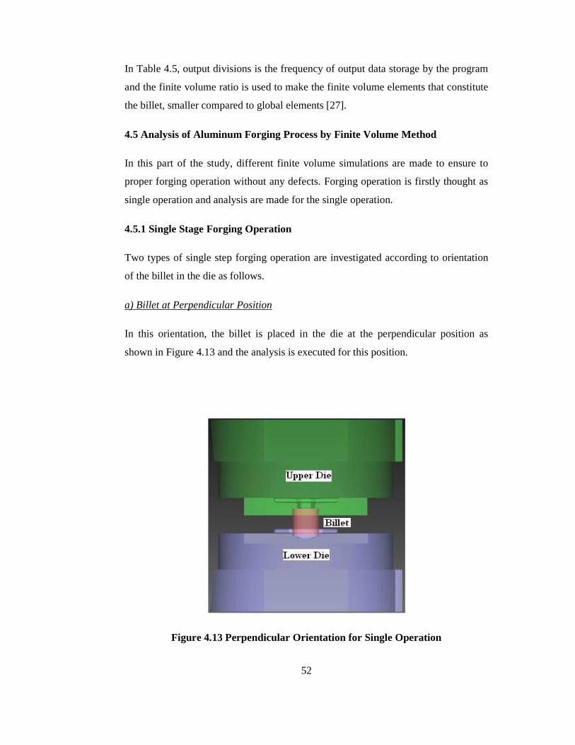
52
In Table 4.5, output divisions is the frequency of output data storage by the program
and the finite volume ratio is used to make the finite volume elements that constitute
the billet, smaller compared to global elements [27].
4.5 Analysis of Aluminum Forging Process by Finite Volume Method
In this part of the study, different finite volume simulations are made to ensure to
proper forging operation without any defects. Forging operation is firstly thought as
single operation and analysis are made for the single operation.
4.5.1 Single Stage Forging Operation
Two types of single step forging operation are investigated according to orientation
of the billet in the die as follows.
a) Billet at Perpendicular Position
In this orientation, the billet is placed in the die at the perpendicular position as
shown in Figure 4.13 and the analysis is executed for this position.
Figure 4.13 Perpendicular Orientation for Single Operation

53
The die and forging part contact is the important feature for the analysis since die
filling is important during forging operation. In Figure 4.14, die filling of this type of
orientation is given. In the Figure 4.14, blue color shows that billet does not contact
with forging dies and red color shows that billet contacts with the dies. The die is
completely filled as seen in Figure 4.14.
Figure 4.14 Die Filling for Perpendicular Orientation at 400 oC
Figure 4.15 Folds in Perpendicular Orientation at 400 oC
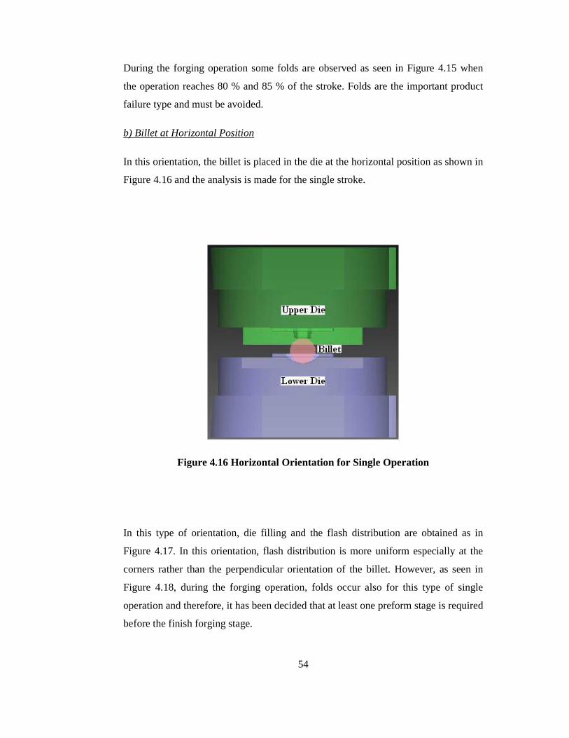
54
During the forging operation some folds are observed as seen in Figure 4.15 when
the operation reaches 80 % and 85 % of the stroke. Folds are the important product
failure type and must be avoided.
b) Billet at Horizontal Position
In this orientation, the billet is placed in the die at the horizontal position as shown in
Figure 4.16 and the analysis is made for the single stroke.
Figure 4.16 Horizontal Orientation for Single Operation
In this type of orientation, die filling and the flash distribution are obtained as in
Figure 4.17. In this orientation, flash distribution is more uniform especially at the
corners rather than the perpendicular orientation of the billet. However, as seen in
Figure 4.18, during the forging operation, folds occur also for this type of single
operation and therefore, it has been decided that at least one preform stage is required
before the finish forging stage.

55
Figure 4.17 Die Filling for Horizontal Orientation at 400 oC
Figure 4.18 Folds in Horizontal Orientation at 400 oC
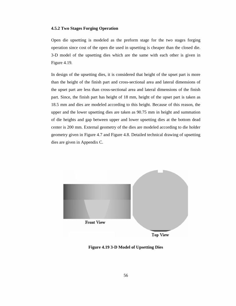
56
4.5.2 Two Stages Forging Operation
Open die upsetting is modeled as the preform stage for the two stages forging
operation since cost of the open die used in upsetting is cheaper than the closed die.
3-D model of the upsetting dies which are the same with each other is given in
Figure 4.19.
In design of the upsetting dies, it is considered that height of the upset part is more
than the height of the finish part and cross-sectional area and lateral dimensions of
the upset part are less than cross-sectional area and lateral dimensions of the finish
part. Since, the finish part has height of 18 mm, height of the upset part is taken as
18.5 mm and dies are modeled according to this height. Because of this reason, the
upper and the lower upsetting dies are taken as 90.75 mm in height and summation
of die heights and gap between upper and lower upsetting dies at the bottom dead
center is 200 mm. External geometry of the dies are modeled according to die holder
geometry given in Figure 4.7 and Figure 4.8. Detailed technical drawing of upsetting
dies are given in Appendix C.
Figure 4.19 3-D Model of Upsetting Dies
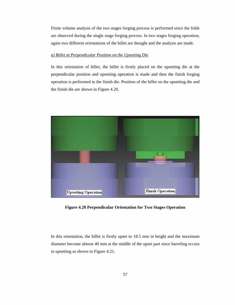
57
Finite volume analysis of the two stages forging process is performed since the folds
are observed during the single stage forging process. In two stages forging operation,
again two different orientations of the billet are thought and the analysis are made.
a) Billet at Perpendicular Position on the Upsetting Die
In this orientation of billet, the billet is firstly placed on the upsetting die at the
perpendicular position and upsetting operation is made and then the finish forging
operation is performed in the finish die. Position of the billet on the upsetting die and
the finish die are shown in Figure 4.20.
Figure 4.20 Perpendicular Orientation for Two Stages Operation
In this orientation, the billet is firstly upset to 18.5 mm in height and the maximum
diameter become almost 40 mm at the middle of the upset part since barreling occurs
in upsetting as shown in Figure 4.21.
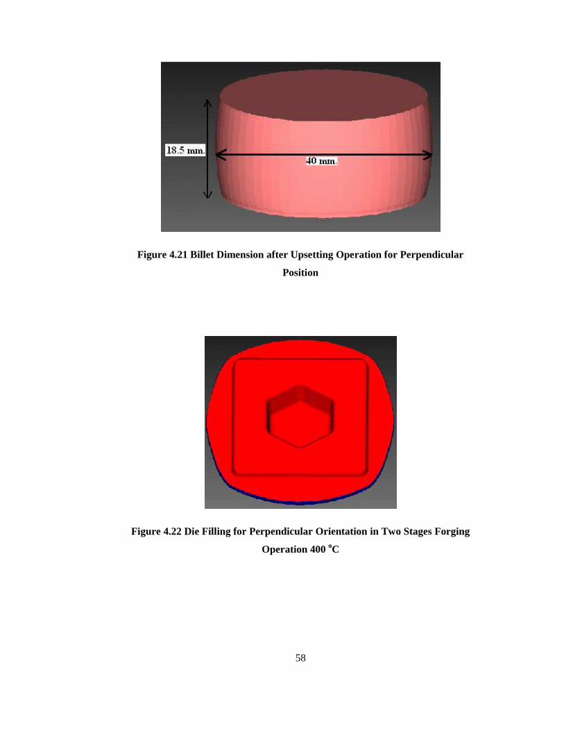
58
Figure 4.21 Billet Dimension after Upsetting Operation for Perpendicular
Position
Figure 4.22 Die Filling for Perpendicular Orientation in Two Stages Forging
Operation 400 oC

59
Figure 4.23 Observation of No Folds in Perpendicular Orientation in Two
Stages Forging Operation at 400 oC
After the upsetting operation is completed, the preform is forged in the finish dies.
The finish die is completely filled as seen in Figure 4.22 and there is not any folds in
this two stages operation as shown in Figure 4.23. However, as mentioned
previously, in this type of orientation, the flash formation at the corners are not
uniform. Also, the maximum diameter of upset part after upsetting operation is
nearly same as the width of the finish part and this violates the rule of preform
design. For these reasons, the horizontal orientation in two stages forging operation
is also performed.
b) Billet at Horizontal Position on the Upsetting Die
In this orientation, the billet is firstly placed on the upsetting die at the horizontal
position and the upsetting operation is applied and then the finish forging operation is
performed in the finish die. Position of the billet on the upsetting die and the finish
die are shown in Figure 4.24. In this orientation, the billet is firstly upset to 18.5 mm
in height and width of the part in x-direction becomes 37.4 mm and width of the part
in y-direction becomes 38.5 mm as shown in Figure 4.25.
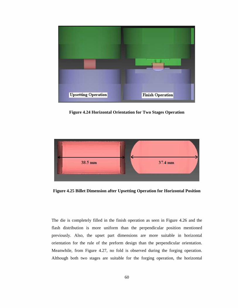
60
Figure 4.24 Horizontal Orientation for Two Stages Operation
Figure 4.25 Billet Dimension after Upsetting Operation for Horizontal Position
The die is completely filled in the finish operation as seen in Figure 4.26 and the
flash distribution is more uniform than the perpendicular position mentioned
previously. Also, the upset part dimensions are more suitable in horizontal
orientation for the rule of the preform design than the perpendicular orientation.
Meanwhile, from Figure 4.27, no fold is observed during the forging operation.
Although both two stages are suitable for the forging operation, the horizontal
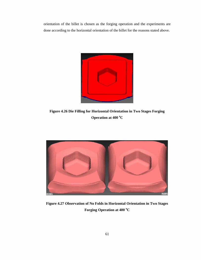
61
orientation of the billet is chosen as the forging operation and the experiments are
done according to the horizontal orientation of the billet for the reasons stated above.
Figure 4.26 Die Filling for Horizontal Orientation in Two Stages Forging
Operation at 400 oC
Figure 4.27 Observation of No Folds in Horizontal Orientation in Two Stages
Forging Operation at 400 oC
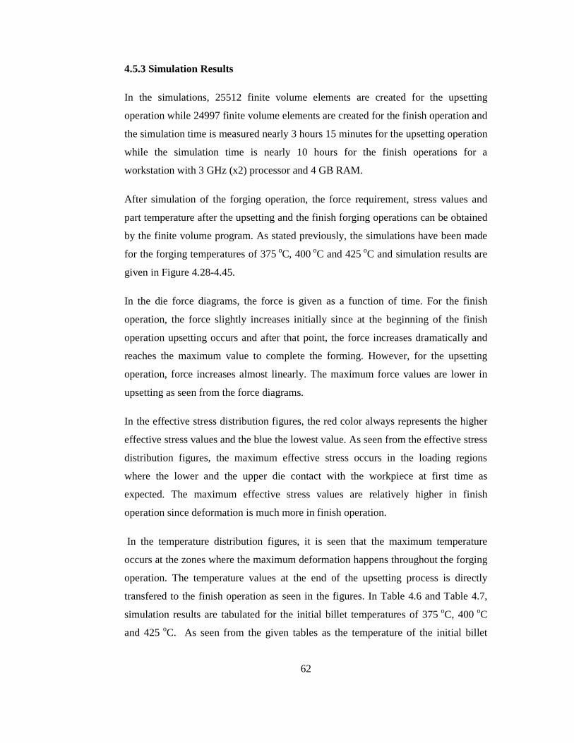
62
4.5.3 Simulation Results
In the simulations, 25512 finite volume elements are created for the upsetting
operation while 24997 finite volume elements are created for the finish operation and
the simulation time is measured nearly 3 hours 15 minutes for the upsetting operation
while the simulation time is nearly 10 hours for the finish operations for a
workstation with 3 GHz (x2) processor and 4 GB RAM.
After simulation of the forging operation, the force requirement, stress values and
part temperature after the upsetting and the finish forging operations can be obtained
by the finite volume program. As stated previously, the simulations have been made
for the forging temperatures of 375 oC, 400 oC and 425 oC and simulation results are
given in Figure 4.28-4.45.
In the die force diagrams, the force is given as a function of time. For the finish
operation, the force slightly increases initially since at the beginning of the finish
operation upsetting occurs and after that point, the force increases dramatically and
reaches the maximum value to complete the forming. However, for the upsetting
operation, force increases almost linearly. The maximum force values are lower in
upsetting as seen from the force diagrams.
In the effective stress distribution figures, the red color always represents the higher
effective stress values and the blue the lowest value. As seen from the effective stress
distribution figures, the maximum effective stress occurs in the loading regions
where the lower and the upper die contact with the workpiece at first time as
expected. The maximum effective stress values are relatively higher in finish
operation since deformation is much more in finish operation.
In the temperature distribution figures, it is seen that the maximum temperature
occurs at the zones where the maximum deformation happens throughout the forging
operation. The temperature values at the end of the upsetting process is directly
transfered to the finish operation as seen in the figures. In Table 4.6 and Table 4.7,
simulation results are tabulated for the initial billet temperatures of 375 oC, 400 oC
and 425 oC. As seen from the given tables as the temperature of the initial billet
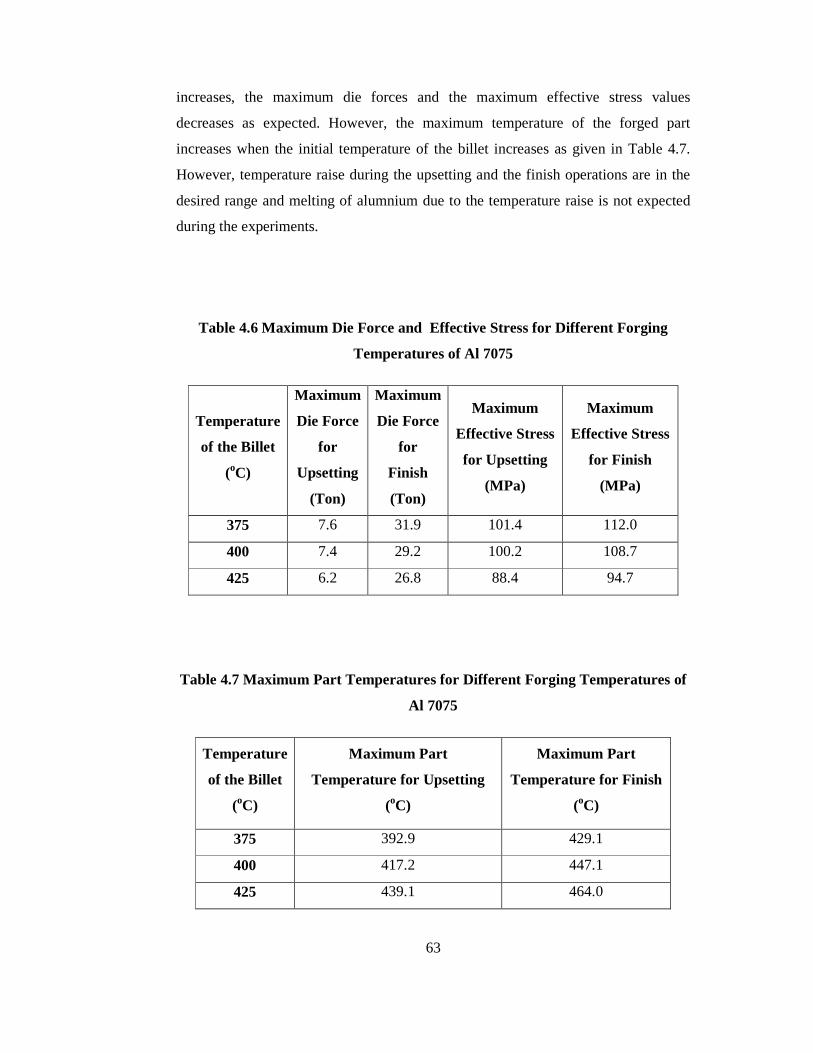
63
increases, the maximum die forces and the maximum effective stress values
decreases as expected. However, the maximum temperature of the forged part
increases when the initial temperature of the billet increases as given in Table 4.7.
However, temperature raise during the upsetting and the finish operations are in the
desired range and melting of alumnium due to the temperature raise is not expected
during the experiments.
Table 4.6 Maximum Die Force and Effective Stress for Different Forging
Temperatures of Al 7075
Temperature
of the Billet
(oC)
Maximum
Die Force
for
Upsetting
(Ton)
Maximum
Die Force
for
Finish
(Ton)
Maximum
Effective Stress
for Upsetting
(MPa)
Maximum
Effective Stress
for Finish
(MPa)
375 7.6 31.9 101.4 112.0
400 7.4 29.2 100.2 108.7
425 6.2 26.8 88.4 94.7
Table 4.7 Maximum Part Temperatures for Different Forging Temperatures of
Al 7075
Temperature
of the Billet
(oC)
Maximum Part
Temperature for Upsetting
(oC)
Maximum Part
Temperature for Finish
(oC)
375 392.9 429.1
400 417.2 447.1
425 439.1 464.0
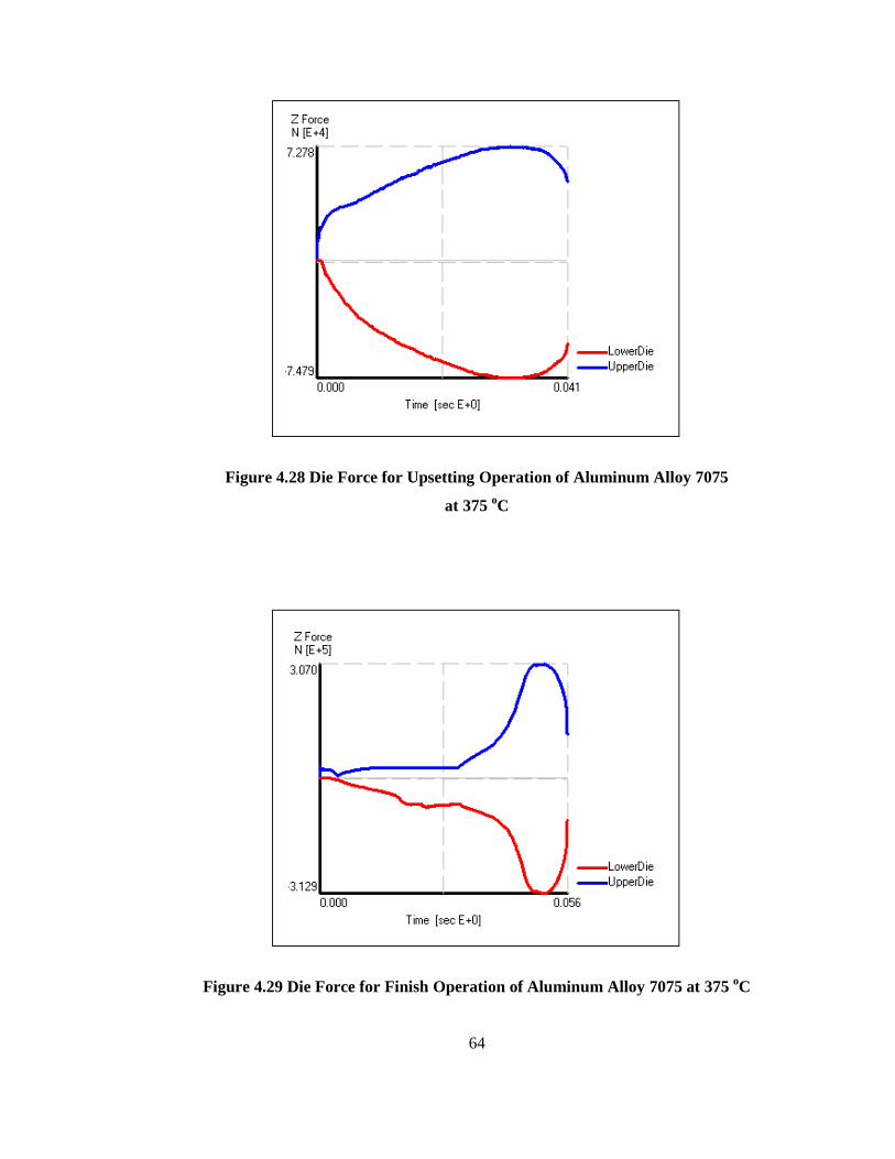
64
Figure 4.28 Die Force for Upsetting Operation of Aluminum Alloy 7075
at 375 oC
Figure 4.29 Die Force for Finish Operation of Aluminum Alloy 7075 at 375 oC
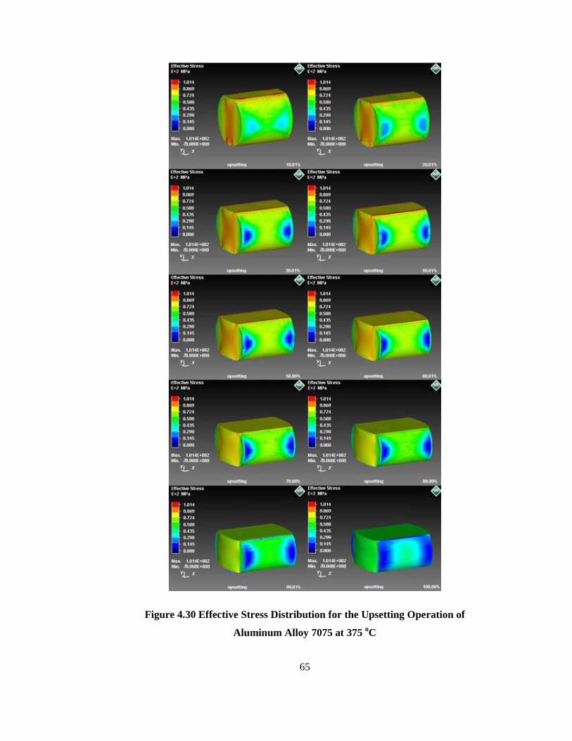
65
Figure 4.30 Effective Stress Distribution for the Upsetting Operation of
Aluminum Alloy 7075 at 375 oC

66
Figure 4.31 Effective Stress Distribution for the Finish Operation of
Aluminum Alloy 7075 at 375 oC

67
Figure 4.32 Temperature Distribution for Upsetting Operation of Aluminum
Alloy 7075 at 375 oC
Figure 4.33 Temperature Distribution for Finish Operation of Aluminum
Alloy 7075 at 375 oC

68
Figure 4.34 Die Force for Upsetting Operation of Aluminum Alloy 7075
at 400 oC
Figure 4.35 Die Force for Finish Operation of Aluminum Alloy 7075 at 400 oC
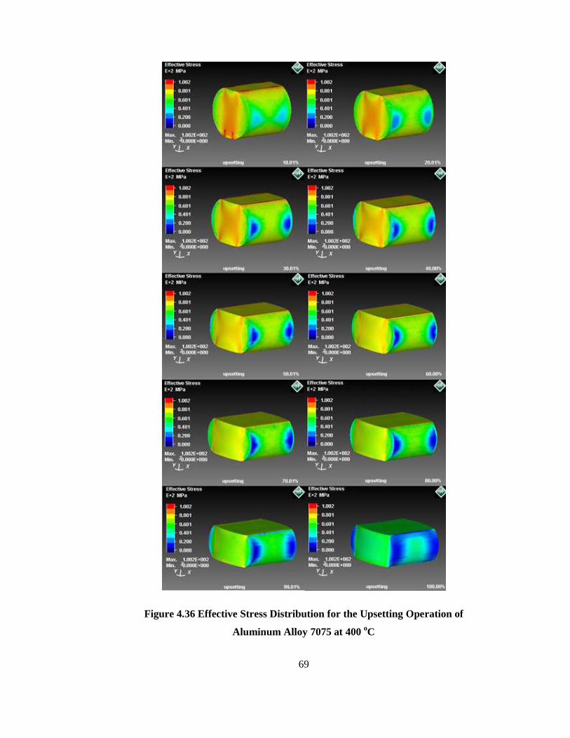
69
Figure 4.36 Effective Stress Distribution for the Upsetting Operation of
Aluminum Alloy 7075 at 400 oC

70
Figure 4.37 Effective Stress Distribution for the Finish Operation of
Aluminum Alloy 7075 at 400 oC
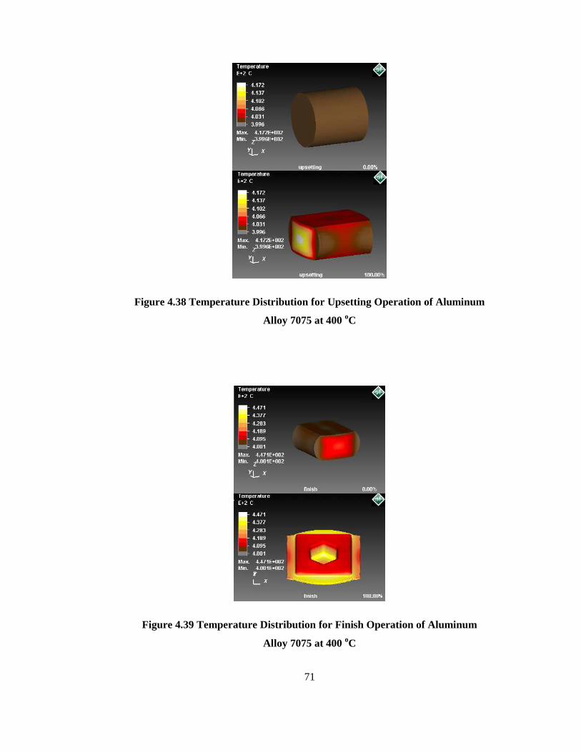
71
Figure 4.38 Temperature Distribution for Upsetting Operation of Aluminum
Alloy 7075 at 400 oC
Figure 4.39 Temperature Distribution for Finish Operation of Aluminum
Alloy 7075 at 400 oC

72
Figure 4.40 Die Force for Upsetting Operation of Aluminum Alloy 7075
at 425 oC
Figure 4.41 Die Force for Finish Operation of Aluminum Alloy 7075 at 425 oC
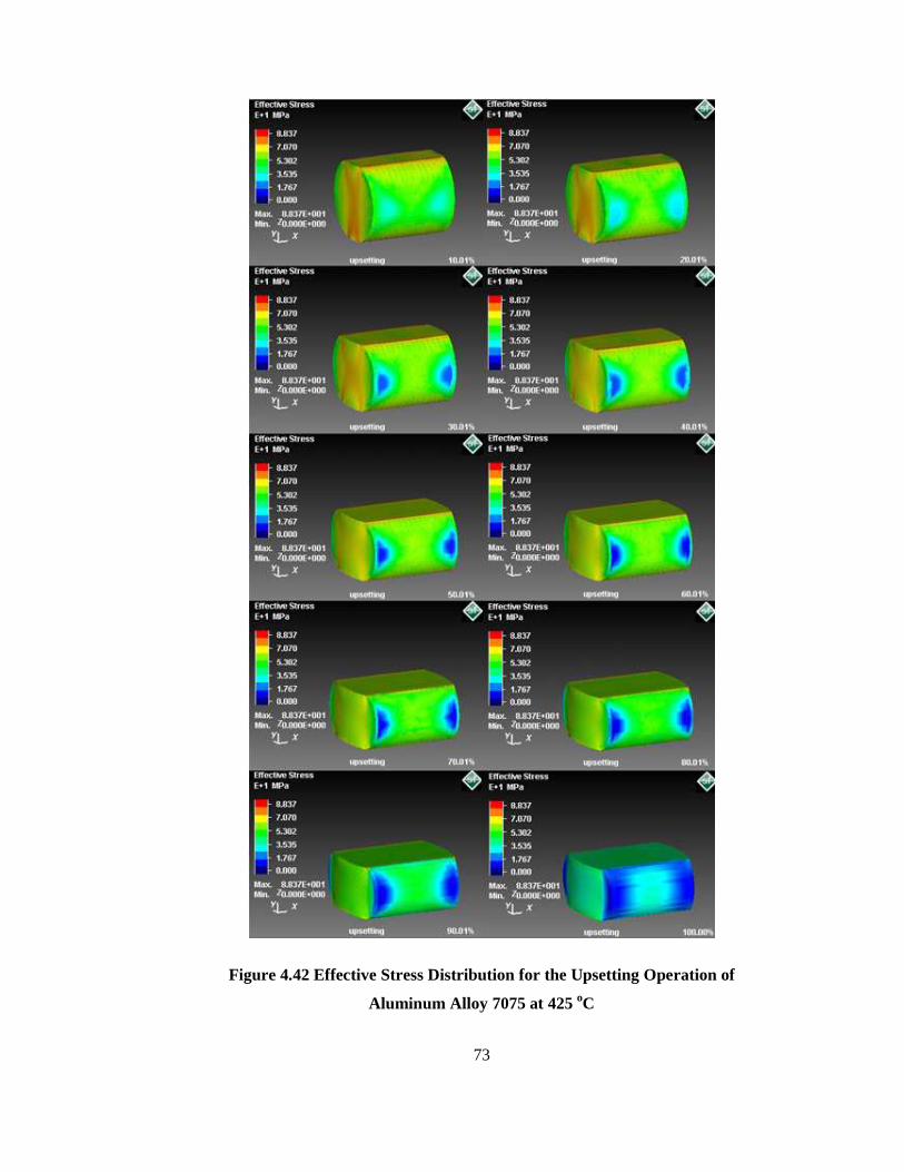
73
Figure 4.42 Effective Stress Distribution for the Upsetting Operation of
Aluminum Alloy 7075 at 425 oC
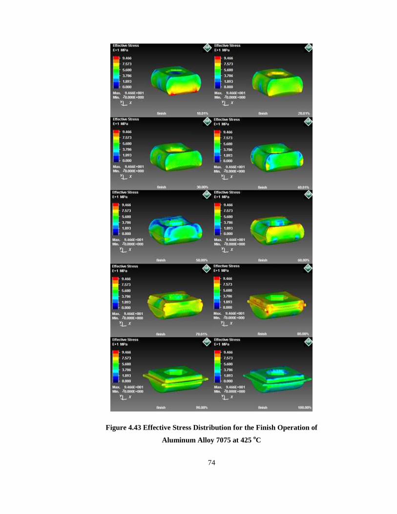
74
Figure 4.43 Effective Stress Distribution for the Finish Operation of
Aluminum Alloy 7075 at 425 oC

75
Figure 4.44 Temperature Distribution for Upsetting Operation of Aluminum
Alloy 7075 at 425 oC
Figure 4.45 Temperature Distribution for Finish Operation of Aluminum
Alloy 7075 at 425 oC

76
CHAPTER 5
MANUFACTURING OF THE FORGING DIES AND EXPERIMENTS O F ALUMINUM FORGING PROCESS
Design of the upsetting and the finish dies has been described in detailed according
to the 10 MN SMERAL mechanical press die holder geometry and; the finite volume
simulation and their results have been given in Chapter 4. In this chapter, initially
manufacturing of the upsetting and the finish dies will be mentioned and then the
experiments based on the simulation results for the 7075-0 type of aluminum alloy
will be explained with the forging equipment used during experiments.
5.1 Manufacturing of the Forging Dies
The upsetting and finish dies have been manufactured in METU-BILTIR Center
CAD/CAM Laboratory with the proper CAD/CAM approach. For the manufacturing
of the dies, "Dievar" is selected as the die material [51]. Detailed properties of the
"Dievar" are given in Appendix D. After selecting the die material, raw die materials
are turned according to the die holder dimensions and the die after the turning
operation is given in Figure 5.1.
After the turning process, MAZAK Variaxis 630-5X high-speed vertical milling
machine are used for the production of the forging dies. NC codes, e.g. G-codes, for
manufacturing of the dies are obtained by using the manufacturing module of the
PRO/ENGINEER Wildfire 3.0 [44] and then these codes are loaded to MAZAK
Variaxis 630-5X through the computer interface. After the codes are loaded to
machining center, dies are produced according G-codes and the die in the machining
process in the high-speed vertical milling machine can be seen in Figure 5.2.
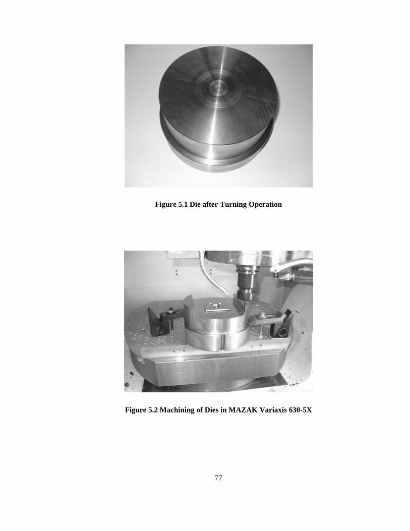
77
Figure 5.1 Die after Turning Operation
Figure 5.2 Machining of Dies in MAZAK Variaxis 630-5X

78
Views of lower finish die, upper finish die and upsetting die after machining
processes are given in Figure 5.3, Figure 5.4 and Figure 5.5 respectively.
After the production of the dies has been completed, they are sent for heat treatment.
Heat treatment should be done since high loads are applied on the die during the
forging operation and soft raw die material without heat treatment may cause failure.
Details of the heat treatment process, hardness value obtained by using the portable
hardness measuring instrument in METU-BILTIR Center Forging Research and
Application Laboratory and true stress-true strain curves for different temperatures
for the Dievar tool steel obtained after the creep experiment in the METU Central
Laboratory are given in Appendix D.
Figure 5.3 Photograph of Upper Die
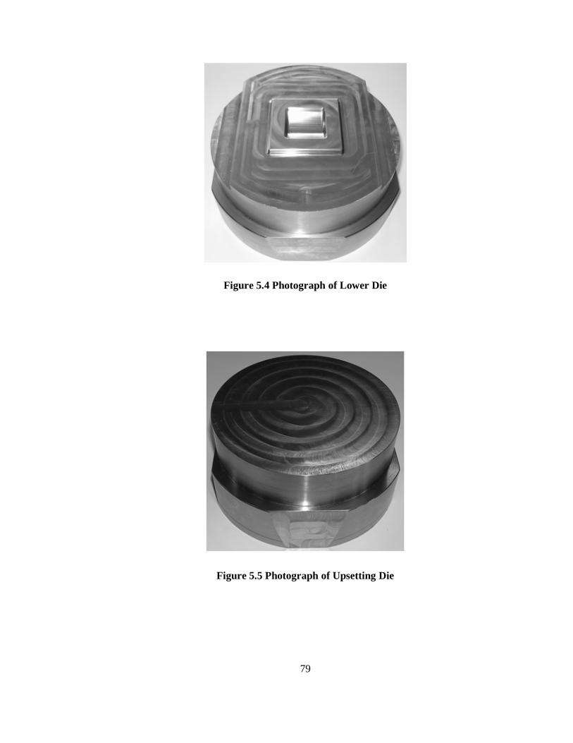
79
Figure 5.4 Photograph of Lower Die
Figure 5.5 Photograph of Upsetting Die

80
5.2 Preparation for the Experiments
Before the experiments, some preparations are made both for the experiment setup
and the initial billets. Billets are cut to the desired length in the sawing machine and
their dimensions are measured by the digital calipers and weighed by using precision
balance with the tolerance of the ± 0.01 gram as can be shown in Figure 5.6.
Figure 5.6 Photograph of Billet on Precision Balance
Dimensions of the billets and their weights before the forging process are given in
Table 5.1. In Table 5.1, some variations in the dimensions of the billet can be
observed and because of these variations also weights of the billets show variations.
Reasons of these variations are basically cutting condition of the sawing machine and
diameter variation of bought aluminum products.

81
The set up begins with the upper upsetting and the upper finish dies with the aid of
the hydraulic jack. The upper dies are raised to the desired height with the hydraulic
jack and then the upper die is aligned that the key on the die holder housing will fit
into the key way on the upper die to prevent the rotational motion. After that, the
upper dies are fastened from the front taper and back side of the die with clamping
elements and bolts. The hydraulic jack is downed and the set up of upper dies is
completed. The lower dies are also set up with the same way of the upper dies.
Lower dies are again initially aligned that the key on the die holder housing will fit
into the key way on the lower die and then mounted from the front taper and back
side of the die by using the clamping elements and bolts as can be seen from Figure
5.7. After the dies are properly set up, experimentation process begins.
Figure 5.7 Clamping of Lower Finish Die in Die Holder

82
Table 5.1 Billet Dimensions and Billet Weights
Billet No Billet Diameter
(mm)
Billet Length
(mm)
Billet Mass
(g)
1 30.03 32.06 63.30
2 29.99 32.12 63.38
3 30.06 32.21 63.70
4 30.06 32.19 63.62
5 29.99 32.12 63.38
6 30.00 32.09 62.97
7 30.05 32.01 63.07
8 30.06 32.05 63.45
9 30.10 32.20 64.19
10 30.10 32.15 63.80
11 29.95 32.40 64.29
12 29.96 32.20 63.84
13 30.00 32.01 63.20
14 30.02 32.01 63.37
15 30.02 32.10 63.46
16 29.95 32.36 64.31
17 30.05 32.16 63.95
18 30.02 32.45 64.15
19 30.04 32.15 63.76
20 30.07 32.21 64.05
21 30.04 32.39 64.39
22 30.02 32.03 63.66
23 29.96 32.25 63.88
24 30.00 32.07 62.94
25 30.03 32.10 63.48
26 30.10 32.15 63.80

83
Table 5.1 Billet Dimensions and Billet Weights (Continued)
Billet No Billet Diameter
(mm)
Billet Length
(mm)
Billet Mass
(g)
27 30.05 32.18 64.12
28 30.00 32.05 63.55
29 30.03 32.10 62.82
30 30.06 32.17 64.20
31 30.06 32.41 64.62
32 30.05 32.20 63.85
33 30.12 32.23 64.53
34 30.14 32.09 64.22
35 30.08 32.16 63.73
36 30.12 31.98 63.60
37 30.06 32.12 64.02
38 30.03 32.00 63.47
39 30.10 32.15 64.31
40 30.14 32.00 63.95
41 30.12 32.18 64.51
42 30.04 32.00 63.47
43 30.00 32.06 63.45
44 30.00 32.03 63.51
45 30.14 32.04 64.24
46 30.03 32.65 65.05
47 30.05 32.22 64.18
48 30.14 32.23 64.67
49 30.06 32.70 65.21
50 30.09 32.15 64.27
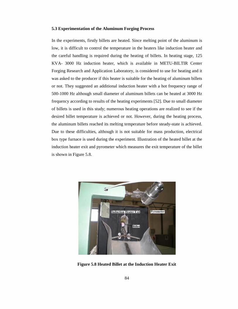
84
5.3 Experimentation of the Aluminum Forging Process
In the experiments, firstly billets are heated. Since melting point of the aluminum is
low, it is difficult to control the temperature in the heaters like induction heater and
the careful handling is required during the heating of billets. In heating stage, 125
KVA- 3000 Hz induction heater, which is available in METU-BILTIR Center
Forging Research and Application Laboratory, is considered to use for heating and it
was asked to the producer if this heater is suitable for the heating of aluminum billets
or not. They suggested an additional induction heater with a hot frequency range of
500-1000 Hz although small diameter of aluminum billets can be heated at 3000 Hz
frequency according to results of the heating experiments [52]. Due to small diameter
of billets is used in this study; numerous heating operations are realized to see if the
desired billet temperature is achieved or not. However, during the heating process,
the aluminum billets reached its melting temperature before steady-state is achieved.
Due to these difficulties, although it is not suitable for mass production, electrical
box type furnace is used during the experiment. Illustration of the heated billet at the
induction heater exit and pyrometer which measures the exit temperature of the billet
is shown in Figure 5.8.
Figure 5.8 Heated Billet at the Induction Heater Exit
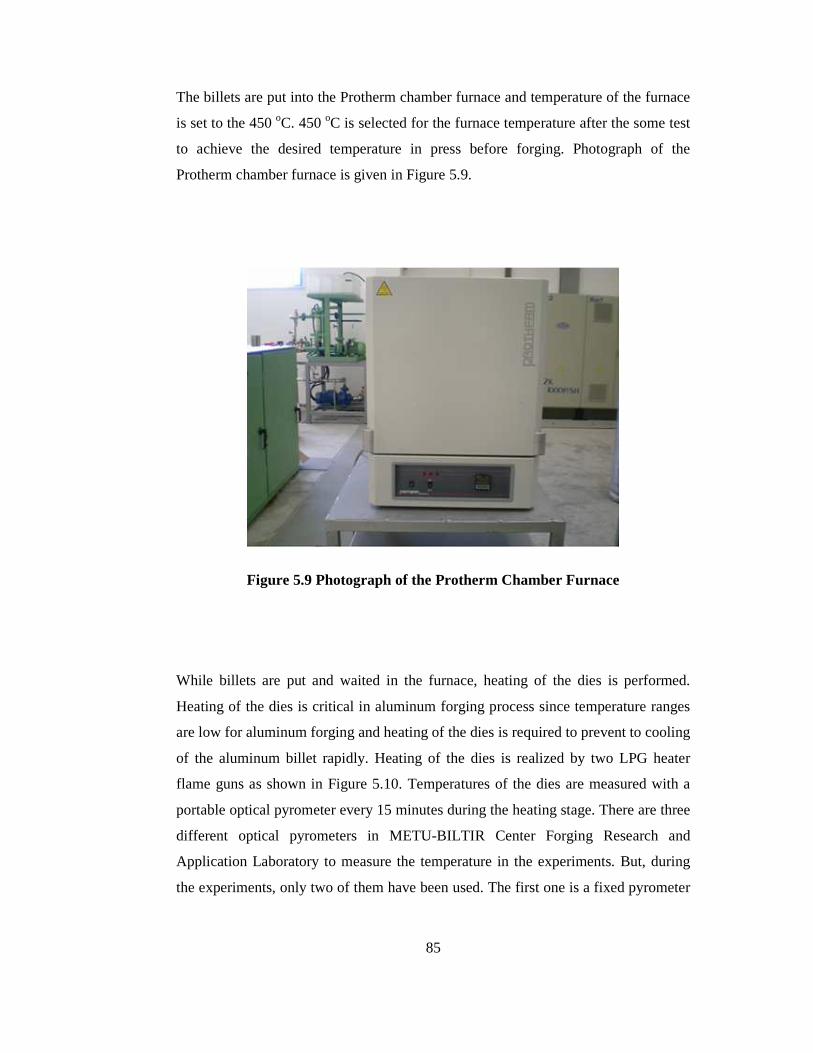
85
The billets are put into the Protherm chamber furnace and temperature of the furnace
is set to the 450 oC. 450 oC is selected for the furnace temperature after the some test
to achieve the desired temperature in press before forging. Photograph of the
Protherm chamber furnace is given in Figure 5.9.
Figure 5.9 Photograph of the Protherm Chamber Furnace
While billets are put and waited in the furnace, heating of the dies is performed.
Heating of the dies is critical in aluminum forging process since temperature ranges
are low for aluminum forging and heating of the dies is required to prevent to cooling
of the aluminum billet rapidly. Heating of the dies is realized by two LPG heater
flame guns as shown in Figure 5.10. Temperatures of the dies are measured with a
portable optical pyrometer every 15 minutes during the heating stage. There are three
different optical pyrometers in METU-BILTIR Center Forging Research and
Application Laboratory to measure the temperature in the experiments. But, during
the experiments, only two of them have been used. The first one is a fixed pyrometer
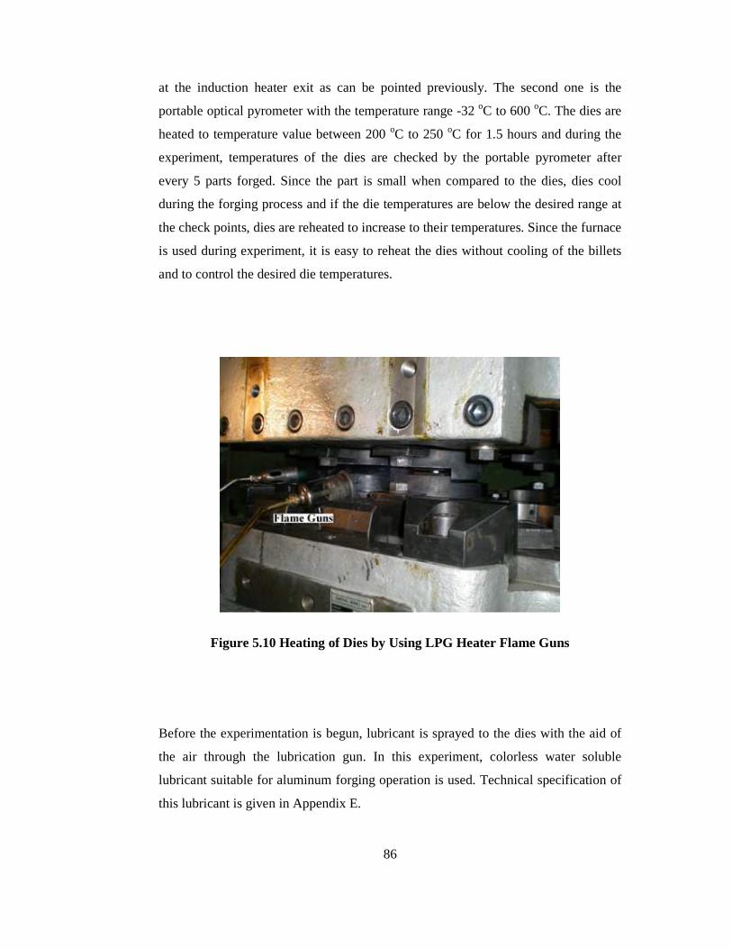
86
at the induction heater exit as can be pointed previously. The second one is the
portable optical pyrometer with the temperature range -32 oC to 600 oC. The dies are
heated to temperature value between 200 oC to 250 oC for 1.5 hours and during the
experiment, temperatures of the dies are checked by the portable pyrometer after
every 5 parts forged. Since the part is small when compared to the dies, dies cool
during the forging process and if the die temperatures are below the desired range at
the check points, dies are reheated to increase to their temperatures. Since the furnace
is used during experiment, it is easy to reheat the dies without cooling of the billets
and to control the desired die temperatures.
Figure 5.10 Heating of Dies by Using LPG Heater Flame Guns
Before the experimentation is begun, lubricant is sprayed to the dies with the aid of
the air through the lubrication gun. In this experiment, colorless water soluble
lubricant suitable for aluminum forging operation is used. Technical specification of
this lubricant is given in Appendix E.

87
During the experiments, firstly single stage forging process is realized to verify the
folds formation for single stroke operation in the finite volume simulations. In
Figure 5.11, the fold formation obtained during experiment for the single stroke
operation is shown. As seen from the figure, fold is at the half of the hexagonal hole
like a line while at the corner of the hexagonal hole, it grows in volume. The fold
formation in Figure 5.11 shows that it is necessary the make two stage operations. As
a result, finite volume simulation gives very similar result with the experiments and
finite volume programs are very suitable to predict the forging stages and forging
behavior of the required operations.
Figure 5.11 Fold Formation for Single Stroke Forging Operation
From Figure 5.12 to Figure 5.16, forging stages of the parts are given for the two
stages forging operations. Billet is taken from the furnace and placed onto the
upsetting die and after upsetting is completed, the finish operation is applied and
finally parts are obtained as given in Figure 5.16.

88
Figure 5.12 A View of Heated Billet in the Furnace
Figure 5.13 A View of Heated Billet on the Upsetting Die
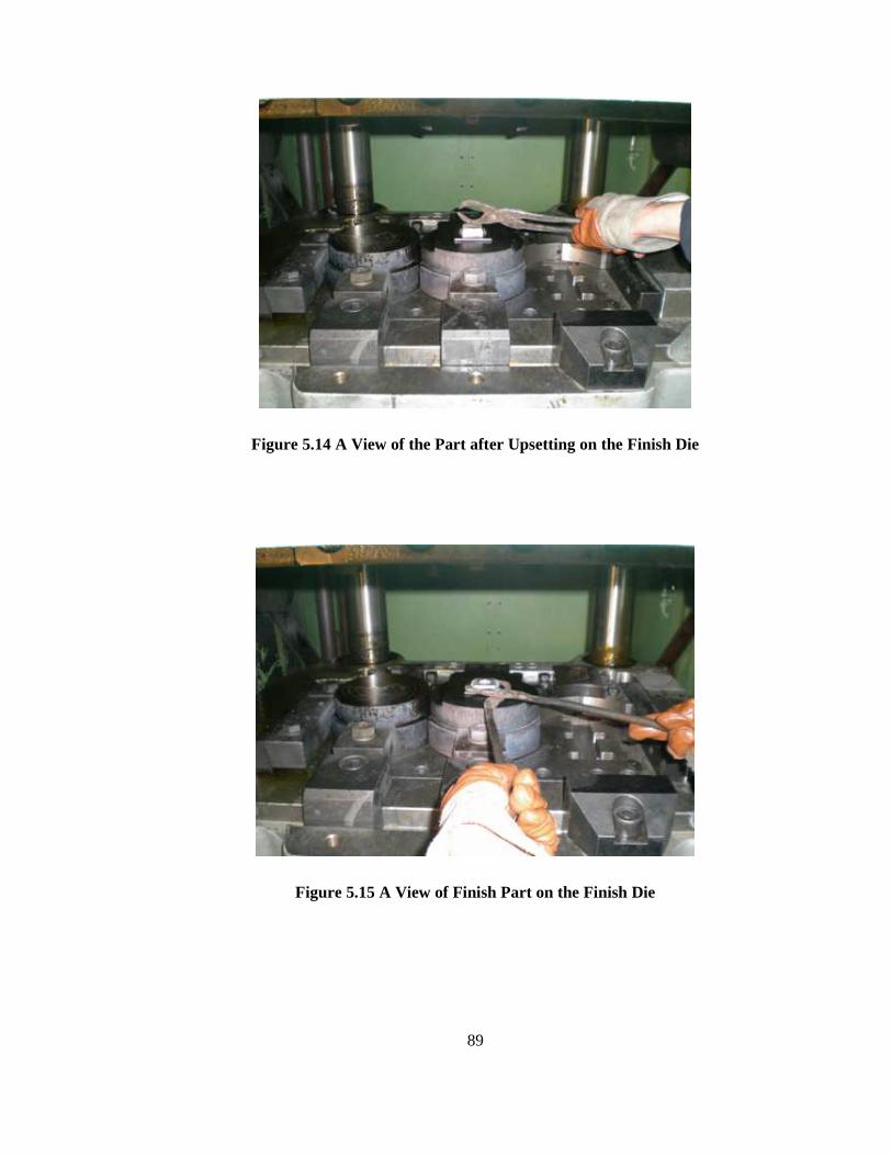
89
Figure 5.14 A View of the Part after Upsetting on the Finish Die
Figure 5.15 A View of Finish Part on the Finish Die

90
Figure 5.16 Views of Finish Parts
5.4 Results for the Experiment
During the experiments, the billet temperature before upsetting, part temperature
after upsetting that is before finish and part temperature after finish are measured and
tabulated. The die temperatures are also measured for every 5 parts to keep the die
temperatures within the desired range. The data recorded during the experiment is
given in Table 5.2. Furthermore, the forging part mass measured by precision
balance to see if there is any scale formation or not after forging is cleaned, its
dimensions and flash thickness are measured by using the digital calipers after the
forging operation and its values are tabulated in Table 5.3.

91
Table 5.2 Experimental Data Recorded during Forging Process
Billet No
Billet Temperature
Before
Upsetting
(oC)
Part Temperature
After
Upsetting
(oC)
Part Temperature
After
Finish Forging
(oC)
1 390 420 441
2 395 430 460
3 404 425 434
4 408 435 450
5 392 420 467
6 375 402 436
7 393 420 436
8 385 420 435
9 405 433 445
10 410 425 435
11 370 392 401
12 365 384 391
13 383 409 454
14 415 422 467
15 402 427 448
16 383 417 445
17 387 417 440
18 389 402 437
19 401 421 434
20 370 385 410
21 405 420 445
22 396 409 440
23 375 390 415
24 402 415 440
25 396 420 455

92
Table 5.2 Experimental Data Recorded during Forging Process (Continued)
Billet No
Billet Temperature
Before
Upsetting
(oC)
Part Temperature
After
Upsetting
(oC)
Part Temperature
After
Finish Forging
(oC)
26 380 413 423
27 370 392 420
28 407 425 440
29 405 420 447
30 405 425 456
31 396 424 460
32 397 429 455
33 391 425 463
34 408 421 439
35 397 410 426
36 396 412 430
37 402 416 430
38 395 405 435
39 393 407 442
40 412 427 438
41 382 396 425
42 410 425 460
43 403 417 455
44 401 411 463
45 389 401 439
46 403 417 443
47 410 416 435
48 396 410 429
49 404 414 422
50 400 423 445

93
Table 5.3 Experimental Data Measured after the Forging Process
Billet
No
Part
Mass
(g)
Height
(mm)
Length
(mm)
Width
(mm)
Hexagonal
Cavity
Height
(mm)
Hexagonal
Cavity
Length
(mm)
Flash
Thickness
(mm)
1 63.29 18.05 40.07 40.07 11.98 18.97 1.86
2 63.36 18.04 40.09 40.08 11.97 19.05 1.82
3 63.70 18.05 39.98 39.97 11.97 19.04 1.81
4 63.62 18.17 40.08 40.08 12.00 18.98 1.90
5 63.36 18.12 40.20 40.18 12.04 19.08 1.88
6 62.97 18.01 40.07 40.07 12.02 19.08 1.80
7 63.06 18.15 40.12 40.12 11.98 19.13 1.88
8 63.44 18.00 39.98 39.98 12.01 19.01 1.82
9 64.15 18.19 40.09 40.09 11.98 19.14 1.88
10 63.80 18.33 40.22 40.22 12.07 19.07 1.95
11 64.27 18.09 40.05 40.05 11.98 19.02 1.81
12 63.84 18.05 40.09 40.09 11.97 19.05 1.84
13 63.19 17.95 40.05 40.05 12.03 19.01 1.76
14 63.37 18.05 40.07 40.07 11.90 19.10 1.85
15 63.44 18.07 40.06 40.07 11.96 19.05 1.86
16 64.31 18.05 40.04 40.01 12.01 19.02 1.83
17 63.90 18.07 39.97 39.99 11.95 18.95 1.85
18 64.12 18.12 40.04 40.08 12.07 19.05 1.87
19 63.75 18.25 40.00 40.00 11.94 19.03 1.94
20 64.03 18.01 39.98 39.98 11.99 19.01 1.79
21 64.36 18.18 40.11 40.11 12.03 19.12 1.96
22 63.66 18.09 40.07 40.07 12.05 19.07 1.88
23 63.88 18.04 40.01 40.01 11.95 19.01 1.82
24 62.93 18.31 40.03 40.03 12.07 18.95 2.01
25 63.48 17.99 40.02 40.02 12.01 18.99 1.79
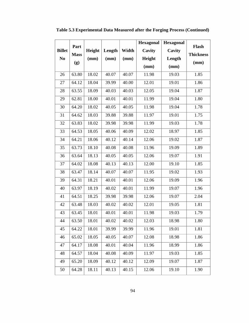
94
Table 5.3 Experimental Data Measured after the Forging Process (Continued)
Billet
No
Part
Mass
(g)
Height
(mm)
Length
(mm)
Width
(mm)
Hexagonal
Cavity
Height
(mm)
Hexagonal
Cavity
Length
(mm)
Flash
Thickness
(mm)
26 63.80 18.02 40.07 40.07 11.98 19.03 1.85
27 64.12 18.04 39.99 40.00 12.01 19.01 1.86
28 63.55 18.09 40.03 40.03 12.05 19.04 1.87
29 62.81 18.00 40.01 40.01 11.99 19.04 1.80
30 64.20 18.02 40.05 40.05 11.98 19.04 1.78
31 64.62 18.03 39.88 39.88 11.97 19.01 1.75
32 63.83 18.02 39.98 39.98 11.99 19.03 1.78
33 64.53 18.05 40.06 40.09 12.02 18.97 1.85
34 64.21 18.06 40.12 40.14 12.06 19.02 1.87
35 63.73 18.10 40.08 40.08 11.96 19.09 1.89
36 63.64 18.13 40.05 40.05 12.06 19.07 1.91
37 64.02 18.08 40.13 40.13 12.00 19.10 1.85
38 63.47 18.14 40.07 40.07 11.95 19.02 1.93
39 64.31 18.21 40.01 40.01 12.06 19.09 1.96
40 63.97 18.19 40.02 40.01 11.99 19.07 1.96
41 64.51 18.25 39.98 39.98 12.06 19.07 2.04
42 63.48 18.03 40.02 40.02 12.01 19.05 1.81
43 63.45 18.01 40.01 40.01 11.98 19.03 1.79
44 63.50 18.01 40.02 40.02 12.03 18.98 1.80
45 64.22 18.01 39.99 39.99 11.96 19.01 1.81
46 65.02 18.05 40.05 40.07 12.08 18.98 1.86
47 64.17 18.08 40.01 40.04 11.96 18.99 1.86
48 64.57 18.04 40.08 40.09 11.97 19.03 1.85
49 65.20 18.09 40.12 40.12 12.09 19.07 1.87
50 64.28 18.11 40.13 40.15 12.06 19.10 1.90
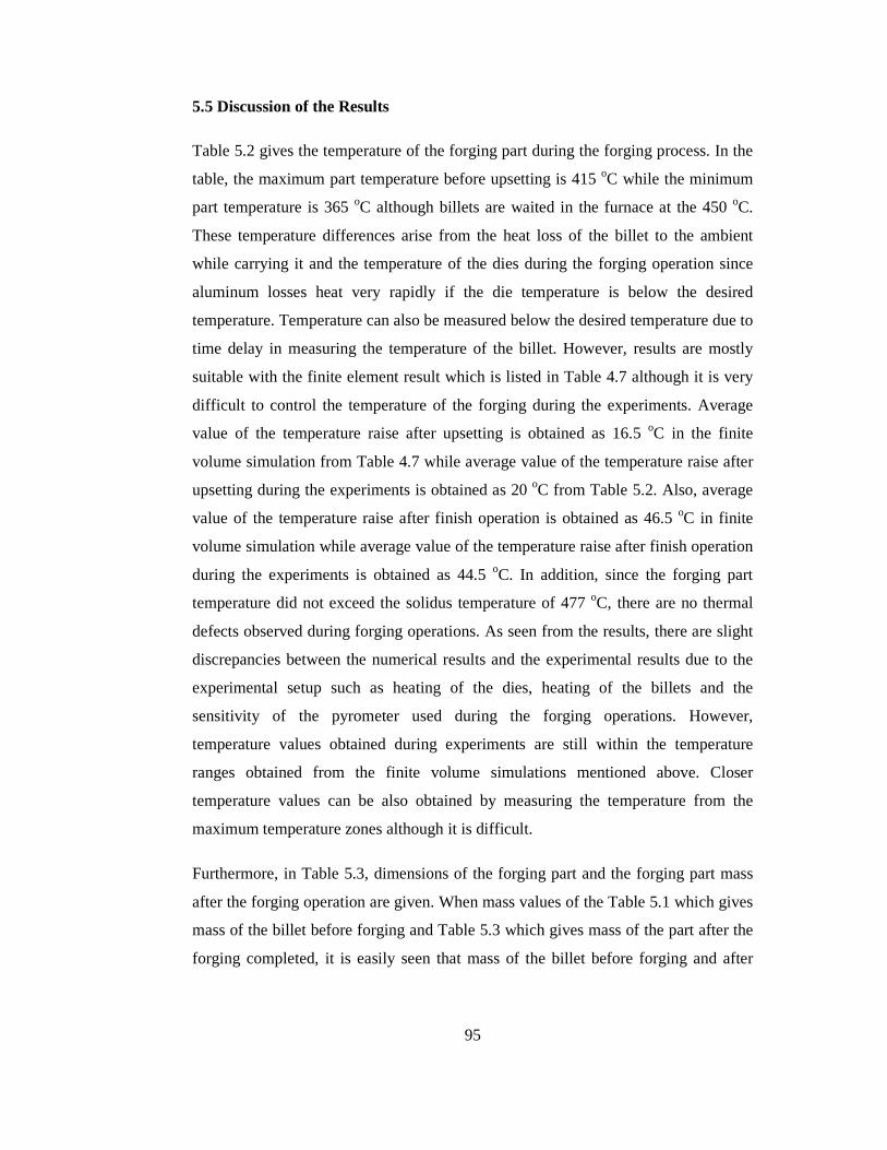
95
5.5 Discussion of the Results
Table 5.2 gives the temperature of the forging part during the forging process. In the
table, the maximum part temperature before upsetting is 415 oC while the minimum
part temperature is 365 oC although billets are waited in the furnace at the 450 oC.
These temperature differences arise from the heat loss of the billet to the ambient
while carrying it and the temperature of the dies during the forging operation since
aluminum losses heat very rapidly if the die temperature is below the desired
temperature. Temperature can also be measured below the desired temperature due to
time delay in measuring the temperature of the billet. However, results are mostly
suitable with the finite element result which is listed in Table 4.7 although it is very
difficult to control the temperature of the forging during the experiments. Average
value of the temperature raise after upsetting is obtained as 16.5 oC in the finite
volume simulation from Table 4.7 while average value of the temperature raise after
upsetting during the experiments is obtained as 20 oC from Table 5.2. Also, average
value of the temperature raise after finish operation is obtained as 46.5 oC in finite
volume simulation while average value of the temperature raise after finish operation
during the experiments is obtained as 44.5 oC. In addition, since the forging part
temperature did not exceed the solidus temperature of 477 oC, there are no thermal
defects observed during forging operations. As seen from the results, there are slight
discrepancies between the numerical results and the experimental results due to the
experimental setup such as heating of the dies, heating of the billets and the
sensitivity of the pyrometer used during the forging operations. However,
temperature values obtained during experiments are still within the temperature
ranges obtained from the finite volume simulations mentioned above. Closer
temperature values can be also obtained by measuring the temperature from the
maximum temperature zones although it is difficult.
Furthermore, in Table 5.3, dimensions of the forging part and the forging part mass
after the forging operation are given. When mass values of the Table 5.1 which gives
mass of the billet before forging and Table 5.3 which gives mass of the part after the
forging completed, it is easily seen that mass of the billet before forging and after

96
forging are the same for the majority of the part. From the result of the mass of the
billet before forging and part mass after forging, it can be concluded that there is no
scale formation for the aluminum forging.
Figure 5.17 Forged Part Obtained in the Experiment
Additionally, dimensions of the forged part shown in Figure 5.17 according to Figure
5.18 are given in Table 5.3. Dimensions of the part are given as 40 mm for the length
and width and 18 mm for the height with the ± 0.5 mm tolerances from the technical
drawing of the part in Appendix A. From Table 5.3, the maximum width and length
are measured as 40.22 mm while the minimum value is 39.88 mm and part height is
between 18.33 mm and 17.95 mm. These dimensions are within the recommended
tolerance limits. Also, hexagonal cavity height and length are 12 mm and 19 mm
from the technical drawing of the part in Appendix A, respectively. During the
experiments, the hexagonal cavity height is obtained between 11.90 mm and 12.09
mm and hexagonal length is obtained between 18.95 mm and 19.14 mm in the
required tolerance values. On the other hand, the flash thickness is measured between
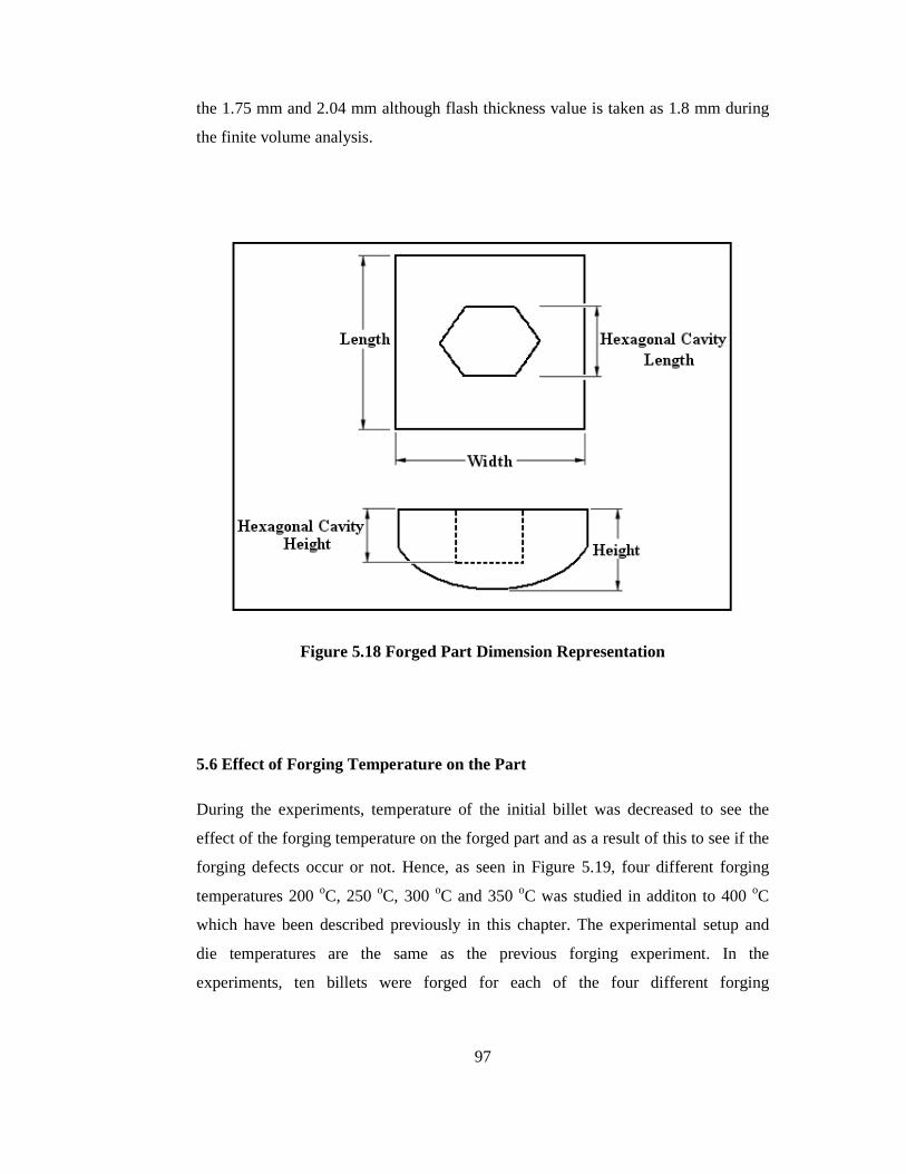
97
the 1.75 mm and 2.04 mm although flash thickness value is taken as 1.8 mm during
the finite volume analysis.
Figure 5.18 Forged Part Dimension Representation
5.6 Effect of Forging Temperature on the Part
During the experiments, temperature of the initial billet was decreased to see the
effect of the forging temperature on the forged part and as a result of this to see if the
forging defects occur or not. Hence, as seen in Figure 5.19, four different forging
temperatures 200 oC, 250 oC, 300 oC and 350 oC was studied in additon to 400 oC
which have been described previously in this chapter. The experimental setup and
die temperatures are the same as the previous forging experiment. In the
experiments, ten billets were forged for each of the four different forging
98
temperatures; and the experimental data recorded before the forging operation and
after the forging operation are provided in Appendix F.
Figure 5.19 Forged Part Obtained in the Experiment for Different Forging
Temperatures
In the experiments, the forging temperature was firstly decreased to the 350 oC and
there was no forging defects observed at this temperature for the ten different part
forged. Thus, the forging temperature was decreased to the 300 oC and forging
operation was completed at this temperature and at the end of the forging operation
crack formation were seen in the two forgings. The crack were occured in the flash
zone as seen in Figure 5.20. Therefore, the billet temperature of 300 oC can be
practically applicable for this particular part geometry. The forging temperature was
decreased to the 250 oC and it was observed that defected part numbers became three
and the cracks were observed in the flash zone of the forgings. Although at this time
the cracks observed were greater in length than as in the 300 oC as seen in Figure
5.21, the billet temperature of 250 oC can still be applicable for this particular part
geometry. Finally, the experiments were realized in 200 oC and four parts had
defects. As seen in Figure 5.22, the cracks were formed increasingly also in the flash
zone of the forgings in this temperature.

99
Figure 5.20 Crack Observation in the Flash Zone for the Forging Temperature
of 300 oC
Figure 5.21 Crack Observation in the Flash Zone for the Forging Temperature
of 250 oC

100
Figure 5.22 Crack Observation in the Flash Zone for the Forging Temperature
of 200 oC
The cracks were occurred in the flash zones of the forgings for the forging
temperatures of 200 oC, 250 oC and 300 oC as seen in the results. Although these
temperatures can be suitable for this particular part geometry, they can be critical for
the different part geometries,and careful handling can be required during forging
process for the different part geometries.
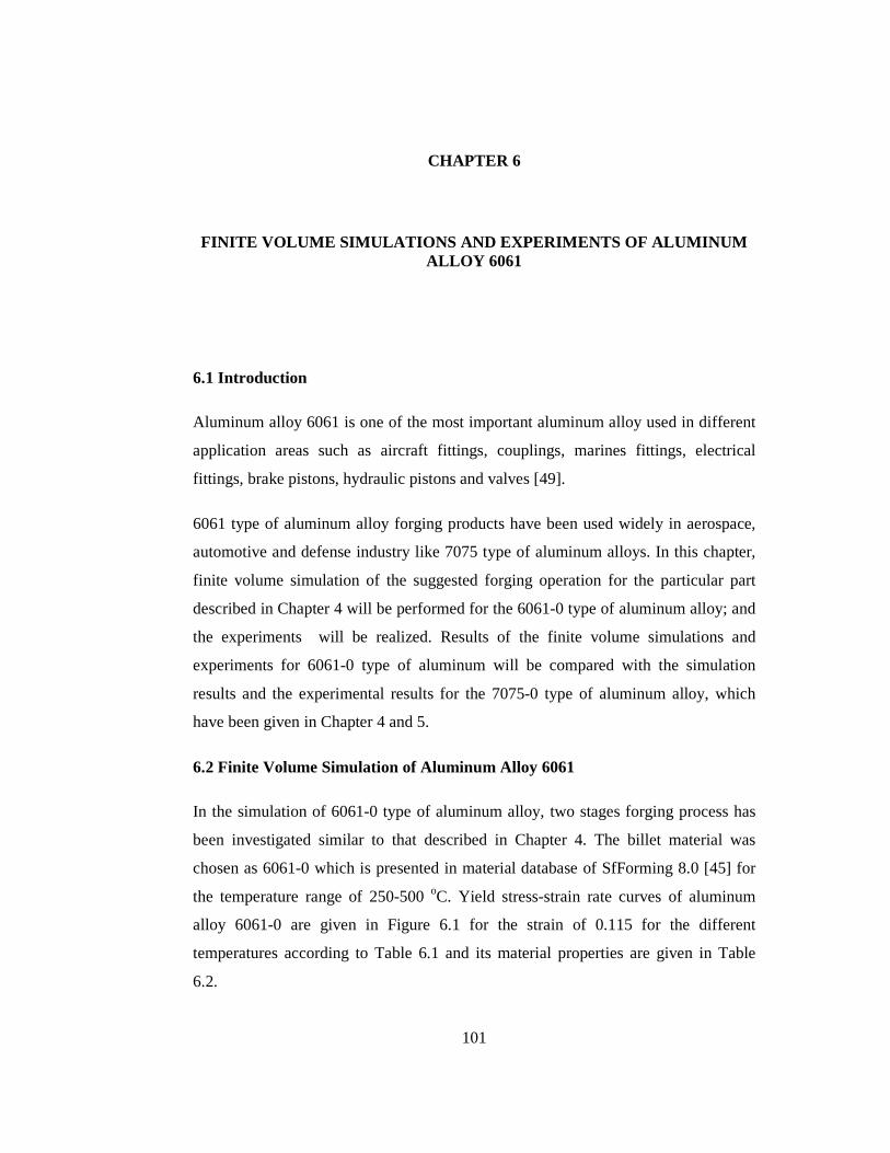
101
CHAPTER 6
FINITE VOLUME SIMULATIONS AND EXPERIMENTS OF ALUMIN UM ALLOY 6061
6.1 Introduction
Aluminum alloy 6061 is one of the most important aluminum alloy used in different
application areas such as aircraft fittings, couplings, marines fittings, electrical
fittings, brake pistons, hydraulic pistons and valves [49].
6061 type of aluminum alloy forging products have been used widely in aerospace,
automotive and defense industry like 7075 type of aluminum alloys. In this chapter,
finite volume simulation of the suggested forging operation for the particular part
described in Chapter 4 will be performed for the 6061-0 type of aluminum alloy; and
the experiments will be realized. Results of the finite volume simulations and
experiments for 6061-0 type of aluminum will be compared with the simulation
results and the experimental results for the 7075-0 type of aluminum alloy, which
have been given in Chapter 4 and 5.
6.2 Finite Volume Simulation of Aluminum Alloy 6061
In the simulation of 6061-0 type of aluminum alloy, two stages forging process has
been investigated similar to that described in Chapter 4. The billet material was
chosen as 6061-0 which is presented in material database of SfForming 8.0 [45] for
the temperature range of 250-500 oC. Yield stress-strain rate curves of aluminum
alloy 6061-0 are given in Figure 6.1 for the strain of 0.115 for the different
temperatures according to Table 6.1 and its material properties are given in Table
6.2.
102
The tensile yield strength and the ultimate tensile strength of the aluminum alloy
6061-0 are given in Equation 6.1 and Equation 6.2 according to the simple tension
test at the room temperature [49]. These values are fairly below the tensile yield
strength and the ultimate tensile strength values of aluminum alloy 7075-0 given in
Chapter 4.
=Yσ 55.2 MPa (6.1)
=UTSσ 124 MPa (6.2)
In the simulation process, forging dies, the billet dimensions and the forming
properties were used same as in Chapter 4. Initial temperature of the billet is taken as
200 oC, 250 oC, 300 oC, 350 oC and 400 oC. Initial temperature of the dies is assumed
as 200 °C and the plastic shear friction is 0.2.
Table 6.1 Flow Stress Parameters for 6061-0 [45]
Yield Stress according to Temperature Strain Rate
(1/s) 250 oC 300 oC 350 oC 400 oC 450 oC 500 oC
0.01 60.24 47.75 37.85 29.99 23.77 18.84
0.34 89.77 71.16 56.41 44.70 35.42 28.08
0.67 96.95 76.84 60.90 48.27 38.26 30.32
1.00 101.44 80.39 63.73 50.50 40.04 31.72

103
Figure 6.1 Stress-Strain Rate Curves of 6061-0 for Different Temperatures [45]
Table 6.2 Material Properties of 6061-0 [45]
Material Property Value
Young's Modulus (GPa) 36.81
Poisson's Ratio 0.333
Density (kg/m3) 2640
Thermal Conductivity (Watt/(m*K)) 193
Specific Heat Constant (Joule/(kg*K)) 1132
Coefficient of Thermal Expansion (1/K) 2.8e-5
Solidus Point (oC) 582
Melting Point (oC) 652
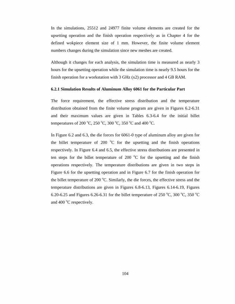
104
In the simulations, 25512 and 24977 finite volume elements are created for the
upsetting operation and the finish operation respectively as in Chapter 4 for the
defined wokpiece element size of 1 mm. However, the finite volume element
numbers changes during the simulation since new meshes are created.
Although it changes for each analysis, the simulation time is measured as nearly 3
hours for the upsetting operation while the simulation time is nearly 9.5 hours for the
finish operation for a workstation with 3 GHz (x2) processor and 4 GB RAM.
6.2.1 Simulation Results of Aluminum Alloy 6061 for the Particular Part
The force requirement, the effective stress distribution and the temperature
distribution obtained from the finite volume program are given in Figures 6.2-6.31
and their maximum values are given in Tables 6.3-6.4 for the initial billet
temperatures of 200 oC, 250 oC, 300 oC, 350 oC and 400 oC.
In Figure 6.2 and 6.3, the die forces for 6061-0 type of aluminum alloy are given for
the billet temperature of 200 oC for the upsetting and the finish operations
respectively. In Figure 6.4 and 6.5, the effective stress distributions are presented in
ten steps for the billet temperature of 200 oC for the upsetting and the finish
operations respectively. The temperature distributions are given in two steps in
Figure 6.6 for the upsetting operation and in Figure 6.7 for the finish operation for
the billet temperature of 200 oC. Similarly, the die forces, the effective stress and the
temperature distributions are given in Figures 6.8-6.13, Figures 6.14-6.19, Figures
6.20-6.25 and Figures 6.26-6.31 for the billet temperature of 250 oC, 300 oC, 350 oC
and 400 oC respectively.
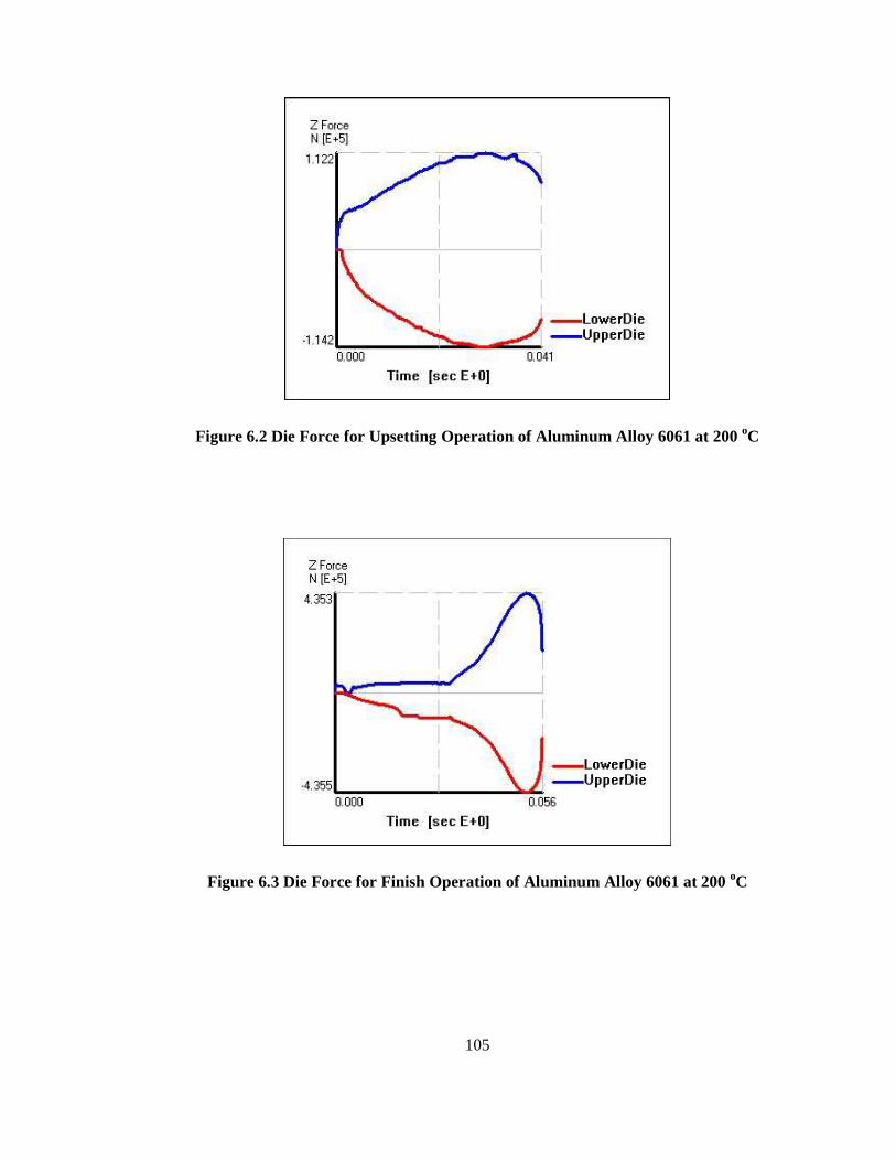
105
Figure 6.2 Die Force for Upsetting Operation of Aluminum Alloy 6061 at 200 oC
Figure 6.3 Die Force for Finish Operation of Aluminum Alloy 6061 at 200 oC

106
Figure 6.4 Effective Stress Distribution for the Upsetting Operation of
Aluminum Alloy 6061 at 200 oC
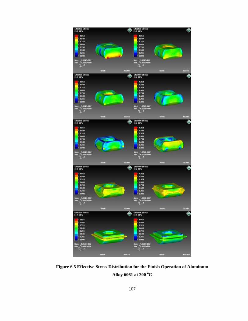
107
Figure 6.5 Effective Stress Distribution for the Finish Operation of Aluminum
Alloy 6061 at 200 oC

108
Figure 6.6 Temperature Distribution for Upsetting Operation of Aluminum
Alloy 6061 at 200 oC
Figure 6.7 Temperature Distribution for Finish Operation of Aluminum Alloy
6061 at 200 oC
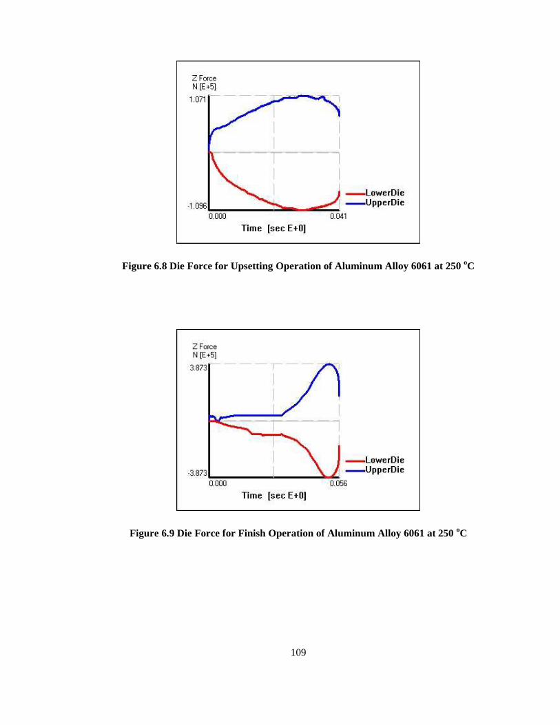
109
Figure 6.8 Die Force for Upsetting Operation of Aluminum Alloy 6061 at 250 oC
Figure 6.9 Die Force for Finish Operation of Aluminum Alloy 6061 at 250 oC

110
Figure 6.10 Effective Stress Distribution for the Upsetting Operation of
Aluminum Alloy 6061 at 250 oC
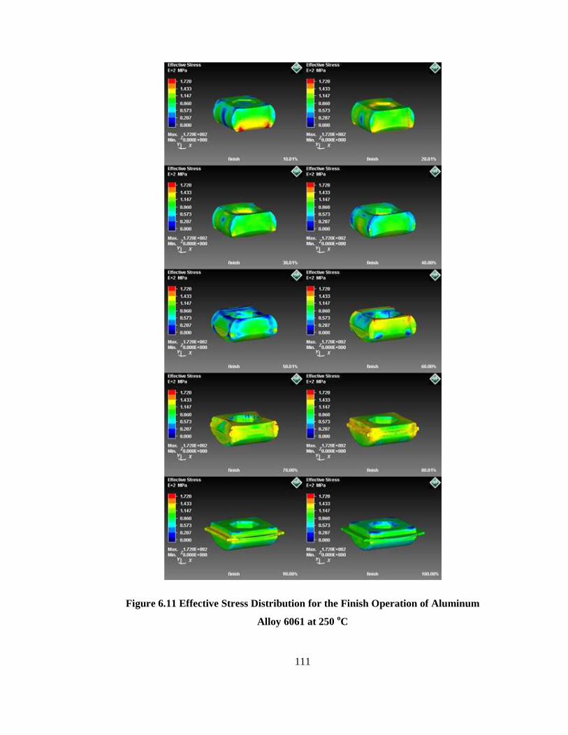
111
Figure 6.11 Effective Stress Distribution for the Finish Operation of Aluminum
Alloy 6061 at 250 oC
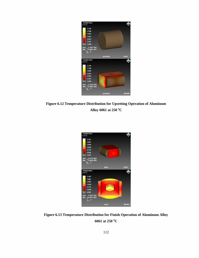
112
Figure 6.12 Temperature Distribution for Upsetting Operation of Aluminum
Alloy 6061 at 250 oC
Figure 6.13 Temperature Distribution for Finish Operation of Aluminum Alloy
6061 at 250 oC

113
Figure 6.14 Die Force for Upsetting Operation of Aluminum Alloy 6061
at 300 oC
Figure 6.15 Die Force for Finish Operation of Aluminum Alloy 6061 at 300 oC

114
Figure 6.16 Effective Stress Distribution for the Upsetting Operation of
Aluminum Alloy 6061 at 300 oC

115
Figure 6.17 Effective Stress Distribution for the Finish Operation of Aluminum
Alloy 6061 at 300 oC

116
Figure 6.18 Temperature Distribution for Upsetting Operation of Aluminum
Alloy 6061 at 300 oC
Figure 6.19 Temperature Distribution for Finish Operation of Aluminum Alloy
6061 at 300 oC
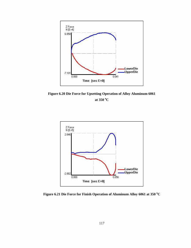
117
Figure 6.20 Die Force for Upsetting Operation of Alloy Aluminum 6061
at 350 oC
Figure 6.21 Die Force for Finish Operation of Aluminum Alloy 6061 at 350 oC
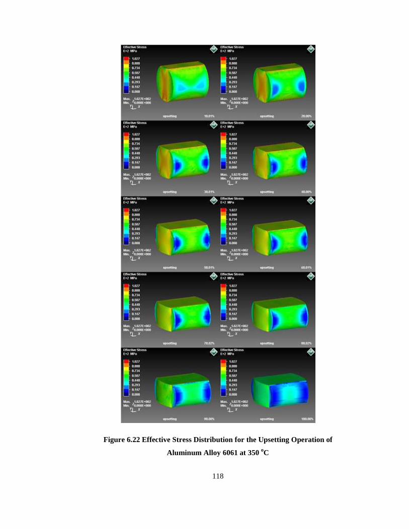
118
Figure 6.22 Effective Stress Distribution for the Upsetting Operation of
Aluminum Alloy 6061 at 350 oC

119
Figure 6.23 Effective Stress Distribution for the Finish Operation of Aluminum
Alloy 6061 at 350 oC
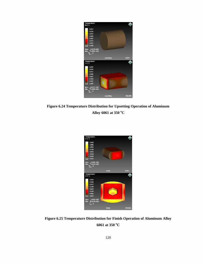
120
Figure 6.24 Temperature Distribution for Upsetting Operation of Aluminum
Alloy 6061 at 350 oC
Figure 6.25 Temperature Distribution for Finish Operation of Aluminum Alloy
6061 at 350 oC
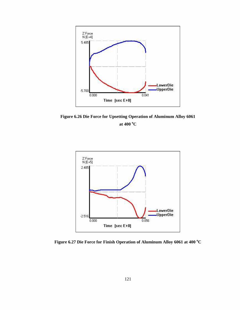
121
Figure 6.26 Die Force for Upsetting Operation of Aluminum Alloy 6061
at 400 oC
Figure 6.27 Die Force for Finish Operation of Aluminum Alloy 6061 at 400 oC

122
Figure 6.28 Effective Stress Distribution for the Upsetting Operation of
Aluminum Alloy 6061 at 400 oC

123
Figure 6.29 Effective Stress Distribution for the Finish Operation of Aluminum
Alloy 6061 at 400 oC
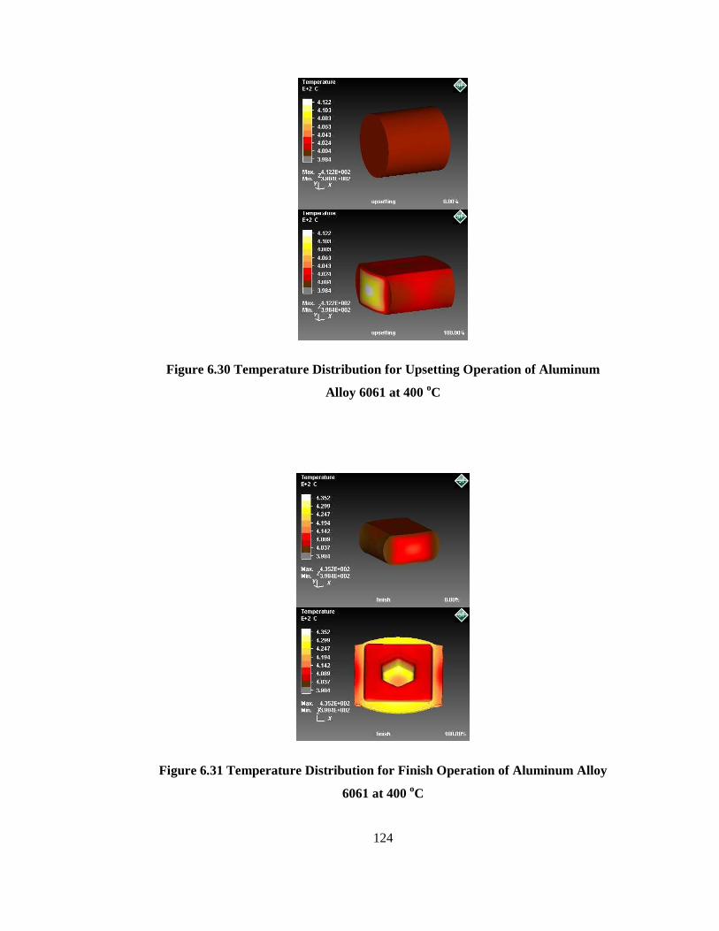
124
Figure 6.30 Temperature Distribution for Upsetting Operation of Aluminum
Alloy 6061 at 400 oC
Figure 6.31 Temperature Distribution for Finish Operation of Aluminum Alloy
6061 at 400 oC
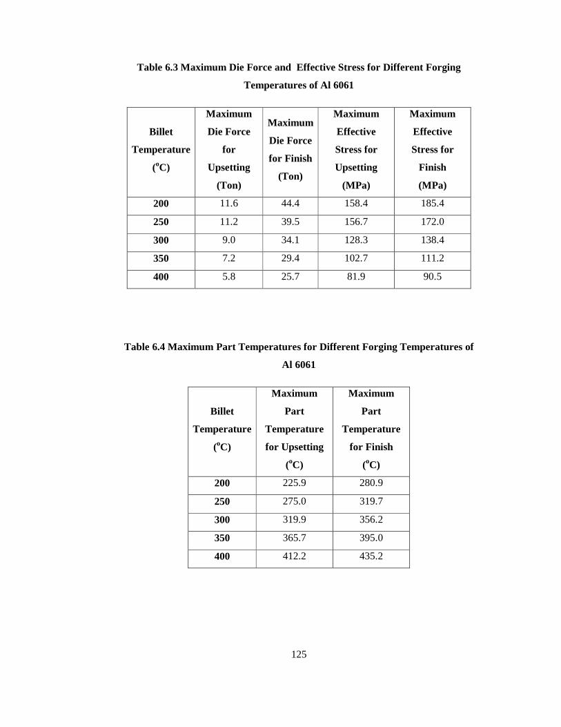
125
Table 6.3 Maximum Die Force and Effective Stress for Different Forging
Temperatures of Al 6061
Billet
Temperature
(oC)
Maximum
Die Force
for
Upsetting
(Ton)
Maximum
Die Force
for Finish
(Ton)
Maximum
Effective
Stress for
Upsetting
(MPa)
Maximum
Effective
Stress for
Finish
(MPa)
200 11.6 44.4 158.4 185.4
250 11.2 39.5 156.7 172.0
300 9.0 34.1 128.3 138.4
350 7.2 29.4 102.7 111.2
400 5.8 25.7 81.9 90.5
Table 6.4 Maximum Part Temperatures for Different Forging Temperatures of
Al 6061
Billet
Temperature
(oC)
Maximum
Part
Temperature
for Upsetting
(oC)
Maximum
Part
Temperature
for Finish
(oC)
200 225.9 280.9
250 275.0 319.7
300 319.9 356.2
350 365.7 395.0
400 412.2 435.2
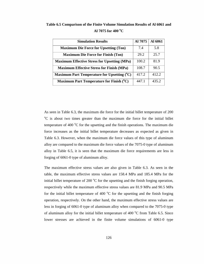
126
Table 6.5 Comparison of the Finite Volume Simulation Results of Al 6061 and
Al 7075 for 400 oC
Simulation Results Al 7075 Al 6061
Maximum Die Force for Upsetting (Ton) 7.4 5.8
Maximum Die Force for Finish (Ton) 29.2 25.7
Maximum Effective Stress for Upsetting (MPa) 100.2 81.9
Maximum Effective Stress for Finish (MPa) 108.7 90.5
Maximum Part Temperature for Upsetting (oC) 417.2 412.2
Maximum Part Temperature for Finish (oC) 447.1 435.2
As seen in Table 6.3, the maximum die force for the initial billet temperature of 200 oC is about two times greater than the maximum die force for the initial billet
temperature of 400 oC for the upsetting and the finish operations. The maximum die
force increases as the initial billet temperature decreases as expected as given in
Table 6.3. However, when the maximum die force values of this type of aluminum
alloy are compared to the maximum die force values of the 7075-0 type of aluminum
alloy in Table 6.5, it is seen that the maximum die force requirements are less in
forging of 6061-0 type of aluminum alloy.
The maximum effective stress values are also given in Table 6.3. As seen in the
table, the maximum effective stress values are 158.4 MPa and 185.4 MPa for the
initial billet temperature of 200 oC for the upsetting and the finish forging operation,
respectively while the maximum effective stress values are 81.9 MPa and 90.5 MPa
for the initial billet temperature of 400 oC for the upsetting and the finish forging
operation, respectively. On the other hand, the maximum effective stress values are
less in forging of 6061-0 type of aluminum alloy when compared to the 7075-0 type
of aluminum alloy for the initial billet temperature of 400 oC from Table 6.5. Since
lower stresses are achieved in the finite volume simulations of 6061-0 type
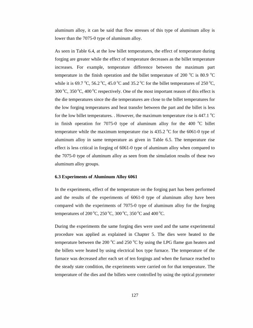
127
aluminum alloy, it can be said that flow stresses of this type of aluminum alloy is
lower than the 7075-0 type of aluminum alloy.
As seen in Table 6.4, at the low billet temperatures, the effect of temperature during
forging are greater while the effect of temperature decreases as the billet temperature
increases. For example, temperature difference between the maximum part
temperature in the finish operation and the billet temperature of 200 oC is 80.9 oC
while it is 69.7 oC, 56.2 oC, 45.0 oC and 35.2 oC for the billet temperatures of 250 oC,
300 oC, 350 oC, 400 oC respectively. One of the most important reason of this effect is
the die temperatures since the die temperatures are close to the billet temperatures for
the low forging temperatures and heat transfer between the part and the billet is less
for the low billet temperatures. . However, the maximum temperature rise is 447.1 oC
in finish operation for 7075-0 type of aluminum alloy for the 400 oC billet
temperature while the maximum temperature rise is 435.2 oC for the 6061-0 type of
aluminum alloy in same temperature as given in Table 6.5. The temperature rise
effect is less critical in forging of 6061-0 type of aluminum alloy when compared to
the 7075-0 type of aluminum alloy as seen from the simulation results of these two
aluminum alloy groups.
6.3 Experiments of Aluminum Alloy 6061
In the experiments, effect of the temperature on the forging part has been performed
and the results of the experiments of 6061-0 type of aluminum alloy have been
compared with the experiments of 7075-0 type of aluminum alloy for the forging
temperatures of 200 oC, 250 oC, 300 oC, 350 oC and 400 oC.
During the experiments the same forging dies were used and the same experimental
procedure was applied as explained in Chapter 5. The dies were heated to the
temperature between the 200 oC and 250 oC by using the LPG flame gun heaters and
the billets were heated by using electrical box type furnace. The temperature of the
furnace was decreased after each set of ten forgings and when the furnace reached to
the steady state condition, the experiments were carried on for that temperature. The
temperature of the dies and the billets were controlled by using the optical pyrometer

128
during the forging process. The set with ten billets were forged for the billet
temperatures of 200 oC, 250 oC, 300 oC, 350 oC and 400 oC and therefore fifty
forgings were produced at the end of the experiments. The billets were weighed with
using the precision balance and their diameters and lengths were measured with
using the digital calipers before the experiments; and their tabulated values are given
in Table 6.6 according to five different billet temperatures. The experimental data
recorded during the forging operation (i.e. temperature rise values) is given and the
experimental data recorded after forging operation such as dimensions and weights
of the forged parts are given in Table 6.7 and Table 6.8 respectively according to the
initial billet temperatures. There are no forging defects such as cracks observed
especially at the flash zone for the all forging temperatures during the experiments of
6061-0 type of aluminum alloy although the cracks were observed in the experiments
of 7075-0 type of aluminum alloy for some billet temperatures in Chapter 5 and the
forging parts for the different forging temperature are given Figure 6.32.
In Table 6.7, the temperature rise during the forging experiments of 6061-0 are seen
for the different initial billet temperatures. As seen in the table, the maximum
temperatures before the forging operation are measured as 208 oC, 261 oC, 312 oC,
360 oC and 409 oC while the minimum part temperature is measured as 195 oC, 245 oC, 292 oC, 342 oC and 398 oC for the billet temperatures of 200 oC, 250 oC, 300 oC,
350 oC and 400 oC respectively.
Figure 6.32 Final Forgings of 6061-0 for Different Billet Temperatures
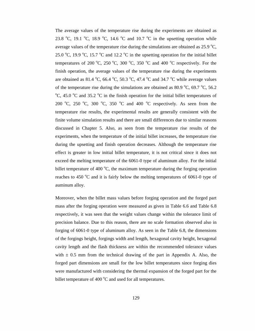
129
The average values of the temperature rise during the experiments are obtained as
23.8 oC, 19.1 oC, 18.9 oC, 14.6 oC and 10.7 oC in the upsetting operation while
average values of the temperature rise during the simulations are obtained as 25.9 oC,
25.0 oC, 19.9 oC, 15.7 oC and 12.2 oC in the upsetting operation for the initial billet
temperatures of 200 oC, 250 oC, 300 oC, 350 oC and 400 oC respectively. For the
finish operation, the average values of the temperature rise during the experiments
are obtained as 81.4 oC, 66.4 oC, 50.3 oC, 47.4 oC and 34.7 oC while average values
of the temperature rise during the simulations are obtained as 80.9 oC, 69.7 oC, 56.2 oC, 45.0 oC and 35.2 oC in the finish operation for the initial billet temperatures of
200 oC, 250 oC, 300 oC, 350 oC and 400 oC respectively. As seen from the
temperature rise results, the experimental results are generally consistent with the
finite volume simulation results and there are small differences due to similar reasons
discussed in Chapter 5. Also, as seen from the temperature rise results of the
experiments, when the temperature of the initial billet increases, the temperature rise
during the upsetting and finish operation decreases. Although the temperature rise
effect is greater in low initial billet temperature, it is not critical since it does not
exceed the melting temperature of the 6061-0 type of aluminum alloy. For the initial
billet temperature of 400 oC, the maximum temperature during the forging operation
reaches to 450 oC and it is fairly below the melting temperatures of 6061-0 type of
auminum alloy.
Moreover, when the billet mass values before forging operation and the forged part
mass after the forging operation were measured as given in Table 6.6 and Table 6.8
respectively, it was seen that the weight values change within the tolerance limit of
precision balance. Due to this reason, there are no scale formation observed also in
forging of 6061-0 type of aluminum alloy. As seen in the Table 6.8, the dimensions
of the forgings height, forgings width and length, hexagonal cavity height, hexagonal
cavity length and the flash thickness are within the recommended tolerance values
with ± 0.5 mm from the technical drawing of the part in Appendix A. Also, the
forged part dimensions are small for the low billet temperatures since forging dies
were manufactured with considering the thermal expansion of the forged part for the
billet temperature of 400 oC and used for all temperatures.

130
Table 6.6 Billet Dimensions and Billet Weights of the Aluminum Alloy 6061 for
Different Temperatures
Billet
Temp.
(oC)
Billet
No
Billet
Diameter
(mm)
Billet
Length
(mm)
Billet Mass
(g)
1 30.09 32.17 61.09
2 30.21 32.23 62.12
3 29.96 32.19 60.71
4 30.00 32.10 60.59
5 30.03 32.56 61.68
6 30.20 32.21 62.01
7 29.93 32.52 61.88
8 30.00 32.08 60.48
9 30.10 32.04 61.13
200
10 30.09 32.07 61.13
1 30.09 32.67 62.35
2 30.08 32.00 60.55
3 29.93 32.01 60.14
4 30.03 32.12 61.25
5 30.03 32.18 60.86
6 30.03 32.88 62.78
7 30.02 32.17 60.83
8 30.13 32.08 61.08
9 30.18 32.27 62.11
250
10 30.02 32.18 61.00
1 29.97 32.24 61.09
2 30.01 32.38 61.65
3 29.97 32.50 61.28
4 30.03 32.41 61.47
300
5 30.20 32.12 62.09
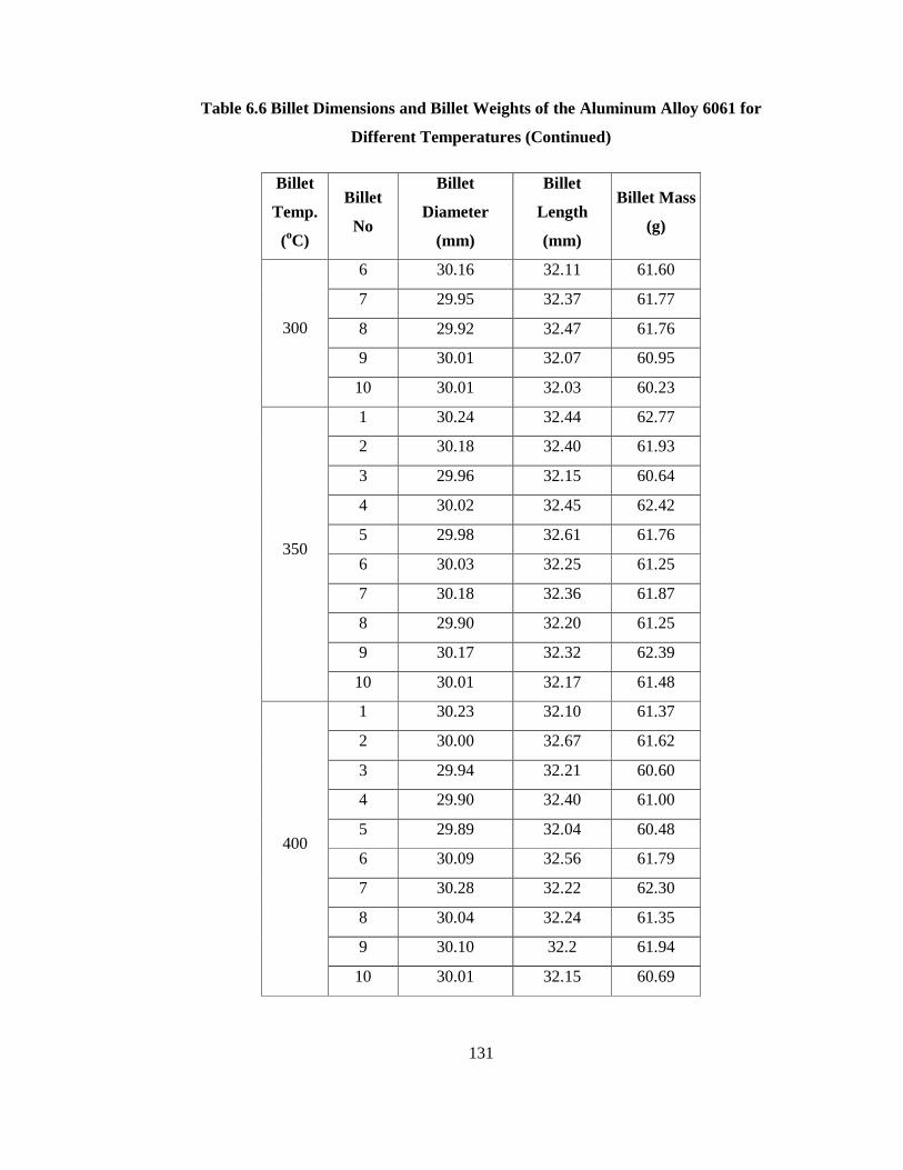
131
Table 6.6 Billet Dimensions and Billet Weights of the Aluminum Alloy 6061 for
Different Temperatures (Continued)
Billet
Temp.
(oC)
Billet
No
Billet
Diameter
(mm)
Billet
Length
(mm)
Billet Mass
(g)
6 30.16 32.11 61.60
7 29.95 32.37 61.77
8 29.92 32.47 61.76
9 30.01 32.07 60.95
300
10 30.01 32.03 60.23
1 30.24 32.44 62.77
2 30.18 32.40 61.93
3 29.96 32.15 60.64
4 30.02 32.45 62.42
5 29.98 32.61 61.76
6 30.03 32.25 61.25
7 30.18 32.36 61.87
8 29.90 32.20 61.25
9 30.17 32.32 62.39
350
10 30.01 32.17 61.48
1 30.23 32.10 61.37
2 30.00 32.67 61.62
3 29.94 32.21 60.60
4 29.90 32.40 61.00
5 29.89 32.04 60.48
6 30.09 32.56 61.79
7 30.28 32.22 62.30
8 30.04 32.24 61.35
9 30.10 32.2 61.94
400
10 30.01 32.15 60.69
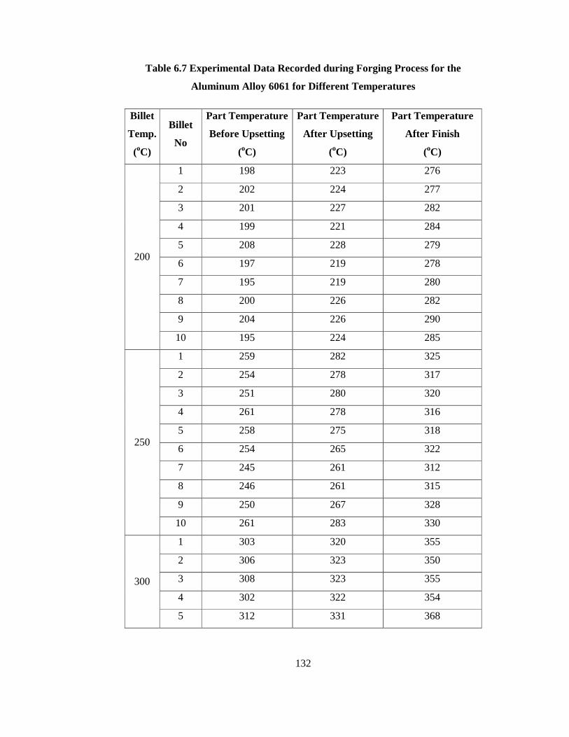
132
Table 6.7 Experimental Data Recorded during Forging Process for the
Aluminum Alloy 6061 for Different Temperatures
Billet
Temp.
(oC)
Billet
No
Part Temperature
Before Upsetting
(oC)
Part Temperature
After Upsetting
(oC)
Part Temperature
After Finish
(oC)
1 198 223 276
2 202 224 277
3 201 227 282
4 199 221 284
5 208 228 279
6 197 219 278
7 195 219 280
8 200 226 282
9 204 226 290
200
10 195 224 285
1 259 282 325
2 254 278 317
3 251 280 320
4 261 278 316
5 258 275 318
6 254 265 322
7 245 261 312
8 246 261 315
9 250 267 328
250
10 261 283 330
1 303 320 355
2 306 323 350
3 308 323 355
4 302 322 354
300
5 312 331 368
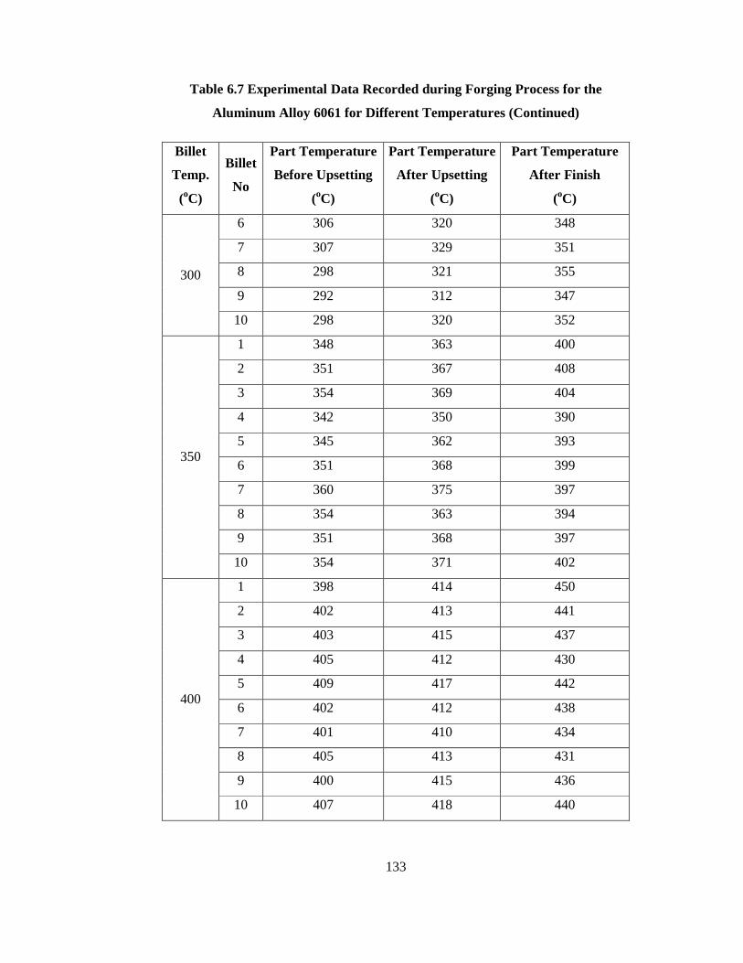
133
Table 6.7 Experimental Data Recorded during Forging Process for the
Aluminum Alloy 6061 for Different Temperatures (Continued)
Billet
Temp.
(oC)
Billet
No
Part Temperature
Before Upsetting
(oC)
Part Temperature
After Upsetting
(oC)
Part Temperature
After Finish
(oC)
6 306 320 348
7 307 329 351
8 298 321 355
9 292 312 347
300
10 298 320 352
1 348 363 400
2 351 367 408
3 354 369 404
4 342 350 390
5 345 362 393
6 351 368 399
7 360 375 397
8 354 363 394
9 351 368 397
350
10 354 371 402
1 398 414 450
2 402 413 441
3 403 415 437
4 405 412 430
5 409 417 442
6 402 412 438
7 401 410 434
8 405 413 431
9 400 415 436
400
10 407 418 440
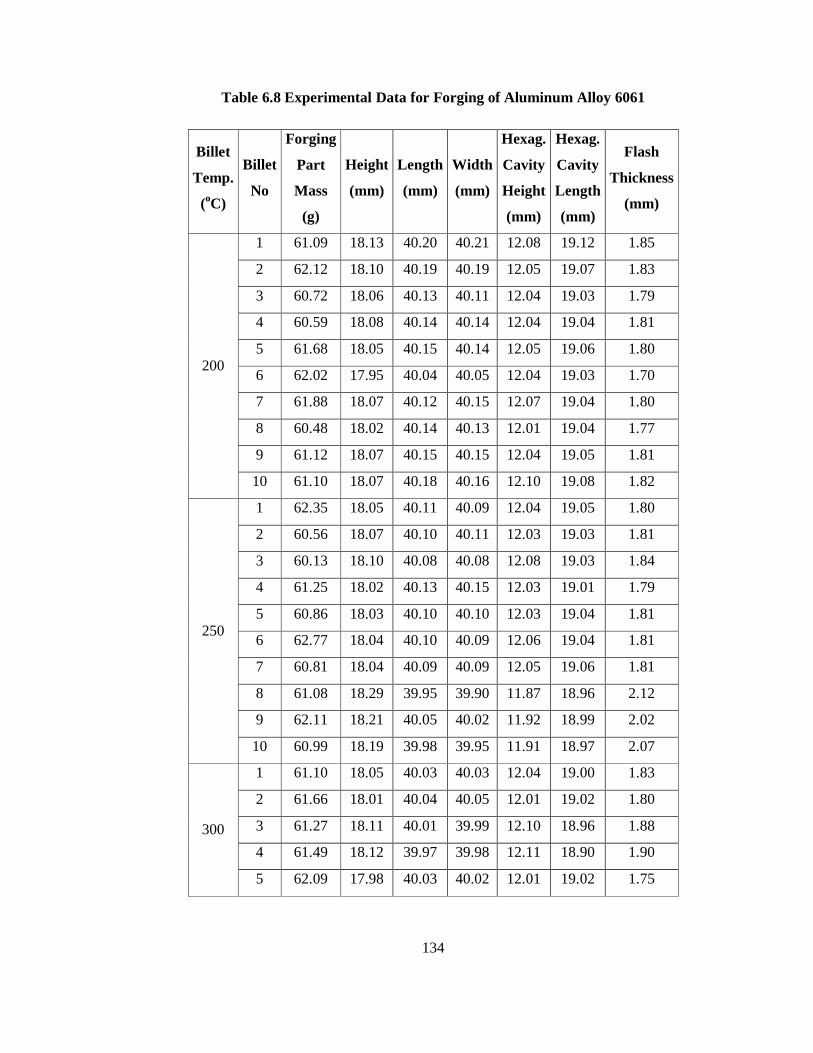
134
Table 6.8 Experimental Data for Forging of Aluminum Alloy 6061
Billet
Temp.
(oC)
Billet
No
Forging
Part
Mass
(g)
Height
(mm)
Length
(mm)
Width
(mm)
Hexag.
Cavity
Height
(mm)
Hexag.
Cavity
Length
(mm)
Flash
Thickness
(mm)
1 61.09 18.13 40.20 40.21 12.08 19.12 1.85
2 62.12 18.10 40.19 40.19 12.05 19.07 1.83
3 60.72 18.06 40.13 40.11 12.04 19.03 1.79
4 60.59 18.08 40.14 40.14 12.04 19.04 1.81
5 61.68 18.05 40.15 40.14 12.05 19.06 1.80
6 62.02 17.95 40.04 40.05 12.04 19.03 1.70
7 61.88 18.07 40.12 40.15 12.07 19.04 1.80
8 60.48 18.02 40.14 40.13 12.01 19.04 1.77
9 61.12 18.07 40.15 40.15 12.04 19.05 1.81
200
10 61.10 18.07 40.18 40.16 12.10 19.08 1.82
1 62.35 18.05 40.11 40.09 12.04 19.05 1.80
2 60.56 18.07 40.10 40.11 12.03 19.03 1.81
3 60.13 18.10 40.08 40.08 12.08 19.03 1.84
4 61.25 18.02 40.13 40.15 12.03 19.01 1.79
5 60.86 18.03 40.10 40.10 12.03 19.04 1.81
6 62.77 18.04 40.10 40.09 12.06 19.04 1.81
7 60.81 18.04 40.09 40.09 12.05 19.06 1.81
8 61.08 18.29 39.95 39.90 11.87 18.96 2.12
9 62.11 18.21 40.05 40.02 11.92 18.99 2.02
250
10 60.99 18.19 39.98 39.95 11.91 18.97 2.07
1 61.10 18.05 40.03 40.03 12.04 19.00 1.83
2 61.66 18.01 40.04 40.05 12.01 19.02 1.80
3 61.27 18.11 40.01 39.99 12.10 18.96 1.88
4 61.49 18.12 39.97 39.98 12.11 18.90 1.90
300
5 62.09 17.98 40.03 40.02 12.01 19.02 1.75
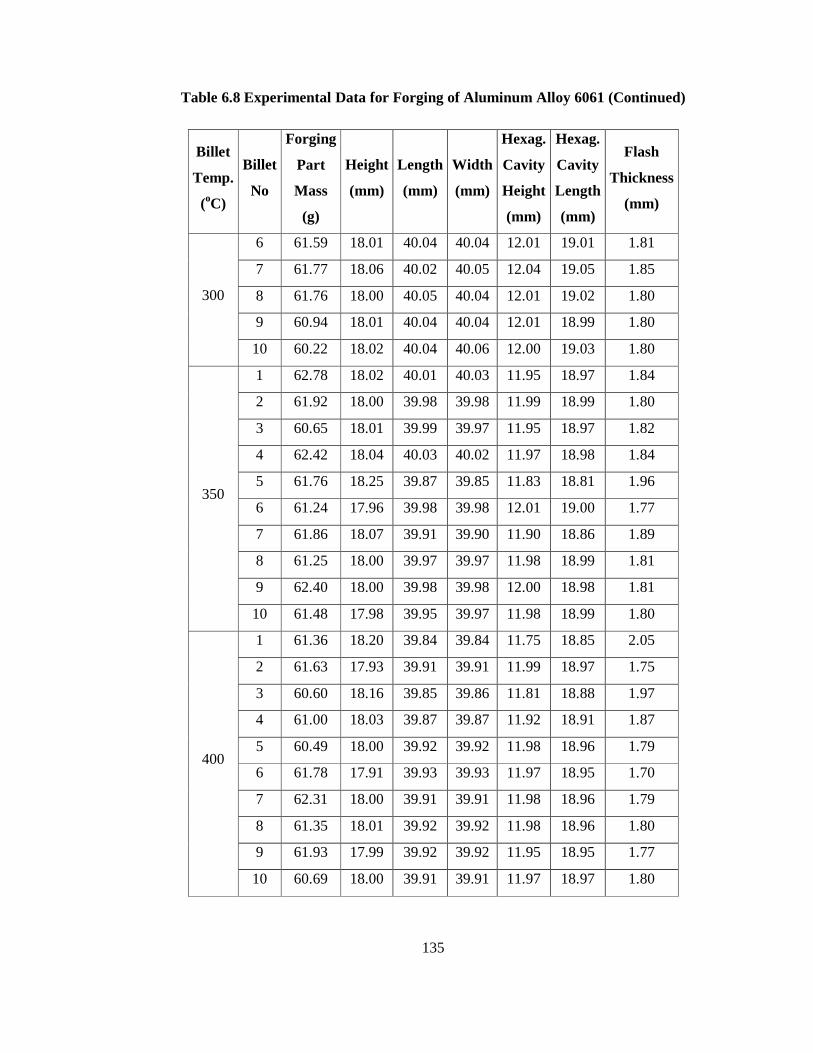
135
Table 6.8 Experimental Data for Forging of Aluminum Alloy 6061 (Continued)
Billet
Temp.
(oC)
Billet
No
Forging
Part
Mass
(g)
Height
(mm)
Length
(mm)
Width
(mm)
Hexag.
Cavity
Height
(mm)
Hexag.
Cavity
Length
(mm)
Flash
Thickness
(mm)
6 61.59 18.01 40.04 40.04 12.01 19.01 1.81
7 61.77 18.06 40.02 40.05 12.04 19.05 1.85
8 61.76 18.00 40.05 40.04 12.01 19.02 1.80
9 60.94 18.01 40.04 40.04 12.01 18.99 1.80
300
10 60.22 18.02 40.04 40.06 12.00 19.03 1.80
1 62.78 18.02 40.01 40.03 11.95 18.97 1.84
2 61.92 18.00 39.98 39.98 11.99 18.99 1.80
3 60.65 18.01 39.99 39.97 11.95 18.97 1.82
4 62.42 18.04 40.03 40.02 11.97 18.98 1.84
5 61.76 18.25 39.87 39.85 11.83 18.81 1.96
6 61.24 17.96 39.98 39.98 12.01 19.00 1.77
7 61.86 18.07 39.91 39.90 11.90 18.86 1.89
8 61.25 18.00 39.97 39.97 11.98 18.99 1.81
9 62.40 18.00 39.98 39.98 12.00 18.98 1.81
350
10 61.48 17.98 39.95 39.97 11.98 18.99 1.80
1 61.36 18.20 39.84 39.84 11.75 18.85 2.05
2 61.63 17.93 39.91 39.91 11.99 18.97 1.75
3 60.60 18.16 39.85 39.86 11.81 18.88 1.97
4 61.00 18.03 39.87 39.87 11.92 18.91 1.87
5 60.49 18.00 39.92 39.92 11.98 18.96 1.79
6 61.78 17.91 39.93 39.93 11.97 18.95 1.70
7 62.31 18.00 39.91 39.91 11.98 18.96 1.79
8 61.35 18.01 39.92 39.92 11.98 18.96 1.80
9 61.93 17.99 39.92 39.92 11.95 18.95 1.77
400
10 60.69 18.00 39.91 39.91 11.97 18.97 1.80
136
CHAPTER 7
CONCLUSIONS
7.1 Discussion of the Results
In this study, aluminum forging process of a particular part has been realized. The
forging part and dies are designed according to the aluminum forging design
parameters as explained in Chapter 3. The proposed forging process was simulated
for the initial billet temperatures of 375 oC, 400 oC and 425 oC for the 7075-0 type of
aluminum alloy; and for the initial temperatures of 200 oC, 250 oC, 300 oC, 350 oC
and 400 oC for the 6061-0 type aluminum alloy by a commercially available finite
volume program. Forging dies were produced in METU-BILTIR Center CAD/CAM
Laboratory and the experimental study was performed for the two different
aluminum alloy groups (Al 7075 and Al 6061) and five different forging
temperatures in METU-BILTIR Center Forging Research and Application
Laboratory. Results of the numerical and the experimental studies are compared and
conclusions are given as follows:
• To minimize the forging cost and forging time, firstly the process with single
stage operation has been considered by the finite volume simulation process.
However, it was seen that folds occur during single stage operation. In the
computer analysis, the forging process with two stages was found as
successful.
• The effective stress on the part decreases as the initial temperature of the
billet increases. The maximum effective stress occurs during the initial
contact of the lower and the upper die with the workpiece. The maximum
137
effective stress on the part during the open upsetting forging stage is lower
than that during the finish forging stage.
• The maximum effective stresses are relatively lower for the 6061-0 type of
aluminum alloy when compared to the 7075-0 type of aluminum alloy.
• The maximum die force increases as the initial temperature of the billet
decreases. The die forces slightly increase at the beginning of the finish
forging stage and then the die forces increases rapidly to fill the die cavity
completely. Moreover, the die forces are relatively lower for the forging of
6061-0 type of aluminum alloys when compared to the forging of 7075-0
type of aluminum alloys as seen from the finite volume simulation results.
• The part temperatures increase during the upsetting and finish forging
operations and the maximum temperatures occur at the zones where the
deformation on the part is high. Although the temperature rise seems to be
within the desired temperature range during aluminum forging simulations,
control of the temperature during experiments is critical to prevent the
melting of the aluminum billets during forging operations as discussed in
Chapter 4.
• The temperature rise is much higher in low forging temperatures which can
be attributed to close die and billet temperatures at the low forging
temperatures. As a result of this, there is less heat loss to the dies from the
part.
• The temperature rise is less in forging of 6061-0 type of aluminum alloy
when compared to the 7075-0 type of aluminum alloy as seen from the
simulation results of these two aluminum alloy groups.
• In the experiments, the forged parts were controlled by visual inspection to
find out if there is any unfilled region, surface crack or fold and it has been
observed that there are no such forging defects as seen in the finite volume
simulations. However, the cracks have been observed at the flash zone during

138
the forging of 7075-0 type of aluminum alloy for the forging temperatures of
200 oC, 250 oC, and 300 oC. Since, the flash is trimmed after the forging
operation, the crack formations at the flash are not critical. In addition, there
are no crack formations observed during the forging of 6061-0 type of
aluminum alloy for all forging temperatures. This shows that the forging of
the aluminum alloy 6061-0 is less severe compare to the forging of the
aluminum alloys 7075-0.
• During the experiments, it has been observed that heating of the aluminum
billets is not easy in the available induction heater due to low melting
temperature of the aluminum alloys. The electrical box type furnace available
in the METU-BILTIR Center was used however it is not suitable for mass
production.
• During the experiments, it has been observed that control of the aluminum
billet temperatures is very difficult since aluminum looses heat very rapidly
when it contacts with other metals. Also, aluminum looses heat quickly by
radiation while carrying of the aluminum billets from the furnace to the
forging press. Because of this reason, careful handling with the experienced
technician is required during the forging. Temperature of the forging dies
should be within the desired temperature range during the experiments to
achieve the similar results with the finite volume simulation results.
• The temperature values tabulated during the experiment are mostly consistent
with the finite volume simulation results. However, there are slight
discrepancy between the results due to the experimental setup such as heating
of the dies, heating of the billets and the sensitivity of the pyrometer used
during the forging operations.
• The billet masses before forging process and part masses after forging
process were weighed by using a precision balance for the two different
aluminum alloy groups (Al 7075 and Al 6061) and it has been seen that there
is no weight loss during the forging process. Therefore, it can be concluded
139
that there is no scale formation in aluminum forging. It has been also
observed during the visual inspection.
• The dimensions of the forging parts were measured by using the digital
calipers and it has been observed that the part dimensions are at the desired
tolerance which is ± 0.5 mm.
7.2 Future Works
Future works can be suggested as follows;
• Different types of aluminum alloys can be analyzed and experimentally tested
for different part geometries.
• The finite element analysis can be performed to see the effects of the
aluminum forging on the dies.
• Experimental study can be performed by obtaining force-stroke diagrams for
the forging press.
• Warm forging of the aluminum alloys can be studied in detail.
• Cold forging of the aluminum alloys can be studied.
• Precision forging of the aluminum alloys can be analyzed.
• Heating experiments can be performed with different heating equipment.
140
REFERENCES
[1] T. Altan, G. Ngaile, G.Shen, “Cold and Hot Forging: Fundamentals and
Applications”, ASM International, 2005.
[2] Keystone Forg. Co., web site: “http://www.keystoneforging.com/forgproc.htm”,
last accessed: 12 June 2008.
[3] J. S. Gunasekera, “CAD/CAM of Dies”, Ellis Horward Series in Mechanical
Engineering, Ohio University, Athens, USA 1989, Ellis Howard Limited.
[4] P.H. Kim, M.S. Chun, J.J. Yi, Y.H. Moon, “Pass Schedule Algorithms for Hot
Open Die Forging”, Journal of Materials Processing Technology, 130–131 (2002)
516–523.
[5] E. Korner, R. Knodler, “Possibility of Warm Extrusion in Combination with Cold
Extrusion”, Journal of Materials Processing Technology, 35 (1992) 451–465.
[6] Y.H. Kim, T.K. Ryou, H.J. Choi, B.B. Hwang, “An Analysis of the Forging
Processes for 6061 Aluminum-Alloy Wheels”, Journal of Materials Processing
Technology, 123 (2002) 270–276.
[7] S. A. Sheridan, “Forging Design Handbook”, American Society for Metals, 1972.
[8] A. M. Sabroff, F. W. Boulger, H. J. Henning, “Forging Materials and Practices”,
Batelle Memorial Institute Columbus, Ohio, 1968.
[9] S.E. Rusinoff, “Forging and Forming Metals”, American Technical Society,
Chicago, USA, 1952 first printing, 1959 reprinted.

141
[10] E. Paul DeGarmo, J. T. Black, Ronald A. Kohser, “Materials and Process in
Manufacturing”, Eighth Edition, John Wiley & Sons, Inc., 1999.
[11] George E. Totten, D. Scott MacKenzie, “Handbook of Aluminum: Physical
Metallurgy and Process”, Vol. 1, 2003.
[12] Victor Vazguez, Taylan Altan, “New Concepts in Die Design-Physical and
Computer Modelling Applications”, Journal of Materials Processing Technology, 98
(2000) 212-223.
[13] V. Bhavin Mehta, Ibrahim Al-Zkeri, Jay S. Gunasekera, “Evaluation of
MSC.SuperForge for 3D Simulation of Streamlined and Shear Extrusion Dies”,
MSC.Software Corporation, Ohio University, Athens, Ohio, USA, 2000.
[14] Harshil Parikh, Bhavin Mehta, Jay Gunasekera, “Forging Process Analysis and
Preform Design”, Department of Mechanical Engineering Ohio University, Athens,
Ohio 45701.
[15] Gökler, M., I., “Computer Aided Sequence and Die Design for Hot Upset
Forgings”, Ph.D. Thesis, University of Birmingham, England, 1983.
[16] Alper, E., “Computer Aided Design of Axi-Symmetric Press Forgings”, M. Sc.
Thesis, Middle East Technical University, Turkey, 1989.
[17] Elmaskaya, D., “Finite Element Analysis of Effects of Tapered Preforms in
Cold Upsetting”, M. Sc. Thesis, Middle East Technical University, Turkey, 1997.
[18] Kutlu, A, E., “Analysis and Design of Preforms for Non-Axisymmetric Press”,
M. Sc. Thesis, Middle East Technical University, Turkey, 2001.
[19] Đsbir, S. Ş., “Finite Element Analysis of Trimming”, M. Sc. Thesis, Middle East
Technical University, Turkey, 2002.
[20] Kazancı, B., “Design and Analysis of Hot Upset Forgings with Non-Circular
Cross-Sections”, M. Sc. Thesis, Middle East Technical University, Turkey, 2002.

142
[21] Civelekoğlu, B., “Analysis of Forging for Three Different Alloy Steels”, M. Sc.
Thesis, Middle East Technical University, Turkey, 2003.
[22] Karagözler, A., B., “Analysis and Preform Design for Long Press Forgings with
Non-Planar Parting Surfaces”, M. Sc. Thesis, Middle East Technical University,
Turkey, 2003.
[23] Abachi, S. “Wear Analysis of Hot Forging Dies”, M. Sc. Thesis, Middle East
Technical University, Turkey, 2004.
[24] Gülbahar, S., “Preform Design for Forging of Heavy Vehicle Steering Joint”, M.
Sc. Thesis, Middle East Technical University, Turkey, 2004.
[25] Aktakka, G., “Analysis of Warm Forging Process”, M. Sc. Thesis, Middle East
Technical University, Turkey, 2006.
[26] Masat, M., “Design and Implementation of Hot Precision Forging Die for a Spur
Gear”, M. Sc. Thesis, Middle East Technical University, Turkey, 2007.
[27] Saraç, S., “Design and Thermo-Mechanical Analysis of Warm Forging Process
and Dies”, M. Sc. Thesis, Middle East Technical University, Turkey, 2007.
[28] S. I. Wanga, M. K. Seoa, J. R. Chob, W. B. Baea, “A Study on the Development
of Large Aluminum Flange Using the Casting/Forging Process”, Journal of Materials
Processing Technology, 130–131 (2002) 294–298.
[29] O. Jensrud, K. Pedersen, “Cold Forging of High Strength Aluminum Alloys and
the Development of New Thermomechanical Processing”, Journal of Materials
Processing Technology, 80–81 (1998) 156–160.
[30] D. A. Tanner, J. S. Robinson, “Reducing Residual Stress in 2014 Aluminium
Alloy Die Forgings”, Journal of Material Design, 2007.
[31] H. Yoshimura, K. Tanaka, “Precision Forging of Aluminum and Steel”, Journal
of Materials Processing Technology, 98 (2000) 196-204.

143
[32] T. Altan, F. W. Boulger, J. R. Becker, N. Akgerman, H. J. Henning, “Forging
Equipment, Materials and Practices”, Air Force Materials Laboratory, October 1973.
[33] “Metals Handbook-Forming and Forging”, Vol. 14, 9th Edition, ASM
Handbook Committee. USA, 1988.
[34] “Metals Handbook-Forging and Casting”, Vol. 5, 8th Edition, ASM Handbook
Committee. USA, 1971.
[35] Nagaumi, H., Takeda, Y., Pongsukiwat, S., Umeda, T., “Hot Tear and its
Prevention of Irregular Near Net Shape D.C. Billet of High Strength Al-Mg-Si
Alloy” , Nippon Light Metal Company Ltd., Kambara, JAPAN.
[36] V. M. Kevorkijan, “Production Technology and Use of Aluminum Drop
Forging Components”, Slovenija, Journal of Materials Processing Technology, 35(3-
4) 191(2001).
[37] K. Siegert, D. Ringhand and R. Neher, “Designing of Forgings”, Institut für
Umformtechnik, Universität Stuttgart, 1994.
[38] H. So, Y. F. Lin, K. W. Huang, “Comparison of Flow Patterns Between
Plasticine and Aluminum Alloys in Hot-Precision Forging”, Journal of Materials
Processing Technology, 66 (1997) 39-48.
[39] H. J. Henning, “Aluminum Forging an Overview”, Forging, Jul-Aug2007, Vol.
18 Issue 4, p20-24.
[40] Alexandre Polozine, Lirio Schaeffer, “Exact and Approximate Methods for
Determining the Thermal Parameters of the Forging Process”, Journal of Materials
Processing Technology, 170 (2005) 611–615.
[41] D.B. Shan, Z. Wang, Y. Lu, K.M. Xue, “Study on Isothermal Precision Forging
Technology for Cylindrical Aluminum-Alloy Housing”, Journal of Materials
Processing Technology, 72 (1997) 403–406.
144
[42] J. R. Davis, “Heat Treating in Aluminum and Aluminum Alloys”, ASM
Specialty Handbook, p. 290, 1993.
[43] D. J. Mynors, A. N. Bramley and M. Allen, “An Examination of Manual Die
Design Procedures as a Precursor to the Application of Simulation”, UK,
International Conference and Exhibition on Design and Production of Dies and
Molds, Đstanbul, 1997.
[44] PRO/ENGINEER Wildfire 3.0.
[45] Simufact 3.0.
[46] Smeral QLZK UC Die Holder Manual.
[47] Private communication with ALMAR.
[48] Private communication with FNSS.
[49] Online Materials Information Resource, web site: “www.matweb.com”, last
accessed: 26 December 2008.
[50] A. Behrens, H. Schafstall, “2D and 3D Simulation of Complex Multistage
Forging Processes by Use of Adaptive Friction Coefficient”, Journal of Materials
Processing Technology, 80-81 (1998) 298-303.
[51] Private communication with Assab Korkmaz.
[52] Private communication with Inductotherm.
[53] Assab Korkmaz Dievar Tool Steel Catalog.

145
APPENDIX A
TECHNICAL DRAWING OF THE FORGING PART
Technical drawing of the forging part has been prepared by using PRO/ENGINEER
Wildfire 3.0 as given in Figure A.1. The first angle projection system is used for the
technical drawing since the first angle projection is the standard in Turkey and;
throughout the Asia and Europe.

146
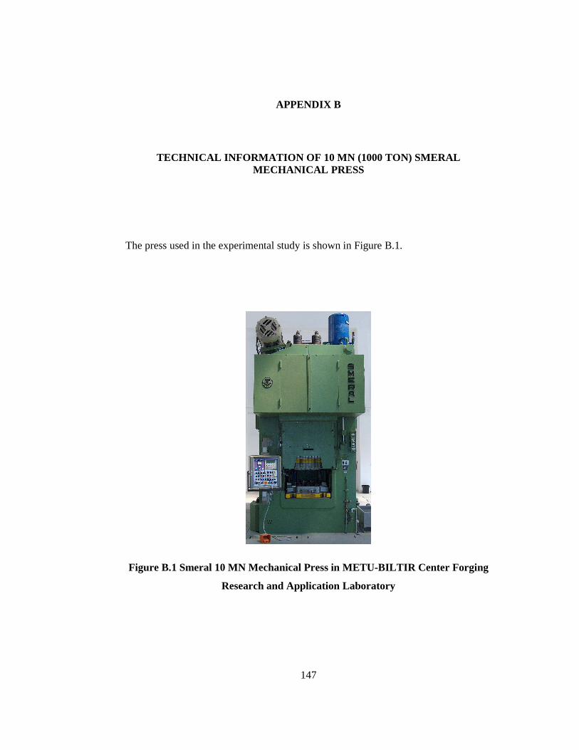
147
APPENDIX B
TECHNICAL INFORMATION OF 10 MN (1000 TON) SMERAL MECHANICAL PRESS
The press used in the experimental study is shown in Figure B.1.
Figure B.1 Smeral 10 MN Mechanical Press in METU-BILTIR Center Forging
Research and Application Laboratory

148
The technical information of the press is given as follows:
Nominal Forming Force : 10 MN
Ram Stroke : 220 mm
Shut Height : 620 mm
Ram Resetting : 10 mm
Rod Length : 750 mm
Crank Radius : 110 mm
Number of Strokes at Continuous Run : 100 min-1
Press Height : 4840 mm
Press Height above Floor : 4600 mm
Press Width : 2540 mm
Press Depth : 3240 mm
Press Weight : 48000 kg
Die Holder Weight : 3000 kg
Main Motor Input : 55 kW
Max. Stroke of the Upper Ejector : 40mm
Max. Stroke of the Lower Ejector : 50 mm
Max. Force of the Upper Ejector : 60 kN
Max. Force of the Lower Ejector : 150 kN

149
APPENDIX C
TECHNICAL DRAWING OF THE FORGING DIES
Technical drawing of the forging part is obtained by using PRO/ENGINEER
Wildfire 3.0 as given in Figure C.1 to Figure C.3.
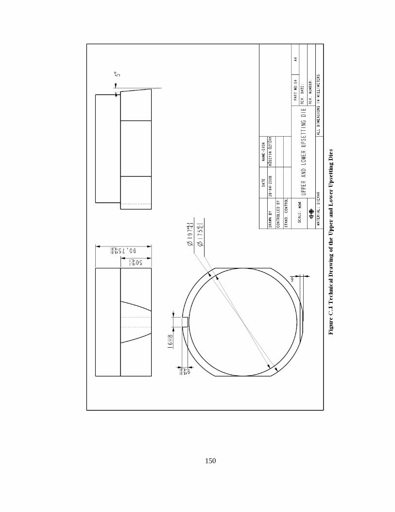
150
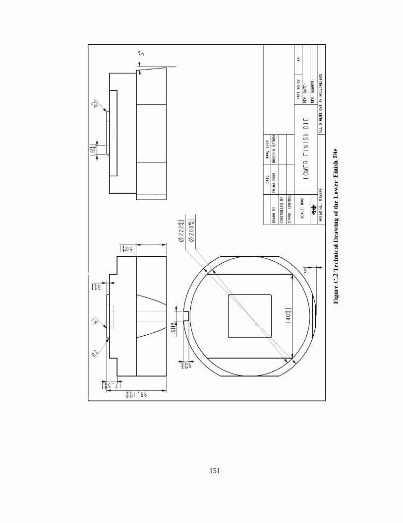
151

152
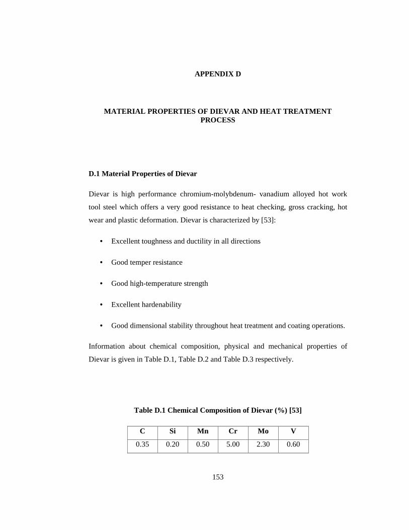
153
APPENDIX D
MATERIAL PROPERTIES OF DIEVAR AND HEAT TREATMENT PROCESS
D.1 Material Properties of Dievar
Dievar is high performance chromium-molybdenum- vanadium alloyed hot work
tool steel which offers a very good resistance to heat checking, gross cracking, hot
wear and plastic deformation. Dievar is characterized by [53]:
• Excellent toughness and ductility in all directions
• Good temper resistance
• Good high-temperature strength
• Excellent hardenability
• Good dimensional stability throughout heat treatment and coating operations.
Information about chemical composition, physical and mechanical properties of
Dievar is given in Table D.1, Table D.2 and Table D.3 respectively.
Table D.1 Chemical Composition of Dievar (%) [53]
C Si Mn Cr Mo V
0.35 0.20 0.50 5.00 2.30 0.60

154
Table D.2 Physical Properties of Dievar [53]
Temperature 20 oC 400 oC 600 oC
Density
(kg/m3) 7800 7700 7600
Modulus of Elasticity
(MPa) 210000 180000 145000
Coefficient of Thermal
Expansion per oC from 20 oC - 12.7 x 10⁻⁶ 13.3 x 10⁻⁶
Thermal Conductivity
(W/moC) - 31 32
Table D.3 Mechanical Properties of Dievar at Room Temperature for Different
Hardness Values [53]
Hardness
(HRC) 44 48 52
Ultimate Tensile
Strength
(MPa)
1480 1640 1900
Yield Strength
(MPa) 1210 1380 1560
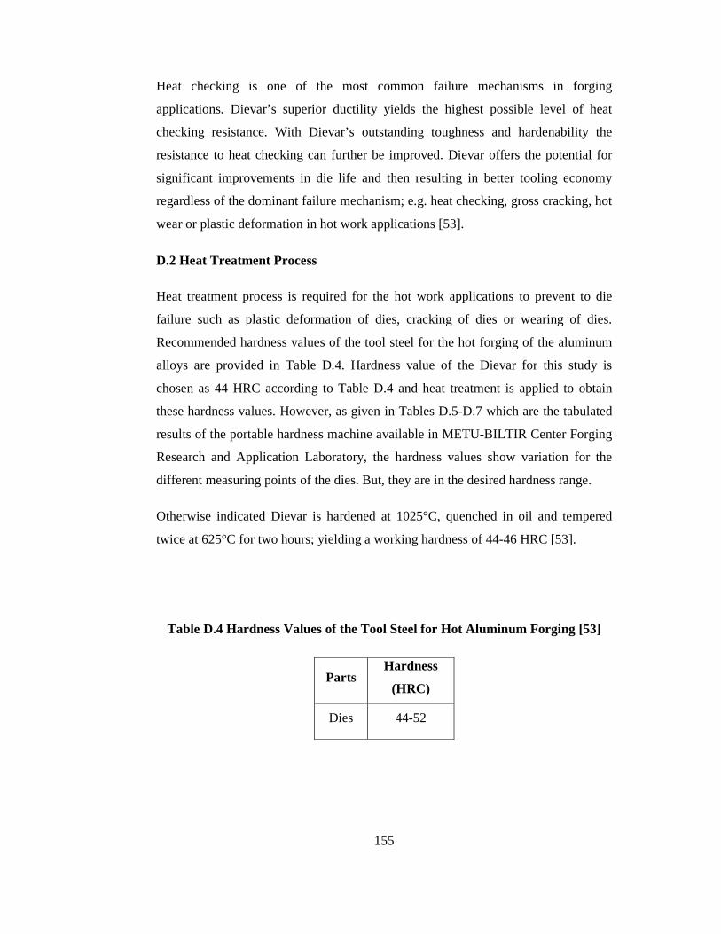
155
Heat checking is one of the most common failure mechanisms in forging
applications. Dievar’s superior ductility yields the highest possible level of heat
checking resistance. With Dievar’s outstanding toughness and hardenability the
resistance to heat checking can further be improved. Dievar offers the potential for
significant improvements in die life and then resulting in better tooling economy
regardless of the dominant failure mechanism; e.g. heat checking, gross cracking, hot
wear or plastic deformation in hot work applications [53].
D.2 Heat Treatment Process
Heat treatment process is required for the hot work applications to prevent to die
failure such as plastic deformation of dies, cracking of dies or wearing of dies.
Recommended hardness values of the tool steel for the hot forging of the aluminum
alloys are provided in Table D.4. Hardness value of the Dievar for this study is
chosen as 44 HRC according to Table D.4 and heat treatment is applied to obtain
these hardness values. However, as given in Tables D.5-D.7 which are the tabulated
results of the portable hardness machine available in METU-BILTIR Center Forging
Research and Application Laboratory, the hardness values show variation for the
different measuring points of the dies. But, they are in the desired hardness range.
Otherwise indicated Dievar is hardened at 1025°C, quenched in oil and tempered
twice at 625°C for two hours; yielding a working hardness of 44-46 HRC [53].
Table D.4 Hardness Values of the Tool Steel for Hot Aluminum Forging [53]
Parts Hardness
(HRC)
Dies 44-52

156
Table D.5 Hardness Values of the Upsetting Dies
Table D.6 Hardness Values of the Upper Finish Die

157
Table D.7 Hardness Values of the Lower Finish Die
The creep tests for the Dievar material of 44 HRC after the heat treatment process for
the different die temperature values are realized in METU Central Laboratory and
true stress-true strain curves obtained for the different temperatures are given in
Figures D.1-D.4.

158
True Stress vs True Strain
0
500000000
1000000000
1500000000
2000000000
2500000000
0 2 4 6 8 10 12 14 16
True Strain (mm/mm)
Tru
e S
tres
s (P
a)
Figure D.1 True Stress vs. True Strain Curve for 125 oC
True stress vs True Strain
0
500000000
1000000000
1500000000
2000000000
2500000000
0 2 4 6 8 10 12 14 16
True Strain (mm/mm)
Tru
e S
tres
s (P
a)
Figure D.2 True Stress vs. True Strain Curve for 200 oC
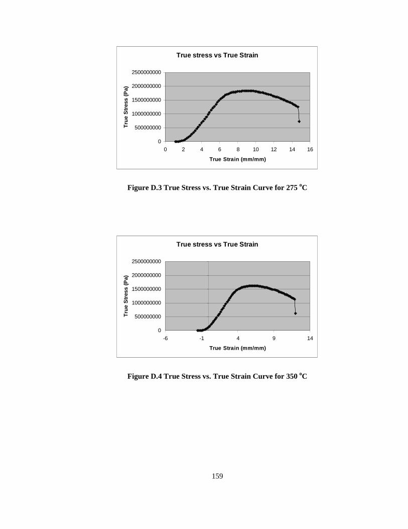
159
True stress vs True Strain
0
500000000
1000000000
1500000000
2000000000
2500000000
0 2 4 6 8 10 12 14 16
True Strain (mm/mm)
Tru
e S
tres
s (P
a)
Figure D.3 True Stress vs. True Strain Curve for 275 oC
True stress vs True Strain
0
500000000
1000000000
1500000000
2000000000
2500000000
-6 -1 4 9 14
True Strain (mm/mm)
Tru
e S
tres
s (P
a)
Figure D.4 True Stress vs. True Strain Curve for 350 oC

160
APPENDIX E
TECHNICAL INFORMATION OF THE COLORLESS WATER SOLUBL E LUBRICANT
Technical properties of the colorless water soluble lubricant are given as follows:
• Appearance: buff emulsion
• Density: 0.970 g/cc
• Solution Percentage: 5 %
• PH Value: 7-8
• Solvent: water (clean and not hard water)
• Application: spraying with air
The other properties can be given as:
• It is not flammable and used for hot working applications.
• It does not generate toxic gas during application.
• It is easy to clean from produced part.
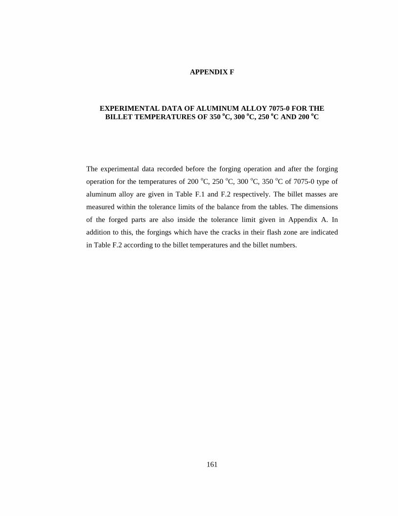
161
APPENDIX F
EXPERIMENTAL DATA OF ALUMINUM ALLOY 7075-0 FOR THE BILLET TEMPERATURES OF 350 oC, 300 oC, 250 oC AND 200 oC
The experimental data recorded before the forging operation and after the forging
operation for the temperatures of 200 oC, 250 oC, 300 oC, 350 oC of 7075-0 type of
aluminum alloy are given in Table F.1 and F.2 respectively. The billet masses are
measured within the tolerance limits of the balance from the tables. The dimensions
of the forged parts are also inside the tolerance limit given in Appendix A. In
addition to this, the forgings which have the cracks in their flash zone are indicated
in Table F.2 according to the billet temperatures and the billet numbers.

162
Table F.1 Billet Dimensions and Billet Weights of the Aluminum Alloy 7075 for
Different Temperatures
Billet
Temp.
(oC)
Billet
No
Billet
Diameter
(mm)
Billet
Length
(mm)
Billet
Mass
(g)
1 30.20 32.27 64.30
2 30.19 32.17 64.12
3 30.20 32.07 64.05
4 30.13 32.35 64.03
5 30.27 32.37 64.84
6 30.22 32.22 64.23
7 30.21 32.28 64.27
8 30.20 31.92 63.85
9 30.17 32.23 63.91
200
10 30.21 32.09 63.92
1 30.15 32.18 63.96
2 30.14 32.11 63.83
3 30.19 31.95 63.59
4 30.25 32.14 64.42
5 30.22 32.00 63.98
6 30.16 32.29 64.24
7 30.17 31.86 63.37
8 30.14 32.28 64.09
9 30.24 31.98 63.76
250
10 30.20 31.94 63.57
1 30.15 31.98 63.74
2 30.06 32.12 63.61
3 30.21 31.90 63.96
4 30.24 32.16 64.10
300
5 30.14 32.04 63.96
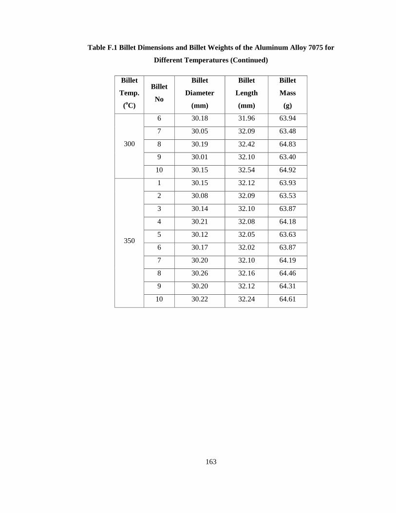
163
Table F.1 Billet Dimensions and Billet Weights of the Aluminum Alloy 7075 for
Different Temperatures (Continued)
Billet
Temp.
(oC)
Billet
No
Billet
Diameter
(mm)
Billet
Length
(mm)
Billet
Mass
(g)
6 30.18 31.96 63.94
7 30.05 32.09 63.48
8 30.19 32.42 64.83
9 30.01 32.10 63.40
300
10 30.15 32.54 64.92
1 30.15 32.12 63.93
2 30.08 32.09 63.53
3 30.14 32.10 63.87
4 30.21 32.08 64.18
5 30.12 32.05 63.63
6 30.17 32.02 63.87
7 30.20 32.10 64.19
8 30.26 32.16 64.46
9 30.20 32.12 64.31
350
10 30.22 32.24 64.61

164

165
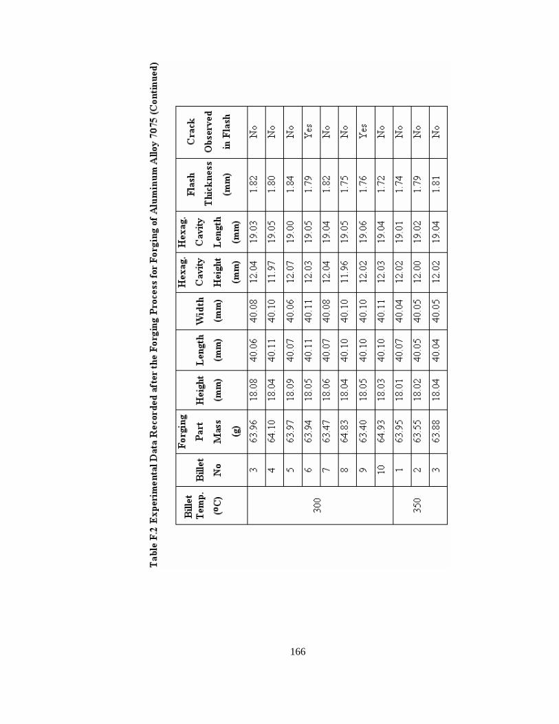
166

167