analysis and design of coleman transform-based individual...
TRANSCRIPT

This is a repository copy of Analysis and design of Coleman transform-based individual pitch controllers for wind-turbine load reduction.
White Rose Research Online URL for this paper:http://eprints.whiterose.ac.uk/90499/
Version: Accepted Version
Article:
Lu, Q., Bowyer, R. and Jones, B.L. (2015) Analysis and design of Coleman transform-based individual pitch controllers for wind-turbine load reduction. Wind Energy, 18 (8). 1451 - 1468. ISSN 1095-4244
https://doi.org/10.1002/we.1769
[email protected]://eprints.whiterose.ac.uk/
Reuse
Unless indicated otherwise, fulltext items are protected by copyright with all rights reserved. The copyright exception in section 29 of the Copyright, Designs and Patents Act 1988 allows the making of a single copy solely for the purpose of non-commercial research or private study within the limits of fair dealing. The publisher or other rights-holder may allow further reproduction and re-use of this version - refer to the White Rose Research Online record for this item. Where records identify the publisher as the copyright holder, users can verify any specific terms of use on the publisher’s website.
Takedown
If you consider content in White Rose Research Online to be in breach of UK law, please notify us by emailing [email protected] including the URL of the record and the reason for the withdrawal request.

WIND ENERGY
Wind Energ. 2013; 00:1–18
DOI: 10.1002/we
RESEARCH ARTICLE
Analysis and design of Coleman Transform-based individualpitch controllers for wind turbine load reduction.
Q. Lu1, R. Bowyer2, B. Ll. Jones3
1Department of Mechanical Engineering Science, University of Surrey, Guildford, GU2 7XH, UK.2McLaren Applied Technologies Limited, McLaren Technology Centre, Chertsey Road, Woking, Surrey, GU21 4YH, UK.3Department of Automatic Control and Systems Engineering, The University of Sheffield, Sheffield, S1 3JD, UK.
ABSTRACT
As the size of wind turbines increases the effects of dynamic loading on the turbine structures becomes increasingly
significant. There is therefore a growing demand for turbine control systems to alleviate these unsteady structural loads
in addition to maintaining basic requirements such as power and speed regulation. This has motivated the development
of blade Individual Pitch Control (IPC) methodologies, many of which employ the Coleman Transformation to simplify
the controller design process. However, and as is shown in this paper, the Coleman Transformation significantly alters the
rotational system dynamics when these are referred to the non-rotating frame of reference, introducing tilt-yaw coupling
in the process. Unless this transformation is explicitly included in the model employed for IPC design then the resulting
controllers can yield poor performance. Therefore, in this paper we show how to model the Coleman Transformation in a
form that is amenable to IPC analysis and synthesis. This enables us to explain why traditional design parameters of gain
and phase margin are poor indicators of robust stability, and hence motivate the need for a multivariable design approach.
The robust multivariable IPC approach advocated in this paper is based upon H∞ loop-shaping and has numerous desirable
properties, including reliable stability margins, improved tilt-yaw decoupling and simultaneous rejection of disturbance
loads over a range of frequencies. The design of a robust multivariable IPC is discussed and simulation results are presented
that demonstrate the efficacy of this controller, in terms of load reduction on both rotating and non-rotating turbine parts.
Copyright c© 2013 John Wiley & Sons, Ltd.
KEYWORDS
Individual pitch control; load reduction; Coleman Transformation; H∞ loop-shaping
Correspondence
Q. Lu, Department of Mechanical Engineering Science, University of Surrey, Guildford, GU2 7XH, UK.
E-mail: [email protected]
Received . . .
1. INTRODUCTION
Within the wind energy industry, it is well known that the rotors of wind turbine generators (WTGs) are subjected to
significant unbalanced and fluctuating loads caused by gravitational force, wind shear, yaw error, tower shadow, and
atmospheric turbulence [1]. These forces give rise to unsteady mechanical loads on the blade roots, which are subsequently
transferred to the hub and other non-rotating turbine structures (e.g. main bearing, yaw bearing, nacelle and tower),
resulting in unsteady tilt and yaw loads on the turbine main structure. Such loads can lead to fatigue damage and reduced
turbine lifetime if not taken care of in the design of an appropriate WTG control system. Despite this, and as noted by [2],
the majority of control approaches are based upon assumptions of uniform and constant wind across the rotor plane. Such
an approach is that of collective pitch control (CPC), which although a widely adopted method for achieving turbine speed
regulation [2, 3], is unable to attenuate non-uniform and unsteady loads. Consequently, this has motivated the study of
control techniques based upon individual pitch control (IPC). In this paper, we focus on investigating this pitch control
technique and its application on three-bladed horizontal axis wind turbines.
The majority of existing IPC studies employ a coordinate transformation technique commonly known as the Coleman
Transformation. This transformation originated from the field of helicopter rotor control [4] and similar techniques such
Copyright c© 2013 John Wiley & Sons, Ltd. 1
Prepared using weauth.cls [Version: 2010/06/17 v1.00]

Individual Blade-Pitch Control Q. Lu
as the d-q transformation are also employed in the field of electrical machines and power electronics [5]. Early adoption
of the Coleman Transformation for addressing IPC problems was reported in [6] and [7]. Its main principle is to project
the rotating blade loads onto a set of non-rotating coordinates that yield orthogonal tilt and yaw loads. The blade loads
can then be reduced by designing separate controllers to attenuate the tilt and yaw loads, although this requires some
care as the mapping of load frequencies between rotating and fixed turbine structures is non-trivial. As noted in [1], the
unsteady loads encountered by WTGs are concentrated at certain harmonics. The blade loads present harmonics at 1p (once
per revolution), 2p, 3p, etc., frequencies, while for three-bladed turbines, the loads on the non-rotating turbine structure
only contain harmonics at 3p, 6p, etc., frequencies [6]. The remaining harmonics on the non-rotating turbine structure are
moved to their adjacent harmonics at frequency multiples of 3p [8]. For example, 1p harmonics on the rotating coordinate
are transferred to 0p (static content) on the non-rotating coordinate, while 2p and 4p harmonics are transferred to the 3p
harmonic. Owing to such relationships existing between the loads on the blades and the non-rotating turbine structure, it
is feasible to develop one controller to reduce these loads simultaneously and across a range of frequencies.
From a controls design perspective, the Coleman Transformation is attractive since it transforms a time-periodic and
hence time-varying system into one that is time-invariant. Furthermore, if the dynamics of the system are linear, or can be
approximated as such, then the resulting WTG model is linear and time-invariant (LTI), for which a substantial body of
mature and sophisticated control systems theory can immediately be brought to bear upon the design of IPCs [9]. In terms
of the control system architecture, the Coleman Transformation also offers the important benefit of enabling the IPC to be
largely decoupled from an existing CPC [9, 10].
The conventional form of Coleman Transformation-based IPC approaches was reported in [6] and [7]. This focused
on reducing the static content of the tilt and yaw loads, with corresponding reduction of the 1p blade loads. However,
this approach ignored all other higher frequency disturbance loads, including the 3p content of the tilt and yaw loads
that have been found to be the main cause of fatigue-induced damage on the non-rotating turbine structures [11, 12]. As
a direct consequence of this, modifications to the conventional IPC approach were proposed in [12] and [13] in order
to address the control of these higher frequency loads. These modifications were implemented by using a ‘modified
Coleman Transformation’ concept, whereby the process of demodulation and remodulation was defined for higher blade
load frequencies (2p, 3p, etc.) such that these higher frequencies were modulated to 0p, and then attenuated using the
conventional 1p load reduction approach. Control of these blade load frequencies (i.e. 1p, 2p, 3p etc) was typically achieved
through the use of two, separate, proportional-integral (PI) controllers to attenuate the 0p content in the modulated loads.
However, using such single-input-single-output (SISO) controllers implicitly assumes that the tilt and yaw dynamics are
decoupled after application of the Coleman Transform, which was shown not to be the case in [9] and [10], where dynamic
tilt-yaw coupling was shown to exist, with the degree of coupling heavily influenced by the rotor speed. This subsequently
motivated the study of multivariable control approaches.
The majority of multivariable IPC studies have focused upon the use of optimal control techniques. Examples include
the application of linear quadratic regulators (LQR) [14] and linear quadratic gaussian (LQG) control [9]. Robust control
has received less attention, with a signal-based H∞ method considered in [10]. Recognition on the existence of coupling
between the tilt and yaw loops has been reported in these papers, with some discussion of the improvement over existing
SISO approaches.
Design requirements for IPCs are typically specified in the frequency domain, in terms of load reductions at specific
frequencies. Directly targeting such frequencies is difficult to achieve via LQR/LQG control, where performance objectives
are typically specified in the time domain. Also, it is well known that LQG controllers possess no guaranteed stability
margins [15], thus making it difficult to assess the robustness of such controllers to the typical sources of uncertainty
inherent in any control problem. Such uncertainties arise from imprecise model parameters, uncertain high-frequency
dynamics and lack of knowledge concerning the magnitude and frequencies of external disturbances entering the system.
This motivates the use of robust control in this paper.
Of the various multivariable robust control design methodologies, H∞ loop-shaping [16, 17] would appear well-suited
to designing IPCs. As the name suggests, control design in this approach is conducted in the frequency domain by
directly adjusting the system’s frequency response (i.e. loop-shaping) in a similar fashion as is conducted in classical
control techniques, such as PI and lead-lag compensation. In principle, therefore, a single controller can be designed to
simultaneously attenuate multiple blade and fixed turbine structure loads across a range of frequencies. In addition, H∞
loop-shaping employs a generic uncertainty model that accounts for parametric and dynamic uncertainty, with controllers
synthesised to maximise the degree of uncertainty that the closed-loop system can tolerate, thereby yielding robustness.
The use of a generic uncertainty model greatly simplifies the controller design process, particularly compared to LQG
design where the statistics of the disturbances, together with the manner in which they influence the system states must a
priori be provided by the designer. Furthermore, the degree of robustness is succinctly captured by a robust stability margin,
and it is shown in this paper that such a stability margin provides a reliable indicator of IPC stability and performance. This
stability margin can also be computed for other controllers, hence allowing meaningful comparisons to be drawn between
different controllers at the design stage.
2 Wind Energ. 2013; 00:1–18 c© 2013 John Wiley & Sons, Ltd.
DOI: 10.1002/we
Prepared using weauth.cls
Q. Lu Individual Blade-Pitch Control
As mentioned above, the design of H∞ loop-shaping controllers requires the provision of a system’s frequency response.
In the context of the present IPC problem, the system model should not only include relevant WTG dynamics, but also the
frequency response of the Coleman Transform and its inverse. In this paper we derive these frequency responses and use
them to show how the dynamics of the Coleman Transform can, if not accounted for in the controller design, give rise to
undesirable closed-loop behaviour. A practically motivated example, based on the use of band-pass filters to remove the
DC content of blade-load strain-gauge sensors, is presented to highlight these effects.
Although this paper is primarily focused upon the design of Coleman Transformation-based IPC approaches, it is
worth mentioning at this point that other IPC approaches have been investigated that have not employed this transform.
The majority of these studies directly employed a periodic time-varying wind turbine model. For example, a lifted
repetitive IPC was developed in [18], a periodic disturbance accommodating controller was proposed in [19] and a
periodic LQR controller was developed and applied to floating offshore wind turbines in [20] and [21]. As an alternative to
the Coleman Transform, IPC based on the Clark Transform was studied in [8], where it was shown that such a transform
eliminates the need to obtain a measurement of the rotor azimuth angle. Studies such as [22] and [23] designed IPCs based
on LTI turbine models that did not employ a coordinate transform. In [22], the dynamics associated with changes in rotor
azimuthal position were not included in a two-bladed WTG model that subsequently formed the basis for a LQG-based
IPC design. In [23], a LTI model was obtained by averaging the underlying time-varying dynamics over the rotor rotational
period. However, as pointed out by [23], such methods eliminated periodic terms in the system dynamics, and thus should
be treated with care.
The IPC approaches referenced above are based on turbine models that typically describe the dynamics of the rotating
(blades) and fixed (tower, main bearing, etc.) WTG components. The single, centralised controllers that arise from these
models thus aim to simultaneously reduce the loads on each blade, as well as the loads on the other turbine components. It
is worth mentioning, that an alternative IPC approach, termed ‘single blade control’, was proposed in [24]. In this approach,
each blade was equipped with its own controller that operated independently from the other blades in response to its local
load measurements. Only the blade model was required to design the controller and the Coleman Transformation was
not used in this approach. According to [24], the main benefits of this approach included ease of controller design and
implementation. Another single blade control approach was reported in [25], in which blade flow measurements (inflow
angle and relative velocity) were used instead of load measurements.
The remainder of this paper is organised as follows. In Section 2 we discuss the modelling aspects of the IPC problem
and derive the frequency response of the Coleman Transformation and its inverse, and combine this with a simplified
WTG model to obtain an IPC model that forms the basis for subsequent analysis and controller design. The influence
of the Coleman Transformation on the system dynamics is also explained in this section. This is followed in Section 3
by a discussion of the limitations of a benchmark IPC design, where the dynamics of the Coleman Transformations are
neglected, before presenting the proposed robust IPC approach and its benefits over the benchmark design. In Section 4, a
robust IPC is designed and results are presented from closed-loop simulation upon a high fidelity aeroelastic model of an
exemplar multi-MW offshore turbine∗. Finally, Section 5 presents the conclusions of this paper.
2. MODEL FOR IPC ANALYSIS AND DESIGN
A conceptual control systems architecture of a Coleman Transformation-based IPC is depicted in Figure 1. Typically, IPC
and CPC are implemented separately, with the design of the former based on one of the control methodologies described
in Section 1 (PID, LQG, etc.). With respect to the model-based control design methodologies, standard turbine models
typically include the dynamics of the fixed and rotating turbine components, and are thus time-varying in nature owing
to the changing angular orientation of the rotating blades [9]. Application of the Coleman Transformation to the inputs
and the inverse Coleman Transformation to the outputs of the rotational system, relating blade pitch angles to blade root
bending moments, gives rise to a transformed system defined in a fixed coordinate frame. Such a system is time-invariant
and hence more amenable to standard feedback control design techniques.
With reference to Figure 1, the collective pitch controller computes the averaged blade-pitch angle demand θ(t) for
regulating the rotor speed ω0(t). This is passed through the Coleman Transform, along with the tilt and yaw referred pitch
angles, θtilt(t) and θyaw(t), respectively, to yield the total pitch angle demands on each blade, θ1,2,3(t), according to the
∗For reasons of commercial sensitivity, it is not possible for the authors to publish precise values for some of the parameters of the models employed in this work. In
such instances, and wherever appropriate, normalised values will be presented where absolute values are precluded.
Wind Energ. 2013; 00:1–18 c© 2013 John Wiley & Sons, Ltd. 3DOI: 10.1002/we
Prepared using weauth.cls

Individual Blade-Pitch Control Q. Lu
Figure 1. Systems architecture of a Coleman Transformation-based IPC. Additional inputs to the turbine, such as wind loading and
generator torque, are accounted for in the term f(t). The system within the shaded region represents the Coleman Transformed
turbine, whose dynamics are linear and time invariant once the turbine model is linearised around a fixed operating point.
following expression:
θ1(t)θ2(t)θ3(t)
:=
1 cosφ(t) sinφ(t)
1 cos
(
φ(t) +2π
3
)
sin
(
φ(t) +2π
3
)
1 cos
(
φ(t) +4π
3
)
sin
(
φ(t) +4π
3
)
θ(t)θtilt(t)θyaw(t)
, (1a)
where φ(t) is the rotor azimuth angle. The relevant outputs of the turbine are the total blade root flap-wise bending
moments, M1,2,3(t), that are related to the tilt and yaw moments, Mtilt(t) and Myaw(t) via the inverse Coleman
Transform:
M(t)Mtilt(t)Myaw(t)
:=
1
3
1
3
1
32
3cosφ(t)
2
3cos
(
φ(t) +2π
3
)2
3cos
(
φ(t) +4π
3
)
2
3sinφ(t)
2
3sin
(
φ(t) +2π
3
)2
3sin
(
φ(t) +4π
3
)
M1(t)M2(t)M3(t)
. (1b)
The averaged flap-wise blade bending moment is M(t) and has a physical interpretation in terms of the hub loading, but
is not commonly considered in IPC schemes. In order to isolate the action of the individual pitch controller from that of
the collective pitch controller, it is convenient to redefine the total pitch demands and blade moments as follows:
θ1(t)θ2(t)θ3(t)
:=
θ(t) + θ1(t)
θ(t) + θ2(t)
θ(t) + θ3(t)
,
M1(t)M2(t)M3(t)
:=
M(t) + M1(t)
M(t) + M2(t)
M(t) + M3(t)
, (2)
where θ1,2,3(t) are perturbations in blade pitch angle demand, arising from a linear combination of the tilt and yaw
angles θtilt(t), θyaw(t), as is evident from (1a). Similarly, M1,2,3(t) represent perturbations in the flap-wise blade bending
moment signals. Subsequent linearisation of the turbine dynamics around a steady turbine rotor speed yields a model that
describes the behaviour of M1,2,3(t) in response to changes in the inputs θ1,2,3(t), as shown in Figure 2. It is evident from
this figure that the model employed for IPC design should include not only the turbine dynamics, but also the dynamics
of the Coleman Transform and its inverse. Such models can be obtained from the numerical methods employed by such
software tools such as NREL’s MBC3 [23] and ECN’s TURBU codes [26]. However, the models obtained from these
codes can be large (e.g. around 600 states for a typical TURBU model [9]) and are presented in numerical state-space
form, which to some extent obscures the structure of the Coleman Transformed model. In contrast, the use of a low-order
4 Wind Energ. 2013; 00:1–18 c© 2013 John Wiley & Sons, Ltd.
DOI: 10.1002/we
Prepared using weauth.cls

Q. Lu Individual Blade-Pitch Control
Figure 2. System model for analysis and design of IPC after linearisation of the turbine model in Figure 1. Here, the linearised system
models the dynamics relating perturbations in the pitch demands to the resulting perturbations in the flap-wise root bending moments
of each blade, via the blade model G (3a). After application of the Coleman Transformation and its inverse (4), the inputs to the
transformed system are the tilt and yaw oriented pitch angles, whilst the outputs are the tilt and yaw bending moments. The dynamics
of the system enclosed within the shaded region are derived in Section 2.2, and play a central role in designing the controller K in
section 4.2
.
model in this work aids system analysis, in terms of understanding the effect of the Coleman Transforms upon the system
dynamics, and also simplifies subsequent controller design. As will be shown later in Section 4, the controllers synthesised
from such a low-order model yield acceptable performance when tested upon a higher fidelity turbine model. The following
subsections describe the construction of the model employed in this work for IPC analysis and design.
2.1. Low-order wind-turbine model
Referring to Figure 2, the wind turbine model employed in the present work consists of three identical transfer
functions G(s), where s is a complex variable, that relate the perturbation blade pitch-angle demands θ1,2,3 to respective
perturbation blade root flap-wise bending moments M1,2,3, and are modelled as follows:
G(s) := Ga(s)Gb(s)Gbp(s), (3a)
where Ga(s), Gb(s) and Gbp(s) are, respectively, the transfer functions that describe the pitch actuator, blade, and sensor
band-pass filter dynamics. These are defined as follows:
Ga(s) :=1
1 + τs, (3b)
Gb(s) :=dMflap
dθ
(2πfb)2
s2 +Db2πfbs+ (2πfb)2, (3c)
Gbp(s) :=2πfhs
s2 + 2π(fh + fl)s+ 4π2fhfl. (3d)
A description of the parameters of these transfer functions are listed in Table I. In the present study, the values for the
actuator and blade systems are obtained from the turbine simulation model (described in Section 4) linearised about its
steady state, rated speed of approximately 10 rpm. The band-pass filter (3d) is included in the system model to remove
low-frequency drift and high frequency noise from the bending moment measurements obtained from typical strain-gauge
sensors. The pitch actuator (3b) and blade dynamics (3c) are approximated as first and second-order systems, respectively,
whilst the band-pass filter is also second-order. The resulting model G(s) is therefore fifth-order. Clearly, this neglects the
higher-frequency blade modes as well as the dynamics of the non-rotating turbine structure. However, as will be shown
in the following sections, the robust controllers synthesised from this low-order model can be made insensitive to these
neglected dynamics, justifying the use of (3) as a model for feedback controller design. For the particular model parameters
employed in this study, the resulting transfer function is:
G(s) =1.2× 10⁵s
0.1s5 + 2.2s4 + 17.3s3 + 62.0s2 + 88.7s+ 7.3. (3e)
We next turn our attention to the dynamics of the Coleman Transformations on either side of the turbine model.
Wind Energ. 2013; 00:1–18 c© 2013 John Wiley & Sons, Ltd. 5DOI: 10.1002/we
Prepared using weauth.cls

Individual Blade-Pitch Control Q. Lu
Parameter Units Description
τ sec Pitch actuator time constantdMflap
dθkNm/deg Variation of blade flap-wise bending moment with respect to pitch angle
fb Hz Natural frequency of first blade flap-wise mode
Db Blade aerodynamic damping ratio
fh Hz Bandpass filter high corner frequency
fl Hz Bandpass filter low corner frequency
Table I. Model parameters of G(s) (3).
2.2. Frequency domain representation of the Coleman Transformation
With respect to the Coleman relationships (1), linearisation removes explicit dependence of the turbine model upon the
averaged quantities θ(t) and M(t), and so attention need only be paid to the tilt and yaw signals in the fixed reference
frame. The Coleman relationships of relevance to the IPC problem are therefore a subset of (1) and are defined as follows:
θ1(t)
θ2(t)
θ3(t)
:=
cosφ(t) sinφ(t)
cos
(
φ(t) +2π
3
)
sin
(
φ(t) +2π
3
)
cos
(
φ(t) +4π
3
)
sin
(
φ(t) +4π
3
)
︸ ︷︷ ︸
T (φ(t))
[θtilt(t)θyaw(t)
]
, (4a)
with the inverse transformation:
[Mtilt(t)Myaw(t)
]
:=2
3
cosφ(t) cos
(
φ(t) +2π
3
)
cos
(
φ(t) +4π
3
)
sinφ(t) sin
(
φ(t) +2π
3
)
sin
(
φ(t) +4π
3
)
︸ ︷︷ ︸
Tinv(φ(t))
M1(t)
M2(t)
M3(t)
. (4b)
Similar transforms were employed in [6], however, a subtle but crucially important to point to emphasise is that the
transforms T (φ(t)) and Tinv(φ(t)) are time-dependent, and should therefore be treated as dynamic operators. With this
in mind, we now derive one of the main results of this paper, namely the frequency response of the Coleman Transformed
model.
Noting that T (φ(t)) and Tinv(φ(t)) consist of trigonometric identities, and that φ(t) = ω0t, the following Laplace
Transforms are of use:
L [u(t) cosφ(t)] = L [u(t) cos(ω0t)] = L[
u(t)ejω0t + e−jω0t
2
]
=1
2(U(s− jω0) + U(s+ jω0)) , (5a)
L [u(t) sinφ(t)] = L [u(t) sin(ω0t)] = L[
u(t)j(e−jω0t − ejω0t
)
2
]
=j
2(U(s+ jω0)− U(s− jω0)) , (5b)
where u(t) is an arbitrary input signal, U(s) is its Laplace Transform, and j :=√−1. Substituting these into (4) yields
the frequency responses of the Coleman Transformation and its inverse as follows.
θ1(s)
θ2(s)
θ3(s)
= CT−
[θtilt(s− jω0)θyaw(s− jω0)
]
+ CT+
[θtilt(s+ jω0)θyaw(s+ jω0)
]
, (6a)
[Mtilt(s)Myaw(s)
]
=2
3C−
M1(s− jω0)
M2(s− jω0)
M3(s− jω0)
+2
3C+
M1(s+ jω0)
M2(s+ jω0)
M3(s+ jω0)
, (6b)
where C− and C+ are defined as:
C− :=1
2
[1 j
−j 1
] [cos(0) cos
(2π3
)cos
(4π3
)
sin(0) sin(2π3
)sin
(4π3
)
]
, C+ :=1
2
[1 −j
j 1
] [cos(0) cos
(2π3
)cos
(4π3
)
sin(0) sin(2π3
)sin
(4π3
)
]
. (6c)
6 Wind Energ. 2013; 00:1–18 c© 2013 John Wiley & Sons, Ltd.
DOI: 10.1002/we
Prepared using weauth.cls

Q. Lu Individual Blade-Pitch Control
Using the blade model (3), the frequency response between pitch angle perturbations and blade root flap-wise bending
moments perturbations is given by:
M1(s)
M2(s)
M3(s)
=
G(s) 0 00 G(s) 00 0 G(s)
θ1(s)
θ2(s)
θ3(s)
(7)
Substituting (6) into (7) yields the following Coleman transformed model for IPC analysis and design:
[Mtilt(s)Myaw(s)
]
=
G(s+ jω0) +G(s− jω0)
2jG(s+ jω0)−G(s− jω0)
2
−jG(s+ jω0)−G(s− jω0)
2
G(s+ jω0) +G(s− jω0)
2
︸ ︷︷ ︸
P (s, ω0)
[θtilt(s)θyaw(s)
]
(8)
Several remarks are in order here. Firstly, equations (6a) and (6b) describe the frequency domain relationship between
blade moments and pitch angles in fixed and rotating coordinates. These equations clearly capture the frequency shifts
that occur in transforming from fixed to rotating coordinates upon application of the Coleman Transform. For example,
referring to (6b), bending moment signals of frequency ω in the fixed coordinates arise as the sum of the bending moments
at shifted frequencies ω ± ω0 in rotating coordinates. This explains why, as was mentioned in Section 1, the major tilt
and yaw loads at 0p arise from the 1p blade loads, and similarly, how 3p tilt and yaw loads originate from 2p and 4p
blade loads. Secondly, P (s, ω0) in (8) is the transfer function matrix relating pitch angles to bending moments in fixed
coordinates. Provided the rotor speed ω0 remains constant, then P (s, ω0) is time-invariant and is thus a suitable model
for LTI controller design. It is immediately apparent that the off-diagonal elements of P (s, ω0) do not necessarily equate
to zero, in which case dynamic coupling exists between the tilt and yaw loops, further implying that traditional IPC
approaches based on SISO control methods may be problematic. The following two sections employ (8) as the basis for
system analysis and controller design.
3. ANALYSIS
Designing an IPC based on the dynamics of the turbine alone (3), without accounting for the dynamics of the Coleman
Transformation, can lead to poor closed-loop performance, possibly leading to loss of stability, as will now be shown.
3.1. A motivating example
It is apparent from (4) that the Coleman Transforms are time varying matrices, owing to the time dependence of the rotor
azimuth angle. Unless this time dependence is accounted for, then these matrices become static and so would not introduce
the frequency splitting clearly apparent in (6). In such a case, the transfer function matrix relating θtilt,yaw to Mtilt,yaw
assumes the form of (9a), which has the same dynamics as the original system G(s), with no coupling between the tilt and
yaw loops.
Pbm(s) :=
[G(s) 00 G(s)
]
. (9a)
For such a decoupled MIMO system, it is reasonable to employ a SISO control approach in what will henceforth be
termed a ‘benchmark’ IPC design, where the controller K is implemented as two identical and decoupled feedback
controllers, Kbm separately controlling the tilt and yaw responses.
K(s) :=
[Kbm(s) 0
0 Kbm(s)
]
. (9b)
The tilt and yaw controllers Kbm typically take the form of a PI compensator in series with a notch filter that removes
signal content at the 3p frequency. Such a controller regulates the static content of the tilt and yaw moments and can be
realised as follows:
Kbm(s) :=
(
Kp
1 + Tis
Tis
)
︸ ︷︷ ︸
PI controller
(s2 + 2D1(2πf3p)s+ 4π2f2
3p
s2 + 2D2(2πf3p)s+ 4π2f23p
)
︸ ︷︷ ︸
3p notch filter
(D1 < D2). (9c)
The parameters of this controller are described in Table II and the parameters of the PI controller can be designed to yield
satisfactory gain and phase margins of the open-loop compensated system G(s)Kbm(s), using classical design techniques
Wind Energ. 2013; 00:1–18 c© 2013 John Wiley & Sons, Ltd. 7DOI: 10.1002/we
Prepared using weauth.cls

Individual Blade-Pitch Control Q. Lu
Parameter Units Description
Kp kNm/deg Proportional gain
Ti sec Integral time
D1 First notch filter damping ratio
D2 Second notch filter damping ratio
f3p Hz 3p frequency
Table II. Controller parameters of Kbm(s) (9c).
based on bode-plot analysis, for example. Using such an approach, the following controller transfer function was obtained,
that yielded gain and phase margins of 3.7 and 57◦, respectively:
Kbm =3× 10⁻⁴s3 + 6× 10⁻⁴s2 + 3.3× 10⁻³s+ 6.5× 10⁻³
s3 + 6.6s2 + 10.8s. (9d)
According to classical control theory, such margins would lead one to expect good robustness and performance from
the closed-loop tilt and yaw responses. However, simulating this controller in a closed-loop fashion upon the wind turbine
simulation model of Section 5 reveals this is not the case, as shown by the square-dashed plot in Figures 10 and 11, where an
unexpected large peak appears at the 1p frequency in the tilt and yaw bending moments. The reason for this is, as explained
in more detail in the following section, is that the benchmark control model (9a) neglects the Coleman Transformation-
induced frequency shifting and dynamic coupling that are clearly evident in (8). Therefore it can be concluded that the
SISO stability criteria of gain and phase margin are unreliable indicators of stability and performance for the present
control problem. This does not necessarily mean that desirable performance can not be achieved using SISO controllers,
since an exhaustive search over the space of such controllers might prove otherwise. However, the lack of a reliable stability
margin to guide the search would necessitate extensive and time-consuming closed-loop simulations, with no guarantee of
a successful outcome, and would not provide any insight as to why the SISO stability margins were unreliable indicators
of stability and performance.
3.2. Influence of the Coleman Transformation on system dynamics
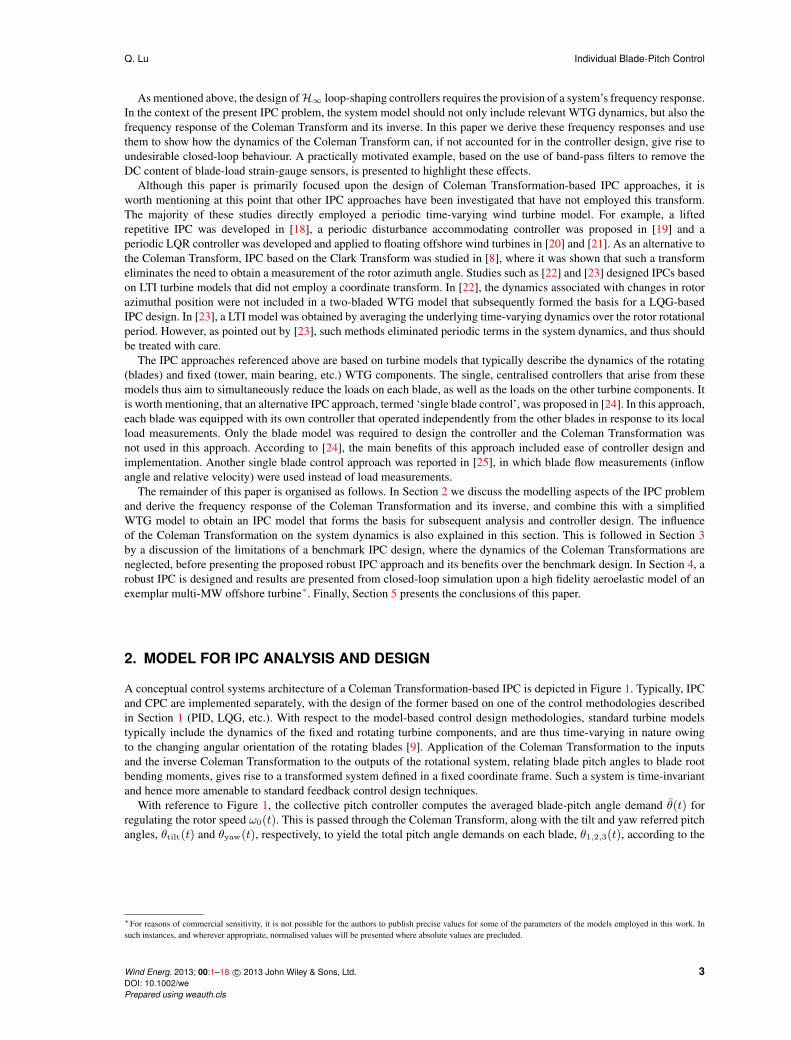
The poor stability prediction of gain and phase margin demonstrated above can be explained by considering the influence
of the Coleman Transformation on the system dynamics. Figure 3 shows the poles and zeros of the system models with
and without inclusion of the dynamics of the Coleman Transformation, P (ω0, s) (8) and Pbm(s) (9a) respectively. This
shows that the Coleman Transformation splits the poles and zeros of Pbm(s) into a pair of complex-conjugate poles and
zeros. In particular, note how the zero of the bandpass filter (3d) is split into a pair of purely imaginary zeros with a natural
frequency of ω0 (1p frequency). From a control design perspective, this is problematic since increasing the gain of any
feedback controller will result in the migration of system poles towards these zeros, resulting in a closed-loop system with
poles on the imaginary axis. The resulting closed-loop system will therefore display an undamped response in the tilt and
yaw loads at the 1p frequency.
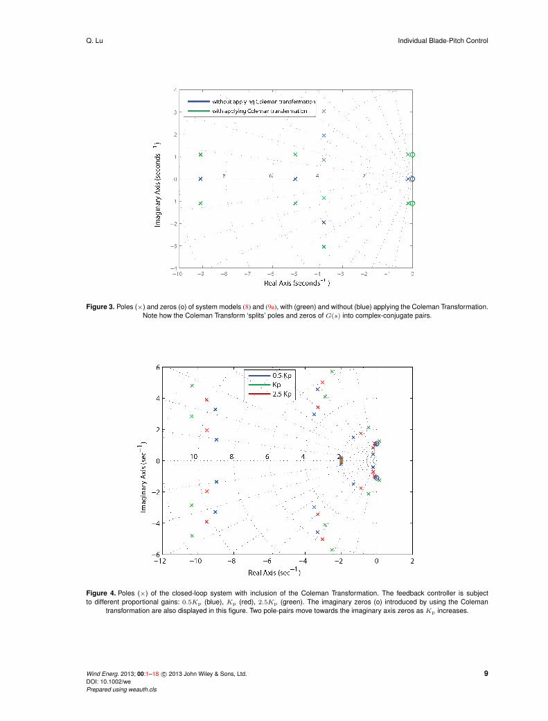
To demonstrate this effect, consider the closed-loop system consisting of the Coleman Transformed model (8) connected
in feedback with the benchmark controller defined in (9b). The poles of this closed-loop system are shown in Figure 4 for
three values of the proportional gain Kp. As this gain is increased, two pole-pairs of the closed-loop system migrate
towards the imaginary axis zeros at the 1p frequency. For the nominal value of Kp employed in (9d), one of these two
pole-pairs is a negligible distance from the imaginary axis hence explaining the poorly damped resonant behaviour at the
1p frequency. As the gain is increased further to a value of 2.5Kp, one pole-pair moves across into the complex right-
half plane, resulting in closed-loop instability. For comparison, the poles of the closed-loop system without inclusion of
the Coleman Transformation are provided in Figure 5 for the same values of Kp. Not only does Figure 5 fail to show a
resonant pole at 1p frequency for the nominal value of Kp, but it also fails to show the loss of closed-loop stability at the
higher gain of 2.5Kp.
3.3. Influence of the Coleman Transformation on tilt-yaw coupling
Inspection of the the Coleman Transformed turbine model P (s, ω0) (8) reveals that its off-diagonal elements may be
nonzero, in contrast to the model assumed in the benchmark approach Pbm(s) (9a). The magnitude and phase relationships
of the off-diagonal element G(s+ jω0)−G(s− jω0), as a function of frequency, are shown in the Bode plots of
Figure 6. This figure clearly shows that the signal gain of the off-diagonal elements is significantly greater than unity
up to a frequency of 16Hz, hence implying that significant coupling exists between the tilt and yaw loops. Such coupling
suggests that classical SISO control design methods are therefore not best suited to controlling the system as modelled
by P (s, ω0).
8 Wind Energ. 2013; 00:1–18 c© 2013 John Wiley & Sons, Ltd.
DOI: 10.1002/we
Prepared using weauth.cls
Q. Lu Individual Blade-Pitch Control
Figure 3. Poles (×) and zeros (o) of system models (8) and (9a), with (green) and without (blue) applying the Coleman Transformation.
Note how the Coleman Transform ‘splits’ poles and zeros of G(s) into complex-conjugate pairs.
Figure 4. Poles (×) of the closed-loop system with inclusion of the Coleman Transformation. The feedback controller is subject
to different proportional gains: 0.5Kp (blue), Kp (red), 2.5Kp (green). The imaginary zeros (o) introduced by using the Coleman
transformation are also displayed in this figure. Two pole-pairs move towards the imaginary axis zeros as Kp increases.
Wind Energ. 2013; 00:1–18 c© 2013 John Wiley & Sons, Ltd. 9DOI: 10.1002/we
Prepared using weauth.cls

Individual Blade-Pitch Control Q. Lu
Figure 5. Poles (×) of the closed-loop system without inclusion of the Coleman Transformation. The feedback controller have the same
values of Kp as in Figure 4. The pole-pairs still move towards the imaginary axis as Kp increases, but do so in a less aggressive
fashion in the absence of the imaginary zeros in Figure 4. Therefore, the poorly damped 1p oscillation for the nominal value of Kp is
not predicted, and neither is closed-loop instability for a higher proportional gain of 2.5Kp.
Figure 6. Bode diagram of the off-diagonal element G(s + jω0) − G(s − jω0) in the Coleman Transformed turbine model P (s, ω0).
The signal gain is greater than unity up to a frequency of 16Hz, implying significant cross-excitation between the tilt and yaw dynamics
up to this frequency.
4. CONTROLLER DESIGN
The preceding analysis has shown that IPC design based upon the benchmark model Pbm(s), as defined in (9a), is flawed,
since it neglects the pole-zero splitting and tilt-yaw coupling introduced by the Coleman Transformation. This section
therefore describes the design of an IPC that is based upon the transformed model P (s, ω0) (8).10 Wind Energ. 2013; 00:1–18 c© 2013 John Wiley & Sons, Ltd.
DOI: 10.1002/we
Prepared using weauth.cls

Q. Lu Individual Blade-Pitch Control
4.1. H∞ loop-shaping
For the purposes of ease of comparison and application, it is desirable that an alternative IPC system possess the same
structure as depicted in Figure 1. The presence of significant dynamic coupling between the tilt and yaw loops suggests
the use of a multivariable controller. As mentioned in the introduction, a wide variety of multivariable control design
techniques exist, and so it is prudent to select one that is appropriate to the particular problem in hand. Given that the basic
turbine model (3a), from which (8) is constructed, neglects many of the dynamics of an actual turbine, it is reasonable to
adopt a robust control technique, capable of yielding controllers that are insensitive to unmodelled dynamics. Furthermore,
for the purposes of load reduction it is desirable to specify performance requirements in the frequency domain. The
requirement for a robust, multivariable control approach in which design criteria are specified in the frequency domain
naturally suggests the use of H∞ loop-shaping [16, 17] in order to design the IPC. Such loop-shaping controllers have
found use in a variety of applications, ranging from the flight control of vertical take-off aircraft [27], active damping of
flexible space structures [16], control of combustion oscillations [28] and bluff body form-drag reduction [29]. Background
material concerning this control design approach is presented in Appendix A. The design of H∞ loop-shaping controllers
is essentially a two-stage process that is summarised as follows:
(i) Design a pre-compensator W (s) to shape the singular values of the shaped system Ps(s, ω0) := P (s, ω0)W (s) in
a desirable fashion, similar to that performed in classical lead-lag compensation. This typically takes the form of
ensuring the shaped system has high loop gain at low frequencies (for good low-frequency disturbance rejection)
and low gain at high frequencies (for good sensor noise rejection). The formulae in Appendix A can then be used to
compute and check that the maximum attainable robust stability margin of the shaped plant, εmax(Ps), is sufficiently
high. For further details of the robust stability margin, the reader is referred to [16, 17], but we remark briefly that
this scalar quantity is a generalisation to multivariable systems of classical SISO system gain and phase margins.
As a brief illustrative example, for a SISO feedback system with εmax(Ps) = 0.3, the corresponding gain and
phase margins are at least 2 and 35◦, respectively [30]. Owing to the generic uncertainty model (coprime factor
uncertainty) employed in this control framework, it can be shown [31] that higher values of the robust stability
margin give rise to closed-loop systems that are more robust to inaccurate model parameters, unmodelled high
frequency dynamics, and a range of other generic disturbances that are commonly encountered in feedback systems.
(ii) Synthesise the central loop-shaping controller K∞(s, ω0) that achieves the maximum robust stability margin of the
previous step, noting that automated routines in software packages such as MATLAB make this a straightforward
process. The central controller is then combined in series with the precompensator of the previous step to yield the
actual IPC for implementation K(s, ω0) := W (s)K∞(s, ω0).
We next demonstrate the application of H∞ loop-shaping control to the design of a robust multivariable IPC.
4.2. Robust Multivariable IPC Design
The following numerical example assumes that the transformed turbine model P (s, ω0) is parameterised by the transfer
function in (3e) and is operating with a steady rotor speed of approximately 10 rpm (ω0 ≈ 1 rad/s). The IPC objective of
the present study is to attenuate tilt and yaw load disturbances at the 0p and 3p frequencies, 0 Hz and 0.5 Hz, respectively.
The controller design begins by inspecting the frequency response of the turbine model P (s, ω0), whose singular
values as a function of frequency are shown in Figure 7. In order to achieve the specified load reductions, extra loop-
gain is required at frequencies up to an including 3p, and in order to prevent excessive pitch actuator usage, the unity-gain
crossover frequency should not be greatly in excess of the 3p frequency. In an attempt to achieve these objectives, the
following diagonal precompensator W (s) was designed:
W (s) :=
[W1(s) 0
0 W1(s)
]
, where W1(s) :=
(
Kp
1 + Tis
Tis
)
︸ ︷︷ ︸
PI controller
(s2 + 2D1(2πf3p)s+ 4π2f2
3p
s2 + 2D2(2πf3p)s+ 4π2f23p
)
︸ ︷︷ ︸
3p inverse notch filter
(D1 > D2), (10)
with the parameters of W1(s) described in Table III. The chosen transfer function of W1(s) was as follows:
W1(s) =4.5× 10⁻⁴s3 + 3.9× 10⁻³s2 + 10.8× 10⁻³s+ 9.8× 10⁻³
s3 + 0.66s2 + 10.8s. (11)
This precompensator was then combined in series with the turbine model to form the shaped model P (s, ω0)W (s), from
which the loop-shaping controller K(s, ω0) was synthesised. The achieved loop-shape PK(s, ω0) is displayed in Figure 7
and shows the desired features of high gains at low frequencies, a gain greater than unity at the 3p frequency, followed by
low gain at higher frequencies. The robust stability margin of the shaped model was computed as εmax = 0.48, suggesting
a robust design. Based on the shaped model, the central loop shaping controller was synthesised and combined with
Wind Energ. 2013; 00:1–18 c© 2013 John Wiley & Sons, Ltd. 11DOI: 10.1002/we
Prepared using weauth.cls

Individual Blade-Pitch Control Q. Lu
Figure 7. Singular value plots of the wind turbine model P (s, ω0)(dash-dot line), the shaped model P (s, ω0)W (s)(solid line) and the
achieved loop-shape PK(s, ω0)(dash line), where K(s, ω0) is the H∞ loop-shaping controller synthesised from the shaped model.
Parameter Units Description
Kp kNm/deg Proportional gain
Ti sec Integral time
D1 First inverse notch filter damping ratio
D2 Second inverse notch filter damping ratio
f3p Hz 3p frequency
Table III. Precompensator parameters of W1(s) (10).
the precompensator to form the final controller K(s, ω0). The loop-shape achieved by the system PK(s, ω0) is displayed
in Figure 7 and shows little degradation compared to the specified loop-shape of P (s, ω0)W (s). This concludes the design
of the robust multivariable IPC controller, ready for closed-loop implementation in the next section. We emphasis that this
design process requires very little tuning of the controller parameters in order to achieve the shaped loop in Figure 7,
thereby attenuating loads at 0p and 3p frequencies. The magnitude bode diagrams of the individual transfer functions
that make up K(s, ω0) are plotted in Figure 8. The off-diagonal elements K12(s, ω0) and K21K(s, ω0) show similar
gains to the on-diagonal elements, indicating the ‘true’ multivariable nature of this controller. To further demonstrate the
effectiveness of robust multivariable IPC K(s, ω0) on decoupling the interactions between the tilt and yaw control loops,
magnitude bode diagrams of the sensitivity closed-loop transfer functions (I + PK(s, ω0))−1 are shown in Figure 9. The
off-diagonal diagrams indicate coupling between the tilt and yaw loops, and it is clear from these that the H∞ multivariable
controller attenuates such cross excitation, given that the disturbance gain is less than unity across all frequencies. The same
is not true of the benchmark SISO controller, where cross-excitation is significantly amplified at frequencies around 0.2 Hz.
5. RESULTS: CLOSED-LOOP IPC SIMULATIONS
For the purpose of comparison, the robust multivariable IPC, designed in the previous section, and a benchmark IPC was
tested upon a high fidelity wind turbine simulation model. This simulation model represents the dynamics of a multi MW
commercial offshore wind turbine generator. The simulation model is an aero-elastic model based on Flex5 code [32]
and includes the tower dynamics, shaft dynamics and high frequency vibrational blade modes. It is therefore of much
12 Wind Energ. 2013; 00:1–18 c© 2013 John Wiley & Sons, Ltd.
DOI: 10.1002/we
Prepared using weauth.cls

Q. Lu Individual Blade-Pitch Control
Figure 8. Magnitude bode plots of K(s, ω0). The off-diagonal elements K12(s, ω0) and K21(s, ω0) are of similar magnitude to the
on-diagonal elements K11(s, ω0) and K22(s, ω0).
Figure 9. Magnitude bode plots of the closed-loop sensitivity function (I + PK(s, ω0))−1 with respect to different controllers. The
off-diagonal plots show the H∞ multivariable controller attenuates across all frequencies the effect of disturbances in the tilt loop
upon the output of the yaw loop, and vice-versa.
greater complexity than the basic model (3a) used for controller design in the present study. The simulation environment
allows mean wind speed, wind shear, and wind turbulence to be defined before each simulation run. The simulations
were run for sufficient duration to obtain convergence of the load spectra. The turbulence model used in this simulation
was approximated by a second-order low pass filter driven by Gaussian white noise. For the present study, the turbine
was regulated at its rated speed of approximately 10 rpm by its existing baseline control system (featuring a generator
controller and a collective pitch controller). The performance of the applied IPC was assessed in terms of loads reduction
on blade roots and main bearing, as these are usually subject to the largest unsteady loads. The pitch actuator activity was
also assessed. The benchmark controller was designed according to the model (3a), with exception of the proportional
gain, which was set to a more conservative values of 0.5Kp in order to prevent the 1p oscillations.
Wind Energ. 2013; 00:1–18 c© 2013 John Wiley & Sons, Ltd. 13DOI: 10.1002/we
Prepared using weauth.cls

Individual Blade-Pitch Control Q. Lu
Controllers Robust stability margin
Benchmark SISO IPC ε(P,Kbm) = 0.25
SISO robust IPC ε(P,KH∞) = 0.29
Multivariable robust IPC εmax(P ) = 0.48
Table IV. Stability margin with respect to different IPCs
The spectrum of the tilt and yaw bending moments imposed on the rotor bearing are shown in Figures 10 and 11,
respectively. As shown in these figures, the robust multivariable IPC achieves greater attenuation of tilt and yaw moments
over the low frequency range 0 to 0.1Hz. The reduction of the static content is 86% and 90% respectively for tilt and
yaw moments, which is significantly larger than the 57% and 70% reduction achieved by the benchmark IPC. At mid-
frequencies around the 3p frequency (≈ 0.5 Hz), and in the range from 0.45Hz to 0.6Hz, the robust multivariable controller
also provides significant benefits. A 70% reduction is achieved at the 3p frequency in both tilt and yaw bending moments,
whilst no reduction is obtained when using the benchmark controller. The load reductions achieved in these frequency
ranges by the robust multivariable IPC are entirely consistent with the shaped frequency responses shown in Figure 7,
where a gain greater than unity is achieved in the low frequency range below 0.1Hz and mid frequency range from 0.45Hz
to 0.6Hz. This highlights the advantage of the loop shaping design approach in designing a single compensator to act
upon disturbance loads over a wide range of frequencies, as opposed to the benchmark approach (and its modifications),
whereby a separate controller is used to control loads at particular frequencies, with little regard for any frequency coupling
between these various controllers. At higher frequencies above the crossover frequency, the loop-gain rolls off and further
load reductions are therefore not seen.
With respect to blade loads, the load spectrum of the blade flap-wise bending moment is shown in Figure 12. Here,
the robust multivariable IPC achieves an 85% reduction in the 1p (0.17 Hz) loads, whilst the benchmark controller only
achieves a 60% reduction. This is to be expected given its better performance in reducing the static content of the tilt and
yaw loads. Another benefit is observed in terms of the 2p frequency content. A 64% reduction at this frequency is achieved
by the robust multivariable IPC, whilst no reduction is achieved by the benchmark controller. Such improvement is also to
be expected as a mapping relationship exists between the 3p frequency of the tilt and yaw moments and the 2p frequency
of the blade bending moment, thus a reduction at the 3p frequency achieved by the robust multivariable IPC naturally leads
to a reduction at the 2p frequency. These results show that the proposed IPC scheme can yield good performance on both
the blade loads and tilt and yaw loads imposed on the non-rotating turbine structure.
It is important to assess the actuation effort required to achieve such performance improvements. Figures 13 and 14
show the pitch angle of both controllers in the time and frequency domains, respectively. In Figure 13, an increment in the
power spectrum of the pitch angle at both 1p and 2p frequencies is observed when using the robust multivariable IPC. Such
increments manifest themselves as slightly increased magnitudes and faster rates of change in the time domain as shown
in Figure 14. However, this does not necessarily lead to an increase in the peak duty of the pitch bearing as a reduction in
blade root loads equates to less pitch bearing friction to work against.
The robustness of these two IPCs are also compared by means of the robust stability margin ε(P,K) defined in (14),
and the results are shown in Table IV. The robust multivariable IPC has a significantly larger stability margin than the
benchmark IPC, despite the benchmark controller being designed in a conservative fashion to prevent the occurrence of
1p oscillations. It should be emphasised that this improvement in stability margin is not exclusively due to the use of
robust control techniques, but rather owes much to employing the right model for controller design, in this case a model
that captures the coupling introduced by the Coleman Transformation. To demonstrate this fact, two identical a H∞
loop-shaping controllers were synthesised from the benchmark SISO model G(s) with Kbm as the precompensator. The
stability margin of the resulting ‘SISO robust IPC’ is shown in Table IV, and shows that although there may be a small
benefit to be achieved by designing controllers in this way, the biggest gains come from designing IPCs that account for the
dynamics of the Coleman Transform. Lastly, it can be shown that upon doubling the proportional gain of the benchmark
controller, the robust stability margin falls to a lower value of 0.11, which is indicative of poorer robust stabilisation, in
this case evidenced by the onset of 1p oscillations. This highlights the usefulness of the robust stability margin as a reliable
indicator of controller robustness in IPC design.
6. CONCLUSION
This paper investigated the key issues of using the Coleman Transformation in the IPC design, chiefly tilt-yaw coupling
and frequency splitting, and proposed a new approach to effectively address these issues. The proposed approach
tackles the load reduction problem directly in the frequency domain and simultaneously reduces loads over a range of
frequencies, as opposed to conventional approaches that target individual harmonics. A model-based control approach
14 Wind Energ. 2013; 00:1–18 c© 2013 John Wiley & Sons, Ltd.
DOI: 10.1002/we
Prepared using weauth.cls

Q. Lu Individual Blade-Pitch Control
Figure 10. Power spectrum of main bearing tilt bending moment with respect to using different IPCs: benchmark IPC with a
proportional gain of 0.5Kp (dashed line), benchmark IPC with the nominal proportional gain of Kp (square dashed line), robust
multivariable IPC (solid line). For comparison, the main bearing tilt bending moment is also shown for the case without any IPC
(circled solid line). The benchmark IPC yields a spectral peak in the load at the 1p frequency as the proportional gain is increased.
For the smaller value of proportional gain, the benchmark controller only provides a 57% reduction in the static load, which is almost
30% less than the reduction achieved by the robust multivariable IPC. Also, the benchmark IPC provides no load reduction at the 3p
frequency, unlike the robust multivariable IPC.
Figure 11. Power spectrum of main bearing yaw bending moment with respect to the same controllers as in Figure 10. Similar results
are observed as in Figure 10.
Figure 12. Power spectrum of blade flap-wise root bending moment with respect to the same controllers as in Figure 10. The robust
multivariable IPC presents better load reduction at both the 1p (0.17 Hz) and 2p (0.35 Hz) frequencies than the benchmark controller.
was applied to synthesise the IPC, based upon a low complexity WTG model that included the dynamics of the Coleman
Transformation. This model provided a basis for designing and analysing the IPCs. The importance of including the
Coleman-Transformation-dynamics were discussed and two main issues when using the Coleman Transformation were
Wind Energ. 2013; 00:1–18 c© 2013 John Wiley & Sons, Ltd. 15DOI: 10.1002/we
Prepared using weauth.cls

Individual Blade-Pitch Control Q. Lu
Figure 13. Power spectrum of blade pitch angle with respect to the same controllers as in Figure 10. An increase in the magnitude of
the pitch angle at both the 1p and 2p frequencies is observed when using the robust multivariable IPC.
Figure 14. Time history of blade pitch angle with respect to the same controllers as in Figure 10. The robust multivariable IPC
implemented in this instance requires slightly faster and larger pitch movement than the benchmark IPC in order to achieve the
improved load reductions.
identified, namely frequency shifting and tilt-yaw coupling. This paper further demonstrated that these issues are the
reasons limiting the conventional SISO approaches for designing IPCs. A robust multivariable IPC was proposed based
on H∞ loop shaping theory, which addressed both of the issues. High fidelity wind turbine simulation were conducted,
comparing the new multivariable controller to a benchmark SISO-based approach, and the results demonstrated the
superiority of the new approach in terms of greater load reduction and stability.
A. APPENDIX
As explained in [17], H∞ loop-shaping is based on the concept of the coprime factorisation. The left coprime factorisation
of plant P can be expressed as P = M−1N . Its perturbed model is given by:
Pp = (M +∆M )−1(N +∆N ), (12)
where ∆M and ∆N represent the uncertainties of the nominal model P . A family of the perturbed plants can then be
defined as:
Pp :={(M +∆M )−1(N +∆N ) : ||(∆M ∆N )||∞ < ε
}, (13)
The objective of H∞ loop shaping design is to find a stabilising controller K that maximises the robust stability
margin ε(P,K), defined as follows:
ε(P,K) :=
∥∥∥∥
[I
K
]
(I − PK)−1[−K I
]∥∥∥∥
−1
∞
≥ γ−1
, (14)
16 Wind Energ. 2013; 00:1–18 c© 2013 John Wiley & Sons, Ltd.
DOI: 10.1002/we
Prepared using weauth.cls

Q. Lu Individual Blade-Pitch Control
where ‖ · ‖∞ is the H∞-norm. The lowest achievable value of γ and corresponding maximum stability margin εmax(P )are given by [33] as:
γmin = ε−1max(P ) =
{1− ‖ [N M ]‖2
H
}− 12 = (1 + ρ(XZ))
12 , (15)
where ‖ · ‖H denotes Hankel norm, ρ denotes the spectral radius (maximum eigenvalue), and Z is the unique positive
definite solution to the algebraic Riccati equation:
(A−BS−1
DTC)Z + Z(A−BS
−1D
TC)− ZC
TR
−1CZ +BS
−1B
T = 0, (16)
where R = I +DDT , S = I +DTD and X is the unique positive definite solution of the following algebraic Riccati
equation:
(A−BS−1
DTC)X +X(A−BS
−1D
TC)−XBS
−1B
TX + C
TR
−1C = 0, (17)
The loop-shaping controller that stabilises plants belonging to the model set (13) has the following state-space realisation:
K =
A+BF + γ2(LT )−1ZCT (C +DF ) γ2(LT )−1ZCT
BTX −DT
,
F = −S−1(DT
C +BTX),
L = (1− γ2I +XZ).
(18)
ACKNOWLEDGEMENT
The authors wish to express their thanks to Ian Couchman, Chris Spruce and Visakan Kadirkamanathan for their input to
this project.
REFERENCES
1. Barlas T, Van Kuik G. Review of state of the art in smart rotor control research for wind turbines. Progress
in Aerospace Sciences 2010; 46(1):1–27. URL http://www.sciencedirect.com/science/article/
pii/S0376042109000293.
2. Pao LY, Johnson KE. A tutorial on the dynamics and control of wind turbines and wind farms. American Control
Conference, 2009. ACC’09., IEEE, 2009; 2076–2089. URL http://ieeexplore.ieee.org/xpls/abs_
all.jsp?arnumber=5160195.
3. Muljadi E, Butterfield CP. Pitch-controlled variable-speed wind turbine generation. Industry Applications,
IEEE Transactions on 2001; 37(1):240–246. URL http://ieeexplore.ieee.org/xpls/abs_all.jsp?
arnumber=903156.
4. Coleman RP, Feingold AM. Theory of self-excited mechanical oscillations of helicopter rotors with hinged blades.
National Advisory Committee for Aeronautics, 1957.
5. Vas P. Electrical machines and drives: a space-vector theory approach, vol. 25. Oxford University Press, USA, 1992.
6. Bossanyi E. Individual blade pitch control for load reduction. Wind energy 2003; 6(2):119–128. URL http:
//onlinelibrary.wiley.com/doi/10.1002/we.76/abstract.
7. Van Engelen T, Van der Hooft E. Individual pitch control inventory. Technical ReportECN-E-03 2005; 138.
8. Zhang Y, Chen Z, Cheng M. Proportional resonant individual pitch control for mitigation of wind turbines loads.
IET Renewable Power Generation 2013; 7(3):191–200. URL http://digital-library.theiet.org/
content/journals/10.1049/iet-rpg.2012.0282.
9. Selvam K, Kanev S, Van Wingerden J, Van Engelen T, Verhaegen M. Feedback–feedforward individual pitch control
for wind turbine load reduction. International Journal of Robust and Nonlinear Control 2009; 19(1):72–91. URL
http://onlinelibrary.wiley.com/doi/10.1002/rnc.1324/abstract.
10. Geyler M, Caselitz P. Robust multivariable pitch control design for load reduction on large wind turbines.
Journal of solar energy engineering 2008; 130(3):030 301–1. URL http://cat.inist.fr/?aModele=
afficheN&cpsidt=20604937.
11. Bossanyi E. Further load reductions with individual pitch control. Wind Energy 2005; 8(4):481–485. URL http:
//onlinelibrary.wiley.com/doi/10.1002/we.166/abstract.
Wind Energ. 2013; 00:1–18 c© 2013 John Wiley & Sons, Ltd. 17DOI: 10.1002/we
Prepared using weauth.cls

Individual Blade-Pitch Control Q. Lu
12. Van Engelen T. Design model and load reduction assessment for multi-rotational mode individual pitch control
(higher harmonics control). European Wind Energy Conference, 2006; 27–2.
13. Bossanyi E, Wright A. Field testing of individual pitch control on the nrel cart-2 wind turbine. EWEC2009-European
Wind Energy Conference & Exhibition, 2009.
14. Stol KA, Moll HG, Bir G, Namik H. A comparison of multi-blade coordinate transformation and direct periodic
techniques for wind turbine control design. Proceedings of the 47th AIAA/ASME 2009; URL http://arc.aiaa.
org/doi/pdf/10.2514/6.2009-479.
15. Doyle J. Guaranteed margins for LQG regulators. IEEE Transactions on Automatic Control Aug 1978; 23(4):756 –
757.
16. McFarlane D, Glover K. A loop shaping design procedure using H∞ synthesis. IEEE Transactions on Automatic
Control 1992; 37(6):759–769.
17. Skogestad S, Postlethwaite I. Multivariable feedback control: analysis and design. New York 1996; .
18. Houtzager I, van Wingerden J, Verhaegen M. Wind turbine load reduction by rejecting the periodic load disturbances.
Wind Energy 2012; URL http://onlinelibrary.wiley.com/doi/10.1002/we.547/full.
19. Stol KA, Balas MJ. Periodic disturbance accommodating control for blade load mitigation in wind turbines.
Transactions-American Society of Mechanical Engineers Journal of Solar Energy Engineering 2003; 125(4):379–
385.
20. Namik H, Stol K. Individual blade pitch control of floating offshore wind turbines. Wind Energy 2010; 13(1):74–85,
doi:10.1002/we.332. URL http://dx.doi.org/10.1002/we.332.
21. Namik H, Stol K. Performance analysis of individual blade pitch control of offshore wind turbines on two floating
platforms. Mechatronics 2011; 21(4):691 – 703, doi:http://dx.doi.org/10.1016/j.mechatronics.2010.12.003. URL
http://www.sciencedirect.com/science/article/pii/S095741581000214X.
22. Nourdine S, Camblong H, Vechiu I, Tapia G. Comparison of wind turbine LQG controllers using Individual Pitch
Control to alleviate fatigue loads. Control Automation (MED), 2010 18th Mediterranean Conference on, 2010; 1591–
1596, doi:10.1109/MED.2010.5547822.
23. Bir G. Multiblade coordinate transformation and its application to wind turbine analysis. Proc. AIAA/ASME Wind
Energy Symp, 2008; 1–12. URL http://arc.aiaa.org/doi/pdf/10.2514/6.2008-1300.
24. Leithead W, Neilson V, Dominguez S, Dutka A. A novel approach to structural load control using intelligent
actuators. Control and Automation, 2009. MED’09. 17th Mediterranean Conference on, IEEE, 2009; 1257–1262.
URL http://ieeexplore.ieee.org/xpls/abs_all.jsp?arnumber=5164719.
25. Larsen TJ, Madsen HA, Thomsen K. Active load reduction using individual pitch, based on local blade
flow measurements. Wind Energy 2005; 8(1):67–80. URL http://onlinelibrary.wiley.com/doi/10.
1002/we.141/abstract.
26. Van Engelen T. Control design based on aero-hydro-servo-elastic linear models from turbu (ecn). Proceeding of the
European Wind Energy Conference, Milan, Italy, 2007.
27. Hyde RA, Glover K, Shanks GT. VSTOL first flight of an H-infinty control law. Computing and Control Engineering
Journal 1995; 6(1):11–16.
28. Chu Y, Glover K, Dowling AP. Control of combustion oscillations via H∞ loop-shaping, µ-analysis and Integral
Quadratic Constraints. Automatica 2003; 39:219–231.
29. Dahan JA, Morgans AS, Lardeau S. Feedback control for form-drag reduction on a bluff body with a blunt trailing
edge. J. Fluid Mech. 2012; 704:360–387.
30. Astrom KJ, Murray RM. Feedback Systems: An Introduction for Scientists and Engineers. Princeton University Press,
2008.
31. Vinnicombe G. Uncertainty and Feedback. Imperial College Press, 2001.
32. Øye S. Flex 5 user manual. Danske Techniske Hogskole 1999; .
33. McFarlane D, Glover K. Robust controller design using normarlized coprime factor plant descriptions. Springer-
Verlag, 1990.
18 Wind Energ. 2013; 00:1–18 c© 2013 John Wiley & Sons, Ltd.
DOI: 10.1002/we
Prepared using weauth.cls