analysis and design of regular and …ijpres.com/pdf31/28.pdf · iv model in etabs and safe: etabs:...
TRANSCRIPT
INTERNATIONAL JOURNAL OF PROFESSIONAL ENGINEERING STUDIES Volume VIII /Issue 3 / MAR 2017
IJPRES
ABSTRACT:
Construction industry is being revolutionised with
growing technology and innovation. Man started to reach
sky not in any aeroplane but with the height of building.
Tall structures have considerably reduced the problem of
shelter but are considered highly susceptible to seismic
loads and uneconomical. Both the problems are aroused
due to high weight of the building. Of all the structural
members in a building slabs are considered to be
occupying high area and the load of the building is mostly
contributed due to slab. In general for commercial areas
normal slabs are not been considered, as the spans
between the supports are more which leads to increasing
in deflection and ultimately provision of huge depth and
percentage of steel is increased beyond the codal
provision ,once such solution to reduce the slab depth and
provide economical design is flat slabs technology.
I.INTRODUCTION:
The horizontal floor system resists the
gravity load (dead load and live load) acting on it and
transmits this to the vertical framing systems. In this
process, the floor system is subjected primarily to
flexure and transverse shear, whereas the vertical
frame elements are generally subjected to axial
compression, often coupled with flexure and shear.
The floor also serves as a horizontal diaphragm
connecting together and stiffening the various
vertical frame elements. Under the action of lateral
loads, the floor diaphragms behave rigidly (owing to
its high in plane flexural stiffness) and effectively
distribute the lateral load to the various vertical frame
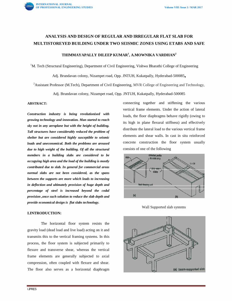
elements and shear walls. In cast in situ reinforced
concrete construction the floor system usually
consists of one of the following
Wall Supported slab systems
ANALYSIS AND DESIGN OF REGULAR AND IRREGULAR FLAT SLAB FOR
MULTISTOREYED BUILDING UNDER TWO SEISMIC ZONES USING ETABS AND SAFE
THIMMAYAPALLY DILEEP KUMAR1, A.MOWNIKA VARDHAN2
1M. Tech (Structural Engineering), Department of Civil Engineering, Vishwa Bharathi College of Engineering
Adj. Brundavan colony, Nizampet road, Opp. JNTUH, Kukatpally, Hyderabad-500085, 2Assistant Professor (M.Tech), Department of Civil Engineering, MVR College of Engineering and Technology,
Adj. Brundavan colony, Nizampet road, Opp. JNTUH, Kukatpally, Hyderabad-500085

INTERNATIONAL JOURNAL OF PROFESSIONAL ENGINEERING STUDIES Volume VIII /Issue 3 / MAR 2017
IJPRES
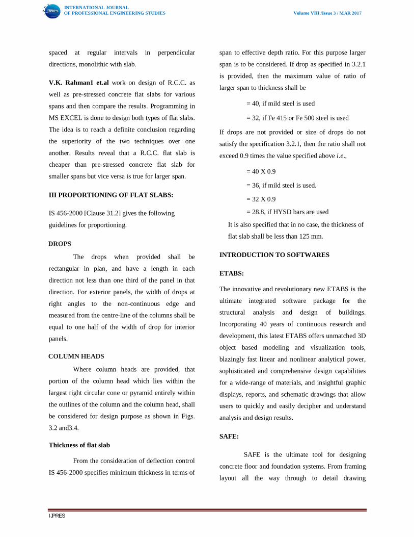
Beam Supported Slab System
Two way ribbed (waffle) slab system
Flat Slab Systems
RC slabs with long spans extended over several bays
and only supported by columns, without beams
known as flat slab. Flat slab system is very simple to
construct and is efficient in that it requires the
minimum building height for a given number of
stories. Such structure contains large bending
moment and vertical forces occur in a zone of
supports. This gives a very efficient structure which
minimizes material usages and decreases the
economic span range when compared to reinforced
concrete. Post-tensioning improves the structural
behaviour of flat slab structure considerably. This is
more acceptable concept to many designers. It is
adopted in some office buildings.
Drop Panels: The 'drop panel' is formed by the local
thickening of the slab in the neighbourhood of the
supporting column. Drop panels or simply drops are
provided mainly for the purpose of reducing shear
stress around the column supports.
Column Capital: The column capital or column head
provided at the top of a column is intended primarily
to increase the capacity of the slab to resist punching
shear. The flaring of the column at top is generally
done such that the plan geometry at the column head
is similar to that of the column.
Drop panel and column capital
Types of FLAT SLAB:
1. FLAT PLATE
2. FLAT PLATE WITH COLUMN HEAD OR
CAPITAL
INTERNATIONAL JOURNAL OF PROFESSIONAL ENGINEERING STUDIES Volume VIII /Issue 3 / MAR 2017
IJPRES
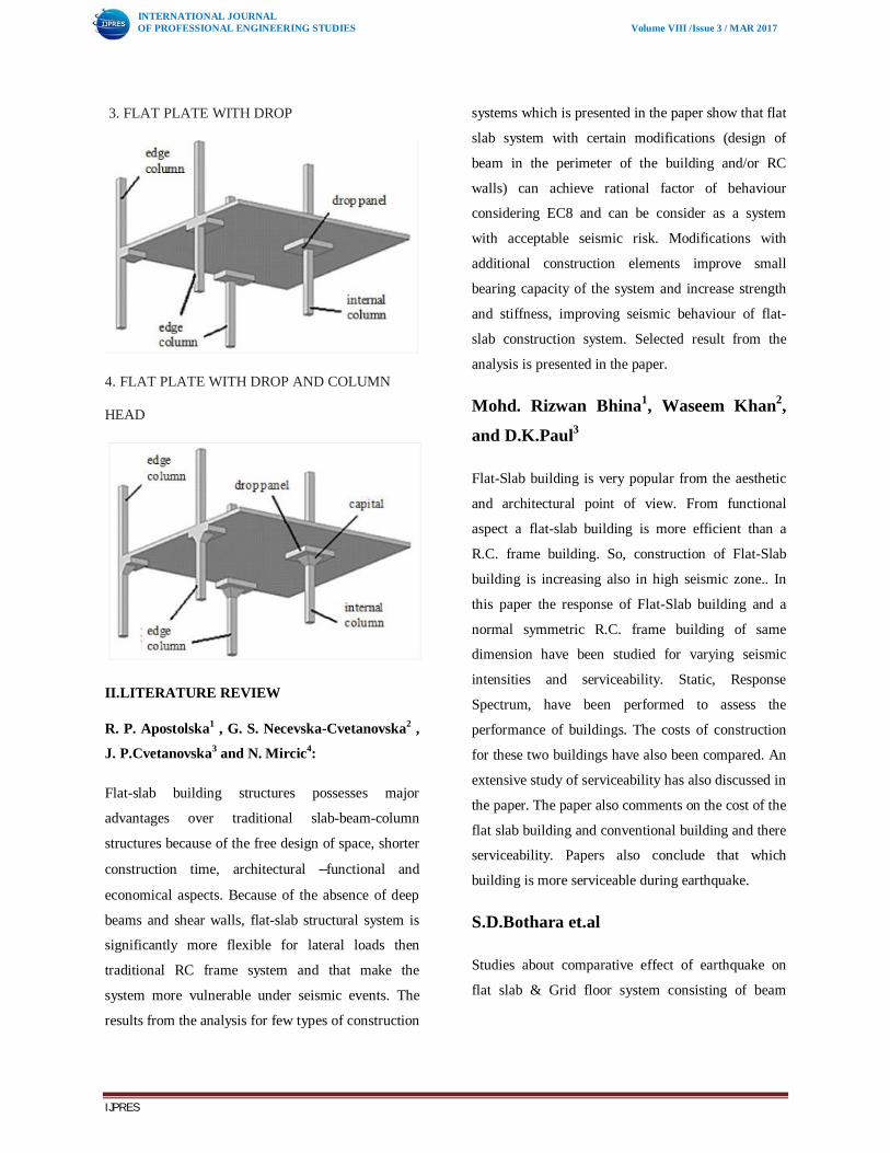
3. FLAT PLATE WITH DROP
4. FLAT PLATE WITH DROP AND COLUMN
HEAD
II.LITERATURE REVIEW
R. P. Apostolska1 , G. S. Necevska-Cvetanovska2 ,
J. P.Cvetanovska3 and N. Mircic4:
Flat-slab building structures possesses major
advantages over traditional slab-beam-column
structures because of the free design of space, shorter
construction time, architectural –functional and
economical aspects. Because of the absence of deep
beams and shear walls, flat-slab structural system is
significantly more flexible for lateral loads then
traditional RC frame system and that make the
system more vulnerable under seismic events. The
results from the analysis for few types of construction
systems which is presented in the paper show that flat
slab system with certain modifications (design of
beam in the perimeter of the building and/or RC
walls) can achieve rational factor of behaviour
considering EC8 and can be consider as a system
with acceptable seismic risk. Modifications with
additional construction elements improve small
bearing capacity of the system and increase strength
and stiffness, improving seismic behaviour of flat-
slab construction system. Selected result from the
analysis is presented in the paper.
Mohd. Rizwan Bhina1, Waseem Khan2,
and D.K.Paul3
Flat-Slab building is very popular from the aesthetic
and architectural point of view. From functional
aspect a flat-slab building is more efficient than a
R.C. frame building. So, construction of Flat-Slab
building is increasing also in high seismic zone.. In
this paper the response of Flat-Slab building and a
normal symmetric R.C. frame building of same
dimension have been studied for varying seismic
intensities and serviceability. Static, Response
Spectrum, have been performed to assess the
performance of buildings. The costs of construction
for these two buildings have also been compared. An
extensive study of serviceability has also discussed in
the paper. The paper also comments on the cost of the
flat slab building and conventional building and there
serviceability. Papers also conclude that which
building is more serviceable during earthquake.
S.D.Bothara et.al
Studies about comparative effect of earthquake on
flat slab & Grid floor system consisting of beam
INTERNATIONAL JOURNAL OF PROFESSIONAL ENGINEERING STUDIES Volume VIII /Issue 3 / MAR 2017
IJPRES
spaced at regular intervals in perpendicular
directions, monolithic with slab.
V.K. Rahman1 et.al work on design of R.C.C. as
well as pre-stressed concrete flat slabs for various
spans and then compare the results. Programming in
MS EXCEL is done to design both types of flat slabs.
The idea is to reach a definite conclusion regarding
the superiority of the two techniques over one
another. Results reveal that a R.C.C. flat slab is
cheaper than pre-stressed concrete flat slab for
smaller spans but vice versa is true for larger span.
III PROPORTIONING OF FLAT SLABS:
IS 456-2000 [Clause 31.2] gives the following
guidelines for proportioning.
DROPS
The drops when provided shall be
rectangular in plan, and have a length in each
direction not less than one third of the panel in that
direction. For exterior panels, the width of drops at
right angles to the non-continuous edge and
measured from the centre-line of the columns shall be
equal to one half of the width of drop for interior
panels.
COLUMN HEADS
Where column heads are provided, that
portion of the column head which lies within the
largest right circular cone or pyramid entirely within
the outlines of the column and the column head, shall
be considered for design purpose as shown in Figs.
3.2 and3.4.
Thickness of flat slab
From the consideration of deflection control
IS 456-2000 specifies minimum thickness in terms of
span to effective depth ratio. For this purpose larger
span is to be considered. If drop as specified in 3.2.1
is provided, then the maximum value of ratio of
larger span to thickness shall be
= 40, if mild steel is used
= 32, if Fe 415 or Fe 500 steel is used
If drops are not provided or size of drops do not
satisfy the specification 3.2.1, then the ratio shall not
exceed 0.9 times the value specified above i.e.,
= 40 X 0.9
= 36, if mild steel is used.
= 32 X 0.9
= 28.8, if HYSD bars are used
It is also specified that in no case, the thickness of
flat slab shall be less than 125 mm.
INTRODUCTION TO SOFTWARES
ETABS:
The innovative and revolutionary new ETABS is the
ultimate integrated software package for the
structural analysis and design of buildings.
Incorporating 40 years of continuous research and
development, this latest ETABS offers unmatched 3D
object based modeling and visualization tools,
blazingly fast linear and nonlinear analytical power,
sophisticated and comprehensive design capabilities
for a wide-range of materials, and insightful graphic
displays, reports, and schematic drawings that allow
users to quickly and easily decipher and understand
analysis and design results.
SAFE:
SAFE is the ultimate tool for designing
concrete floor and foundation systems. From framing
layout all the way through to detail drawing

INTERNATIONAL JOURNAL OF PROFESSIONAL ENGINEERING STUDIES Volume VIII /Issue 3 / MAR 2017
IJPRES
production, SAFE integrates every aspect of the
engineering design process in one easy and intuitive
environment. SAFE provides unmatched benefits to
the engineer with its truly unique combination of
power, comprehensive capabilities, and ease-of-use.
IV MODEL IN ETABS AND SAFE:
ETABS:
SAFE:
EXPORT TO SAFE
CELLER FLOOR PLAN IN SAFE
DESIGN OUT PUT:
PUNCHING SHEAR:
Punching shear: Max of =0.9885 which is less than 1 safe
BENDING MOMENT IN THE STRIPS
AREA OF STEEL ALONG THE STRIPS Y- AXIS

INTERNATIONAL JOURNAL OF PROFESSIONAL ENGINEERING STUDIES Volume VIII /Issue 3 / MAR 2017
IJPRES
AREA OF STEEL ALONG THE STRIP X-AXIS
V DRAWINGS:
FOUNDATION DETAILS:
CELLAR PLAN:
COLUMN DETAILS:

INTERNATIONAL JOURNAL OF PROFESSIONAL ENGINEERING STUDIES Volume VIII /Issue 3 / MAR 2017
IJPRES
FLOOR PLAN:
VI RESULTS:
STRIP FORCES
FOUNDATION REACTIONS:
DESIGN OF FOUNDATION:

INTERNATIONAL JOURNAL OF PROFESSIONAL ENGINEERING STUDIES Volume VIII /Issue 3 / MAR 2017
IJPRES
DISPLACEMENT:
BEAM DESIGN: DESIGNED FOR CRITICAL
LOAD ONLY BEAM 40
COLUMN DESIGN:
CONCLUSIONS
1. Flat-slab building structures possesses major
advantages over traditional slab-beam-column
structures because of the free design of space, shorter
construction time, architectural –functional and
economical aspects.
2. Because of the absence of deep beams and shear
walls, flat-slab structural system is significantly more
flexible for lateral loads then traditional RC frame
system and that make the system more vulnerable
under seismic events.
3. The purely flat-slab RC structural system is
considerably more flexible for horizontal loads than
the traditional RC frame structures which contributes
to the increase of its vulnerability to seismic effects.
4. The critical moment in design of these systems is
the slab-column connection, i.e., the penetration force
in the slab at the connection, which should retain its
bearing capacity even at maximal displacements.

INTERNATIONAL JOURNAL OF PROFESSIONAL ENGINEERING STUDIES Volume VIII /Issue 3 / MAR 2017
IJPRES
5. The ductility of these structural systems is
generally limited by the deformability capacity of the
column-slab connection.
6. To increase the bearing capacity of the flat-slab
structure under horizontal loads, particularly when
speaking about seismically prone areas and limitation
of deformations, modifications of the system by
adding structural elements are necessary.
REFERENCE:
[1] ISSN 2321-6905 (Paper) IJSEAT, Vol 4, Issue 2
,2016 “Analysis and Design of Flat Slabusing Etabs
Software” by B. Anjaneyulu et al.
[2] Sunayana Varma , B. Venugopal, K. Karthikeyan
International Journal of Civil Engineering and
Technology (IJCIET), ISSN 2321 –919X(Online),
Volume 2, Issue 8, August (2014)
[3] Mahdi hosseini , Ahmed najim Abdullah
alaskari,Prof.N.V.RamanaRao, International Journal
of Civil Engineering and Technology (IJCIET), ISSN
0976 –6316(Online), Volume 5, Issue 8, August
(2014).
[4] CSI, (2011), extended 3D analysis of building
structures (ETABS), Computers and Structures Inc.,
USA
[5] IS: 1893 (Part 1), (2002), Indian Standard Criteria
for Earthquake Resistant Design of Structures,
Bureau of Indian Standards, New Delhi.
[6] IS: 456:2000, Indian Standard Code of Practice
for Plain and Reinforced Concrete, Bureau of Indian
Standards, New Delhi.
[7] The other code books referred for this project are,
SP 16 (design aids for IS 456), IS 875 – Part I, II, III,
V.
[8] Mahdi hosseini , Ahmed najim Abdullah
alaskari,Prof.N.V.RamanaRao, International Journal
of Civil Engineering and Technology (IJCIET), ISSN
0976 –6316(Online), Volume 5, Issue 8, August
(2014).