analysis and development of fail-operational automotive...
TRANSCRIPT
Analysis and Development of Fail-Operational Automotive
Mechatronic Systems
Stephan Reinhofer1, Markus Ernst
1, Jürgen Fabian
1, and Adam Schnellbach
1
1Graz University of Technology, Institute of Automotive Engineering,
Inffeldgasse 11/II, 8010 Graz, Austria
Abstract: Ongoing advances in mechatronic components and power electronics help to improve control
systems within automotive applications. New developed or designed components enable more efficient system
architectures and control. The management of several parameters of future drive architectures, such as high
torque and power output, high system efficiency, low mass, low energy consumption, very low exhaust gas
emissions, and low costs is essential for future propulsion concepts. Based on these development trends,
mechatronic systems within automotive engineering are gaining more and more importance. At the same time,
quality and safety requirements become challenging for automotive manufacturers as well as their suppliers
regarding the reduction of the initial risk and increase of component reliability in a high degree. Therefore,
safety-relevant aspects in the development of modern mechatronic systems have to be considered thoroughly. The
high number of technical properties and complex connections of mechatronics systems in the development of
modern vehicles are very challenging for state-of-the-art analysis methods. For this reason, new and
innovational safety concepts are required to optimize existing safety concepts using conventional components
and methods in combination.
This paper includes a detailed comparison of different analysing methods to identify systematic and random
failures, as well as safety standards such as IEC 61508 (Functional Safety of
Electrical/Electronic/Programmable Electronic Safety-related Systems) and ISO 26262 (Road vehicles –
Functional safety). To fulfil safety standards nowadays for complex mechatronic systems, several different
analysis methods have to be applied. Only the connection of a safe fault recognition with a safe fault reaction
enables a system to avoid harmful consequences. Regarding product development, there is an ongoing change
from routine tests (durability tests) to testing selected parts of a safety function (fault injection tests). How action
is taken is changing, with a trend towards a further development of IT tools, supporting functional safe systems
holistically, including hazard analysis and risk assessment, integrated system analysis of systematic and random
failures, and hardware metrics. The publication closes with an overview of a functional safety concept and
presents an outlook to future trends of safety systems analysis
Keywords: Failure Mode and Effects Analysis FMEA, Fault Tree Analysis FTA, IEC 61508, ISO 26262,
Automotive Safety Integrity Level ASIL, Fail-Operational, Automotive Mechatronic Systems, Drive Architectures.
1. Introduction
The increasing amount of electronic components and use of electro-mechanical actuators in the automotive
sector raises reliability and system integrity needs. As removing mechanical back-up systems is more and more
considered, safety related electronic structures must be designed to work under any circumstances. As failure
rates for electronic components are higher than for mechanical ones, the skill lies in creating reliable structures
out of less reliable elements. Redundancy in software and hardware are the keys to overcome reliable products
from single point failures. A combination of these approaches allows a creation of a structural design, which can
deal with a restricted number of failures [1].
ISBN 978-93-84422-37-0
2015 International Conference on Advances in Software, Control and Mechanical Engineering
(ICSCME'2015)
Antalya (Turkey) Sept. 7-8, 2015 pp. 1-7
http://dx.doi.org/10.17758/UR.U0915115 41

The use of electronic components in safety related systems in automotive applications is steadily increasing.
In order to achieve an equal or higher safety level as with pure mechanic components, these components are
designed with a fail-safe redundancy level. Fail-safe signifies that the component is transferred into an active or
passive safe state when a failure occurs. In case of a passive safe state, all concerning interfaces are silenced in
order to exclude any interference of peripherals or other functions. On one hand fail-safe means a protection of
the remaining system from disturbance, but on the other hand the availability of the component suffers from this
technique. Dependent on the implemented function of the component, the function might have a very high
priority for the system, and therefore its availability is essential [1], [2].
For driving assistance systems, electronic components are essential parts which allow fast controlling of the
actuators. The state of the art for saving assistance functions is fault tolerance at fail-safe level. On assumptions
that the average driver can control the car without the assistance systems, the fail-safe level is completely
appropriate. Considering that the younger generation never had experience with driving without electronic
assistance systems and are completely accustomed to it, moving to fault tolerant topologies is recommended [2],
[3].
The origin of fail-operational architectures lies in aeronautic engineering. Aviation needed technical
implementations which provide functionality under any circumstances during the whole flight. Different from
other industry sectors, failure in safety critical functions could not be solved with transition to a safe state. As
the safe state of an airplane is reached when it is landed, sending functions which keep the plane operational
while flying to a silent state do not increase the safety of the plane. Strategies needed to be applied to keep vital
functions operational at any cost. Precautions had to be taken in order to reduce the risk of losing essential
functions to an acceptable low level. These precautions were the implementation of redundancy in order to
achieve operational behaviour even after several failures of the same item [1], [4].
2. Common Strategies for Fail-Operational Systems
Whether a fail-operational level or a fail-silent level of fault tolerance is required, redundancy is mostly the key
of implemention. A classic distinction into software and hardware related areas leads to following strategies:
Static Hardware redundancy
Dynamic Hardware redundancy
Static Software redundancy
Dynamic Software redundancy.
2.1. Static Hardware redundancy The most widespread hardware method is static redundancy combined with a majority voting, also called
M-n-Systems. Within this method, critical elements of a safety related item are multiplied. They are fed with the
same inputs and provide, if functionally correct, the same output. To determine if an output is correct or not, all
outputs from the elements are fed to a voter. The voter then compares the outputs of the multiplied elements and
assumes that the output given by the majority is the correct one. Only the result of the majority voting is
forwarded to the item which needs the information. Possible wrong outputs are suppressed as long as not the
majority of the elements deliver wrong outputs at the same time. Elements which deliver repeatedly wrong
outputs can be masked and excluded from the voting. In this case, a degradation of the fault-tolerance level takes
place, as depicted in Fig. 1 [1], [5].
Depending on the required tolerance level of the application, critical elements are doubled, tripled, or
quadrupled to stay operational after one, two, or even three failures of the same item. In principle, any amount of
elements and majority number is possible in M-n-Systems, where m describes the limit needed for the majority,
and n the amount of elements used. The minimum set for majority voting, a 2 out of 3 system, is also called
Triple Modular Redundancy (TMR) and can still operate after one element fails. After one failure, TMR
degrades to a Duplex System where the Voter only compares the outputs of the elements instead of a majority
voting. If both outputs are equal, a correct state of the elements is assumed. The Duplex system needs to shut
down when another element fails, since there is no guarantee if the remaining single element gives right values
or not. Through a plausibility check it is possible to prove if the value is within a realistic range. Element failures
http://dx.doi.org/10.17758/UR.U0915115 42

which manipulate output values to a level that normally could occur in reality are not detectable. In safety related
applications, this insecurity cannot be accepted [5], [7].
Fig. 1: Static hardware redundancy approach with voter topologies [1], [6].
A weak spot of M-n topologies are occurring failures in the voter itself: if the voter fails, the whole item
fails. To overcome this situation, a Duo-Duplex system with two independent items can be used. Also topologies
that triple the voter, a so called triple-triple redundancy, are a promising way of overcoming voter failures [1],
[7].
2.2. Dynamic Hardware redundancy A downside of M-n systems is the simultaneously outwearing of parallel elements and the increasing
power consumption with every added element. The redundant elements are running for the same amount of time
and experience the same extent of ageing. An approach to improve the unnecessarily outwearing is given by a
dynamic reconfiguration strategy. This strategy has only one element running at a time operating and the other
redundant elements are shut down (cold standby). A fault detection system has to monitor the operating element
whether its function is correct or not. If the element fails, a sleeping redundant element is turned on and replaces
the defect one. This of course, takes some reconfiguration time which is a critical factor for the system recovery.
Another crucial factor is the fault detection routine by itself since this system works only as good as its fault
detection does. Using fail-silent elements, which do not give any output when an internal failure occurs,
simplifies the fault detection [1], [5].
2.3. Static Software redundancy N-version programming is an analogue approach in software as M-n systems implementation in hardware.
Several code routine alternatives are programmed independently for the same specification. The main and the
alternative software are executed simultaneously, their outputs are compared and only a correct value is
forwarded. To supply independence, other programming teams, other software languages, and other compilers
are used. This increases the costs, complicates documentation, and maintenance of the item. Analogous to the
hardware, this diversity concept protects the software from systematic failures. Only failures in the specification
are not covered [1], [5], [7].
2.4. Dynamic Software redundancy Recovery blocks are a dynamic redundancy concept in software. Within a recovery block, several code
alternatives realizing the same function are offered, same as in n-version programming. Instead of running all
alternatives simultaneously, only one alternative runs at a time and its output is checked afterwards by an
acceptance test. If the acceptance test detects an error, the previous state is restored and the next code alternative
is chosen. When there are no more alternatives left, the whole software item fails. As a protection against
failures resulting from transient hardware failures, the same code alternative can be repeated.
Problems may arise through intercommunication of a running code alternative with other processes
outside the recovery block followed up by a failed acceptance test. Other processes need to be informed about
the corrupted outcome of the process and their received data, otherwise corrupted data is assumed to be correct,
which leads to a distribution of the failure within the system, as shown in Fig. 2 [1], [7].
active
passive
http://dx.doi.org/10.17758/UR.U0915115 43
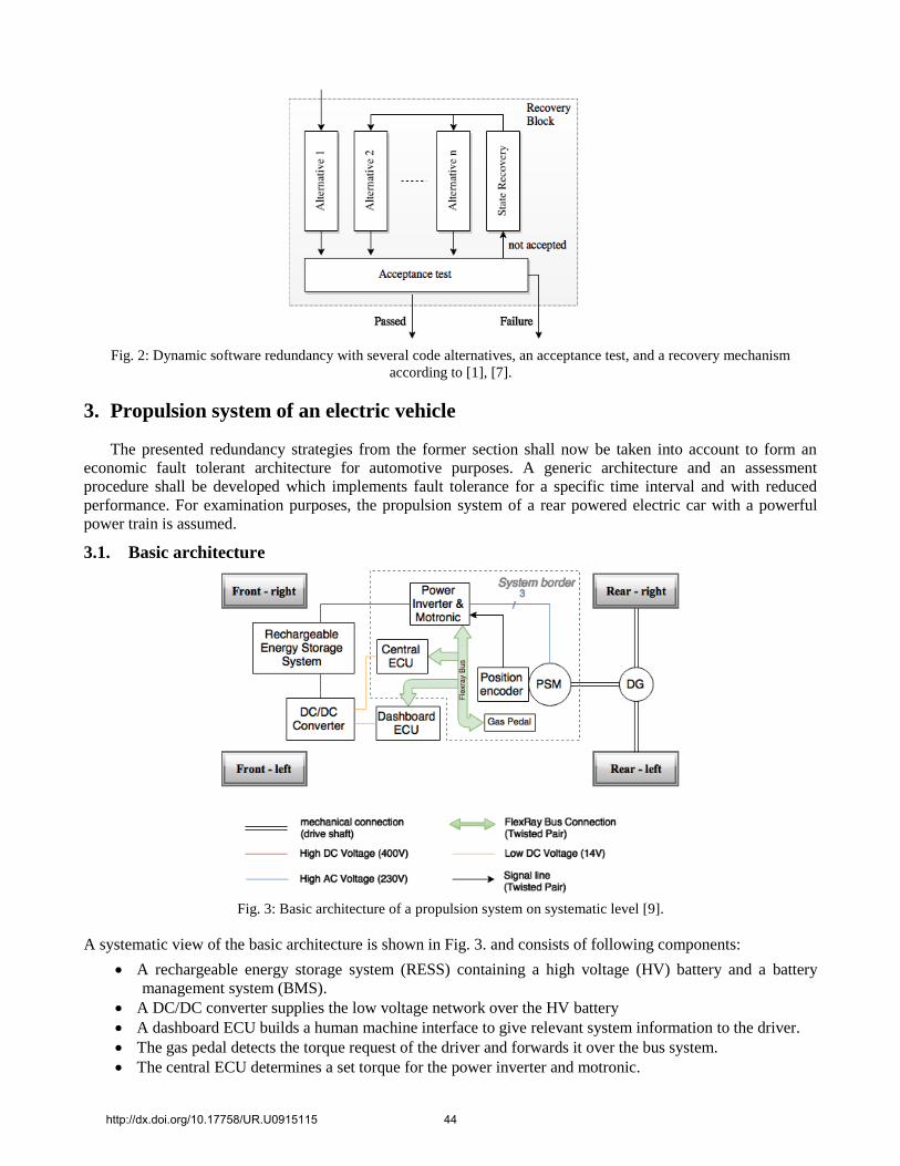
Fig. 2: Dynamic software redundancy with several code alternatives, an acceptance test, and a recovery mechanism
according to [1], [7].
3. Propulsion system of an electric vehicle
The presented redundancy strategies from the former section shall now be taken into account to form an
economic fault tolerant architecture for automotive purposes. A generic architecture and an assessment
procedure shall be developed which implements fault tolerance for a specific time interval and with reduced
performance. For examination purposes, the propulsion system of a rear powered electric car with a powerful
power train is assumed.
3.1. Basic architecture
Fig. 3: Basic architecture of a propulsion system on systematic level [9].
A systematic view of the basic architecture is shown in Fig. 3. and consists of following components:
A rechargeable energy storage system (RESS) containing a high voltage (HV) battery and a battery
management system (BMS).
A DC/DC converter supplies the low voltage network over the HV battery
A dashboard ECU builds a human machine interface to give relevant system information to the driver.
The gas pedal detects the torque request of the driver and forwards it over the bus system.
The central ECU determines a set torque for the power inverter and motronic.
http://dx.doi.org/10.17758/UR.U0915115 44

The position encoder provides angle information of the actual rotor position.
The power inverter and motronic performs a field orientated closed loop control of the machine.
The permanent excited synchronous machine (PSM) produces the output torque given to the rear axle
over the differential gear (DG).
The signal flow from the driver to the electric machine, as long as no error occurs, can be seen in Fig. 4:
Fig. 4: Signal flow from the driver torque demand to the machine output [9].
As electric machines are connected to the tyres with no clutch in-between, there is no mechanical way to
disconnect the motor from the drive axle. Fluctuations of torque or too high/low engine break therefore directly
affect the vehicle behaviour and can lead to a loss of stability. The basic architecture must provide fail-safe
behaviour to avoid hazards caused by too high/low engine break.
Any component failing inside the signal flow leads to a loss of the propulsion system and a transition to a
passive safe-state of the same. The low availability of this system is obvious and also several scenarios were
identified with the help of a HARA (Hazard Analysis and Risk Assessment) where avoiding accidents highly
relies on correct function of the propulsion system. An extension of the basic architecture in order to achieve
fail-operational behaviour is intended to suppress accidents caused by a loss of the propulsion system. For
instance overtaking on a country road with oncoming traffic or getting in lane on an intersection with no traffic
light regulations are critical if the propulsion is lost while carrying out these manoeuvres.
3.2. Fail operational architecture To overcome the safety issue in case of loss of the propulsion system, the basic architecture components were
extended or replaced to provide a fail-operational behaviour as shown in Fig. 5. The components were revised as
follows:
The DC/DC Converter is doubled to avoid a loss of the energy supply of the low voltage network.
The gas pedal is retrofitted to a Triple Modular Redundancy (TMR) which implements a 2 out of 3
majority voting.
The Bus System is upgraded to a dual-channel Flexray System which transfers the same data over two
separated twisted pair connections.
The central ECU is now a fail-operational unit made out of two fail-silent ECUs with hot standby. The
ECU 2 always has the same state as the ECU 1 and an intelligent switch puts the signals of ECU 2 on the
output as soon as the error detection does not receive a signal from ECU 1.
The electric machine is exchanged to a dual stator winding 6-phase PSM. This machine type consists of
two 3-phase subsystems which are separately controlled by two inverters. This leads to a higher output
torque while no fault is present and to a nominal output torque of 40% in case of only one remaining
inverter [8].
http://dx.doi.org/10.17758/UR.U0915115 45
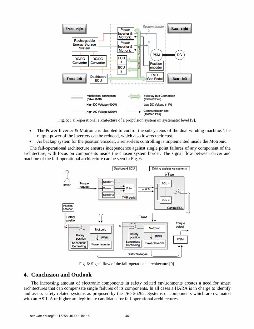
Fig. 5: Fail-operational architecture of a propulsion system on systematic level [9].
The Power Inverter & Motronic is doubled to control the subsystems of the dual winding machine. The
output power of the inverters can be reduced, which also lowers their cost.
As backup system for the position encoder, a sensorless controlling is implemented inside the Motronic.
The fail-operational architecture ensures independence against single point failures of any component of the
architecture, with focus on components inside the chosen system border. The signal flow between driver and
machine of the fail-operational architecture can be seen in Fig. 6.
Fig. 6: Signal flow of the fail-operational architecture [9].
4. Conclusion and Outlook
The increasing amount of electronic components in safety related environments creates a need for smart
architectures that can compensate single failures of its components. In all cases a HARA is in charge to identify
and assess safety related systems as proposed by the ISO 26262. Systems or components which are evaluated
with an ASIL A or higher are legitimate candidates for fail-operational architectures.
http://dx.doi.org/10.17758/UR.U0915115 46
The proposed architecture in this paper provides fail-operational behaviour with at least 40% nominal
output torque in case of a fault of the PSM or one of the Power Inverter & Motronic blocks. In all other single
point failure scenarios the full performance is still available for the driver. Moreover, a slightly increased output
torque of 5% is sustained by the six phase machine compared to a three phase machine of the same size [8].
Future research should include an economic assessment of the fail-operational architecture. Not only
additional costs of the components need to be incorporated, but also the time and effort required for identifying
the vulnerabilities of the architecture. The highest potential for lowering component cost surely lies in reduced
performance for a determined amount of time after one failure which only provides a limp home state rather than
full performance until the next fault. With this approach, cheaper components could be implemented as
redundant backup to the architecture.
5. References
[1] S. Reinhofer, M. Ernst, and J. Fabian, “Strategies for the Development and Analysis of Functional Safe Automotive
Mechatronic Systems,“ in Proc. WMSCI Conf., 2015.
[2] K. Borgeest, Elektronik in der Fahrzeugtechnik. Hardware, Software, Systeme und Projektmanagement, 3rd ed.
Springer Vieweg, 2014
http://dx.doi.org/10.1007/978-3-8348-2145-4.
[3] K. Reif, Automobilelektronik - Eine Einführung für Ingenieure, 5th ed. Springer Vieweg, 2014.
[4] H. Flühr, Avionik und Flugsicherungstechnik, Springer, 2010.
http://dx.doi.org/10.1007/978-3-642-01612-7
[5] R. Isermann, Mechatronische Systeme, 2nd ed. Springer, 2008.
[6] P. Nenninger, “Vernetzung verteilter sicherheitsrelevanter Systeme im Kraftfahrzeug,” Ph.D. thesis, University of
Karlsruhe, Germany, 2007.
[7] T. Klöber and O. Spinczyk, “Fehlertoleranz in eingebetteten Systemen,” Department of Computer Science 4, Friedrich-
Alexander-Universtität, Germany, 2006.
[8] M. Barcaro, N. Bianchi, and F. Magnussen. “Six-phase supply feasibility using a PM fractional-slot dual winding
machine,” in Energy Conversion Congress and Exposition (ECCE), 2010 IEEE, 2010.
[9] S. Reinhofer, “Fail-Operational Architectures for electric Drives,” Master’s thesis, Graz University of Technology,
Institute of Automotive Engineering, Austria, 2015.
http://dx.doi.org/10.17758/UR.U0915115 47