analysis and evaluation of electric motor
TRANSCRIPT
26th Aachen Colloquium Automobile and Engine Technology 2017 223
Analysis and Evaluation of Electric Motor Topologies for a Kinematic-Electric 48 Volt Powertrain Daniel Butterweck, M.Sc., Dipl.-Ing. Marco Hombitzer, Univ.-Prof. Dr.-Ing. habil. Dr. h.c. Kay Hameyer Institute of Electrical Machines (IEM), RWTH Aachen University, Aachen, Germany
Summary
For a broad market introduction of electric- and hybrid electric vehicles, the investment costs of the traction battery are still an obstacle. Furthermore, the potential boost and electric recuperation can't be fully utilized without a lifetime reduction of the electrochemical storage system [1]. In this paper, the development of a powertrain consisting of an infinite variable transmission and an electric high speed motor with an integrated flywheel which tackles these challenges, is described. The advantages and disadvantages of several electric motor topologies for such a system are discussed and results of the motor design process are presented.
1 Introduction
Mobility is an integral part of the daily life. However, it is also one of the biggest causes of greenhouse gases emission. The road transportation sector accounts for 17.24 % of the total CO2 emissions of Germany in 2015. From this, more than 70 % are formed by passenger cars and light commercial vehicles [2]. Therefore, research and development efforts in these fields of applications are necessary to make decisive contributions to the social and political objectives such as reducing the dependency on fossil fuels, climate-damaging emissions and securing mobility in the near future. In the area of drivetrain development, a large number of complementary concepts and solutions are present. They range from so-called Mild to Full, Range Extended (REEV) and Plug-In Hybrid (PHEV) to Battery Electric Vehicles (BEV or EV), each with different degrees of electrification of the powertrain. Although an increasing share of these topologies in passenger cars and in mobile working machines has already been recorded, a broad market launch remains open largely due to the still high system costs. Despite steady progress in the development of the chemical energy storage, these will still have a decisive share in the system costs of an EV in the foreseeable future. In addition, state-of-the-art lithium-ion batteries are not suitable for high charging and discharging power, as they occur in everyday braking and acceleration maneuvers, without a reduction of lifetime. The boost and recovery capacities achievable today are thereby limited. As a result, the electric range of EVs and the possible emission-savings of HEVs remain behind the achievable potentials. The addition of the drive system to a flywheel store represents a promising alternative in order to be able to meet the required properties of high

224 26th Aachen Colloquium Automobile and Engine Technology 2017
energy and power density while at the same time increasing the service life of the entire drive train at low cost. The project "Kinelectric Drive" (promotion code 01MY14006B) performed in cooperation with GKN Driveline since January 2015 and funded by the German Federal Ministry of Economics and Energy with a total duration of 36 months aims at the development of such a kinetic-electric powertrain. When compared to the design of typical high-speed motors, additional constraints and requirements apply for the design of the flywheel motor. In this paper, different design aspects and motor topologies are discussed.
2 Kinetic Storage Systems
The principle to store energy in form of kinetic energy by utilizing the moment of inertia and the speed around an object's axis of rotation, is well known and used since decades [3].
The rotational Energy of a cylinder with homogeneous mass can be described as
12
14
14
with the moment of inertia , the angular speed ,the mass , the mass density ρ, the radius , the length and the rotational speed of the cylinder. As can be seen, the rotational energy flow can be controlled by the speed of the rotor. This is usually achieved by an electrical machine coupled to the rotor. If the machine is operated as a motor, the speed of the rotor increases and electric energy is converted into kinetic energy. Visa versa, kinetic energy is converted into electric energy when the rotor is slowed by the electrical machine acting as a generator. Compared to electrochemical storage systems, flywheels have advantages in properties such as:
1. Long lifetime (mainly limited by the motor's bearing lifetime). Other than batteries, flywheels show little to no cyclic and calendric ageing.
2. Low costs, 3. High power density.
Due to this, the technology is suitable for applications with a high number of cycles, where energy doesn't need to be stored for a longer period of time and for applications with high power peaks. Therefore, flywheel storage systems are often used for grid energy storage or the smoothing of grid frequency due to power fluctuations. In the last decades, flywheel storage technology is more and more emerging into the transportation sector. Several systems have successfully been developed and implemented in public transportation, mainly hybrid buses. The developed systems have correspondingly high power levels and energy contents. The "highFly" project of Traktionssysteme Austria GmbH, developed in cooperation with the Graz University of Technology in 2015, has a usable stored mechanical energy of 900 Wh and a peak power of 145 kW (700 Volt on-board voltage). The rotor of the five-phase synchronous reluctance motor is made of high-strength cobalt-alloyed electrical steel. The total energy storage system including the inverter has a
26th Aachen Colloquium Automobile and Engine Technology 2017 225
mass of 300 kg [4]. In 2014, GKN Hybrid Power announced the acquisition of the Williams Hybrid Power technology previously used in Formula One. Since then, it has been modified for the use in public transportation and is now known as "Gyrodrive". In this system, a composite material flywheel which can store up to 500 Wh and deliver 120 kW in combination with a permanent magnet motor is used. The magnets are embedded into the flywheel composite material. From 2014 to 2016, this system was installed in 500 London buses [5]. Increasing activities can also be noted for private transportation. Under the german "Neue Energien 2020" program of the Climate and Energy Fund, a storage system with an energy content of 270 kJ and a peak power of 20 kW is developed for use in hybrid and electric vehicles with on-board electrical voltages of 300 V - 400 V. The rotor, also made of cobalt-alloyed electrical steel, is mounted by a combination of conventional rolling bearings and a supportive magnetic bearing [6]. In 2009, a flywheel system with a mechanical power path was developed by "Flybrid Systems" for the use in Formula One. The mechanical power path is realized by a continuously-variable transmission by "Torotrak". The Flybrid system has a usable energy of 111 Wh and delivers up to 60 kW. The maximum speed of the composite flywheel is 64,500 rpm and the entire system has a weight of only 25 kg [7]. In 2011, Jaguar used a similar system from Flybrid Automotive in a Jaguar XF with a system weight of 65 kg, 120 Wh and 60,000 rpm. A similar system was later used in a Volvo S60. By incorporating such systems into the conventional drivetrains, fuel savings of around 20% have been reported [7].
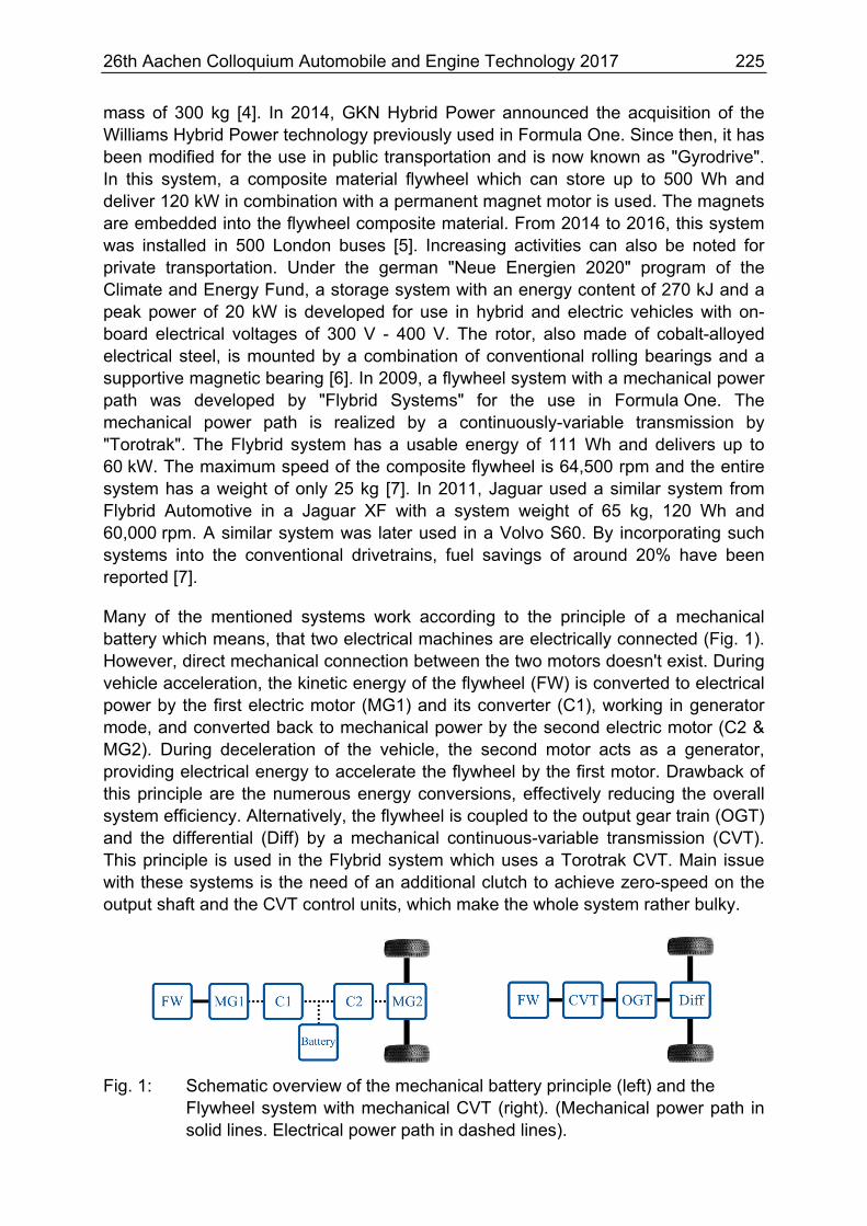
Many of the mentioned systems work according to the principle of a mechanical battery which means, that two electrical machines are electrically connected (Fig. 1). However, direct mechanical connection between the two motors doesn't exist. During vehicle acceleration, the kinetic energy of the flywheel (FW) is converted to electrical power by the first electric motor (MG1) and its converter (C1), working in generator mode, and converted back to mechanical power by the second electric motor (C2 & MG2). During deceleration of the vehicle, the second motor acts as a generator, providing electrical energy to accelerate the flywheel by the first motor. Drawback of this principle are the numerous energy conversions, effectively reducing the overall system efficiency. Alternatively, the flywheel is coupled to the output gear train (OGT) and the differential (Diff) by a mechanical continuous-variable transmission (CVT). This principle is used in the Flybrid system which uses a Torotrak CVT. Main issue with these systems is the need of an additional clutch to achieve zero-speed on the output shaft and the CVT control units, which make the whole system rather bulky.
Fig. 1: Schematic overview of the mechanical battery principle (left) and the Flywheel system with mechanical CVT (right). (Mechanical power path in solid lines. Electrical power path in dashed lines).
226 26th Aachen Colloquium Automobile and Engine Technology 2017
3 KinelectricDrive
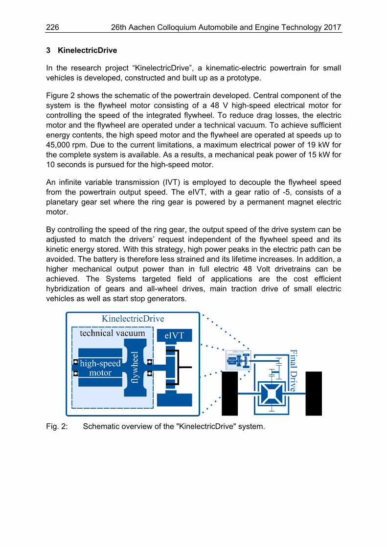
In the research project “KinelectricDrive”, a kinematic-electric powertrain for small vehicles is developed, constructed and built up as a prototype.
Figure 2 shows the schematic of the powertrain developed. Central component of the system is the flywheel motor consisting of a 48 V high-speed electrical motor for controlling the speed of the integrated flywheel. To reduce drag losses, the electric motor and the flywheel are operated under a technical vacuum. To achieve sufficient energy contents, the high speed motor and the flywheel are operated at speeds up to 45,000 rpm. Due to the current limitations, a maximum electrical power of 19 kW for the complete system is available. As a results, a mechanical peak power of 15 kW for 10 seconds is pursued for the high-speed motor.
An infinite variable transmission (IVT) is employed to decouple the flywheel speed from the powertrain output speed. The eIVT, with a gear ratio of -5, consists of a planetary gear set where the ring gear is powered by a permanent magnet electric motor.
By controlling the speed of the ring gear, the output speed of the drive system can be adjusted to match the drivers’ request independent of the flywheel speed and its kinetic energy stored. With this strategy, high power peaks in the electric path can be avoided. The battery is therefore less strained and its lifetime increases. In addition, a higher mechanical output power than in full electric 48 Volt drivetrains can be achieved. The Systems targeted field of applications are the cost efficient hybridization of gears and all-wheel drives, main traction drive of small electric vehicles as well as start stop generators.
Fig. 2: Schematic overview of the "KinelectricDrive" system.
26th Aachen Colloquium Automobile and Engine Technology 2017 227
4 Design of the flywheel storage system
For technical applications, the kinetic energy per volume of the cylinder is of particular importance. It can be described as
⋅14
⋅
This simple correlation already shows the necessity of high circumferential speeds for efficient storage of rotational energy by a flywheel. Since the mechanical
stress is linearly dependent on the circumferential speed, the mechanical design of such systems is a challenging task.
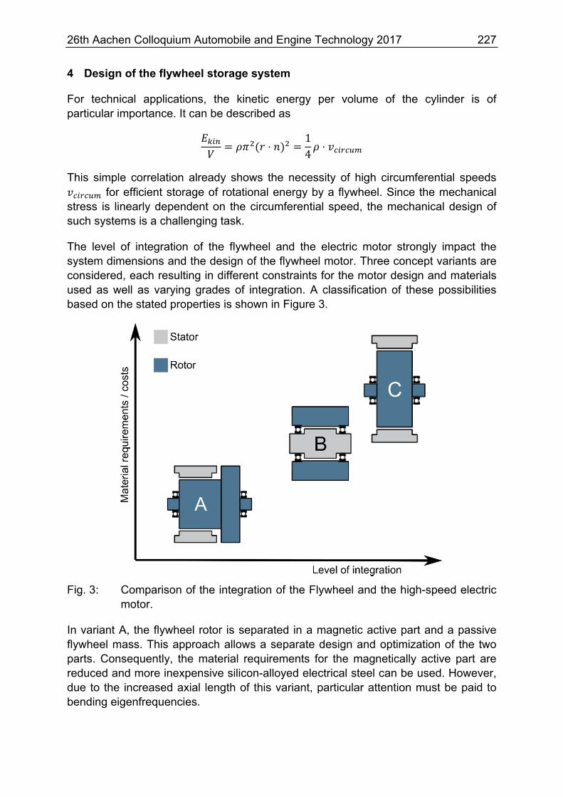
The level of integration of the flywheel and the electric motor strongly impact the system dimensions and the design of the flywheel motor. Three concept variants are considered, each resulting in different constraints for the motor design and materials used as well as varying grades of integration. A classification of these possibilities based on the stated properties is shown in Figure 3.
Fig. 3: Comparison of the integration of the Flywheel and the high-speed electric motor.
In variant A, the flywheel rotor is separated in a magnetic active part and a passive flywheel mass. This approach allows a separate design and optimization of the two parts. Consequently, the material requirements for the magnetically active part are reduced and more inexpensive silicon-alloyed electrical steel can be used. However, due to the increased axial length of this variant, particular attention must be paid to bending eigenfrequencies.

228 26th Aachen Colloquium Automobile and Engine Technology 2017
Variant B is an outer rotor concept which results in a higher level of integration. Since the rotating mass is located on the most outer diameter, highest kinetic energy densities can be achieved. It is therefore the most used variant in current flywheel systems such as GKN's Gyrodrive system. Due to the nature of the outer rotor variant, only simple cylinder shaped flywheel designs can be used. To form the magnetically active rotor of the machine, permanent magnets can be embedded into the flywheel made from fiber composite material. In the outer rotor concept, particular attention must be paid to the containment. For a given outer diameter of the motor, the available stator volume gets reduced, resulting in higher current densities for a given stator current. In combination with the reduced stator surface area, the heat dissipation also gets reduced, effectively leading to higher stator winding temperatures.
Variant C achieves the highest level of integration of the flywheel and the electrical motor. The design is identical to that of a conventional electric motor. The complete flywheel mass is formed by the magnetically active part of the rotor. The stator serves as an additional burst protection, reducing the requirements on the containment. In contrast to variant A however, a separate design of the two parts is not possible, inevitable leading to trade-offs in the design. As stated earlier, high energy densities are achieved by high circumferential speeds. In this concept, the magnetically active part has to withstand these high circumferential speeds as well. Therefore, soft magnetic materials with high yield strengths are required.
4.1 Soft magnetic materials for high-speed motors
The soft magnetic material is the central component for the magnetic flux-carrying cores in electrical machines and therefore has a major impact on the machines performance. From an electromagnetic point of view, the material can be classified by its magnetizability and the specific iron losses. The iron losses have a strong frequency, hence speed of the machine, and magnetic flux density dependency in common. With the ever-growing interest to further increase the machine speeds, the requirements for electrical steel rises. For the stator of the motor, the electromagnetic properties are of particular interest to achieve high efficiencies and power densities. The mechanical material properties are of minor interest. The material used for the rotor however, has to combine a high yield strength with low specific iron losses. This led to numerous material developments in the recent years. For a good machine design it's crucial to identify suitable soft magnetic materials tailored to the application.
For the flux guiding in electrical machines, mainly two alloys are of particular commercial interest. The most commonly used soft magnetic material is non-grain-oriented silicon iron (Fe-Si) with up to 3% of silicon content. Alternatively cobalt iron (Fe-Co) can be used. The alloying of cobalt to iron results in higher saturation flux densities than Fe-Si can achieve.

26th Aachen Colloquium Automobile and Engine Technology 2017 229
Several grades with differing magnetic and mechanical properties are available. Some of these grades and their properties given by the manufactures are listed in Tab. 1:
Grade Alloy Yield Strength Specific iron losses Voestalpine M250-35A
Si 440 MPa 2.35 W/kg (1.5 T, 50 Hz)
Thyssen Krupp NO20
Si 360 MPa 2.4 W/kg (1.5 T, 50 Hz) 43 W/kg (1.0 T, 1 kHz)
Thyssen Krupp M270-35A
Si 360 MPa 2.4 W/kg (1.5 T, 50 Hz) 80 W/kg (1.0 T, 1 kHz)
Thyssen Krupp 280-30 AP
Si 440 MPa 2.5 W/kg (1.5 T, 50 Hz) 62 W/kg (1.0 T, 1 kHz)
Vacuumschmelze VACODUR S Plus1
Co 400 MPa 3 W/kg (1.5 T, 50 Hz)
186 W/kg (1.5 T, 1 kHz) Vacuumschmelze
VACODUR S Plus2 Co 800 MPa
11.5 W/kg (1.5 T, 50 Hz) 349 W/kg (1.5 T, 1 kHz)
Tab. 1: Yield strength and specific total losses of different material grades. (1annealed for opt. magn. properties, 2annealed for opt. mech. properties)
The comparison of the different Fe-Si grades show similar specific total losses at a flux density of 1.5 T and a frequency of 50 Hz. For the application in high speed electrical drives, frequencies of 1 kHz and above are of particular interest. Here, thinner grades such as the Thyssen Krupps NO20 with only 0.2 mm lamination thickness show lower specific iron losses than thicker materials such as Thyssen Krupps 280-30 AP which has a lamination thickness of 0.3 mm. The yield strengths of the Fe-Si grades shown range from 360 MPa to 440 MPa of higher strength materials such as the 280-30 AP.
The Fe-Co materials listed are available in two different versions. The properties of the materials are altered by a final annealing. While the material which was annealed for optimum magnetic properties has a comparable yield strength and specific iron losses to the Fe-Si grades, the grade which was annealed for optimum mechanical properties has a significantly higher yield strength. However, this comes at the cost of higher iron losses. In addition, the Fe-Co grades shown have a cobalt content of 49% making the Fe-Co grades significantly more expensive when compared to the Fe-Si grades.
For the design of a kinematic-electric powertrain following concept C, high circumferential speeds of the magnetically active rotor are inevitable to reach the projected energy densities. This will require the use of Fe-Co alloys with optimized mechanical properties. Due to the significantly higher costs, the use of these materials does not seem to be appropriate for low-cost applications like the KinelectricDrive system. Instead, an integration of the flywheel and the electric motor following concept A is used in combination with a Fe-Si grade with higher yield strength. Thyssen Krupps 280-30 AP offers a good balance between yield strength and specific iron losses at high frequencies.

230 26th Aachen Colloquium Automobile and Engine Technology 2017
5 Electric High-Speed Motors for Kinetic-Electric Powertrains
Compared to the design of typical high-speed motors, additional constraints and requirements apply for the design of the flywheel motor. A low self-discharge rate of the flywheel is especially crucial, which is mainly influenced by the aerodynamic drag losses, bearing losses, losses of the rotational vacuum sealing and the no-load-losses of the electrical motor.
For the KinelectricDrive systems, the three most dominant motor topologies are considered. After the general design draft of the motors, 2D electromagnetic finite element simulations (FEM) are carried out to evaluate the motor performance over the whole speed and torque range. The mechanical strength is accounted for using 3D-finite element simulations. In the following, the advantages and disadvantages of these electric motor topologies are discussed. Results of the motor design are presented and the influence of the vacuum on the aerodynamic drag losses and the thermal conductivity is described.
5.1 Influence of the Technical Vacuum on the Motor Design
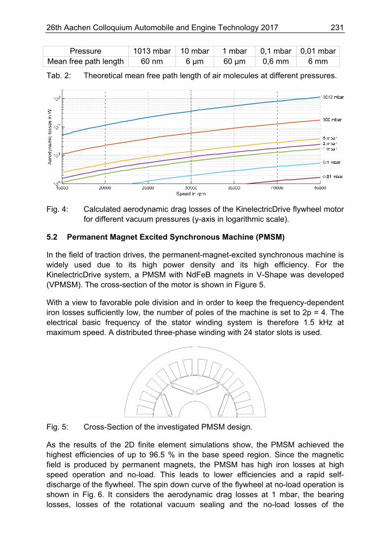
In order to reduce aerodynamic drag losses, the flywheel and the electric machine are operated in a technical vacuum. Depending on the pressure of the technical vacuum, the thermal convection is severely restricted and heat energy can mainly be transferred by radiation and conduction through the shaft and the bearings. As a result, the cooling of the electrical machine complicates itself. Finding the trade-off between low aerodynamic drag losses and a sufficient cooling of the machine is crucial. In Figure 4 the influence of the vacuum pressure on the aerodynamic drag losses at 80 °C is shown. At the maximum speed of 45,000 rpm, the aerodynamic drag losses at atmospheric pressure would be 1,100 Watts, which is around 15% of the total output power of the drive. By reducing the pressure inside the housing to 1 mbar, the losses can be significantly reduced to only 17 Watts. Although a further reduction of the pressure would also reduce the losses even more, this would cause higher requirements on the vacuum pump and sealing and as a result increase the costs. The heat conduction of gases can be described by the kinetic gas theory. According to this theory, the heat conductivity mainly depends on the mean free path length and the molecule density. If the pressure gets reduced, the molecule density will be reduced as well and in return the mean free path length increases. Since the heat conductivity is proportional to the mean free path length and reciprocal to the molecule density, the heat conductivity is constant. However, this is not the case for very low pressures or very small lengths of the heat path. If the mean free path length gets higher than the lengths of the heat path, the path length of the molecules will be limited by the length of the heat path. From this point on, the heat conductivity will be lowered. In Tab. 2, the mean free path length of air molecules is calculated for different pressures. In case of electric machines, heat conduction through the air gap is one of the most interesting heat paths for the cooling of the rotor. To avoid an excessive reduction of the heat conductivity in the airgap and consequently high rotor temperatures, a vacuum level between 1 mbar and 10 mbar seems to be suitable to achieve low aerodynamic drag losses and sufficient cooling of the rotor.
26th Aachen Colloquium Automobile and Engine Technology 2017 231
Pressure 1013 mbar 10 mbar 1 mbar 0,1 mbar 0,01 mbarMean free path length 60 nm 6 µm 60 µm 0,6 mm 6 mm
Tab. 2: Theoretical mean free path length of air molecules at different pressures.
Fig. 4: Calculated aerodynamic drag losses of the KinelectricDrive flywheel motor for different vacuum pressures (y-axis in logarithmic scale).
5.2 Permanent Magnet Excited Synchronous Machine (PMSM)
In the field of traction drives, the permanent-magnet-excited synchronous machine is widely used due to its high power density and its high efficiency. For the KinelectricDrive system, a PMSM with NdFeB magnets in V-Shape was developed (VPMSM). The cross-section of the motor is shown in Figure 5.
With a view to favorable pole division and in order to keep the frequency-dependent iron losses sufficiently low, the number of poles of the machine is set to 2p = 4. The electrical basic frequency of the stator winding system is therefore 1.5 kHz at maximum speed. A distributed three-phase winding with 24 stator slots is used.
Fig. 5: Cross-Section of the investigated PMSM design.
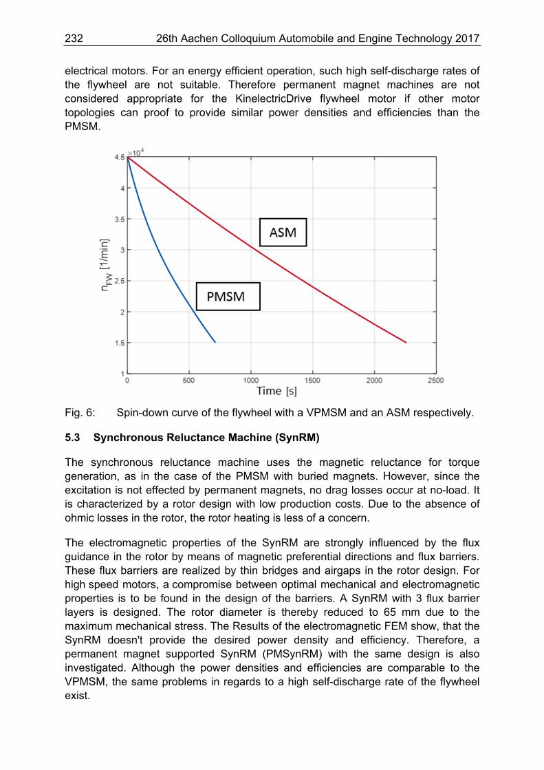
As the results of the 2D finite element simulations show, the PMSM achieved the highest efficiencies of up to 96.5 % in the base speed region. Since the magnetic field is produced by permanent magnets, the PMSM has high iron losses at high speed operation and no-load. This leads to lower efficiencies and a rapid self-discharge of the flywheel. The spin down curve of the flywheel at no-load operation is shown in Fig. 6. It considers the aerodynamic drag losses at 1 mbar, the bearing losses, losses of the rotational vacuum sealing and the no-load losses of the
232 26th Aachen Colloquium Automobile and Engine Technology 2017
electrical motors. For an energy efficient operation, such high self-discharge rates of the flywheel are not suitable. Therefore permanent magnet machines are not considered appropriate for the KinelectricDrive flywheel motor if other motor topologies can proof to provide similar power densities and efficiencies than the PMSM.
Fig. 6: Spin-down curve of the flywheel with a VPMSM and an ASM respectively.
5.3 Synchronous Reluctance Machine (SynRM)
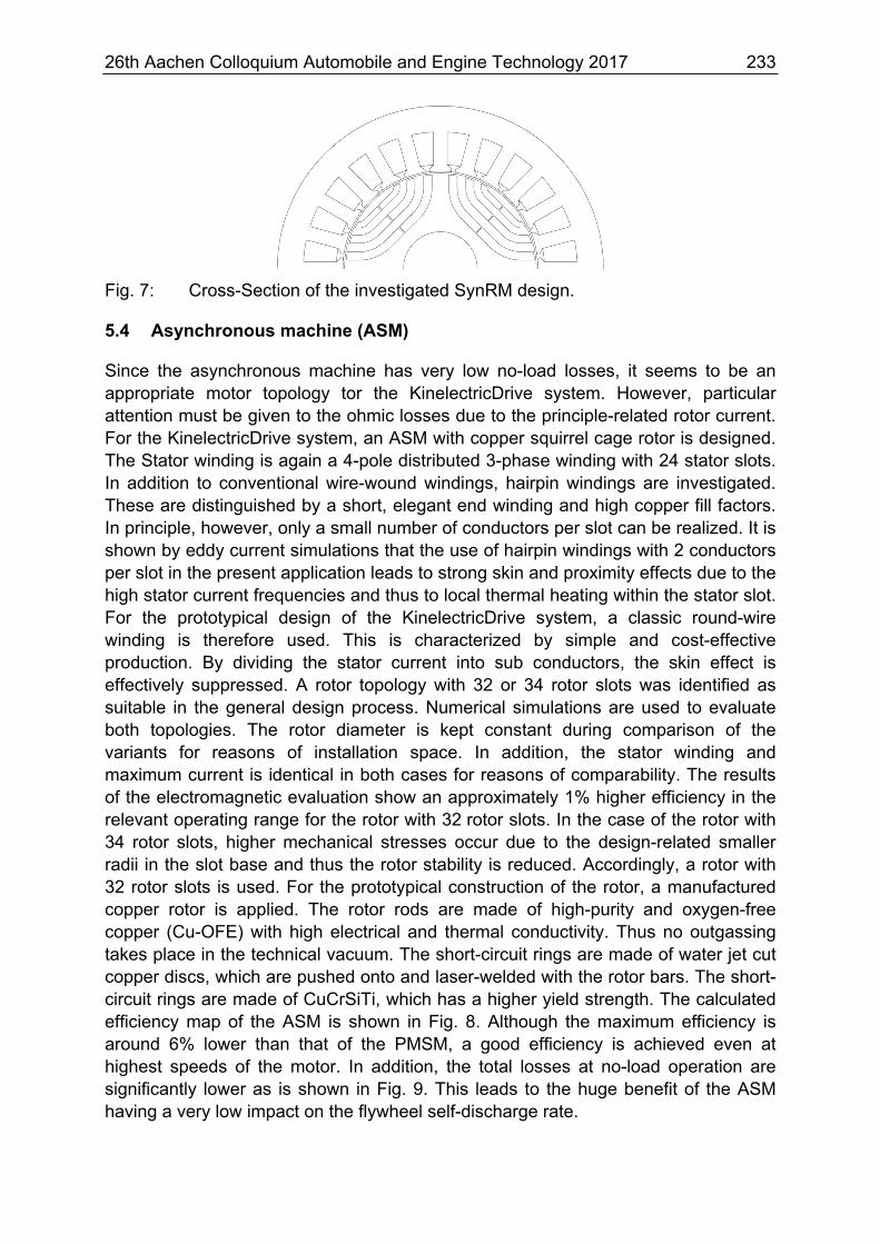
The synchronous reluctance machine uses the magnetic reluctance for torque generation, as in the case of the PMSM with buried magnets. However, since the excitation is not effected by permanent magnets, no drag losses occur at no-load. It is characterized by a rotor design with low production costs. Due to the absence of ohmic losses in the rotor, the rotor heating is less of a concern.
The electromagnetic properties of the SynRM are strongly influenced by the flux guidance in the rotor by means of magnetic preferential directions and flux barriers. These flux barriers are realized by thin bridges and airgaps in the rotor design. For high speed motors, a compromise between optimal mechanical and electromagnetic properties is to be found in the design of the barriers. A SynRM with 3 flux barrier layers is designed. The rotor diameter is thereby reduced to 65 mm due to the maximum mechanical stress. The Results of the electromagnetic FEM show, that the SynRM doesn't provide the desired power density and efficiency. Therefore, a permanent magnet supported SynRM (PMSynRM) with the same design is also investigated. Although the power densities and efficiencies are comparable to the VPMSM, the same problems in regards to a high self-discharge rate of the flywheel exist.
26th Aachen Colloquium Automobile and Engine Technology 2017 233
Fig. 7: Cross-Section of the investigated SynRM design.
5.4 Asynchronous machine (ASM)
Since the asynchronous machine has very low no-load losses, it seems to be an appropriate motor topology tor the KinelectricDrive system. However, particular attention must be given to the ohmic losses due to the principle-related rotor current. For the KinelectricDrive system, an ASM with copper squirrel cage rotor is designed. The Stator winding is again a 4-pole distributed 3-phase winding with 24 stator slots. In addition to conventional wire-wound windings, hairpin windings are investigated. These are distinguished by a short, elegant end winding and high copper fill factors. In principle, however, only a small number of conductors per slot can be realized. It is shown by eddy current simulations that the use of hairpin windings with 2 conductors per slot in the present application leads to strong skin and proximity effects due to the high stator current frequencies and thus to local thermal heating within the stator slot. For the prototypical design of the KinelectricDrive system, a classic round-wire winding is therefore used. This is characterized by simple and cost-effective production. By dividing the stator current into sub conductors, the skin effect is effectively suppressed. A rotor topology with 32 or 34 rotor slots was identified as suitable in the general design process. Numerical simulations are used to evaluate both topologies. The rotor diameter is kept constant during comparison of the variants for reasons of installation space. In addition, the stator winding and maximum current is identical in both cases for reasons of comparability. The results of the electromagnetic evaluation show an approximately 1% higher efficiency in the relevant operating range for the rotor with 32 rotor slots. In the case of the rotor with 34 rotor slots, higher mechanical stresses occur due to the design-related smaller radii in the slot base and thus the rotor stability is reduced. Accordingly, a rotor with 32 rotor slots is used. For the prototypical construction of the rotor, a manufactured copper rotor is applied. The rotor rods are made of high-purity and oxygen-free copper (Cu-OFE) with high electrical and thermal conductivity. Thus no outgassing takes place in the technical vacuum. The short-circuit rings are made of water jet cut copper discs, which are pushed onto and laser-welded with the rotor bars. The short-circuit rings are made of CuCrSiTi, which has a higher yield strength. The calculated efficiency map of the ASM is shown in Fig. 8. Although the maximum efficiency is around 6% lower than that of the PMSM, a good efficiency is achieved even at highest speeds of the motor. In addition, the total losses at no-load operation are significantly lower as is shown in Fig. 9. This leads to the huge benefit of the ASM having a very low impact on the flywheel self-discharge rate.

234 26th Aachen Colloquium Automobile and Engine Technology 2017
Fig. 8: Efficiency map of the ASM with 32 rotor slots.
Fig. 9: Map of total losses of the ASM with 32 rotor slots.
To ensure the thermal stability of the ASM, transient thermal simulations with the aid of a lumped parameter model are carried out. The loss profiles during a driving cycle are carried out by a drivetrain system model, taking the operating strategy of the flywheel motor into account. In Figure 10 the temperature profile of the motor during the third of three consecutive runs of a WLTP driving cycle is shown. As expected, the highest temperatures occur at the rotor surface, rotor endrings and the shaft. The Stator is well below its maximum allowed temperature. For the technical vacuum with down to 1 mbar, the ASM performs well. Based on the results, additional refinements of the operating strategy are possible to achieve a higher utilization of the flywheel motor.

26th Aachen Colloquium Automobile and Engine Technology 2017 235
Fig. 10: Temperature profile (third out of three consecutive WLTP cycles).
To ensure the mechanical firmness of the rotor, 3D stress simulations with linear plastic material properties are performed. Since the rotor is manufactured and not die-cast, relative movements between the rotor rods and the rotor slots can be expected. In the simulation, this is accounted for by the means of a frictional contact definition. Additionally, the H7/s6 shaft-hub connection is modeled with an effective penetration of 26 µm. A lock nut is installed to further fasten the rotor stack. It provides a total axial force of 22.4 kN. Results of the simulation are shown in Figure 11.
Fig. 11: Von Mises stress in MPa at rotor slot (left) and at cut view along the stack including squirrel cage and rotor stack (right).
6 Conclusion
In this paper, the design of a kinetic-electric powertrain and possible electric motor topologies for this system are discussed. Three concepts for the integration of the flywheel and the electric high speed motor are presented with their pros and cons. For a cost efficient design of the motor, a variant with a magnetic active rotor part made of higher-strength silicon-iron electrical steel in combination with a steel flywheel is chosen. The influence of the technical vacuum level on the motor design is discussed. For KinelectricDrive an operation at pressures between 1 mbar and 10 mbar is chosen. This is a good compromise between low aerodynamic drag
236 26th Aachen Colloquium Automobile and Engine Technology 2017
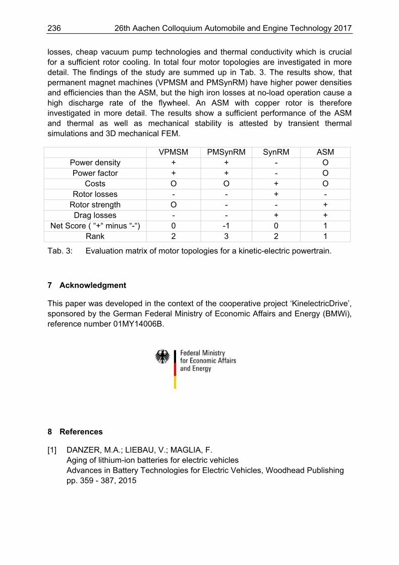
losses, cheap vacuum pump technologies and thermal conductivity which is crucial for a sufficient rotor cooling. In total four motor topologies are investigated in more detail. The findings of the study are summed up in Tab. 3. The results show, that permanent magnet machines (VPMSM and PMSynRM) have higher power densities and efficiencies than the ASM, but the high iron losses at no-load operation cause a high discharge rate of the flywheel. An ASM with copper rotor is therefore investigated in more detail. The results show a sufficient performance of the ASM and thermal as well as mechanical stability is attested by transient thermal simulations and 3D mechanical FEM.
VPMSM PMSynRM SynRM ASM Power density + + - O Power factor + + - O
Costs O O + O Rotor losses - - + -
Rotor strength O - - + Drag losses - - + +
Net Score ( “+“ minus “-“) 0 -1 0 1 Rank 2 3 2 1
Tab. 3: Evaluation matrix of motor topologies for a kinetic-electric powertrain.
7 Acknowledgment
This paper was developed in the context of the cooperative project ‘KinelectricDrive’, sponsored by the German Federal Ministry of Economic Affairs and Energy (BMWi), reference number 01MY14006B.
8 References
[1] DANZER, M.A.; LIEBAU, V.; MAGLIA, F. Aging of lithium-ion batteries for electric vehicles Advances in Battery Technologies for Electric Vehicles, Woodhead Publishing pp. 359 - 387, 2015
26th Aachen Colloquium Automobile and Engine Technology 2017 237
[2] GERMAN ENVIRONMENT AGENCY National Inventory Report for the German Greenhouse Gas Inventory 1990 – 2015 UNFCCC Submission 2017
[3] BUCHROITHNER, A.; BADER, M. History and development trends of flywheel-powered vehicles as part of a systematic concept analysis EEVC Brussels 2011
[4] MÜLLNER, F.; NEUDORFER, H.; RECHEIS, M. highFly – Entwicklung eines Flywheels als elektrischer Energiespeicher für den mobilen Einsatz Elektrotech. Inftech, vol. 132, no. 1 pp. 87–94, 2015
[5] http://www.gkn.com/en/newsroom/news-releases/group/2014/gkn-and-the-go-ahead-group-using-f1-technology-to-improve-fuel-efficiency-of-london-buses/ (accessed on 12.07.2017)
[6] WEGLEITER, H. Flywheel als Energiespeicher in Hybrid und Elektrofahrzeugen für den Individualverkehr Blue Globe Report – Klima- und Energiefonds, 2013
[7] HEDLUND, M.; LUNDIN, J.; DE SANTIAGO, J.; ABRAHAMSSON, J.; BERNHOFF, H. Flywheel Energy Storage for Automotive Applications Energies 2015, 8, pp. 10636-10663, 2015

238 26th Aachen Colloquium Automobile and Engine Technology 2017