analysis and optimisation of the tuning of the twelfths for a clarinet...
TRANSCRIPT

Analysis and optimisation of the tuning ofthe twelfths for a clarinet resonator
V. Debut a,*, J. Kergomard a, F. Laloe b
a Laboratoire de Mecanique et d!Acoustique-CNRS UPR 7051, 31 chemin Joseph Aiguier,13402 Marseille cedex 20, France
b Laboratoire Kastler-Brossel, Dept de physique de l!ENS UMR CNRS 8552, 24 rue Lhomond,75231 Paris cedex 05, France
Received 1 June 2003; received in revised form 1 May 2004; accepted 1 August 2004
Abstract
Even if the tuning between the first and second register of a clarinet has been optimized byinstrument makers, the lowest twelfths remain slightly too large (inharmonicity). In this arti-cle, we study the problem from two di!erent points of view. First, we systematically reviewvarious physical reasons why this inharmonicity may take place, and the e!ect of di!erent boreperturbations inserted in cylindrical instruments such as bore flare, open and closed holes,taper, temperature gradients, visco-thermal e!ects, etc. Applications to a real clarinet resona-tor and comparisons with impedance measurements are then presented. A commonly acceptedidea is that the register hole is the dominant cause for this inharmonicity: it is natural to expectthat opening this hole will shift the position of the resonances of the instrument to higher fre-quencies, except of course for the note for which the hole is exactly at the pressure node. Weshow that the real situation is actually more complicated because other e!ects, such as openholes or bore taper and bell, introduce resonance shifts that are comparable but with oppositesign, so that a relatively good overall compensation takes place. This is checked by experimen-tal and theoretical studies of the acoustical impedance curves of a clarinet. The origin of theobserved inharmonicity in playing frequencies is therefore di!erent, maybe related to the reedor the vocal tract. In a second part, we use an elementary model of the clarinet in order toisolate the e!ect of the register hole: a perfect cylindrical tube without closed holes.
0003-682X/$ - see front matter ! 2004 Elsevier Ltd. All rights reserved.doi:10.1016/j.apacoust.2004.08.003
* Corresponding author. Tel.: +33 491 16 40 90; fax: +33 491 16 40 12.E-mail address: [email protected] (V. Debut).
Applied Acoustics 66 (2005) 365–409
www.elsevier.com/locate/apacoust

Optimization techniques are then used to calculate an optimum location for the register hole(without taking into account the use of the register hole as a B flat tone hole); the result turnsout to be close to the location chosen by clarinet makers. Finally, attempts are made numer-ically to improve the situation by introducing small perturbations in the higher part of thecylindrical resonator, but no satisfactory improvement is obtained.! 2004 Elsevier Ltd. All rights reserved.
Keywords: Clarinet; Inter-register inharmonicity; Register hole; Length corrections
1. Introduction
Many contributions, either experimental or theoretical, have been made in thepast to improve our understanding of single reed woodwind instruments (see e.g.[1–4]). Our knowledge of the linear behaviour of the resonator is now satisfactory,which probably explains why most of the recent literature deals with the understand-ing of the sound production and oscillation regimes, an inherently non-linear prob-lem. This does not mean that all interesting questions concerning the linearbehaviour of the resonator have been solved. For instance, Benade [5] proposed inthe seventies some basic ideas and methods allowing the qualities of a wind instru-ment to be characterised (impedance peak alignment), but more detailed explora-tions along this line would be useful; Meynial and Kergomard [6] proposedrelatively recently simple acoustical systems that shift the scale of a woodwind bya given micro-interval. Concerning the relation between linear properties and non-linear oscillations, Dalmont et al. [7] discusses in general how it is possible to predictthe emission frequencies, and even some aspects of the clean intonation and tone col-our, which naturally leads to the design of modified instruments as soon as appro-priate optimization criteria are defined. Recently, optimization techniques havebeen used in order to define longitudinal profiles of brass instruments [8].
An example of an unsolved problem is given by the clarinet. While many musi-cians agree that it is now a well tuned instrument, the twelfths corresponding tothe four lowest tones remain slightly too large, by 20 or 30 cents [9–11]. One couldimagine many reasons for this problem: deviation of the bore from purely cylindricalshape, existence of open or closed side holes (cavities), temperature gradient, etc. Agenerally accepted idea states nevertheless that the main reason resides in the registerhole, because it cannot be ideally placed for every fingering.
The first purpose of the present article is to analyze the origin of this tuning prob-lem in detail. We will actually see that the occurrence of wide twelfths at either end ofthe clarinet register is not an obvious problem in terms of linear impedance theory, incontradiction with common wisdom. In real clarinets, various e!ects of oppositesigns tend to compensate each other, at least partially (role of the flaring bell for in-stance). The second purpose of the article is to investigate whether or not it is pos-sible to design a register hole allowing the first two complete registers to be perfectlywell tuned (the definition of the registers will be given in the next section), ignoring
366 V. Debut et al. / Applied Acoustics 66 (2005) 365–409

all the other sources for inharmonicity except the register hole. We will then reasonon a simplified shape, cylindrical and without tone holes, the di!erent values of thetones being adjusted simply by choosing di!erent lengths for the tube. Two questionswill be discussed:
(i) what is the optimum location of the register hole for the tuning of the twelfthsintervals between the first two registers?
(ii) is it possible to propose some simple system, located upstream from the highesttone hole, to provide a good correction to the residual tuning defaults?
The outline of this paper is as follows: the second section recalls some general fea-tures of the clarinet. The third section is devoted to the first study: it analyzes thelength corrections and their variation with frequency for the main kinds of discon-tinuities encountered in wind instruments. It ends with an application to a real clar-inet resonator in order to find whether the register hole is the main culprit of theclarinet tuning defect; calculations are compared with measurements. A validationof the calculations to first order in the ratio of the length correction to the wave-length is also given as well as a complete analysis of the e!ects of an open and closedtone holes. Then, Sections 4 and 5 are concerned with the second part of our studyand answer questions (i) and (ii), respectively. Some useful formulae are given inAppendix A.
2. Generalities on the clarinet
2.1. Definitions
For a given fingering, several resonance frequencies of the resonator occur, andseveral oscillation regimes can be obtained. The term register is used to describethe set of tones obtained for the same regime: the first register involves the tones cor-responding to the first mode (i.e. the first resonance frequency) of the resonator, thefrequencies being denoted f1, and the second register involves the tones correspond-ing to the second mode, the frequencies being denoted f2 (where f2 is approximately3f1). The opening of the register hole allows the musician to ‘‘jump’’ from a giventone of the first register to the corresponding tone of the second register, one octaveand a fifth above, the first two registers covering ideally more than 3 octaves. Wenotice that while this division into two registers seems obvious to the scientist, theanalysis of the characteristics of the tone colour is not so clear, and musicians dividethis musical compass in four registers: chalumeau, throat, clarinet and extreme [12].For the fingerings corresponding to the higher tones of the first register, i.e. for writ-ten fingerings from f 0# to a 0#, 1 the opening of the register hole is not su"cient inorder to get the proper twelfth, and it is necessary to modify slightly the fingering
1 The notation system adopted in this paper is the same as that used by Baines [13].
V. Debut et al. / Applied Acoustics 66 (2005) 365–409 367

in order to ensure the good tuning. Thus, in order to play the corresponding twelfths(i.e. tones from c000#), the third resonance, corresponding to an interval of a 17th, isused, corresponding to that the physicist can call the third register (see Fig. 1).
The most commonly used clarinet is the B-flat clarinet which sounds one tone be-low the written note. Five parts can be distinguished on a clarinet: the mouthpiece,the barrel, the upper and lower joints and the bell. To first approximation, the clar-inet is a cylindrical instrument, but a detailed determination of the geometricaldimensions of the instrument reveals deviations from this regular, cylindrical shapeover parts which are short with respect to the wavelength. This is shown in Fig. 2with a bore plot of a Bu!et Crampon clarinet, system Boehm, no F53682 (see Table1 for bore and holes measurements) which will be the central clarinet in the investi-gations. Moreover, the existence of tone and register holes, bore irregularities, ther-
chalumeau throat clarinet
b’
b’’’’
mode 2
mode 1
mode 3
e
c’’’
c’’’#
a’#f ’#
extreme
Fig. 1. Compass and operative resonance frequency for a clarinet (written notes).
0 100 200 300 400 500 6000
5
10
15
20
25
30
35
distance (mm)
radi
us (m
m)
Fig. 2. Radius of a clarinet as a function of the distance from the reed tip (see Table 1).
368 V. Debut et al. / Applied Acoustics 66 (2005) 365–409

mal gradient and dispersion due to visco-thermal e!ects alter the resonance frequen-cies and their harmonicity; they must be included for a detailed study of the tuning ofthe instrument.
Table 1Numerical data concerning the Bu!et Crampon clarinet investigated
No. ‘ (mm) r (mm) h (mm)
24 152.7 1.4 13.023 166.9 2.35 7.122 193.4 2.8 7.121 202.9 2.7 7.120 213.2 2.55 7.219 230.4 2.4 6.418 238.9 3.9 10.817 241.3 2.35 6.816 252.2 2.45 8.815 270.5 2.3 6.914 284.3 3.3 8.813 287.1 2.7 6.812 289.3 2.85 6.911 308.2 3.95 7.410 318.8 2.4 7.29 348.9 3.55 6.58 364.8 4.05 8.97 369.5 3.95 6.16 391.0 3.85 8.95 413.1 4.85 8.94 445.6 5.4 6.03 472.9 6.1 5.02 504.9 5.6 5.21 543.7 5.8 4.4
Position (mm) Diameter (mm)
0 041 13.774 14.589 14.989 14.8117.5 14.6117.5 15.6152.5 14.5492.5 14.5526 15.1565 16.9578.2 18.4598 22.2664 60
Tones holes are numbered from 1 to 24 in order of decreasing distance from mouthpiece, the 24th beingthe register hole. Distances are given from the reed tip. For the input impedance measurements themouthpiece is replaced by a cylindrical tube of length 77 mm. For the comparison with computations, aposition correction of about !12 mm is introduced for the tone hole locations.
V. Debut et al. / Applied Acoustics 66 (2005) 365–409 369

2.2. Inharmonicity and sound production
The sound of the clarinet is produced by self-sustained oscillations. Theory shows[14] that, at low sound intensity, the playing frequencies are determined by the zeroof the imaginary part of the input admittance of the resonator (they are thereforevery close to the frequencies of the maxima of the input impedance modulus). Inaddition, the reed has also a small influence on the playing frequency, for two di!er-ent reasons: the volume velocity created by the motion of the reed movement, whichadds to that produced by the pressure di!erence across the reed opening; the fre-quency pulling e!ect of the resonance of the reed (at higher frequencies) combinedwith its damping. It can be shown that these two e!ects can be taken into accountby introducing appropriate length corrections to the instrument, which are almostindependent of the frequency [1,7]. At higher sound intensities, the playing frequencyalso depends on other impedance peaks; it can slightly change under the e!ect of theinharmonicity of the resonances of the resonator. A proper harmonicity of the firsttwo resonances is therefore important for the pitch of a tone: the sound frequencyremains independent of the playing level, even if the first two resonances have similarmagnitude, and good impedance peak cooperation ensures a stable sound emission[15]. This question is actually intricate because it involves the influence of manyparameters. Here, for the sake of simplicity we limit ourselves to low intensitysounds; in other words, our goal will just be to achieve a perfect tuning at leastfor pianissimo levels.
In this article, we will distinguish between inter-resonance inharmonicity and inter-register inharmonicity. The former refers to the inharmonicity between the first tworesonance frequencies of the resonator for a given fingering; the latter defines the ra-tio between the resonance frequencies of the first impedance peak when the registerhole is closed and the second one when the register hole is open. 2
2.3. Method and approximation
The shape of a clarinet is very close to a pure cylinder. For a given fingering of thechalumeau, with first resonance frequency f1 an e!ective length ‘e! can be defined as
‘eff " c=4f 1;
where c is the speed of sound. A first approximation of this length is given by thephysical length between the input of the instrument (taking into account a lengthcorrection for the above mentioned reed e!ects) and the first open tone hole position,where the tube is assumed to be cut. All the perturbations from the cylindrical shape,such as enlargements or contractions, closed tone holes, as well as the precise e!ects
2 The targeted interval is a pure twelfth, i.e. almost a ratio of 3. Actually for a tempered scale, the ratiois slightly di!erent, because the tempered intervals are di!erent from the natural ones: the exact value is219/12 = 2.9966. The relative di!erence is 0.11%, i.e. 2 cents (it is the di!erence between the tempered fifthand the harmonic one, called the ‘‘skhisma’’). Nevertheless this di!erence is very small and for simplicity inwhat follows we will ignore it (2 cents are almost inaudible, and within the ‘‘tunability range’’ [16,17]).
370 V. Debut et al. / Applied Acoustics 66 (2005) 365–409

of the open tone hole (depending on the downstream geometry and radiation prop-erty), can be regarded as small corrections to this first approximation leading to thecorrect value, ‘e!. For the lowest tone, for which all holes are closed, an equivalentlength of the flaring horn is used as in [1]. If the resonator was purely cylindrical andlossless, the second resonance frequency would be exactly f2 = 3f1 However all theperturbations produce corrections slightly di!erent from those on the first resonance:this creates the inter-resonance inharmonicity (for inter-register inharmonicity, theopening of the register hole also needs to be taken into account). Here, we are actu-ally concerned not by the e!ect itself of the perturbations from the cylindrical shape,but by the variation of this e!ect between the two registers.
The concept of frequency dependent length corrections is an adequate tool for thisstudy. As in [6] the corrections upstream of the first open hole can be calculated sep-arately for each kind of perturbation, with respect to the e!ective input of the tube(taking into account the reed e!ects) where the imaginary part of the admittancemust be zero for self-sustained oscillations. The frequency dependence of the lengthcorrections for all fingerings provides the inharmonicity. Only the e!ect of the partthat is upstream the first open hole needs to be studied for each fingering.
All calculations are carried out by ignoring the di!erent kinds of dissipation (dueto visco-thermal e!ects in the boundary layers, to radiation, etc.): weak dissipation isknown to have a negligible e!ect on the resonance frequencies [18]. In Appendix Bthe e!ect of the resistance of a small hole is discussed: it is shown that nonlineare!ects can modify the playing frequency at high sound intensity as it is observedby Dalmont et al. [35]; in this study, only low sound intensity is considered. A con-sequence is the systematic use of purely imaginary impedances, which means for theresonance condition, that the input impedance is infinite. Perturbation to the planarmode theory is classically taken into account using lumped elements representing thee!ects of higher order, evanescent modes of the tubes.
3. Length correction and inharmonicity produced by a small perturbation: analysis ofthe di!erent e!ects for a real clarinet resonator
In this section, we study the analytic expressions of length corrections and inhar-monicity of the first two resonance frequencies associated with small perturbationsto a purely cylindrical shape. This formulation gives a good idea of the inharmonic-ity encountered on a real clarinet resonator.
3.1. Length corrections: definition
The e!ect of a geometrical perturbation on a cylindrical resonator may be ex-pressed conveniently in terms of a length correction to the main tube, denoted D‘.Using an exact formulation of D‘ is possible but in this study, we use an approxima-tion of length corrections to first order in the ratio of the length correction to thewavelength: this gives a su"ciently accurate determination of the resonance frequen-cies. Moreover, the length corrections associated with di!erent perturbations can be
V. Debut et al. / Applied Acoustics 66 (2005) 365–409 371

simply added as we will see in a particular example. The perturbation is located at adistance ‘ from the e!ective input, which is the origin of the coordinates once theclarinet embouchure has been replaced by an equivalent cylinder and the reed e!ectshave been taken into account (see Section 3.5.1).
3.2. Inharmonicity of the resonance frequencies
Inharmonicity can be defined as the relative di!erence between the resonance fre-quency fn and n times the first resonance f1, as follows:
IH " fn ! nf 1
nf 1
" ‘eff # D‘1‘eff # D‘n
! 1 " !D‘n ! D‘1‘eff
# oD‘‘eff
! "; $1%
where ‘e! is the acoustic length of the unperturbed system and D‘n is the length cor-rection associated to the nth resonance.
In the case IH > 0 the basic intervals are enlarged; when IH < 0 the intervals arereduced. In the present paper, results are given in cent; the cent is the micro-intervalequal to one hundredth of a tempered semi-tone:
1 cent " 5:78& 10!4 and IHcents "IH
5:78& 10!4:
We notice that the smallest frequency deviation perceptible by the human ear, esti-mated to be 4 cents, corresponds to IH . 0.25%.
3.3. Length corrections and inharmonicity formulae for acoustic basic systems
This section contains analysis of inharmonicity associated with the simple acous-tical systems usually encountered in a clarinet, and depicted in Table 2. This sectionuses results obtained by Meynial and Kergomard [6] concerning the e!ects of theinsertion of an admittance branched in parallel and an impedance branched in series,on a cylindrical tube. From the calculation of first order length corrections, 3 analyt-ical expressions of inharmonicity between the first and second resonance frequenciesare derived. For exact formulations of length corrections, the reader is referred toAppendix A.
3.3.1. General formulation for an admittance in parallel and an impedance in seriesBefore a detailed investigation of di!erent cases of discontinuities, we present two
general formulations for any discontinuity inserted in parallel or in series branchedon a straight cylindrical tube.
For the case of a discontinuity inserted in parallel, we denote Y the admittance ofthe discontinuity 4 and Yup and Ydown the main tube admittances upstream and
3 The expression first order length corrections refers to length corrections expanded to first order in theratio of the length correction to the wavelength.
4 Throughout the paper the admittance is defined as a ratio of an acoustic volume velocity to anacoustic pressure.
372 V. Debut et al. / Applied Acoustics 66 (2005) 365–409

Table 2Acoustic basic systems and associated length corrections
Register hole
Tone hole
Closed-hole
Abrupt change in cross section inthe upper part of the instrument
Localized enlargement/contraction in the upper partof the instrument
Truncated cone in the upper partof the instrument
V. Debut et al. / Applied Acoustics 66 (2005) 365–409 373

downstream the discontinuity, respectively. The following equation can be written atthe location of the discontinuity (x = ‘),
Y up " Y # Y down: $2%
Looking backwards to the top-end of the resonator where the input impedance mustbe infinite for self-sustained oscillations (i.e. from x = ‘ to x = 0), and writingYdown = !jYc tan k(‘ + D‘), we get from Eq. (2):
!jY c tan k‘ " Y ! jY c tan k$‘# D‘%; $3%
where D‘ is the length correction, Yc = S/qc is the characteristic admittance of themain tube (q is the density of air and S the cross section area of the main tube),k = 2pf/c is the wavenumber and j "
#######!1
p. After some algebra, the following result
is obtained:
kD‘ " Arctan!j Y
Y ccos2k‘
1! 12j YY c
sin 2k‘
!
; $4%
which can be approximated in the limit of small Y/Yc by
kD‘ ’ !jYY c
cos2k‘: $5%
For the case of a series impedance Z branched on a cylindrical tube, similarexpressions are found to be, respectively:
kD‘ " Arctan!j Z
Zcsin2k‘
1# 12j ZZc
sin 2k‘
!
; $6%
and in the limit of small Z/Zc,
kD‘ ’ !jZZc
sin2k‘: $7%
Formulae (5) and (7) can also be deduced from Rayleigh!s variational principle [19].They are useful for di!erent kinds of small discontinuities (see [6]), but for some par-ticular cases, other formulae need to be derived as we see below.
3.3.2. Insertion of a side holeStarting from the tone hole model proposed by Keefe [20] with the values given by
Dubos et al. in [21], we propose a new calculation of an equivalent length that in-cludes the e!ects of both the series and shunt impedances. Consequences for thecases of a register hole, an open side hole and a closed hole are subsequentlydiscussed.
3.3.2.1. Side hole. Referring to [21] for the tone hole model, the acoustic pressure andthe acoustic volume velocity at both sides of the hole can be related by the followingtransfer matrix:
374 V. Debut et al. / Applied Acoustics 66 (2005) 365–409
A B
C D
! "" 1
1! Y sZa=4
1# Y sZa=4 Za
Y s 1# Y sZa=4
! "; $8%
where Za and Ys are the series impedance and shunt admittance, respectively. Thisformulation emphasizes the dual role of the two terms Za and Ys, as opposed to for-mulations based on the classical T or P equivalent circuits. Manipulation of Eq. (8)gives the length correction:
!jY c tan k$‘# D‘% " !Y s # DY ‘
A! ZaY ‘; $9%
where Y‘ = !jYc tan k‘. Finally:
kD‘ " Arctan!jY s=Y ccos
2k‘! jZa=Zcsin2k‘
1# Y sZa=4# j$Za=Zc ! Y s=Y c% sin k‘ cos k‘
! ": $10%
As a result, Eq. (10) is a general expression for the length correction of a tubebranched to a cylindrical tube. It gives the influence of both the series and shuntimpedances in the determination of the equivalent length. No assumption has beenmade concerning the dimensions and shape of the hole: it is therefore possible to de-rive first order approximations for special cases as tone hole, register hole or closedhole from the relative influence of Za and Ys. For instance, in the case of an openhole, both Za and Ys are inductive. With the low frequencies approximation, Eq.(10) shows that D‘ is mostly determined by the shunt admittance. If Ys/Yc ' 1,the length correction is small and Eq. (10) gives Eq. (5); this is the case of the registerhole.
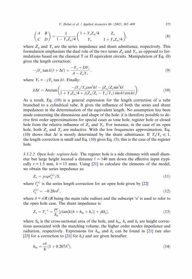
3.3.2.2. Open hole: register hole. The register hole is a side chimney with small diam-eter but large height located a distance ‘. 140 mm down the e!ective input (typi-cally r = 1.5 mm, h = 13 mm). Using [21] to calculate the elements of the model,we obtain the series impedance as:
Za " jxq‘$o%a =S; $11%
where ‘$o%a is the series length correction for an open hole given by [22]
‘$o%a " !0:28rd3; $12%
where d = r/R (R being the main tube radius) and the subscript "o! is used to refer tothe open hole case. The shunt impedance is:
Zs " Y !1s " qc
Sh
(j tan(k$h# hm # hr%) # jkhs); $13%
where Sh is the cross-sectional area of the hole, and hm, hs and hr are height correc-tions associated with the matching volume, the higher order modes impedance andradiation, respectively. Expressions for hm and hs can be found in [21] (see also[23] for a correction to [21] for hs) and are given hereafter:
hm " rd8$1# 0:207d3%; $14%
V. Debut et al. / Applied Acoustics 66 (2005) 365–409 375

hs " r$0:82! 0:193d! 1:09d2 # 1:27d3 ! 0:71d4%: $15%
Since the situation at the end of a hole is not very well defined (due to the presenceof a key above the hole and/or undercutting), a radiation length correction hr be-tween the flanged and unflanged cases is considered, assumed to be
hr " 0:7r: $16%
In the low frequency limit, the shunt impedance is well approximated by
Zs " jqcSh
kh0; $17%
where
h0 " h# hm # hs # hr: $18%
This equation allows us to discuss the relative influence of the series and shuntimpedances. Calculation gives jYsZaj . 0.0045% which confirms that the seriesimpedance can be ignored in the case of a long chimney with a small diameter. Fi-nally, Eq. (10) is identical to (5), which provides:
kD‘ ’ ! Sh‘
Sh0cos2k‘k‘
; $19%
where ‘ is the distance of the hole from the e!ective input. Eq. (19) shows that asmall open side hole always introduces a negative length correction, i.e. an increasein the resonance frequencies. It also shows that D‘ decreases as the inverse of thesquare of frequency. Therefore, the register hole opening a!ects the first resonancefrequencies much more than the second one, which is an important requirementfor the clarinet to overblow correctly [24].
From Eq. (19), since the register hole has no e!ect on tones of the first register forwhich it is closed, the frequency shift of the second resonance frequency due to theregister hole opening can be derived. We then get:
IH ’ !D‘2‘eff
’ 2
3pSh
Sh0cos2k2‘
k2; $20%
where k2 = 3k1, k1 being the wavenumber of the fundamental frequency of the playedtone. This expression shows that the register hole opening generates positive inhar-monicity by pulling the second vibration mode upward in frequency at both ends ofthe register scale and has no e!ect at a pressure node as it is well known (see Fig. 3where r = 1.4 mm, h = 13 mm and ‘ = 140 mm). It also appears that the two geomet-rical parameters which control inter-resonance inharmonicity are Sh 0/Sh and ‘.
3.3.2.3. Open hole: tone hole. In the limit of zero frequency, the shunt admittance ofan open hole increases to infinity (see Eq. (5)) and the main tube behaves as if it wascut at the location of the hole. The ratio Ys/Yc becomes large for tone holes and Eq.(10) can no longer be used since the perturbation cannot be considered as small any-more. As a consequence, D‘ is no longer seen as an extension of the entire air columnof length ‘e! but as an additional length to ‘ the distance from the e!ective input to
376 V. Debut et al. / Applied Acoustics 66 (2005) 365–409

the hole location. For an open hole of height h 0 (see Eq. (18)), radius r at distance ‘dfrom the open end, the length correction is now obtained from:
!jY c cot kD‘ "Y s # DY ‘
A# ZaY ‘; $21%
where now Y‘ = !jYc cot k‘d. Thus:
kD‘ " Arctan!jY c($1# ZaY s=4% ! jZaY c cot k‘d)
Y s ! $1# ZaY s=4%jY c cot k‘d
! ": $22%
For a real clarinet using the expressions for Za, Ys and Yc for an open hole, we seethat the quantity jZaYs/4j is small compared to unity, except for the four bottomtones for which the order of magnitude is to 0.015. In the same way, the term inbracket at the numerator is close to unity. This leads us to assume that Za has a neg-ligible e!ect in this study for open holes especially since we focus on inharmonicity.Setting the term in bracket to unity in Eq. (22) and using Taylor!s formula to thethird order in k‘d and to the first order in kD‘, the tone hole equivalent lengthbecomes:
D‘ ’ 11
‘hole# 1
‘d$1#$k‘d%2=3%
; $23%
where ‘hole = h 0S/Sh is a transformed hole length [1] relative to the geometry of thetone hole. From Eq. (23), the length correction becomes a constant value in the lower
e f g a b c’ d’ e’ f’ g’ a’0
5
10
15
20
25
30
35
40
45
50
Fingering
Freq
uenc
y de
viat
ion
(cen
ts)
Fig. 3. Shift of the second resonance frequency due to a register hole of radius r = 1.4 mm, height h = 13mm, located a distance ‘ = 140 mm from the e!ective input. For the b flat fingering, the register hole doesnot alter the second vibration mode since, in this case, the register hole is located at one third the e!ectivelength.
V. Debut et al. / Applied Acoustics 66 (2005) 365–409 377
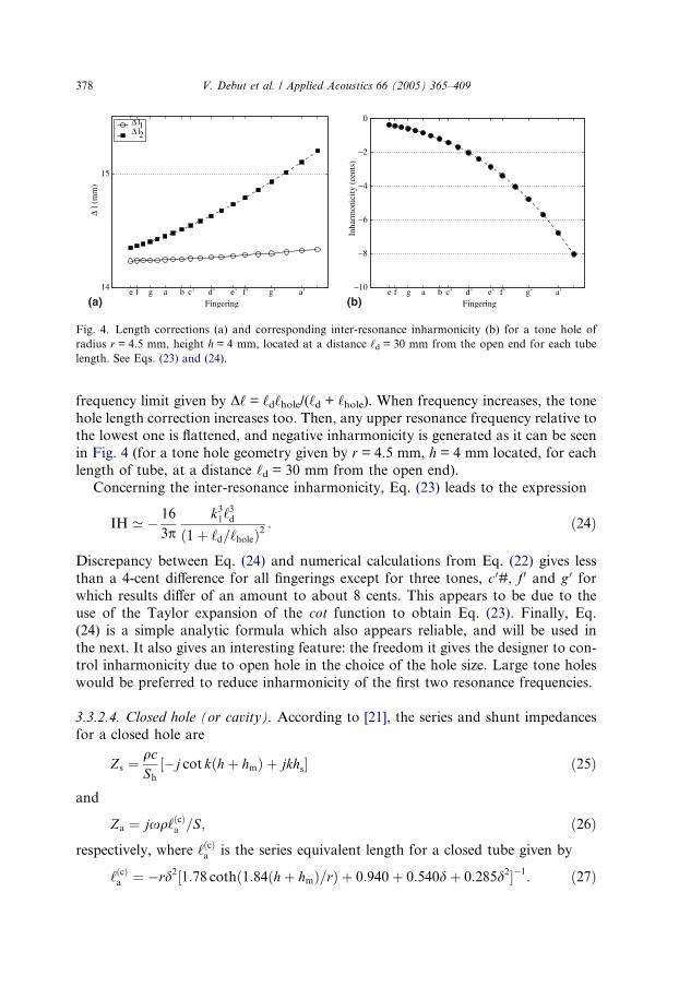
frequency limit given by D‘ = ‘d‘hole/(‘d + ‘hole). When frequency increases, the tonehole length correction increases too. Then, any upper resonance frequency relative tothe lowest one is flattened, and negative inharmonicity is generated as it can be seenin Fig. 4 (for a tone hole geometry given by r = 4.5 mm, h = 4 mm located, for eachlength of tube, at a distance ‘d = 30 mm from the open end).
Concerning the inter-resonance inharmonicity, Eq. (23) leads to the expression
IH ’ ! 16
3pk31‘
3d
$1# ‘d=‘hole%2: $24%
Discrepancy between Eq. (24) and numerical calculations from Eq. (22) gives lessthan a 4-cent di!erence for all fingerings except for three tones, c 0#, f 0 and g 0 forwhich results di!er of an amount to about 8 cents. This appears to be due to theuse of the Taylor expansion of the cot function to obtain Eq. (23). Finally, Eq.(24) is a simple analytic formula which also appears reliable, and will be used inthe next. It also gives an interesting feature: the freedom it gives the designer to con-trol inharmonicity due to open hole in the choice of the hole size. Large tone holeswould be preferred to reduce inharmonicity of the first two resonance frequencies.
3.3.2.4. Closed hole (or cavity). According to [21], the series and shunt impedancesfor a closed hole are
Zs "qcSh
(!j cot k$h# hm% # jkhs) $25%
and
Za " jxq‘$c%a =S; $26%
respectively, where ‘$c%a is the series equivalent length for a closed tube given by
‘$c%a " !rd2(1:78 coth$1:84$h# hm%=r% # 0:940# 0:540d# 0:285d2)!1: $27%
e f g a b c’ d’ e’ f’ g’ a’14
15
Fingering
! l (
mm
)
! l1! l2
e f g a b c’ d’ e’ f’ g’ a’"10
"8
"6
"4
"2
0
Fingering
Inha
rmon
icity
(cen
ts)
(a) (b)
Fig. 4. Length corrections (a) and corresponding inter-resonance inharmonicity (b) for a tone hole ofradius r = 4.5 mm, height h = 4 mm, located at a distance ‘d = 30 mm from the open end for each tubelength. See Eqs. (23) and (24).
378 V. Debut et al. / Applied Acoustics 66 (2005) 365–409

In the low frequency approximation, the shunt impedance becomes
Zs "qcSh
!jk$h# hm%
;
and shows that it behaves as a shunt acoustic compliance C = v/qc2 determined by itsvolume v = Sh(h + hm). Substituting Za and Zs in Eq. (10) and denoting X = v/S‘, thelength correction to first order is found to be:
D‘ ’ X ‘cos2k‘# ‘$c%a sin2k‘; $28%
which can be rewritten in
D‘ ’ $X ‘! ‘$c%a %cos2k‘# ‘$c%a : $29%
This expression shows that the e!ect of a closed hole inserted on a cylindrical tubedepends mainly on its size and position. It also shows that the change in inertancedescribed by ‘$c%a appears in the determination of the series closed-hole length correc-tion. For the lowest tone of a clarinet, when adding each hole contribution, it gives a6 mm length decrease on the closed-hole length correction for this fingering, i.e., a20-cent raising e!ect for the pitch of the written tone e. This term must be taken intoaccount especially when investigating the tuning of a real instrument for which manycavities can act for a given fingering; this cannot be neglected as it is done in severalpapers [6,25]. We notice that since k‘' 1, the e!ect of a cavity is proportional to theratio of the inserted volume to the volume of air included between the reed tip andthe closed hole. With the use of Eq. (29), inter-resonance inharmonicity becomes:
D‘1 ! D‘2 " ! vS! ‘$c%a
$ %$cos23k1‘! cos2k1‘%;
" 2vS! ‘$c%a
$ %sin22k1‘ cos 2k1‘;
so that:
IH ’ 4
pvS! ‘$c%a
$ %k1sin
22k1‘ cos 2k1‘: $30%
The result depends on two geometrical parameters, the location ‘ and the ratio v/Swhere v is the hole volume. Dealing with the case of real clarinet resonator and ignor-ing the e!ect of Za in Eq. (10) underestimates the cavity e!ect to about 10 cents forthe lowest fingerings when adding each cavity contribution. This confirms the neces-sity to take into account the series impedance Za in the length correction calcula-tions. Besides, as a consequence of the term cos 2k1‘, either negative or positiveinharmonicity is associated with a closed hole (see Fig. 5 for a hole volume equalto v = 0.3 cm3). Finally, since the magnitude is proportional to the wavenumberk1, inharmonicity associated with a hole of fixed size and position increases withthe fundamental frequency of the played tone.
3.3.3. Localized enlargement/contractionConsider a localized enlargement (or contraction) of length ‘ 0 located at distance ‘
from the e!ective input in a cylindrical air column and let a = S 0/S be the ratio of the
V. Debut et al. / Applied Acoustics 66 (2005) 365–409 379

cross section area of the enlargement (or contraction) to the one of the main tube.Assuming a to be close to the unity (only small bore changes are considered), we ob-tain the change in resonance frequencies expressed through length correction accord-ing to (see Appendix A, Eq. (A.2)):
kD‘ " $a! 1% sin k‘0 cos k$2‘# ‘0%: $31%
Then, the relationship between first and second resonance frequencies is:
IH ’ 4
3p$a! 1%$sin32k1$‘# ‘0% ! sin32k1‘%; $32%
which states that the two diameter discontinuities located at points ‘ and ‘ + ‘ 0 createeither positive or negative inharmonicity. This is shown in Fig. 6 in the case of anenlargement (a = 1.04) of length ‘ 0 = 10 mm.
Substituting ‘ = 0 in Eqs. (31) and (32), the e!ects due to a change in cross sectionin part of a cylindrical tube are calculated. The length correction becomes
# /4 # /2" 0.5
0
0.5
kl
! l (
mm
)
! l1! l2
# /4 # /2"4
"3
"2
"1
0
1
2
kl
Inha
rmon
icity
(cen
ts)
(a) (b)
Fig. 6. Length corrections (a) and corresponding inter-resonance inharmonicity (b) for a localizedenlargement as a function of k1‘ (‘
0 = 10 mm, S 0 = 1.04S). See Eqs. (31) and (32).
#/4 #/20
0.5
1
1.5
2
kl
! 1
(mm
)
! l1! l2
#/4 #/2"15
"10
"5
0
5
10
kl
Inha
rmon
icity
(stn
ec)
(a) (b)
Fig. 5. Length corrections (a) and corresponding inter-resonance inharmonicity (b) for a closed holewhose volume v = 0.3 cm3 as a function of k1‘. See Eqs. (29) and (30).
380 V. Debut et al. / Applied Acoustics 66 (2005) 365–409

kD‘ " 1
2$a! 1% sin 2k‘; $33%
and the inharmonicity can be written
IH ’ 4
3p$a! 1%sin32k1‘; $34%
where the term sin 2k1‘ still remains positive since k1‘ 2 [0, p/2]. As a consequence,the sign of inharmonicity associated with a discontinuity depends only on the valueof a as shown in Fig. 7 for a bore widening and contraction of 2%.
3.3.4. Change in taper close to the tube inputThe acoustical behaviour of a change in taper over a length ‘c can be represented
with an equivalent electrical circuit including two inductances of opposite sign andthe elements of a cylindrical tube of length ‘c [26]. Writing X1 = ‘/x1 andX2 = (‘ + ‘c)/x2 (see Fig. 8), we obtain the length correction calculated to first orderin Xi (i = 1,2) (see Appendix A, Eq. (A.3))
kD‘ ’ X 2
cos2k$‘# ‘c%k$‘# ‘c%
! X 1
cos2k‘k‘
: $35%
Eq. (35) states that a single taper change is equivalent to two open side holes with apositive and a negative inertance, respectively. It is valid either for a positive or neg-ative taper change, the di!erence being in the sign of the Xi which are positive for adiverging cone and negative for a converging cone.
In order to evaluate the inharmonicity generated by a small truncated cone, it isconvenient to reformulate the expression of the length correction in terms of twocontrol parameters by rewriting Eq. (35). Since approximations k‘c ' 1 and ‘c/x1 ' 1 are still valid, it is possible to write:
cos2k$‘# ‘c% " cos2k‘! k‘c sin 2k‘# o$k‘c%
and
# /4 # /2"15
"10
" 5
0
kl
Inha
rmon
icity
(cen
ts)
# /4 #/20
5
10
15
kl
Inha
rmon
icity
(cen
ts)
(a) (b)
Fig. 7. Inter-resonance inharmonicity due to an abrupt change in cross section area as a function of k1‘:contraction S 0 = 0.98S (a) and enlargement S 0 = 1.02 (b). See Eqs. (34).
V. Debut et al. / Applied Acoustics 66 (2005) 365–409 381

1
kx2" 1
kx1$1# ‘c=x1%’ 1
kx1:
Therefore a simplified expression for the length correction is derived
kD‘ ’ ! ‘cx1
sin 2k‘; $36%
where ‘c/x1 and ‘ are the two parameters. Under these conditions and with the use ofEq. (36), inharmonicity is given by
IH ’ ! 8
3p‘cx1sin32k1‘: $37%
An example of diverging cone of length ‘c = 5 mm, large-end radius R = 7.5 mmand half-angle h = 1.7" is shown in Fig. 9. Finally, looking at Eq. (36), the equiva-lence between a positive truncated cone and an abrupt change in cross section forthe case S 0 < S can be noticed.
3.4. Other e!ects: radiation, dispersion and temperature
Because of dispersion due to visco-thermal e!ects, the eigenfrequencies of thecylindrical air column cannot be exactly harmonically related. From the well knownexpression of the speed of sound with respect to frequency [27], it can be shown thatdispersion introduces a positive inter-resonance inharmonicity given by
IH " C1 ! C3
1! C1
; $38%
where Cn " 1R#####2kn
p $####‘v
p# $c! 1%
####‘h
p% is the dispersion factor associated to the nth
eigenfrequencies, ‘v and ‘h are the viscous and thermal characteristic lengths and cthe ratio of specific heats. The order of magnitude is given in the next section.
Another e!ect which a!ects the relationship between the resonance frequencies isthe axial temperature drop. With the relation DT
T " ! Dqq , the temperature gradient can
o
x1
$
2x
c
Fig. 8. Geometry and symbols used for the case of a truncated cone.
382 V. Debut et al. / Applied Acoustics 66 (2005) 365–409

be seen as a small perturbation in series which modifies the air density. Looking at alocation x, the infinitesimal length correction is
dx " !jZ=Zcsin2kx; $39%
where Z = jxDq dx/S. The total length correction is obtained by an integration overthe length of the perturbed part of the tube. Assuming arbitrarily a linear tempera-ture profile over the upper third of the length ‘e! of the instrumentT $x% " 3 T out!T in
‘effx# T in where Tin is the temperature at the input (x = 0) and Tout is
the external temperature, the e!ect of the thermal gradient is evaluated as follows:
D‘ " !3T out ! T in
T out
Z x0
0
xsin2kx dx# T in ! T out
T out
Z x0
0
sin2kx dx; $40%
where x0 = ‘e!/3. Expression (40) can be calculated analytically since the lower andupper bounds are given by k1‘ = p/6 and k2‘ = p/2 and approximation for inharmo-nicity is given by
IH " !0:0422T out ! T in
T out
: $41%
With these assumptions, a 19-degree temperature di!erence produces a constant 5-cent positive inharmonicity across the complete register. Applying a linear thermalgradient over the entire instrument instead of the third of its e!ective length, wouldlead to inharmonicity of +10 cents for the same temperature di!erence. Finally, withan arbitrary linear temperature profile which is surely not very realistic, it can be saidthat the thermal gradient have a significant e!ect on inharmonicity but no more than5 and 10 cents over the entire scale.
Fig. 9. Inter-resonance inharmonicity for a positive truncated cone as a function of k1‘ (R = 7.5 mm,h = 1.7", ‘c = 5 mm).
V. Debut et al. / Applied Acoustics 66 (2005) 365–409 383

Since radiation of wind instruments depends on frequency, radiation is also acause of inharmonicity but its e!ect is very small compared to the previous e!ects(less than 1 cent).
3.5. Theoretical analysis of a clarinet resonator
Our major results concerning inharmonicity are summarized in Table 3. To com-pare them with a real clarinet, a Bu!et Crampon clarinet (system Boehm) has beeninvestigated theoretically and experimentally. From the geometrical dimensions ofthe instrument, given in Table 1, and with the mathematical formulations of inhar-monicity between the first two resonance frequencies, both inter-resonance and inter-register inharmonicities were predicted directly for each fingering, simply addinginharmonicities associated to each perturbation. In order to validate these calcula-tions, computations of the input impedance of the clarinet were carried out usinga transmission-line model and transfer matrices. Multiplying sequentially the trans-fer matrix of each element from the open end to the mouthpiece results in the inputresponse of the instrument. From the obtained impedance curves, inharmonicitiesbetween the resonance frequencies were determined for all fingerings.
Calculations with both transfer matrix and length correction approximate formu-lae coincide satisfactorily for the total inter-register inharmonicity as shown in Fig.10. Focusing on the influence of a single perturbation, a good agreement is also ob-tained even if the two methods do not coincide for few tones. For a detailed valida-tion of length correction calculations, readers are referred [28]. Since the twomethods give similar results, our method based on adding corrections to first orderseems appropriate.
3.5.1. Calculation procedure and resultsThe influence on inharmonicity of each bore perturbation found on a clarinet is
now discussed and results are plotted in Figs. 11 and 12. Results for the register hole
Table 3Sign of inharmonicity associated with basic acoustic perturbations close to the tube input
Basic perturbation Sign of IH E!ective parameters
Tone hole <0 Sh0/Sh and ‘dClosed-hole k‘[ p/4) IH > 0 v/S and ‘
k‘ J p/4 ) IH < 0Abrupt change in cross section in the
upper part of the instrumentS 0 > S) IH > 0 S 0/S and ‘
S 0 < S) IH < 0Localized enlargement/contraction in the
upper part of the instrument>0 or <0 S 0/S and ‘
Diverging truncated cone in theupper part of the instrument
<0 ‘/x1 and ‘
Converging truncated cone in theupper part of the instrument
>0 ‘/x1 and ‘
Register hole >0 Sh0/Sh and ‘
384 V. Debut et al. / Applied Acoustics 66 (2005) 365–409

e f g a b c’ d’ e’ f’ g’ a’" 80
" 60
" 40
" 20
0
20
Fingering
Open holesClosed holesBellDispersionTemperature
Fig. 11. Inter-resonance inharmonicities due to open holes (*), closed holes (h), dispersion (d),temperature (+) and the flaring bell (n).
e f g a b c’ d’ e’ f’ g’ a’"80
"60
"40
"20
0
20
40
60
80
Fingering
Inha
rmon
icity
(cen
ts)
Length correctionTransfer matrix
Fig. 10. Total inter-register inharmonicity for a Bu!et Crampon clarinet. Length correction calculations(h) and transfer matrix calculations (d) (the temperature gradient has been ignored).
V. Debut et al. / Applied Acoustics 66 (2005) 365–409 385

have been shown in Fig. 3. The principles of the length correction calculations aregiven for every kind of perturbations.
3.5.1.1. Mouthpiece. The acoustical top of the instrument (i.e. the e!ective input) formeasurements is defined assuming a cylinder of length to ‘G = 77 mm and radiusequal to the main tube radius (R = 7.25 mm). Even if this can be seen as an equiv-alent embouchure which represents the embouchure of a clarinet of a volumev = 11 cm3 plus a length correction due to reed e!ects equal to 10 mm as measuredin [7] by comparing the resonance and playing frequencies, it must be noticed thatthis equivalent length is imposed by the experimental setup and ignores the variationof reed e!ects with frequency. This characterisation of the mouthpiece does not takeinto account the complex geometry of the embouchure which influences the func-tioning. Actually, the theoretical analysis is made in two steps:
(i) the analysis of the input impedance of the instrument, the mouthpiece beingreplaced by the equivalent embouchure (present Section 3.5.1);
(ii) after a comparison of the results of the present section with experiments, a dis-cussion of the e!ect of the conicity of the mouthpiece is given in the next section(see Section 3.6).
3.5.1.2. Barrel and top part of the upper joint. Both the barrel and the top part of theupper joint are tapered towards the bottom with a step discontinuity between them.Inharmonicity due to change in cross-section is evaluated with Eq. (34) and since the
e f g a b c’ d’ e’ f’ g’ a’"150
"100
"50
0
50
100
150
Fingering
Inha
rmon
icity
(cen
ts)
BarrelUpper jointCross sectionUpper part
Fig. 12. Inter-resonance inharmonicities due to bore perturbations of the upper part: barrel (d), change incross sections (*), upper joint (n) and upper part (sum of the three curves) (h).
386 V. Debut et al. / Applied Acoustics 66 (2005) 365–409

assumption X' 1 is not true for both changes in taper, inharmonicities are derivedusing exact formulae for length corrections (see Appendix A, Eq. (A.3)) and Eq. (1).
It appears that the barrel entails positive inharmonicity and a!ects much more thehighest part of the register than the lower part. Besides, even if the change in crosssection tends to balance the e!ect of the inverse conical upper joint (see Fig. 12), thetotal inharmonicity associated with bore perturbations at the input is positive andappears to be essential to correct the damage caused by open holes, cavities, disper-sion and the flaring horn as it will be shown below.
An important point to notice is that since length corrections due to taper and dis-continuity in cross section are frequency dependent, a correction is needed for thelocation of closed tone holes, depending on the considered fingering.
3.5.1.3. Open holes. As apparent with Eq. (24), inharmonicity associated with openholes depends strongly on the length ‘d of the tube-part below the first open hole.To allow realistic calculations, a good estimation of this parameter is needed. Insteadof approximating ‘d as the distance between the first two open tone holes, the follow-ing method is used. Starting from fingering f with hole 1 open, calculation of ‘d isself-evident: an equivalent length D‘ of the two removed admittances (Y and Ydown)can be deduced with Eq. (23). This gives the substitution tube of length ‘ + D‘ to pro-duce tone f. Dealing with the next tone f #, ‘d is now approximated by the distancebetween the first two open holes increased by the tube-piece of length D‘ calculatedpreviously. This allows to take into account, up to a certain extent, the e!ect of thetone hole lattice (only two or three open holes may play a role in the determinationof the playing frequencies [29]). Then, inharmonicity is deduced for this fingering, anew D‘ is calculated and so on. In practice, the method is very convenient but failsfor few situations such as cross-fingering, because of the proximity e!ects betweentwo open holes.
As it is expected, examination of inharmonicity due to open side holes shows thetendency to produce negative inharmonicity across the entire scale (see Fig. 11). Be-sides, it appears that the highest tones of the register are more a!ected than the bot-tom tones because of the strong dependence of inharmonicity with the wavenumberk1 (see Eq. (24)).
3.5.1.4. Closed holes. Inharmonicity due to a closed side-hole located above the firstopen hole is calculated with Eq. (30) assuming that every hole is independent of theothers. Adding each closed hole contribution, the total closed-side hole inharmonic-ity is determined.
Fig. 11 shows the important role of the closed holes. Inharmonicity is negativeand the shape of this curve can be interpreted by studying the combined action ofcavities located at both extremities of the tube of length ‘e!. It must be reminded thatinharmonicity due to a closed hole is mainly proportional to the hole volume, thehole volumes being larger for cavities near the open-end than those located at theinput of the instrument. On one hand, for tones from e to c 0#, cavities located nearthe open-end have a larger (negative) e!ect than those located near the mouthpiecewhich produce small positive inharmonicity. As a consequence, harmonicity is more
V. Debut et al. / Applied Acoustics 66 (2005) 365–409 387

and more altered. On the other hand, for tones from c 0# to a 0#, inharmonicity stillremains negative but decreases when the chromatic scale is played which is mainlydue to the decreasing of the number of closed holes.
3.5.1.5. Flaring horn. The expanding part at the open-end of the clarinet has beenmodeled as a catenoidal horn with a horn constant h = 0.085. Using the proceduregiven in [1] and restricting our investigation to the two lowest tones only, a lengthcorrection referring to the geometrical length has been assigned to the flaring bellaccording to
D‘h " !‘h # 1=k Arctan$kh0 tan$Lh=h0%%; $42%
where Lh is the e!ective length including the classical end-correction 0.6Rf (Rf beingthe end-radius of the flare) and h0 " h=
#################1! k2h2
p. Besides, a position correction has
been given to the two holes located in the expanding part of the bell as Nederveendid. As expected, the flaring horn produces negative inharmonicity for the lowesttone to about !15 cents and has small influence on fingering f.
3.5.1.6. Dispersion and temperature. Calculations of the e!ects of dispersion is ob-tained with Eqs. (38) and results are plotted in Fig. 11. Dispersion e!ect is continu-ous over the entire scale of an amount to about +10 cents. Concerning the e!ect ofthe thermal gradient, it has been discussed in Section 3.4.
3.6. Comparison between theory and measurements
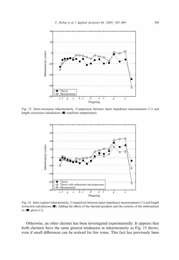
To correlate theoretical results and measurements, an input impedance measure-ment device is used (see [30]). It gives the acoustic linear response of the passiveinstrument (i.e. without reed e!ects) to an harmonic excitation. Measurements aremade in a well-insulated room and temperature is 18.5 "C. 5 The resonance frequen-cies are obtained by interpolating the imaginary part of the admittance in the vicinityof each resonance, the oscillating frequency satisfying Im$Y % " 0. The absoluteuncertainty on the measurements is estimated to be ±5 cents.
Figs. 13 and 14 show that agreement between experiment and theory is good, butfor few tones discrepancies are about 15 cents which can be explained by an incon-venient determination of the length ‘d when investigating the open hole e!ect. Fig. 14also shows the inter-register inharmonicity with conditions close to the normal use ofa clarinet, i.e. when both the thermal gradient and the conicity of the embouchure atthe end of the mouthpiece are taken into account. With the use of the geometry of aclassical embouchure (see [31]), the e!ect of the conical part at the end of the embou-chure has been evaluated with the exact formulae of length corrections given inAppendix A (see Eq. (A.3)). It appears that the embouchure conicity narrows theinharmonicity of the highest tones of the register up to 20 cents.
5 Two other changes in cross section occur in the experimental setup at the input of the instrument buttheir e!ect on the resonance frequencies is subtracted algebraically.
388 V. Debut et al. / Applied Acoustics 66 (2005) 365–409
Otherwise, an other clarinet has been investigated experimentally. It appears thatboth clarinets have the same general tendencies in inharmonicity as Fig. 15 shows,even if small di!erences can be noticed for few tones. This fact has previously been
e f g a b c’ d’ e’ f’ g’ a’"80
"60
"40
"20
0
20
40
Fingering
Inha
rmon
icity
(cen
ts)
TheoryMeasurements
Fig. 13. Inter-resonance inharmonicity. Comparison between input impedance measurements (s) andlength correction calculations (j) (uniform temperature).
e f g a b c’ d’ e’ f’ g’ a’"80
"60
"40
"20
0
20
40
60
80
Fingering
Inha
rmon
icity
(cen
ts)
TheoryTheory with embouchure and temperatureMeasurements
Fig. 14. Inter-register inharmonicity. Comparison between input impedance measurements (s) and lengthcorrection calculations (j). Adding the e!ects of the thermal gradient and the conicity of the embouchureto (j) gives (h).
V. Debut et al. / Applied Acoustics 66 (2005) 365–409 389

reported in [7] and is linked to di!erences in bore profile of the upper part of theinstrument. In the same reference, Fig. 11 shows results for two di!erent clarinets,very similar to the results of Fig. 15 for the inter-resonance inharmonicity: neverthe-less a tendency for the results of the present study is to be 5 cents lower than theresults for the clarinets measured in [7]. Moreover, adding the results for the inter-resonance inharmonicity and for the inharmonicity due to register hole leads to verysimilar inter-register inharmonicity results for the two studies.
3.7. Discussion and conclusions
(i) All our calculations deals with resonance frequencies and no excitation mecha-nism has been introduced. As shown by Figs. 11 and 16, our analysis leads tothe following statements concerning the origin of the general tendency of clar-inets to have tuning deficiencies for the lowest twelfths:* the used linear theory does not reveal a tuning problem for the lowest tones,* certain dimensions of the tone holes have been chosen by makers. When their
e!ects are considered as imposed, the remaining parameters to achieve a cor-rect tuning are mainly in the bore profile and the location of the register hole,
* a good compromise between the bell profile and the register hole location andsize, is needed to control the tuning of the lowest twelfth (tone e),
* the barrel and bore profile at the top end of the upper joint are of greatimportance in order to bring the lowest and middle twelfths in tune. Thise!ect tends to balance the e!ect of the closed holes over the entire scale.
e f g a b c’ d’ e’ f’ g’ a’"40
"30
"20
"10
0
10
20
30
40
50
Fingering
Inha
rmon
icity
(cen
ts)
Buffet Crampon ABuffet Crampon B
Fig. 15. Measured inter-register inharmonicities obtained from input impedance measurements for twoBu!et Crampon clarinet models.
390 V. Debut et al. / Applied Acoustics 66 (2005) 365–409

Finally, if positive inharmonicity of the resonator is observed for the lowesttwelfths, the origin of the problem may lie in combination of the action of reg-ister hole opening, cavities, bell and inappropriate bore perturbations in theupper part. Nederveen [1] has raised the question of the necessity of bore pert-urbations in musical instruments. In the case of the clarinet, calculations revealthe need to resort to bore irregularities close to the input to compensate for thenegative inharmonicity caused by open holes, cavities, flaring bell and disper-sion. Reaming the upper bore profile appears to be a di"cult task and mustbe done carefully, since this part seems to control the accuracy of the twelfths.
(ii) As discussed in Section 2, predicting playing frequencies from resonance curvesis not an easy task. Reference [7] shows that the measured length correction dueto the reed e!ects (volume velocity of the reed and reed damping) is rather con-stant over the entire first register and the first half of the second one, thenincreases strongly. This allows compensation for the large increase of inter-reg-ister inharmonicity shown e.g. in Fig. 15. Nevertheless this kind of measure-ment, done using an artificial mouth, is rather di"cult. It is also di"cult tocompare directly to the results obtained at di!erent levels by an instrumentalist.An example of this di"culty is given in [32]. From our results for the two clar-inets of Fig. 15, it is not possible to explain why the players are obtaining toolarge twelfths for the first tones (e to g). It is a subject for future investigation:may be the analysis could be made using also an artificial mouth, but the fact isthat the players often complain about too large twelfths, and this fact seems tobe quite common: as an example, recently Bu!et Crampon has designed a new
e f g a b c’ d’ e’ f’ g’ a’"80
"60
"40
"20
0
20
40
60
80
Fingering
Inha
rmon
icity
(cen
ts)
Holes/bell/register hole/dispersion/temperatureUpper partTotal
Fig. 16. Inharmonicities due to perturbations found in the upper part (barrel/change in cross-section/upper joint) (n), due to hole/bell/register hole/temperature/dispersion (s), and resulting total inter-registerinharmonicity (sum of the two curves) (j).
V. Debut et al. / Applied Acoustics 66 (2005) 365–409 391

clarinet, called Tosca,correcting the tone f. For these low tones, what is theoptimum inharmonicity of the resonator for having well tuned twelfth? Is itzero? The answer is not obvious, depending also on the excitation level sincethe resistance of a hole lowers the playing frequency (see ref. [35] and AppendixB), and certainly on the ‘‘tunability range’’ [16,11], due to several factors,including the modification of both the embouchure (reed opening and reeddamping) and the vocal tract. These musician-control parameters have notbeen extensively investigated yet. Moreover the ‘‘tunability range’’ increaseswith the pitch of the played tone: it is larger for the higher register than forthe lower one, particularly due to the low level of the second impedance peak(for the second register, the second peak corresponds to the fifth peak of thefirst register).
(iii) In the next sections, we continue our study in the same direction but in a dif-ferent perspective. First, the register hole is searched to allow a register jumpfor the 19-tone complete register. This is an alternative to what makers do sinceclarinettists use di!erent fingerings to play tones from f 0# to a 0# and their asso-ciated twelfths. Second, instead of working with a real instrument, we considera perfect cylindrical tube (without tone holes and flare) with only one registerhole. The next sections are devoted to the following general question: is it pos-sible to find a register hole location on a cylindrical tube, combined with a sim-ple perturbation in the upper part, which allows the first two complete registersto be perfectly well tuned? In other words, we examine if it is possible to designa well-tuned instrument which is provided with additional bore perturbations inthe upper part which exactly compensate for inharmonicities due to tone holesand other e!ects.
4. Optimization of the location of the register hole and tuning corrections: statement ofthe problem
4.1. Assumptions
Our goal now is to achieve harmonicity of the first two resonance frequencies f1and f2, for the e!ective lengths corresponding to each hole, i.e. between two extremevalues of ‘e!, written ‘min and ‘max. The precise intermediate values of the length iswithout importance for the present objective. As a consequence, the absolute e!ectof small discontinuities, e.g. cavities or tapers, is not important as well, only their rel-ative e!ect between these two registers being important. It is therefore convenient toconsider a continuous variation of the length between the two extreme values. Afterthe optimization of the intervals between the two registers for ‘e! 2 [‘min; ‘max], it willbe possible to find the precise location of the tone holes achieving the desired scale.
How can harmonicity between the frequency f1 of the tone of the first register andthe frequency f2 of the tone when the register hole is open, be achieved for all lengthsbetween ‘min and ‘max? First, we will find an optimal location for the register hole,
392 V. Debut et al. / Applied Acoustics 66 (2005) 365–409
located upstream of ‘min, second we will study if a correction system can compensatethe residual defaults of this register hole. The dimensions of the hole are consideredto be optimized by the practice of makers, and therefore are regarded as imposed. Itis actually a di"cult question, related to nonlinear e!ects as well as humidity, theimportant fact being that the linear behaviour, at low level, is well known [33].We do not take into account the use of the register hole as a B flat tone hole. Thecorrection systems are sought in order to be without manipulation by the instrumen-talist, and therefore to act on both the first and the second registers, contrary to theregister hole itself.
4.2. Formulation of the optimization problem
Optimization techniques are used to find a set of design parametersxH " fx$1%H ; . . . ; x$n%H g that can in some way be defined as optimal. These parametersare obtained by minimizing (or maximizing) a criterion function F which may besubject to constraints and/or parameter boundaries. Thus, the design parametersare subjected to the following requirements:
* small changes location must be less than the distance between the reed tip and thefirst tone hole;
* dimensions of the acoustical systems must be reasonable for the realization;* geometrical dimensions are positive.
Our optimization problem is formulated as follows:
minx2Rn
F$x% where F is the criterion function;
lbi 6 xi 6 ubi i " 1; . . . ; n;
(
$43%
where x is the vector of design parameters $x 2 Rn% and lbi and ubi are the lower andupper parameter boundaries, respectively, for the design parameter xi.
4.3. Criterion functions
4.3.1. Location of the register holeAs previously shown, the presence of the register hole suggests that it is probably
impossible to built a clarinet in a way that the two registers might be played perfectlyin tune with the same fingerings. Thus, the objective is to find the register hole loca-tion that entails the smallest frequency shift of the second resonance frequency for allfingerings. The first optimization is performed in order to play a 19-tone compass i.e.a complete register. Then, a second optimization is performed restricting attention tofingerings from e to f 0 (above this fingering, clarinettists do not use the same fingeringfor the fundamental and the associated twelfth). The distance ‘ of the hole from thee!ective input is the only design parameter. The optimization problem deals with Eq.(20) which predicts theoretically the frequency deviation associated with the openingof the register hole. It can be formulated with one of the two following criterions:
V. Debut et al. / Applied Acoustics 66 (2005) 365–409 393
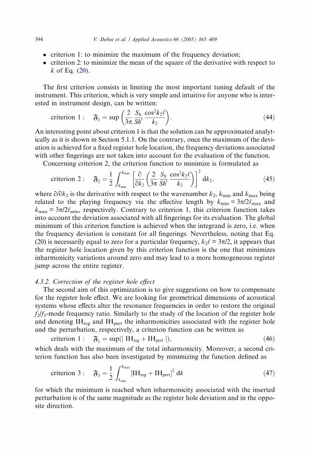
* criterion 1: to minimize the maximum of the frequency deviation;* criterion 2: to minimize the mean of the square of the derivative with respect to
k of Eq. (20).
The first criterion consists in limiting the most important tuning default of theinstrument. This criterion, which is very simple and intuitive for anyone who is inter-ested in instrument design, can be written:
criterion 1 : F1 " sup2
3pSh
Sh0cos2k2‘
k2
! ": $44%
An interesting point about criterion 1 is that the solution can be approximated analyt-ically as it is shown in Section 5.1.1. On the contrary, once the maximum of the devi-ation is achieved for a fixed register hole location, the frequency deviations associatedwith other fingerings are not taken into account for the evaluation of the function.
Concerning criterion 2, the criterion function to minimize is formulated as
criterion 2 : F2 "1
2
Z kmax
kmin
ook2
2
3pSh
Sh0cos2k2‘
k2
! "& '2dk2; $45%
where o/ok2 is the derivative with respect to the wavenumber k2, kmin and kmax beingrelated to the playing frequency via the e!ective length by kmin = 3p/2‘max andkmax = 3p/2‘min, respectively. Contrary to criterion 1, this criterion function takesinto account the deviation associated with all fingerings for its evaluation. The globalminimum of this criterion function is achieved when the integrand is zero, i.e. whenthe frequency deviation is constant for all fingerings. Nevertheless, noting that Eq.(20) is necessarily equal to zero for a particular frequency, k2‘ = 3p/2, it appears thatthe register hole location given by this criterion function is the one that minimizesinharmonicity variations around zero and may lead to a more homogeneous registerjump across the entire register.
4.3.2. Correction of the register hole e!ectThe second aim of this optimization is to give suggestions on how to compensate
for the register hole e!ect. We are looking for geometrical dimensions of acousticalsystems whose e!ects alter the resonance frequencies in order to restore the originalf2/f1-mode frequency ratio. Similarly to the study of the location of the register holeand denoting IHreg and IHpert the inharmonicities associated with the register holeand the perturbation, respectively, a criterion function can be written as
criterion 1 : F1 " sup$j IHreg # IHpert j%; $46%which deals with the maximum of the total inharmonicity. Moreover, a second cri-terion function has also been investigated by minimizing the function defined as
criterion 3 : F3 "1
2
Z kmax
kmin
(IHreg # IHpert)2 dk $47%
for which the minimum is reached when inharmonicity associated with the insertedperturbation is of the same magnitude as the register hole deviation and in the oppo-site direction.
394 V. Debut et al. / Applied Acoustics 66 (2005) 365–409

5. Results and discussions
For the optimization, the radius of the main tube is taken as R = 7.5 mm. Theheight of the register hole is 12.5 mm and its radius 1.55 mm. The upper boundfor the acoustical system location, is set to 154 mm which is the first tone hole loca-tion according to Table 1. The other parameter boundaries for all perturbations havebeen chosen in order to make the realization possible. Numerical results are per-formed with the minimisation routine fmincon from the MATLABMATLAB optimisationtoolbox.
5.1. Register hole location
5.1.1. Criterion 1: maximum of the frequency deviationAs mentioned earlier, an optimum of criterion 1 defined by Eq. (44) can be de-
rived analytically. In order to achieve the solution, we rewrite the frequency shiftas follows
IH " 2
3pSh
Sh‘cos2k2‘k2‘
; $48%
and note that the magnitude of the deviation is proportional to ‘ and varies as thefunction F(x) = cos2 x/x where x = k2‘. We will first prove that the maximum ofF(x) does not depend on ‘ for a certain interval of values of k2‘ and therefore theoptimum value of IH is obtained for the minimum of ‘ on this interval.
The e!ective length of the tube varies between ‘max = L = 585 mm, the total lengthof the instrument including reed and radiation length corrections, and ‘min. If thecompass of a register is one twelfth minus one semi-tone, the two extreme valuesof the e!ective length are related by ‘min = ‘max/2
18/12 which for simplicity we assumefirst to be ‘min = ‘max/3. The location of the register hole, defined by ‘, is in the upperpart of the instrument and satisfies ‘ < ‘min.
Then, for a given e!ective length, ‘e! lying between ‘min and ‘max, the wavenumberis defined as k2 = 3p/2‘e!, and therefore the argument of F(x) varies as follows:
3p‘2‘max
< k2‘ <3p‘2‘min
; $49%
thus
3p2
‘
L< k2‘ <
9p2
‘
L: $50%
Because the ratio ‘/L is less than 1/3, the upper bound for x = k2‘ is therefore 3p/2for which F(x) = 0. Fig. 17 shows the variation of F(x). From ‘ = L/3, for the intervaldefined by inequalities (50), F(x) varies from 0 and 0, with a maximum value equal to0.327, for x0 = 2.975. When ‘ decreases from L/3, Fig. 17 shows that the maximumvalues remains constant, equal to F(x0), except if ‘ becomes so small that the value ofF(x) for the minimum value of k2‘ reaches the same value 0.327. Using the subscriptsH for referring to the optimal value and (i) (i = 1–3) for referring to the studied
V. Debut et al. / Applied Acoustics 66 (2005) 365–409 395

criterion, this corresponds to ‘$1%H " 0:205L. Below this value, the maximum of F(x)grows rapidly. As a consequence, the optimum of IH for the criterion 1 is finallythe value ‘$1%H " 0:205L. Nevertheless, this value is not so critical, because the crite-rion function F1 for criterion 1 is linear with ‘, over the interval [0.205L, L/3], thusthe variation is not strong. Moreover, it appears clearly that any other criterion rel-ative to the maximum of the frequency deviation will lead to a value within the inter-val, because the maximum is reached two times instead of one only.
Finally, taking into account that the interval [‘min, ‘max] corresponds actually to aslightly smaller interval than a twelfth, i.e. 218/12, a numerical study leads to the opti-mal value for criterion 1 slightly smaller than ‘ = 0.205L, i.e. ‘$1%H " 0:2041L. Fig. 18confirms that for criterion 1, the function F1 increases linearly above this optimumvalue but increases strongly when ‘ decreases below it.
The register hole deviation obtained with this ‘‘optimal’’ position is plotted in Fig.19. As expected, the maximum of deviation appears at the beginning of the registerand is almost equal to a quarter tone. Moreover, this result shows that the registerhole is located close to its ideal position to produce the c 0/g00 transition: the registerhole is located at one third of the e!ective length for this fingering so that the fre-quency shift is zero.
5.1.2. Criterion 2: mean of the square of the derivative of the deviationThe register hole location achieved with the minimization of (45) is found to be
‘$2%H
L" 0:250; $51%
0.5 0.97 1.5708 2.97 4.71240
0.1
0.2
0.3
0.4
0.5
0.6
0.7
0.8
x
F(x)
Fig. 17. Perturbation function F(x) = cos2 x/x. The same local maximum is reached for x0 = 2.97 andx% = 0.97.
396 V. Debut et al. / Applied Acoustics 66 (2005) 365–409
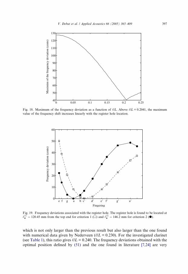
which is not only larger than the previous result but also larger than the one foundwith numerical data given by Nederveen (‘/L = 0.230). For the investigated clarinet(see Table 1), this ratio gives ‘/L = 0.240. The frequency deviations obtained with theoptimal position defined by (51) and the one found in literature [7,24] are very
0 0.05 0.1 0.15 0.2 0.2540
50
60
70
80
90
100
110
120
130
Max
imim
of t
he fr
eque
ncy
devi
atio
n (c
ents
)
Fig. 18. Maximum of the frequency deviation as a function of ‘/L. Above ‘/L = 0.2041, the maximumvalue of the frequency shift increases linearly with the register hole location.
e f g a b c’ d’ e’ f’ g’ a’0
10
20
30
40
50
60
Fingering
Freq
uenc
y de
viat
ion
(cen
ts)
Fig. 19. Frequency deviations associated with the register hole. The register hole is found to be located at‘$1%H " 120:45 mm from the top end for criterion 1 (h) and ‘$2%H " 146:2 mm for criterion 2 (d).
V. Debut et al. / Applied Acoustics 66 (2005) 365–409 397

similar: the a!e00 transition is correct and the frequency shift at the beginning of theregister is about 20 cents (see Fig. 19).
5.1.3. ConclusionPerforming optimization by minimizing the criterion functions defined by (44)
and (45) gives di!erent results and indicates that the final location of the register holeis the result of a compromise. However, as expected with Eq. (48), the magnitude ofthe maximum of deviation increases with the distance ‘ but very slightly for locationlarger than ‘/L = 0.2041. As a consequence, above this critical value, the location ofthe register hole is not so essential on this point of view and this explained the dif-ference in the register hole location observed by Nederveen and the investigated clar-inets for instance. Finally, it appears that a register hole location far from thee!ective input and above the critical value should be an interesting compromise inorder to improve the first twelfths of the register. Hence, we choose the location gi-ven by the optimization of criterion 2 that is ‘$2%H " 146:2 mm.
Restricting now attention to fingerings from e to f 0 (not up to a 0#) may be inter-esting in order to understand what instrument makers do. The result is that the opti-mization process converges to a position for the register hole between the twoprevious extreme values for the two criterion functions. Moreover, for the criterion1, the distance from the clarinet e!ective input is found to be ‘$1%H " 133:7 mm Thisresult corresponds very well to the location used by Nederveen in its calculation [1](i.e. ‘ = 135 mm). For that case, the twelfths at the bottom of the scale are still verylarge but the maximum of the frequency deviation, which is also obtained for thelowest tone, has noticeably fallen to 35 cents (see Fig. 20). Concerning criterion 2,the location is very close from the one found for the large compass.
5.2. Adjustments of natural frequencies by means of small changes of the bore
5.2.1. Overview of the possibilitiesAs mentioned earlier, the criterion is now to compensate for the frequency devi-
ation due to the register hole by means of small changes of the bore. We are lookingfor a solution localized in the upper part of the instrument, i.e. a solution acting forall fingerings. Looking at Table 3, only three systems give inharmonicity in the rightdirection: an abrupt change in cross section area with S 0 < S, a change of conicity atthe top end, and a localized enlargement or contraction. Concerning the case of aclosed cavity, it has been shown (see Fig. 5) that both positive and negative inharmo-nicity can be generated: in order to produce negative inharmonicity, the conditionk1‘ > p/4 which corresponds to playing frequencies larger than f1 = c/8‘max mustbe valid. Thus, the accuracy of the twelfths at the end of the second-register scale(from e 0 fingering) would be improved only.
5.2.2. Abrupt change in cross section area: S 0 < SFixing the radius of the tube downstream the discontinuity equal to 7.5 mm, the
upstream tube radius R 0 and the location ‘ of the discontinuity are used as optimi-zation variables. Performing optimization leads to the following results:
398 V. Debut et al. / Applied Acoustics 66 (2005) 365–409
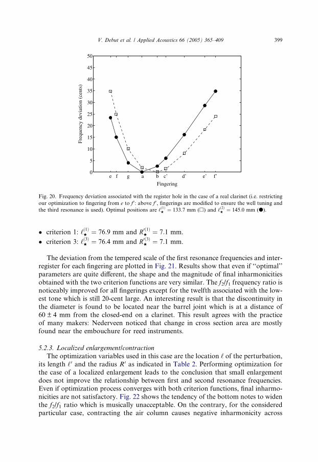
* criterion 1: ‘$1%H " 76:9 mm and R0$1%H " 7:1 mm.
* criterion 3: ‘$3%H " 76:4 mm and R0$3%H " 7:1 mm.
The deviation from the tempered scale of the first resonance frequencies and inter-register for each fingering are plotted in Fig. 21. Results show that even if ‘‘optimal’’parameters are quite di!erent, the shape and the magnitude of final inharmonicitiesobtained with the two criterion functions are very similar. The f2/f1 frequency ratio isnoticeably improved for all fingerings except for the twelfth associated with the low-est tone which is still 20-cent large. An interesting result is that the discontinuity inthe diameter is found to be located near the barrel joint which is at a distance of60 ± 4 mm from the closed-end on a clarinet. This result agrees with the practiceof many makers: Nederveen noticed that change in cross section area are mostlyfound near the embouchure for reed instruments.
5.2.3. Localized enlargement/contractionThe optimization variables used in this case are the location ‘ of the perturbation,
its length ‘ 0 and the radius R 0 as indicated in Table 2. Performing optimization forthe case of a localized enlargement leads to the conclusion that small enlargementdoes not improve the relationship between first and second resonance frequencies.Even if optimization process converges with both criterion functions, final inharmo-nicities are not satisfactory. Fig. 22 shows the tendency of the bottom notes to widenthe f2/f1 ratio which is musically unacceptable. On the contrary, for the consideredparticular case, contracting the air column causes negative inharmonicity across
e f g a b c’ d’ e’ f’0
5
10
15
20
25
30
35
40
45
50
Fingering
Freq
uenc
y de
viat
ion
(cen
ts)
Fig. 20. Frequency deviation associated with the register hole in the case of a real clarinet (i.e. restrictingour optimization to fingering from e to f 0: above f 0, fingerings are modified to ensure the well tuning andthe third resonance is used). Optimal positions are ‘$1%H " 133:7 mm (h) and ‘$2%H " 145:0 mm (d).
V. Debut et al. / Applied Acoustics 66 (2005) 365–409 399

the entire register and tends to improve the inharmonicity (see Fig. 23). The optimi-zation process converges to the following parameters:
criterion 1
‘$1%H " 62:74 mm;
‘0$1%H " 36:76 mm;
R0$1%H " 7:17 mm;
8>><
>>:criterion 3
‘$3%H " 60:0 mm;
‘0$3%H " 22:41 mm;
R0$3%H " 7:0 mm:
8>><
>>:
When minimizing the criterion function defined by Eq. (46), an interesting result isthat the design parameters given by the optimization process are very similar to thoseof a clarinet barrel. As for an abrupt change in cross section, the contraction is lo-cated at a point near the barrel joint. In addition, the acoustic length of the contrac-tion is the same as a common barrel (‘barrel + 40 mm). When looking at what makersdo, their practice varies considerably concerning the geometry of the barrel. How-
e f g a b c’ d’ e’ f’ g’ a’0
10
20
30
40
50
60
70
80
Fingering
Freq
uenc
y de
viat
ion
(cen
ts)
criterion 1criterion 3
e f g a b c’ d’ e’ f’ g’ a’"20
"10
0
10
20
30
40
50
60
Fingering
Inha
rmon
iciy
(cen
ts)
criterion 1criterion 3register hole
(a) (b)
Fig. 21. Frequency deviation for the first register (a) and inter-register inharmonicity (b): abrupt change incross section area. Minimisations of the two criteria give the same result: the f2/f1-frequency ratio isimproved for the highest notes but is still large for the lowest notes.
e f g a b c’ d’ e’ f’ g’ a’"50
"40
"30
"20
"10
0
10
20
30
40
50
Fingering
Freq
uenc
y de
viat
ion
(cen
ts)
criterion 1criterion 3
e f g a b c’ d’ e’ f’ g’ a’"20
"10
0
10
20
30
40
50
60
Fingering
Inha
rmon
iciy
(cen
ts)
criterion 1criterion 3register hole
(a) (b)
Fig. 22. Frequency deviation for the first register (a) and inter-register inharmonicity (b): localizedenlargement. Inter-register inharmonicity gets worse for the lowest notes which is musically unacceptable.
400 V. Debut et al. / Applied Acoustics 66 (2005) 365–409

ever, some makers insert narrower barrel than the cylindrical portion of the entireinstrument in order to get accurate twelfths in the upper part of the scale [34]. Whilethe results given by the minimization of (47) generate negative inharmonicity (seeFig. 23) the optimization process converges to two lower boundaries (R0$3%
H " R0max
and ‘$3%H " ‘min) When enlarging the domain where optimization variables are lookingfor, a new minimum (lower than the one found) is achieved. Thus, we do not con-sider this solution in the next. Finally, the mean value of inharmonicity is about!0.6 cents and the standard deviation of the mean value is equal to 11.9 cents.
5.2.4. Change in conicity at the inputThe optimization variables used for the case of tapered perturbation (see Table 2)
are the radius of the upper end of our model R 0, the top angle h and the locationpoint ‘. For each criterion function, the optimization process converges to the fol-lowing design parameters:
criterion 1
‘$1%H " 98:5 mm;
h$1%H " 0:10,;
R0$1%H " 7:46 mm;
8>><
>>:criterion 3
‘$3%H " 73:05 mm;
h$3%H " 0:22,;
R0$3%H " 7:37 mm:
8>><
>>:
The lengths of the tapered perturbations corresponding to criterion 3 and crite-rion 1 are about 44.5 mm and 46.5 mm which are both larger than the length of aclassic barrel. Concerning the location point, it is near the barrel joint for criterion3 and slightly below this point for criterion 1. An important thing to note is that thelocation achieved by the optimization process is always close to the barrel joint what-ever small change is used.
Fig. 24 shows final inharmonicities obtained with the minimization of the two cri-terion functions. The f2/f1-frequency ratio is improved globally across the entire scalefor both criterion functions except for the first fingering which is deteriorated slightlyfor criterion 3. As a consequence, only the design parameters given by the
e f g a b c’ d’ e’ f’ g’ a’0
5
10
15
20
25
30
35
40
Fingering
Freq
uenc
y de
viat
ion
(cen
ts)
criterion 1criterion 3
e f g a b c’ d’ e’ f’ g’ a’"20
"10
0
10
20
30
40
50
60
Fingering
Inha
rmon
iciy
(cen
ts)
criterion 1criterion 3register hole
(a) (b)
Fig. 23. Frequency deviation for the first register (a) and inter-register inharmonicity (b): localizedcontraction. Inter-register is improved across the entire register but remains large for the bottom notes.
V. Debut et al. / Applied Acoustics 66 (2005) 365–409 401

minimization of criterion 1 are considered. The mean value of the total inharmonic-ity is found to be 3.6 cents and the standard deviation of the mean value is about 11cents.
Finally, results indicate that the 20-cent deficiency still remains for the notes at thebottom of the scale whatever acoustic system is used in order to alter the resonancefrequencies. Thus, no improvement can be done to compensate for the e!ect of theregister hole except for tones at the end of the scale.
6. Conclusion
Many deviations from the standard cylindrical tube can be observed on a wood-wind instrument. The present work provides some theoretical results concerning thee!ects of these bore irregularities in the perspective of the relationship between thefirst two resonance frequencies for the two first registers. The calculations usingsmall perturbations are classical but the case of a side hole has been treated precisely,taking into account both the series and shunt impedances.
Calculations of inharmonicity associated with small perturbations and applica-tion to a real case give access to the relative influence on the first two resonance fre-quencies of each perturbating system found on a woodwind and reveal, in the case ofthe clarinet, the necessity to resort to bore perturbations to compensate for the dam-age on the resonance frequencies caused mainly by the presence of closed holes andthe register hole.
In addition, the use of simple optimization techniques has been shown to be usefulin order to give a more general view of the problem. However, optimization is verysensitive to the definitions of the criteria; for our purpose, performing optimizationon the accuracy of the twelfths does not impose a unique possible criterion. For in-stance, the use of optimization techniques with weight for the lowest tones is ofcourse possible and would probably give other results.
Fig. 24. Frequency deviation for the first register (a) and inter-register inharmonicity (b): positivetruncated cone. The f2/f1-frequency ratio is improved globally across the entire scale but it is still 20-centlarge for the lowest notes.
402 V. Debut et al. / Applied Acoustics 66 (2005) 365–409

The main results of the present work can be summarized as follows:
* the origin of the occurrence of wide twelfths for the lowest tones of a clarinet isnot to be found in shifts of the resonance frequencies of the resonator, as opposedto common wisdom. A way for future investigations may be the influences of theblowing parameters, reed parameters and the vocal tract since players can modifyboth of them and claim to do it.
* with a single corrective system, designing a new instrument having for the tworegisters a compass of a twelfth with the same fingering except the register holeopening, is impossible without tuning deficiencies;
* if the aim is the improvement of a common clarinet, the use of contractionsnear the barrel can help to some extent; nevertheless, no simple solution locatedin the upper part of the instrument can ensure the perfect tuning of the twelfthscorresponding to the first lowest tones.
Finally, combining global and local solutions, i.e. solutions acting mainly on oneparticular tone, is necessary in order to achieve the best tuning.
Acknowledgement
We wish to thank P. Mallet, J.P. Dalmont, O. Gipouloux and K. Nederveen forfruitful discussions, as well as J.P. Dalmont for a loan of the input impedance meas-urement device. The Laboratoire Kastler Brossel of the Departement de Physique del!ENS is a laboratoire associe au CNRS et a l!Universite Pierre et Marie Curie.
Appendix A. Exact calculation of length corrections
The aim of this appendix is to give some precise definitions and exact formulae forsome elements often encountered on wind instruments. Exact formulae can be usefulfor the computation of resonance frequencies by using an iterative procedure. Thegeometries of the di!erent elements are shown in Table 2.
A.1. Abrupt change in cross section
Looking for an equivalent system of section S, one can write at the discontinuity
!jY 0c tan k‘ " !jY c tan k$‘# D‘%;
where Y 0c " S0=qc and Y c " S=qc. Manipulating the above expression results in
kD‘ " Arctan12$a! 1% sin 2k‘
1# $a! 1%sin2k‘
!
; $A:1%
where a = S 0/S is the ratio of cross sections of the tubes located upstream and down-stream the discontinuity.
V. Debut et al. / Applied Acoustics 66 (2005) 365–409 403

A.2. Localized enlargement/contraction at the input of the instrument
Considering a localized enlargement or contraction of length ‘ 0 and cross sectionarea S 0 located at point ‘ and denoting a = S 0/S the change in diameter where S is thecross section area of the main tube, it can be written:
Y up1 " !jY c tan k‘ at point ‘;
Y down2 " !jY c tan k$‘# ‘0 # D‘% at point ‘# ‘0;
(
which results in after some algebra
kD‘ " Arctan tan k‘0TT 2 ! a$1# TT 2% # a2
!T tan k‘0 # a$1# TT 2% # a2 tan k‘0T 2
! ";
where T = tan k‘ and T2 = tan k(‘ + ‘ 0).Denoting a = 1 + X, the expression of the length correction becomes
kD‘ " Arctan X sin k‘0cos k$2‘# ‘0% # X cos k‘ cos k$‘# ‘0%
1# X cos2k‘0 # X $X # 2% sin k‘0 cos k‘ sin k$‘# ‘0%
! ":
$A:2%
In the limit that a is close to the unity, an approximation of Eq. (A.2) is given byEq. (31).
A.3. Truncated cone at the input
This paragraph deals with the case of a perturbation in taper of length ‘c locatedat distance ‘ from the reed tip. Calculations for a positive and a negative taper areidentical. The unique di!erence is that the sign of both quantities X and X 0 has to beinverted.
Assuming the quantities xi to be positive and x2 > x1 and noting that the twoinductances located at points ‘ and ‘ + ‘c are positive and negative, respectively,the following system is derived:
Y up2 " Y 2 # Y down2 at point ‘# ‘c $x2 > 0% and L > 0;
Y up1 " !Y 1 # Y down1 at point ‘ $x1 > 0% and L < 0;
Y down1 " !jY c tan k$‘# ‘c # D‘%;
8><
>:
where D‘ is the global length correction.Denoting X " ‘
x1and X 0 " ‘#‘c
x2, the result is
kD‘ " Arctan K; $A:3%
where
K "X cos2k$‘#‘c%
k$‘#‘c% ! X 0 cos2k‘k‘ # XX 0 cos k‘
k‘cos k$‘#‘c%k$‘#‘c% sin k‘c
1! 12X 0 sin 2k‘
k‘ # 12X sin 2k$‘#‘c%
k$‘#‘c% # XX 0 cos k‘k‘
sin k$‘#‘c%k$‘#‘c% tan k$‘# ‘c% sin k‘c
0
@
1
A:
404 V. Debut et al. / Applied Acoustics 66 (2005) 365–409

In the limit of small perturbation, the length correction for a truncated cone is thesum of the length correction associated with both changes in taper.
Appendix B. E!ect of the resistive term in the hole impedance on resonance frequencies
The aim of this appendix is to give an analytic expression of the playing frequencyin term of the resistive part R of the hole impedance. This can be interesting espe-cially when resistive e!ects are large and can occur at high level when nonlinear ef-fects appear, especially for narrow holes, like the register hole. This appendixdescribes the calculations which lead to the following expression for the frequencyof the played tone
f " f0 #Afc1#A
; $B:1%
where f0 and fc are the frequencies obtained when the resistance term is zero and infi-nite, respectively (when R is infinite, the e!ect of the hole disappears as it wasclosed), and A is a dimensionless factor given by
A " 2R
p
! "21
‘hole
L‘‘d # D‘
;
with L the total length of the resonator, ‘ the hole location, ‘d the distance from theopen end, ‘hole = h 0S/Sh and D‘ the equivalent length of the hole. The series imped-ances Za are assumed to be small (see Section 3.3.2), and thus, are neglected in thisappendix.
Using dimensionless impedance quantities, the impedance equivalent Zeq to thetone hole impedance and to the tube downstream the discontinuity can be writtenat the discontinuity point as
Zeq " Zh==Zdown;
where Zh " R# jX is the tone hole impedance and Zdown the impedance of the tubedownstream the discontinuity. Then, the input impedance Zin of the system can bederived as follows:
Z in "!t # jZhT
1#t2T!t
$ %
Zh1#t2T!t
) *# j
; $B:2%
where Zin is the input impedance of the system; Zh " R# jX is the tone hole imped-ance; t = tan k‘; T = tan kL.
For the resonance frequencies, the imaginary part of the input impedance van-ishes, i.e.
Im$Z in% " 0 () T ! t1# t2
# X! "
tT ! t1# t2
# XT! "
# TR2 " 0: $B:3%
V. Debut et al. / Applied Acoustics 66 (2005) 365–409 405

Denoting
A " sin k$L! 2‘% # sin kL# 2v cos kL;
B " cos k$L! 2‘% ! cos kL# 2v sin kL;
C " 2R2 sin 2kL;
where v = k‘hole, Eq. (B.3) can be rewritten in the form
AB# C " 0: $B:4%By writing kL = k1L + !1 where k1 is the wavenumber of the fundamental fre-
quency of the played tone defined as A = 0 (when R vanishes):
sin k1$L! 2‘% # sin k1L# 2v cos k1L " 0; $B:5%
the use of Taylor!s formula to the first order for the A and B quantities results in:
A " !1($L! 2‘% cos k1$L! 2‘% # L cos k1L# 2‘hole cos k1L! 2vL sin k1L); $B:6%
B " cos k1$L! 2‘% ! cos k1L# 2v sin k1L# !1(L sin k1L! $L! 2‘%& sin k1$L! 2‘% # 2‘hole sin k1L# 2vL cos k1L): $B:7%
Neglecting terms of second order in !1 and using Eq. (B.5), the quantity ABbecomes:
AB " 1
cos k1‘hole(L$1# cos 2k1‘% # 2‘holecos
2kL! 2‘ cos k$L! 2‘% cos kL! "
& cos 2k1‘d ! 1
cos k1L
! ": $B:8%
In the limit of k1‘d ' 1 (i.e. ‘d‘ and D‘
‘ are smaller than unity) and notingk1 " p
2$‘#D‘%,we have:
cos k1L " ! p2
‘2d‘$‘hole # ‘%
# o‘d‘
! ";
cos 2k1‘d " 1# o‘d‘
! ";
cos k1$L! 2‘% " sinp2
D‘# ‘d2
" p2
D‘# ‘d2
# o‘d‘
! ";
cos 2k1‘ " !1# o‘d‘
! ":
Substituting these results in Eq. (B.4) leads to the following equation
p2‘hole‘d # D‘
‘
! "!1 # 2R2 sin 2kL " 0:
Noting kL = kcL + !2 where kcL " p2(kc is the wavenumber when the hole is
closed), it can be written:
p2‘hole‘d # D‘
‘$k ! k1% # 4R2L$k ! kc% " 0; $B:9%
406 V. Debut et al. / Applied Acoustics 66 (2005) 365–409

therefore,
f " f0 #Afc1#A
; $B:10%
where
A " 2R
p
! "2 1
‘hole
L‘‘d # D‘
; $B:11%
f0 is the frequency of the tone with no resistance, and fc is the frequency of the tonewith an infinite resistance term.
A careful limiting process shows that Eq. (B.10) gives the expected behaviour forthe two extreme cases, i.e. when R ! 0 and R ! 1. In the limit that R goes to zero,the frequency f tends to f0, the frequency of the tone when the hole is open. In theopposite limit when R tends to infinity, the frequency f becomes fc. Fig. 25 showsthat the playing frequencies given by Eq. (B.10) coincide quite well with the playingfrequencies obtained by the zero values of the imaginary part of the input admit-tance. Moreover, in the limit that R is much smaller than unity, it follows
f " f0 #A$fc ! f0%: $B:12%
For a hole of radius r = 4.25 mm, height h = 6 mm, located at a distance ‘d = 80mm from the open end of a tube of length L = 0.650 m (this represents about a 12%decrease for the total length when the hole is open or more than a semitone for thefrequency shift) and for a resistive term R " 0:05, we obtain respectively a 12-centand a 5-cent decrease in pitch with equation (B.12) and the numerical simulation
0.2 0.4 0.6 0.8 1 1.2 1.4 1.6 1.8130
132
134
136
138
140
142
144
R
Freq
uenc
y (H
ertz
)
Im(Zin
)=0
Analytic formula
Fig. 25. Playing frequency as a function of the real part of the tone hole impedance (R = 7.5 mm, r = 4.25mm, h = 6 mm, ‘d = 80 mm, L = 0.650 m). In the limit that R ! 0, the frequency of the played tone tendsto fo, the frequency obtained when the hole is open. In the limit that R ! 1, the frequency of the playedtone approaches fc, the frequency when the hole being closed.
V. Debut et al. / Applied Acoustics 66 (2005) 365–409 407

from (B.3). Consequently, when the resistive term is not zero i.e. at high sound inten-sity, a frequency dependence is observed. We notice that a 10-cent decrease in pitch isaudible and this result suggests a way for future work to explain why musicians ob-serve a decrease in pitch for fortissimo levels [36].
References
[1] Nederveen CJ. Acoustical aspects of woodwind instruments. Illinois: Northern Illinois UniversityPress; 1969.
[2] McIntyre ME, Schumacher RT, Woodhouse J. On the oscillations of musical instruments. J AcoustSoc Am 1983;74(5):1325–45.
[3] Gilbert J, Kergomard J. Calculation of the steady-state oscillations of a clarinet using the harmonicbalance technique. J Acoust Soc Am 1989;86(1):34–41.
[4] Dalmont JP, Gilbert J, Kergomard J. Reed instruments, from small to large amplitude periodicoscillations and the Helmholtz motion analogy. Acta Acustica 2000;86:671–84.
[5] Hoekje PL. A brief summary of A.H. Benade!s wind instrument adjustment principles. Catgut AcoustSoc Am 1995;2(7):16–24.
[6] Meynial X, Kergomard J. Systemes micro-intervalles pour les instruments de musique a vent avectrous lateraux. J Acoustique 1988;1:255–70.
[7] Dalmont JP, Gazengel B, Gilbert J, Kergomard J. Some aspects of tuning and clean intonation inreed instruments. Appl Acoustics 1995;46:19–60.
[8] Kausel W. Optimization of brass instruments and its application in bore reconstruction. J New MusicRes 2001;30:69–82.
[9] Rendall FG. The clarinet: some notes on its history and construction, Instrument of theorchestra. London: Ernest Benn Limited; 1971. p. 50 (Chapter 5).
[10] Fobes CW. Available from http://www.clarkwfobes.com/articles.htm (1999).[11] Deplus G, Desurmont C, Fontaine R, Vidal D. Private communications, see appendix of Ref. [28]
(2004).[12] Rendall FG. The clarinet: some notes on its history and construction. London: Instrument of the
orchestra, Ernest Benn Limited; 1971. p. 34 (Chapter 4).[13] Baines A. Woodwind instruments and their history. Londres: Faber and Faber limited; 1977.[14] Grand N, Gilbert J, Laloe F. Oscillation threshold of woodwind instruments. Acustica
1996;82:137–51.[15] Benade AH. Fundamentals of musical acoustics. Londres: Oxford University Press; 1976. p. 394–5
(Chapter 20).[16] Leipp E. Acoustique et Musique. Paris: Masson; 1976.[17] Campbell M, Greated C. The musician!s guide to acoustics. London: J.M Dent and Sons Ltd; 1987.
p. 95 (Chapter 3).[18] Kergomard J. Ondes quasi-stationnaires dans les pavillions avec pertes visco-thermiques aux parois:
calcul de l!impedance. Acustica 1981;48(1):31–43.[19] Rayleigh L. The theory of sound, vol. 2, Dover Publications, Inc., New York, 1877, second edition, p.
66–8, 1945 re-issue (Chapter 12).[20] Keefe DH. Theory on the single woodwind tone hole. J Acoust Soc Am 1982;72(3):676–87.[21] Dubos V, Kergomard J, Khettabi A, Dalmont JP, Keefe DH, Nederveen C. Theory of sound
propagation in a duct with a branched tube using modal decomposition. Acta Acustica1999;85:153–69.
[22] Nederveen CJ, Jansen JKM, Van Hassel RR. Corrections for woodwind tone-hole calculations. ActaAcustica 1998;84:957–66.
[23] Dalmont JP, Nederveen CJ, Dubos V, Ollivier S, Meserette V, te Sligte E. Experimentaldetermination of the equivalent circuit of an open side hole: linear and non linear behaviour. ActaAcustica 2002;88:567–75.
408 V. Debut et al. / Applied Acoustics 66 (2005) 365–409

[24] Benade AH. Fundamentals of musical acoustics. Londres: Oxford University Press; 1976.[25] Keefe DH. Woodwind air column model. J Acoust Soc Am 1990;88:35–51.[26] Benade AH. Equivalent circuits for conical waveguides. J Acoust Soc Am 1988;88(5):1764–9.[27] Pierce AD. Acoustics: an introduction to its physical principles and applications. New-York: Acous-
tical Society of America; 1991. p. 534 (Chapter 10).[28] Debut V. Deux etudes d!un instrument de musique de type clarinette: analyse des frequences propres
du resonateur et calcul des auto-oscillations par decomposition modale. (to be published), Ph.D.thesis, Universite de la Mediterranee, Marseille (2004).
[29] Benade AH. On the mathematical theory of woodwind finger holes. J Acoust Soc Am1960;32(12):1591–608.
[30] Dalmont JP, Bruneau A-M. Acoustic impedance measurement: plane-wave mode and first helicalmode contribution. J Acoust Soc Am 1992;91(5):3026–33.
[31] Vergez C, Almeida A, Gauss R, Rodet X. Toward a simple physical model of double-reed musicalinstruments: influence of aero-dynamical losses in the embouchure on the coupling between the reedand the bore of the resonator. Acta Acustica 2003;89(6):964–73.
[32] Bak N, Domler P. The relation between blowing pressure and blowing frequency in clarinet playing.Acustica 1987;63:238–41.
[33] Van den Berg J. The influence of the register hole of a clarinet on its tuning., Tech rep, Laboratoired!Acoustique de l!Universite du Maine (2001).
[34] Brymer J. London: Clarinet, Macdonal and Jane!s; 1976.[35] Dalmont, JP, Ducasse E, Ollivier, S. Practical consequences of tone holes non-linear behaviour.
Proceedings of the International Symposium of Musical Acoustics, Perugia, pp. 153–156, 2001.[36] Dalmont JP, private communication.
V. Debut et al. / Applied Acoustics 66 (2005) 365–409 409