analysis and optimization of container lifting … file_enr...this is to certify that the synopsis...
TRANSCRIPT

ANALYSIS AND OPTIMIZATION OF CONTAINER LIFTING DEVICE
USED FOR SOLID WASTE MANAGEMENT
A SYNOPSIS SUBMITTED
FOR THE AWARD OF DEGREE OF
DOCTOR OF PHILOSOPHY
IN
MECHANICAL ENGINEERING
Submitted by
Prof. UTPAL VINODCHANDRA SHAH
Enrollment No. 139997119018
Associate Professor, Mechanical Engineering Department,
Government Engineering College, Modasa, Gujarat
Under Guidance of
Dr. Prof. G.H.Upadhyay Professor& Head, Mechanical Engineering Department
L.D. College of Engineering, Ahmedabad, Gujarat
GUJARAT TECHNOLOGICAL UNIVERSITY
AHMEDABAD

GUJARAT TECHNOLOGICAL UNIVERSITY
AHMEDABAD
CERTIFICATE
This is to certify that the synopsis entitled ―ANALYSIS AND OPTIMIZATION OF CONTAINER
LIFTING DEVICE USED FORSOLID WASTE MANAGEMENT has been undertaken and written under
my supervision and it describes the original research work carried out by UTPAL VINODCHANDRA
SHAH registered at Gujarat Technological University under the Faculty of Engineering in subject
(specialization) of Mechanical Engineering for the Degree of Doctor of Philosophy. To the best of
my knowledge and belief, this work has not been submitted elsewhere for any degree of any other
institution in India or abroad.
Supervisor’s Signature Dr. (Prof.) G.H.Upadhyay Professor& Head, Mechanical Engineering Department
L.D. College of Engineering, Ahmedabad
GUJARAT TECHNOLOGICAL UNIVERSITY
AHMEDABAD
DECLARATION I hereby certify that I am the sole author of this thesis and that neither any part of this thesis
nor the whole of the thesis has been submitted for a degree to any other University or
Institution. I certify that, to the best of my knowledge, my thesis does not infringe upon
anyone’s copyright nor violate any proprietary rights and that any ideas, techniques,
quotations, or any other material from the work of other people included in my thesis,
published or otherwise, are fully acknowledged in accordance with the standard referencing
practices. Furthermore, to the extent that I have included copyrighted material that
surpasses the bounds of fair dealing within the meaning of the Indian Copyright Act, I certify
that I have obtained a written permission from the copyright owner(s) to include such
material(s) in my thesis and have included copies of such copyright clearances to my
appendix. I declare that this is a true copy of my thesis, including any final revisions, as
approved by my thesis review committee. I also, attest that this thesis is free of plagiarism
of any kind and that I am fully aware of the Plagiarism Prevention Policy of Gujarat
Technological University, Ahmedabad.
Signature of candidate UTPAL VINODCHANDRA SHAH Enrollment No.: 139997119018 Date: Place: Ahmedabad
TABLE OF CONTENT Chapter No. Title Page No.
List of Tables………………………………………………………………. I
List of Figures……………………………………………………………… II
List of Abbreviations……………………………………………………. IV
1. Abstract 1
2. Solid waste management in Indian scenario 2
2.1 Objectives of the study 2 (a)
2.2 Scope of the work 2 (a)
2.3 Description of the research work 3
3. Design Methodology and Calculations 3
3.1 Design of Anchor Pin 4
3.2 Design Calculation of Hydraulic Cylinder 6
3.3 Design for pin joint 7
3.4 Design Calculation of Cross-Rod 8
3.5 Selection of Hoisting Chain Link for Container Lifting 9
3.5.1 Materials for chain link 10
4. Modelling and analysis of container lifting device 13
4.1 Dynamic Analysis of Container Lifting Device 13
4.1.1 Rigid dynamic analysis of CLD model 15
4.1.2 Transient dynamic analysis of CLD model 18
5. FFT Analyzer used for vibration measurement of hydraulic cylinder 26
5.1 VIBXPERT – FFT data collector and signal analyzer 26
6. Optimization in Hydraulic Cylinder Design 30
6.1 Single Objective Optimization Problem – Nonlinear Constrained 31
Minimization

Chapter No. Title Page No.
6.2 Multi Objective Optimization using Genetic Algorithm 33
6.3 Conclusion of optimization 40
7. Conclusion of Research work 41
7.1 Future scope of research work 43
REFERENCES 44
LIST OF PUBLICATIONS 50
I
LIST OF TABLES
Table No. Title of Table Page No.
Table 3.1 Grade 80 alloy chain standard by national association of 12
chain manufacturer
Table 4.1 Material and its property for individual component of CLD 14
Table 4.2 Joint applied to different pair of CLD component 14
Table 4.3 Analysis setting in rigid dynamic analysis of CLD model 15
Table 4.4 Rigid dynamic analysis setup for CLD model 16
Table 4.5 Value of translation joint force with respect to time 18
Table 4.6 Transient dynamic analysis setting 19
Table 4.7 Transient dynamic analysis setup of CLD model 19
Table 5.1 Typical measurements of RMS values 28
Table 6.1 Value of each variable Internal diameter (d), Thickness of Cylinder (t) 35
and Internal Pressure (p) after each iteration
Table 6.2 Value of each variable Internal diameter (d), Stress of Cylinder (s) 37
and Internal Pressure (p) after each iteration
Table 6.3 Value of each variable internal diameter (d), Thickness of Cylinder (t) 39
and Internal Pressure (p) after each iteration
Table 7.1 Comparison of results with allowable value 41

II
LIST OF FIGURES
Figure No. Title of Figure Page No.
Fig. 2.1 Process of solid waste management 2
Fig. 2.2 Truck mounted container lifting device 2 (a)
Fig. 3.1 Drawing of 4.5 CuM container used for CLD 4
Fig. 3.2 Drawing of anchor pin used in 4.5 CuM Container 4
Fig. 3.3 Cylindrical pin joints 8
Fig. 3.4 Drawing of Cross-rod used in CLD 8
Fig. 3.5 Model of chain link 10
Fig. 4.1 SolidWorks 3-D model of container lifting device 13
Fig. 4.2 Joints between individual components of CLD model 14
Fig. 4.3 Remote force, constrain, joint velocity, acceleration shown in CLD model 16
Fig. 4.4 Force shown on translation joint probe 17
Fig. 4.5 Translation joint force change with time 17
Fig. 4.6 Fine meshing of CLD model 18
Fig. 4.7 Time varying force applied on piston 19
Fig. 4.8 Time varying reaction force applied on cylinder 20
Fig. 4.9 Remote force, constrain, joint velocity, acceleration shown in CLD 20 model for transient analysis
Fig. 4.10 Von-Mises stress contour generated in CLD model 21
Fig. 4.11 Maximum Von-Mises stress generate in CLD model 21
Fig. 4.12 Maximum value of Von-Mises stress change with time 21
Fig. 4.13 Equivalent elastic strain contour generated in CLD model 22
Fig. 4.14 Maximum value of Equivalent elastic strain change with time 22
Fig. 4.15 Total deformation of CLD model 22
Fig. 4.16 Total deformation of CLD model with respect to time 23
Fig. 4.17 Cylinder- base total revolute joint probe force 23
Fig. 4.18 Time varying total cylinder- base revolute joint force 23
Fig. 4.19 Big link- base total revolute joint probe force 24
Fig. 4.20 Time varying total big link- base revolute joint force 24
Fig. 4.21 Big link- piston rod total revolute joint probe force 24
Fig. 4.22 Time varying total big link- piston rod revolute joint force 25

III
Figure No. Title of Figure Page No.
Fig. 4.23 Safety factor contour generate in CLD model 25
Fig. 4.24 Minimum time varying safety factor 25
Fig. 5.1 FFT spectrum of Hydraulic cylinder 28
Fig. 5.2 Some Photographs of actual readings taken of CLD by FFT analyser 30
Fig. 6.1 Optimization using MATLAB for the function: Minimization of 32
force value (f) exerted on piston
Fig. 6.2 Optimization using MATLAB for the function: Minimization of 33
Cross-sectional area (A) of the Hydraulic Cylinder
Fig. 6.3 Set of Non-inferior Solutions 34
Fig. 6.4 Pareto optimization using Genetic Algorithm plot of Stress 36 generated (N/mm2) v/s Force on Piston (N)
Fig. 6.5 Pareto optimization using Genetic Algorithm plot of Force (N) 38 v/s Thickness of Cylinder (mm)
Fig. 6.6 Pareto optimization using Genetic Algorithm plot of Force (N) 40 v/s Cross-sectional area of Cylinder (mm2)

IV
LIST OF ABBREVIATIONS
Sr. No. Abbreviations Meaning
1. MSWM Municipal Solid Waste Management
2. CLD Container Lifting Device
3. GUDC Gujarat Urban Development Corporation
4. HCV Heavy Commercial vehicles
5. LCV Light Commercial Vehicles
6. ISO International Organisation for Standardization
7. ULB Urban Local Bodies
8. FEA Finite Element Analysis
9. MATLAB Matrix Laboratory
10. WLL Working Load Limit
11. FFT Fast Fourier Transform
12. CFD Computational Fluid Dynamics
13. SWC Safe Working Capacity

1
1 Abstract
In all mega cities and municipal corporations, HCV chassis are used for loading and unloading
the containers having size more than 5.5 cubic meters. But for all towns and nagarpalikas, these
may not be preferred due to space limitations and narrow size roads. So in the case of towns
and nagarpalikas, tractor driven container lifting device may be used, which will lift up to 4.5
cubic meter containers. They can use containers of up to 4 - 4.5 cubic meters capacity, which
will make optimum use of the tractors. Even for more space limitations small containers
mounted on LCVs chassis can also be used.
It had been observed that mostly all municipal corporations are using 5.5 and 6 cubic meter
containers operated by a truck as the main source of waste collection and transportation. But
at ULBs, small towns and villages, it is very difficult to operate truck operated containers
because of following reasons:
1) Quantity of Solid waste to be handled is less as compare to Municipal Corporation.
2) Cost of truck operated container lifting device is also very high.
3) Narrow size of the roads and space limitations are also not allowing to use such solid
waste handling systems.
In this work, small container having capacity of 4.5 CuM is fabricated so that it can be operated
by tractor operated container lifting device. The idea was to design and develop new container
lifting device that can be used to handle 4.5 Cubic meter container which is to be operated by
tractor. As tractor is used to operate container lifting device, in the spare time it can be used to
operate trolleys, water tanker etc. at the Nagarpalikas. In short, tractor can be used to perform
multiple activities at Nagarpalika/ULB level. This combination can be made at less than half of
cost in comparison to the truck operated container lifting device.
The main focus of the research work is design and development of container lifting device that
can handle 4.5 Cubic meter container with the help of tractor. Work had been carried out for
design, failure analysis, vibration and FEA of various components of CLD, i.e. hydraulic cylinder,
link chain, different joints, cross bars, mechanical jack, leaf springetc. Hydraulic cylinder is the
2
most critical components of CLD, which is further optimized considering single and multi-
objective optimization problem using MATLAB.
The optimized design and modifications suggested in this work related to the CLD are
successfully implemented by GUDC and it is used in all ULBs in the state of Gujarat for solid
waste management. This CLD system is used to handle 4.5 Cubic meter container with the help
tractor to collect and transport municipal solid waste by various Nagarpalikas in Gujarat State.
2 Solid waste management in Indian scenario
Municipal Solid Waste Management (MSWM) is one of the major environmental problems of
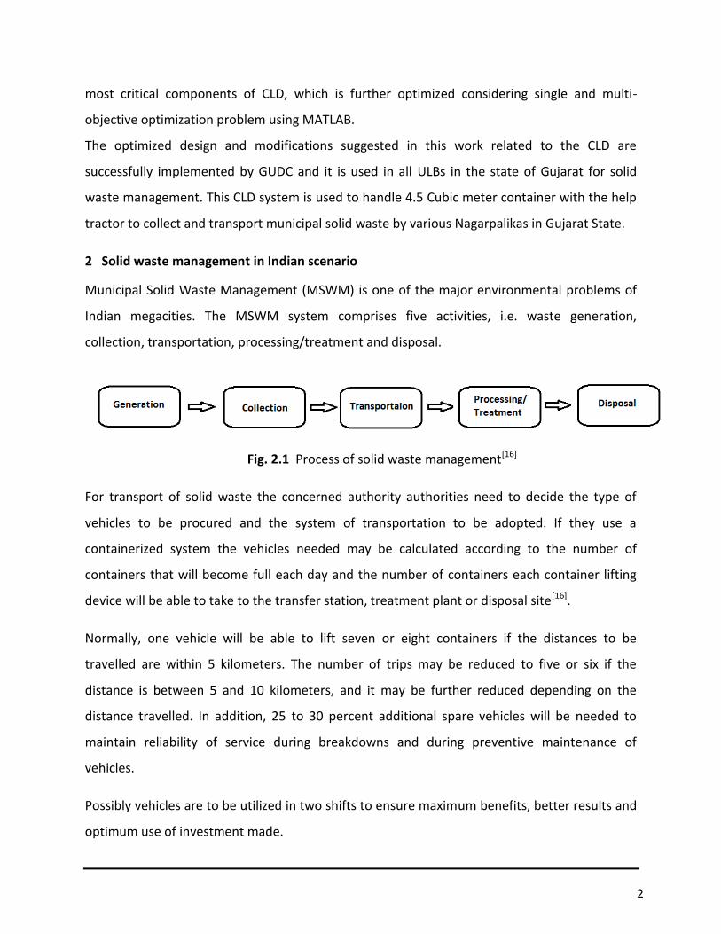
Indian megacities. The MSWM system comprises five activities, i.e. waste generation,
collection, transportation, processing/treatment and disposal.
Fig. 2.1 Process of solid waste management[16]
For transport of solid waste the concerned authority authorities need to decide the type of
vehicles to be procured and the system of transportation to be adopted. If they use a
containerized system the vehicles needed may be calculated according to the number of
containers that will become full each day and the number of containers each container lifting
device will be able to take to the transfer station, treatment plant or disposal site[16].
Normally, one vehicle will be able to lift seven or eight containers if the distances to be
travelled are within 5 kilometers. The number of trips may be reduced to five or six if the
distance is between 5 and 10 kilometers, and it may be further reduced depending on the
distance travelled. In addition, 25 to 30 percent additional spare vehicles will be needed to
maintain reliability of service during breakdowns and during preventive maintenance of
vehicles.
Possibly vehicles are to be utilized in two shifts to ensure maximum benefits, better results and
optimum use of investment made.

2 (a)
Fig. 2.2 Truck mounted container lifting device
2.1 Objectives of the study:
The main Objective of this study is to design the container lifting device operated with
tractors or LCVs used for small towns.
To determine the feasibility of improving performance of container lifting device for
solid waste management.
To identify the problems/difficulties faced with the existing design/specifications of the
container lifting device.
To identify significant parameters affecting performance of the container lifting device.
To review existing design/specifications of container lifting device.
To establish the improved design/specifications of the container lifting device that will
overcome most of the problems related the performance parameters.
2.2 Scope of the work:
Feasibility assessment through survey based on questionnaires from end users and
manufacturers of container lifting device.
Problem identifications based on survey conducted.
Identification of critical parameters will be assessed based on literatures available,
technical talk with experts and self-assessment of the actual operations cycle of the
existing systems.
Analysis tool will be used to finalize the most favorable design.

3
2.3 Description of the research work:
The detailed survey work for the different container lifting device will be done in the
first phase. It covers study and analysis of existing container lifting device used for the
solid waste management.
In second phase problems during operations and maintenance will be identified from
the all data collected.
Actual need base analysis will be done according to the requirement of solid waste
management.
Based on the above analysis new improved optimum utilization and convenient design
will be suggested for easy operation and less maintenance.
The same design will be checked using software as well as it will be checked
experimentally under AMC, AUDA and GUDC.
3 Design Methodology and Calculations
Selection of container to be used with tractor operated container lifting device is based
on volumetric capacity. Size of container is minimized based on operation and
performance criteria.
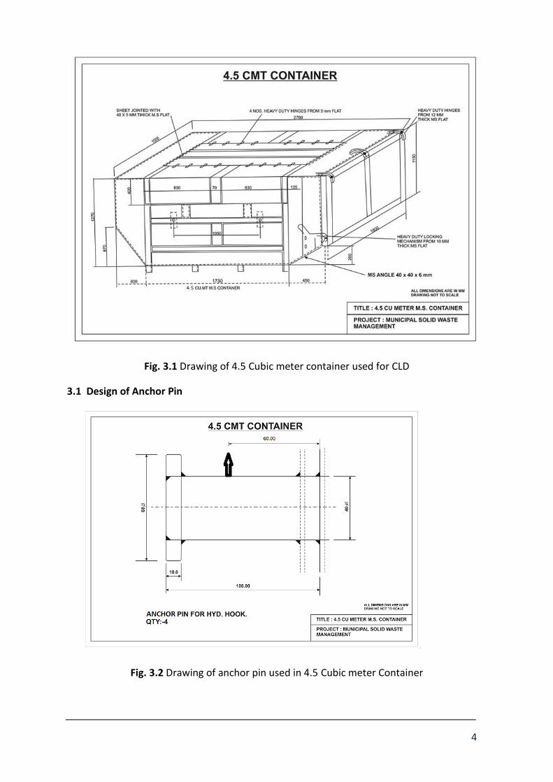
After detailed study and analysis 4.5 Cubic meter container is selected for the operation.
It is to be fabricate with Mild Steel sheets with four top openings and one rear lockable
tailgate with heavy-duty hinges as per below mentioned technical specifications and
drawing.
The lifting hooks/anchor pins shall be integrated within the frame and be capable of
taking the specified load.
4
Fig. 3.1 Drawing of 4.5 Cubic meter container used for CLD
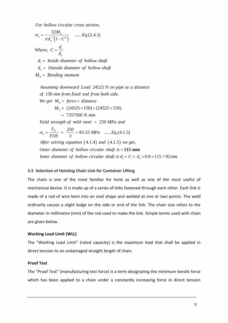
3.1 Design of Anchor Pin
Fig. 3.2 Drawing of anchor pin used in 4.5 Cubic meter Container

5
Bending moment equation in this case
........ . 3.1.1b
M YEq
I
,
b
Where
Bending stress
M Bending moment
Y Perpendicular distance between point of force and neutral axis
I Moment of inertia for circular cross section
2
250 /
2
yt
d Diameter of pin
S Yield strength of material N mm
FOS Factor of safety
Since there are four hook in the container for lifting purpose, so we divide the
maximum load of 5 ton by four to get the maximum load at single hook of container as
1.25 ton (12500 N).
Thus total force acting at single hook = 12500 N = 1.25 Ton
Using equation (3.1.1)
Where,
........ . 3.1.2yt
b
SEq
FOS
Using equation (3.1.1) and (3.1.2)
We get,
........ . 3.1.3yt
b
S M YEq
FOS I
Putting values in equation (3.1.3)
We get Diameter of pin, 39.39 40d mm mm

6
3.2 Design Calculation of Hydraulic Cylinder
ST52 is low carbon steel grade, excellent weldable, the most widely used steel grade
used for Hydraulic Cylinder Tubes. Normally supplied stressed relieved and
annealed or normalized. Hydraulic Cylinder Tubes ST52 and ST52.3 are found with excellent
machinability and weldability property. Supplied seamless, cold drawn & stress relieved
(BK+S), with yield strength over 520 MPa. The inside diameter is honed and oiled with the
tube ends capped for protection.[93]
ST52 Hydraulic Cylinder Tubes, applicable to machinery, hoists, automotive and transport
lifting equipment, waste disposal transport, food processing equipment, mechanical tools
and equipment, compressors and earth moving equipment etc. like hydraulic pressure,
pneumatic cylinder, oil pump barrel.
2
2 2
2
i
i
Pr essure RangeConsidered 160 to 200 kg / cm
200 9.81Pr essure,p N / mm 19.62 N / mm or MPa
100
Force,F Area,A Pr essure,p
5000 9.81 D 19.624
D 56.41mm 63mm
So, thediameter of piston rod is taken 63mmstandard.
The inside diameter is honed and oiled with the tube ends capped for protection.ISO
standard cylinder bore size is 32, 40, 50, 63, 80, and 100.
93
ult
ultt
For Hydrauliccylinder tube material issteel.
Hydraulic Cylinder Tube - ST52
Compressive/Tensile yieldstrength = 250MPa
Ultimate tensilestrength, = 520MPa
520104MPa
FOS 5

7
t ii
t i
O
i
O i
By Lame 's equation :
pD 63 104 19.62t 1 1
2 p 2 104 19.62
t 6.63 8 mm
By taking the ratioof externaldiameter of cylinder,D to
theint ernaldiameter of cylinder,D is1.75.
D 1.75 D 1.75 63 110 mm.
The piston rod size available with cylinder bore 110 mm is 63 mm.
2
cr 2
Buckling calculation for piston rod :
According to Euler 's equation,
n. .E.AP
L
K
cr
2
4
2
where, P Critical load (N) 5 ton 5000kg 49050 N
n end fixity coefficient
n 1 if both ends hinged
E 207000 N / mm
L 2900mm
.d
I d64K.dA 4
4
By putting all these values, weget d 45mm,
but in our caseint ernaldiameter is 63mm,henc
esafein buckling also.
3.3 Design for pin joint
Cylindrical pin joints are used in container lifting device mainly at three inter connection
between CLD base to hydraulic cylinders, hydraulic piston rod to big link and big link to
trailer base. Cylindrical pin joint are used to connect different component of CLD and help to
transmit motion between them. To sustain load and for proper functioning of CLD model it
is necessary to design cylindrical pin joint.

8
(A) (B) (C)
Fig. 3.3 Cylindrical pin joints
(A) base to hydraulic cylinders (B) hydraulic piston rod to big link (C) big link to trailer base.
For the design of the cylindrical pin, it can be fail in to double shear in loading condition.
Material selected for design of cylindrical pin is medium carbon steel.
P = 168000 N, y =400 MPa,
y = 400 * 0.58 = 232 MPa, F.O.S = 3
2
2
2
P P
A d
( A = )
2d = 2P
π y
FOS
d= 37.2 ≈ 40 mm
3.4 Design Calculation of Cross-Rod
Fig. 3.4 Drawing of Cross-rod used in CLD
9
3 4
32......
,
,
.(2.
4 1)1
.
bb
o
i
o
i
o
b
For hollow circular cross section
Where
Inside diameter of hollow shaft
Outside diameter of hollow shaft
MEq
d C
dC
d
d
d
M Bending moment
3.5 Selection of Hoisting Chain Link for Container Lifting
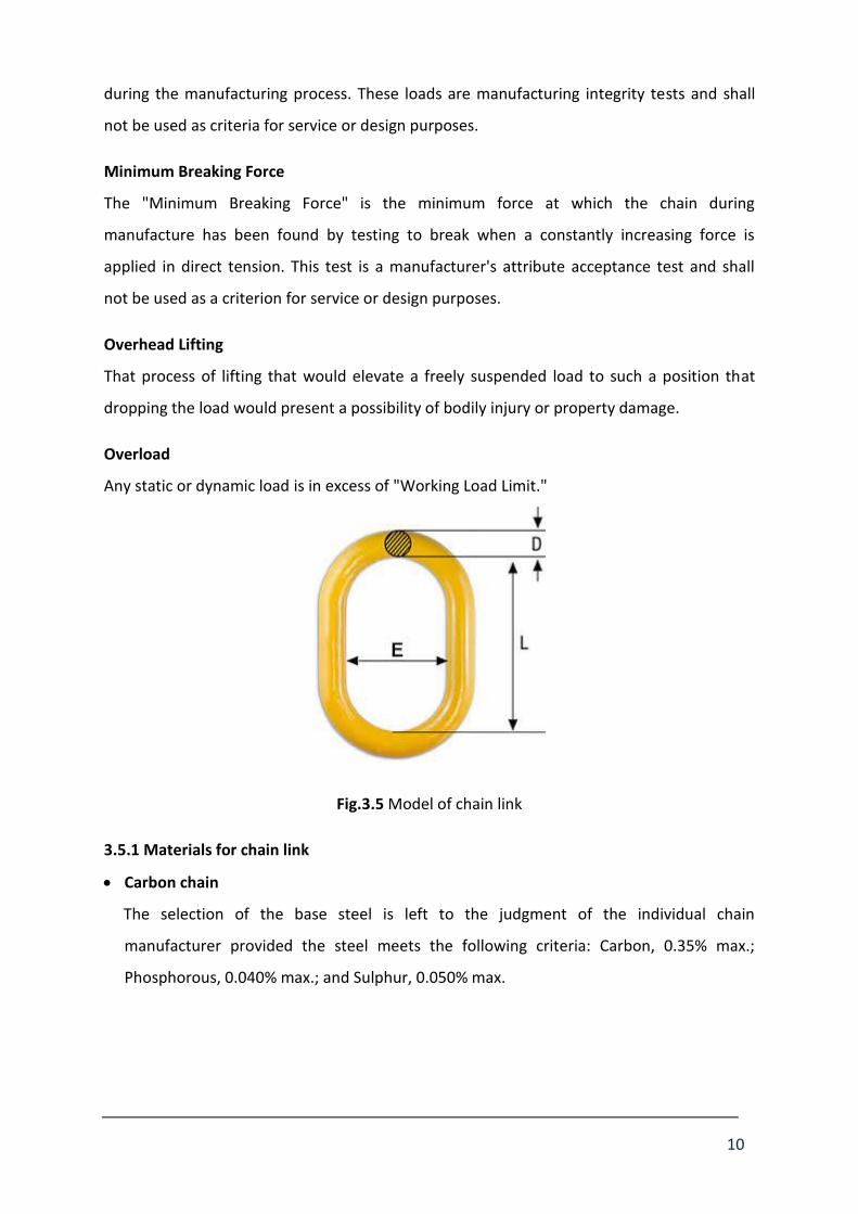
The chain is one of the most familiar for hoist as well as one of the most useful of
mechanical device. It is made up of a series of links fastened through each other. Each link is
made of a rod of wire bent into an oval shape and welded at one or two points. The weld
ordinarily causes a slight bulge on the side or end of the link. The chain size refers to the
diameter in millimetre (mm) of the rod used to make the link. Simple terms used with chain
are given below.
Working Load Limit (WLL)
The "Working Load Limit" (rated capacity) is the maximum load that shall be applied in
direct tension to an undamaged straight length of chain.
Proof Test
The "Proof Test" (manufacturing test force) is a term designating the minimum tensile force
which has been applied to a chain under a constantly increasing force in direct tension
24525 N
150 .
24525 150 24525 150 ( )
7357500 .
(
2
)
50
b
b
Assuming downward Load on pipe at a distance
of mm from fixed end from both side
We get force distance
M
N mm
Yield strength of mild steel MP and
M
a
...... .(4.1.5)
25083.3
,
33
4.1.4 4.1.5
0.8
115 =
yt
b
i o
Eq
After solving equation and we get
Outer diameter of hollow circular shaft is
Inner diameter of hollow circular shaf
SMPa
FOS
d Ct dis
115 mm
92mm
10
during the manufacturing process. These loads are manufacturing integrity tests and shall
not be used as criteria for service or design purposes.
Minimum Breaking Force
The "Minimum Breaking Force" is the minimum force at which the chain during
manufacture has been found by testing to break when a constantly increasing force is
applied in direct tension. This test is a manufacturer's attribute acceptance test and shall
not be used as a criterion for service or design purposes.
Overhead Lifting
That process of lifting that would elevate a freely suspended load to such a position that
dropping the load would present a possibility of bodily injury or property damage.
Overload
Any static or dynamic load is in excess of "Working Load Limit."
Fig.3.5 Model of chain link
3.5.1 Materials for chain link
Carbon chain
The selection of the base steel is left to the judgment of the individual chain
manufacturer provided the steel meets the following criteria: Carbon, 0.35% max.;
Phosphorous, 0.040% max.; and Sulphur, 0.050% max.

11
Alloy chain
The selection and amounts of the alloying elements in the steel are left to the judgment
of the individual chain manufacturer provided the steel meets the following criteria:
Carbon, 0.35% max.; Phosphorous, 0.035% max.; Sulphur, 0.040% max. Nickel must be
present in an alloying amount (0.40% min.), and at least one of the following elements
must be present in an alloying amount: Chromium (0.40% min.) or Molybdenum (0.15%
min.).
Stainless steel chain
The material shall be a 300 series austenitic stainless steel.
Now, selection of an open-link chain by using the following rule of thumb,
SWC = 28 D
SWC = Safe working capacity in tons
D = chain link diameter/thickness in inches
For a 5/8 “diameter chain link by using above equation,
SWC = 8× (5/8)2 = 3.125 tons

12
Table 3.1 Grade 80 alloy chain standard by national association of chain manufacturer [100]
Now according to loading situation of container while operation, chain link size should be
selected within working load limit of 8200 kg. So, as per the standard of National association
of chain manufactures for welded steel chain
Inside length (max) L = 51 mm
Inside width (min) E = 24 mm
Material diameter D = 16 mm = 5/8”
Working load limit (max) = 8200 kg
Min breaking force = 322 kN = 32834.86 kg
So we select the chain link from above table 4.1 for grade 80 alloy materials with 16 mm
diameter, inside width 24 mm and inside length of 51.2 mm.
4 Modelling and analysis of container lifting device

13
4.1 Dynamic Analysis of Container Lifting Device
Step 1) 3-D model of existing container lifting device build and assemble in SolidWorks 14.0
Fig. 4.1 SolidWorks 3-D model of container lifting device
Step 2)For perform Ansys dynamic analysis convert SolidWorks assembly file .SLDASM in to
Ansys .STEP file.
Step 3) Assign material property to each and every individual parts of container lifting
device.
Material and it’s property
Component of CLD modal
Hydraulic
cylinder
Piston
rod
Cross-rod Big link Base
Material ST 52 SAE 1045 S 355
Density (Kg/m3) 7800 7872 7800
Tensile Yield stress(Pa) 520 310 355
Compressive yield stress (Pa) 520 310 355
Ultimate stress (Pa) 900 565 470 - 630
Young’s Modulus (GPa) 200 200 210
Poisson's Ratio 0.3 0.29 0.3

14
Bulk Modulus (GPa) 167 158 175
Shear Modulus (GPa) 77 77.5 80.7
Table 4.1 Material and its property for individual component of CLD
Step 4) Generate geometry in ansys and give adequate connection between parts to
allowed motion like body to body or body to ground. In CLD model connection or joint
applied between parts are as follows…
Object name Type of joint Type of connection
Ground to base Fixed Body to ground
base to cylinder Revolute Body to body
cylinder to piston Translation Body to body
piston to big link Revolute Body to body
big link to base Revolute Body to body
cross rod to big link Fixed Body to body
Table 4.2 Joint applied to different pair of CLD component
Fig. 4.2 Joints between individual components of CLD model

15
4.1.1 Rigid dynamic analysis of CLD model
For rigid parts, the following conditions apply:
Line bodies cannot be set to rigid.
Multibody parts must have all bodies set to rigid.
Density is the only material property needed to calculate mass properties. All other
material specifications will be ignored.
An “Inertial Coordinate System” will automatically be defined at the centroid of the
part
Rigid bodies are rigid, so no stresses, strains, or relative deformation is calculated.
Hence, no mesh is required
Step 5) In Analysis setting number of step taken is one with end time is 60s.
Number Of Steps 1
Current Step Number 1
Step End Time 60. s
Auto Time Stepping on
Initial Time Step 1.e-002 s
Minimum Time Step 1.e-007 s
Maximum Time Step 5.e-002 s
Time Integration Type Runge-Kutta 4
Relative Assembly Tolerance on
Store Results At All Time Points
Table 4.3 Analysis setting in rigid dynamic analysis of CLD model
Step 6) In Rigid dynamic analysis CLD model setup like load, velocity, displacement etc.are
given below.

16
Table 4.4 Rigid dynamic analysis setup for CLD model
Fig. 4.3 Remote force, constrain, joint velocity, acceleration shown in CLD model
Step7) Aim to perform rigid dynamic analysis is to find out force generate at different joint
probe and working behaviour of model in 3-D space. After completion of solution result are
found are as follows.
Analysis setup Object name Value
Acceleration All body 9.8 m/s2 in global C. S. +y axis
Remote force Cross- rod 25000 N in global C. S. –y axis
Joint velocity Cylinder- piston pair 20 mm/s in reference C. S. +x axis
Remote
displacement
Cylinder, piston, big link 1) x displacement is 0 mm
2) rotation in y and z axis is 00

17
Fig. 4.4 Force shown on translation joint probe
Fig. 4.5 Translation joint force change with time
-2.00E+05
-1.50E+05
-1.00E+05
-5.00E+04
0.00E+00
5.00E+04
1.00E+05
1.50E+05
0 10 20 30 40 50 60 70
Forc
e (N
)
Time (Sec.)

18
Second Force(N) Second Force(N) Second Force(N)
0 1.12E+05 21 -7547.7 41 -60160
1 90991 22 -10081 42 -63323
2 76687 23 -12589 43 -66595
3 65865 24 -15079 44 -69992
4 57219 25 -17557 45 -73526
5 50034 26 -20029 46 -77218
6 43884 27 -22625 47 -81088
7 38497 28 -24978 48 -85161
8 33688 29 -27467 49 -89467
9 29330 30 -29971 50 -94043
10 25327 31 -32496 51 -98932
11 21611 32 -35047 52 -1.04E+05
12 18128 33 -37630 53 -1.10E+05
13 14837 34 -40250 54 -1.16E+05
14 11704 35 -42913 55 -1.23E+05
15 8703 36 -45624 56 -1.31E+05
16 5811.6 37 -48391 57 -1.39E+05
17 3011.7 38 -51220 58 -1.50E+05
18 288.1 39 -54118 59 -1.61E+05
19 -2372.4 40 -57095 60 -1.76E+05
20 -4981
Table 4.5 Value of translation joint force with respect to time
4.1.2 Transient dynamic analysis of
CLD model
Step5) Meshing is to be done by
automatic generate mesh option with
element shape used was tetrahedral.
Total numbers of element is 33790
with numbers of node is 69041.
Fig. 4.6 Fine meshing of CLD model

19
Step 6) In Analysis setting number of step taken is one with end time is 60s.
Number Of Steps 1
Current Step Number 1
Step End Time 60. s
Auto Time Stepping on
Initial Time Step 0.1 s
Minimum Time Step 0.1 s
Maximum Time Step 0.1 s
Time Integration on
Newton Raphson option Program control
Store Results At All Time Points
Table 4.6 Transient dynamic analysis setting
Step 7)In transient dynamic analysis CLD model setup like load, velocity, displacement etc.
are given below.
Table
4.7Transient dynamic analysis setup of CLD model
-200000
-150000
-100000
-50000
0
50000
100000
150000
1 3 5 7 9 11 13 15 17 19 21 23 25 27 29 31 33 35 37 39 41 43 45 47 49 51 53 55 57 59 61
Analysis setup Object name value
Acceleration All body 9.8 m/s2 in global C. S. +y
Remote force Cross- rod 25000 N in global C. S. -y
Joint velocity Cylinder- piston pair 20 mm/s in reference C. S. +x

20
Fig. 4.7 Time varying force applied on piston
Fig. 4.8 Time varying reaction force applied on cylinder
Fig. 4.9 Remote force, constrain, joint velocity, acceleration shown in CLD model for
transient analysis
Step 8) Aim to perform transient dynamic analysis is to find out time-history charts to
understand the transient response of the system. Like time varying stress, strain,
acceleration, joint force and moment etc. After completion of solution result are found are
as follows.
-150000
-100000
-50000
0
50000
100000
150000
200000
1 3 5 7 9 11 13 15 17 19 21 23 25 27 29 31 33 35 37 39 41 43 45 47 49 51 53 55 57 59 61

21
Fig. 4.10 Von-Mises stress contour generated in CLD model
Fig. 4.11 Maximum Von-Mises stress generate in CLD model
Fig. 4.12 Maximum value of Von-Mises stress change with time
0.00E+00
2.00E+07
4.00E+07
6.00E+07
8.00E+07
1.00E+08
1.20E+08
1.40E+08
1.60E+08
1.80E+08
0 1 0 2 0 3 0 4 0 5 0 6 0 7 0
VO
N-
MIS
ES S
TRES
S (P
A)
TIME (SEC.)

22
Fig. 4.13 Equivalent elastic strain contour generated in CLD model
Fig. 4.14 Maximum value of Equivalent elastic strain change with time
Fig. 4.15 Total deformation of CLD model
0.00E+00
1.00E-04
2.00E-04
3.00E-04
4.00E-04
5.00E-04
6.00E-04
7.00E-04
8.00E-04
9.00E-04
1.00E-03
0 10 20 30 40 50 60 70
Vo
n-
mis
es S
trai
n (
m/m
)
Time (Sec.)

23
Fig. 4.16 Total deformation of CLD model with respect to time
Fig. 4.17 Cylinder- base total revolute joint probe force
Fig. 4.18 Time varying total cylinder- base revolute joint force
0.00E+00
5.00E-01
1.00E+00
1.50E+00
2.00E+00
2.50E+00
3.00E+00
3.50E+00
4.00E+00
4.50E+00
0 10 20 30 40 50 60 70
DIS
PLA
CEM
ENT
(M)
TIME (SEC.)
0.00E+00
2.00E+04
4.00E+04
6.00E+04
8.00E+04
1.00E+05
1.20E+05
1.40E+05
1.60E+05
1.80E+05
0 10 20 30 40 50 60 70
Tota
l Fo
rce
on
Jo
int
(N)
Time (Sec.)

24
Fig. 4.19 Big link- base total revolute joint probe force
Fig. 4.20 Time varying total big link- base revolute joint force
Fig. 4.21 Big link- piston rod total revolute joint probe force
0.00E+00
2.00E+04
4.00E+04
6.00E+04
8.00E+04
1.00E+05
1.20E+05
1.40E+05
1.60E+05
1.80E+05
0 10 20 30 40 50 60 70
Tota
l Fo
rce
on
Jo
int
(N)
Time (Sec.)

25
Fig. 4.22 Time varying total big link- piston rod revolute joint force
Fig. 4.23 Safety factor contour generate in CLD model
Fig. 4.24 Minimum time varying safety factor
0.00E+00
2.00E+04
4.00E+04
6.00E+04
8.00E+04
1.00E+05
1.20E+05
1.40E+05
1.60E+05
1.80E+05
0 10 20 30 40 50 60 70
Tota
l Fo
rce
on
Jo
int
(N)
Time (Sec.)
0
1
2
3
4
5
6
0 10 20 30 40 50 60 70
Saft
ey F
acto
r
Time (Sec.)

26
Static Analysis of Leaf Spring and mechanical jack had been carried out with help of
SolidWorks 14.0. Stress analysis and FEA results in both cases are found satisfactory.
5 FFT Analyzer used for vibration measurement of hydraulic cylinder:
Hydraulic cylinders are one of the most important components of the hydraulic systems
used in a different industrial application. Design of a hydraulic cylinder consists of a different
loading and boundary conditions. Vibration of the cylinder during working condition is one
of the most crucial elements of the failure criterion. In the container lifting device operated
by tractor, the most critical part is two hydraulic cylinders of 5 ton capacity. It would be very
important to optimize the dynamic characteristics of hydraulic cylinders, because on the
case of they will have to carry out the operation with huge weight inertia. During the
analysis, the dynamic characteristics of hydraulic cylinders are obtained by using the Time
Capture Analysis and Real-time FFT, which is equipped on the container lifting device with
tractor used for solid waste management.
5.1 VIBXPERT – FFT (Fast Fourier Transform) data collector and signal analyzer:
• As the double acting hydraulic cylinder is most important element for container
lifting device.
• Actual run for measurement of vibrations for the same element at different 14
stages of lifting and lowering the empty and loaded 4.5 Cubic meter container with
container lifting device.
• Thus the vibrations of double acting hydraulic cylinder were measured taking the
different 14 stages readings. Out of that four samples are shown as under:

27
1) Empty container lifting acceleration spectrum
2) Loaded container lifting position 3 acceleration spectrum
3) Loaded container lifting position 4 displacement spectrum

28
4) Loaded container emptying position 8 velocity spectrum
Fig. 5.1 FFT spectrum of Hydraulic cylinder
Table 5.1 Typical measurements of RMS values
RMS Values
Sr. No.
Description Displacement (µm)
Velocity (mm/sec)
Acceleration (m/sec2)
1 Empty container lowering rest 10.05 1.01 0.193
2 Empty container lowering Vertical
24.38 2.42 0.271
3 Empty container lowering down 54.74 5.86 0.581
4 Empty container lifting 31.31 3.18 0.298
5 Loaded container lifting 1 26.15 3.20 0.349
6 Loaded container lifting 2 34.25 3.72 0.399
7 Loaded container lifting 3 15.98 1.75 0.197
8 Loaded container lifting 4 21.75 2.23 0.268
9 Loaded Container Emptying 5 41.04 4.43 0.476
10 Loaded Container Emptying 6 18.80 1.93 0.198
11 Loaded Container Emptying 7 43.45 3.79 0.359
12 Loaded Container Emptying 8 11.37 1.12 0.152
13 Loaded Container Emptying 9 43.98 4.38 0.427
14 Loaded Container Emptying 10 14.35 1.15 0.174

29
During actual working on CLD with FFT analyzer, vibration analysis of the hydraulic cylinder
under variable loading application and different boundary conditions is obtained. The main
cause of the vibration in hydraulic cylinder is stick-slip phenomenon between piston and
cylinder which is also responsible for the failure of a sealing material and reduces the fatigue
life as well the performance of the hydraulic system. Vibration analysis can be done by
static, dynamic and transient way. The Mode Superposition Method of a transient dynamic
analysis is one of the most important methods to predict mode shapes. All readings taken
were checked with the standard given and they are all falls within the limit hence it is
proved that hydraulic cylinders performance is safe in vibration.

30
Fig. 5.2 Some Photographs of actual readings taken of CLD by FFT analyser
6 Optimization in Hydraulic Cylinder Design
Monotonicity and dominance were used to find general principles for designing hydraulic
cylinders optimal for a wide class of objective functions and stress conditions. The design
method, although guaranteed to give the optimum design.
Optimal cylinders should be designed for minimum force. Only two designs can be
optimal—one with maximum pressure and minimum wall thickness; the other with
maximum stress.[102]
In the former case, the design is retained if and only if the stress is less than allowable.
Otherwise, a one-variable search in a restricted interval is needed. The results suggest the
potential importance of monotonicity and dominance in identifying the critical constraints in
a design.
Here we have taken six design variables,
(1) Inside diameter, d x(1) (2) Wall thickness, t x(2) (3) Material Stress, s (4) Force, f (5) Oil Pressure, p x(3) (6) Cross-sectional area of hydraulic cylinder, A

31
First Optimum design will be with maximum pressure and minimum wall thickness, second with maximum stress. Subject to
2 2
, 7
, 5 5000 49050
, 200 / 19.62 /
Wall thickness t mm
Force f ton so kg N
Pressure p kg cm say N mm
There are three physical relations: First relates force, pressure and area.
2
4f d p
The second gives the wall stress,
2
p ds
t
Also to find Cross-sectional area of hydraulic cylinder:
Cross-sectional area,
2
2
. . .
.
A d t t
A d t t
6.1 Single Objective Optimization Problem – Nonlinear Constrained Minimization
Optimization Toolbox provides widely used algorithms for standard and large-scale
optimization. These algorithms solve constrained and unconstrained continuous and
discrete problems. The toolbox includes functions for linear programming, quadratic
programming, binary integer programming, nonlinear optimization, nonlinear least squares,
systems of nonlinear equations, and multi-objective optimization. These can be used to find
optimal solutions, perform tradeoff analyses, balance multiple design alternatives, and
incorporate optimization methods into algorithms and models.
Using MATLAB 2012 following eight examples were created and solved related to
optimization and design hydraulic cylinder to be used for container lifting device, out of
these results for two examples are shown below:

32
Example 6.1 app2 -- Minimize the force, f
The iteration table in the command window shows how MATLAB searched for the minimum
value of force function in the unit disk. This table is the same whether to be used as
Optimization Tool or the command line. MATLAB reports the value of three variables (i.e.
internal diameter (d), cylinder wall thickness (t), pressure (p) and minimization of force, (f)
as below:
Output
x = 57.0000 7.0000 19.6200
fval = 5.0040e+04
Fig.6.1 Optimization using MATLAB for the function : Minimization of force value (f)
exerted on piston
Example 6.2
app16 – Minimization of cross-sectional area
Again the iteration table in the command window shows how MATLAB searched for the
minimum value of cross-sectional area function in the unit disk. This table is the same
whether to be used as Optimization Tool or the command line. MATLAB reports the value of
three variables (i.e. internal diameter (d), cylinder wall thickness (t), pressure (p) and
minimization of cross-sectional area, (A) as below:
Output
x = 50.0000 7.0000 16.0707
fval = 1.2529e+03

33
Fig.6.2 Optimization using MATLAB for the function : Minimization of Cross-sectional area
(A) of the Hydraulic Cylinder
6.2 Multi Objective Optimization using Genetic Algorithm
In many engineering disciplines we need to find solutions in the presence of conflicting
objectives. In such cases, solutions are chosen such that there are reasonable trade-offs
among different objectives. In certain problems, it may not be obvious that the objectives
are not conflicting to each other. In such combinations of objectives, the resulting Pareto-
optimal set will contain only one optimal solution. Pareto search is an approach for handling
such situations. Instead of generating a single optimal solution, many solutions are
generated that satisfy Pareto Optimality Criterion. According to this criterion, a solution
point P is accepted only if there are no solutions better than P with respect to all the
objectives. For example, even if P is worse than another solution P1 with respect to one
objective, P is accepted provided that it is better than P1 in at least one objective. Thus each
Pareto optimal solution is good in some respect. The set of all Pareto optimal solutions form
a surface known as a Pareto front. The Pareto front helps engineers understand the nature
of trade-offs that need to be made in order to select good solutions. Visualizing the front
helps engineers make good decisions.[62]
Definition: Point x is a non-inferior solution if for some neighbourhood of x there
does not exist a x such that x x and
, 1,...., ,
.
i i
j j
F x x F x i m and
F x x F x for at least one j
In the two-dimensional representation of Figure 4 the set of noninferior solutions lies on the
curve between C and D. Points A and B represent specific noninferior points.

34
Fig.6.3 Set of Non-inferior Solutions
A and B are clearly noninferior solution points because an improvement in one objective, F1,
requires a degradation in the other objective, F2, i.e. , 1 1 2 2, .B A B AF F F F
Since any point in that is an inferior point in which improvement can be attained in all
the objectives, it is clear that such a point is of no value.
Multi-objective optimization is, therefore, concerned with the generation and selection of
noninferior solution points.
Noninferior solutions are also called Pareto optima. A general goal in multi-objective
optimization is constructing the Pareto optima.
Using MATLAB 2012 ten different examples were created and solved related to multi-
objective optimization and design hydraulic cylinder to be used for container lifting device,
out of these results for following three examples are shown.
Example 6.3 app9 -- Multi objective Optimization, Pareto Optimization, Maximize the stress, s & Minimization of force, f linked with mymulti4.m. [d = x(1), t = x(2) and p = x(3)] App9
options = gaoptimset('PopulationSize',60,... 'ParetoFraction',0.7,'PlotFcns',@gaplotpareto); [xfval flag output population] = gamultiobj(@mymulti4,3,... [],[],[],[],[55,7,15.696],[70,15,19.62],options)
mymulti4.m function f = mymulti4(x)

35
f(1) = -x(3)*x(1)/(2.0*x(2)); f(2) = 0.785*x(1)^2*x(3);
Sr. No.
Internal Diameter, d, x(1) in
mm
Thickness of
Cylinder, t, x(2) in mm
Internal Pressure, p,
x(3) in N/mm2
Sr. No.
Internal Diameter, d, x(1) in mm
Thickness of Cylinder, t, x(2) in mm
Internal Pressure, p,
x(3) in N/mm2
1 55.0000 7.0000 15.6960
31 55.0000 7.0000 15.6960
2 66.2678 7.0059 19.5723
32 58.3710 7.0075 19.4684
3 55.0000 7.0000 15.6960
33 55.8222 7.0116 19.4376
4 55.0000 7.0000 15.6960
34 64.7664 7.0126 19.4935
5 62.4450 7.0580 19.4929
35 62.5167 7.0069 19.5045
6 60.4970 7.0069 19.5850
36 55.7202 7.0073 18.6119
7 60.1910 7.0055 19.4753
37 63.0392 7.0155 19.5742
8 64.0234 7.0124 19.5256
38 65.2111 7.0204 19.5760
9 55.0613 7.0047 18.4560
39 64.4622 7.0227 19.5644
10 55.1285 7.0795 16.5295
40 59.3725 7.0063 19.4064
11 55.1080 7.0361 16.1410
41 66.3172 7.0970 19.4580
12 61.5908 7.0063 19.4276
42 60.1721 7.0188 19.1510
13 55.5851 7.0042 17.1733
43 56.3911 7.0056 19.4793
14 58.2347 7.0028 19.5183
44 59.6663 7.0058 19.0352
15 55.1813 7.0154 18.4295
45 55.1911 7.0041 16.6825
16 57.9182 7.0066 19.5054
46 61.1807 7.0069 19.5383
17 64.9375 7.0077 19.5621
47 61.8250 7.0066 19.5524
18 66.0774 7.0193 19.4926
48 65.9791 7.0154 19.5238
19 65.4093 7.0061 19.5791
49 56.3966 7.0052 19.5736
20 55.3754 7.0041 18.4095
50 55.0618 7.0129 18.2643
21 58.5363 7.0245 19.5747
51 55.4177 7.0050 19.1041
22 62.7189 7.0064 19.5771
52 57.7819 7.0059 19.4920
23 57.4923 7.0119 19.4306
53 55.0702 7.0042 16.4860
24 63.2921 7.0069 19.4777
54 66.2678 7.0059 19.5723
25 55.7036 7.0036 16.5999
55 55.1476 7.0629 17.2362
26 56.2273 7.0055 19.4126
56 55.1774 7.0132 17.7655
27 61.5269 7.0458 19.3891
57 55.0156 7.0000 15.6960
28 55.7098 7.0088 19.3550
58 55.0963 7.0109 19.4399
29 63.4252 7.0314 19.5727
59 61.5894 7.1083 19.5141
30 55.3446 7.0098 17.8110
60 60.5595 7.1319 19.5850
Table 6.1 Value of each variable Internal diameter (d), Thickness of Cylinder (t) and Internal
Pressure (p) after each iteration

36
Fig.6.4 Pareto optimization using Genetic Algorithm plot of Stress generated (N/mm2) v/s
Force on Piston (N)
Example 6.4
app6 -- Multiobjective Optimization, Pareto Optimization, Maximize the force, f& Minimization of thickness, t linked with mymulti1.m. [d = x(1), s = x(2) and p = x(3)]
App6
options = gaoptimset('PopulationSize',60,... 'ParetoFraction',0.7,'PlotFcns',@gaplotpareto); [xfval flag output population] = gamultiobj(@mymulti1,3,... [],[],[],[],[55,80,15],[80,92,19.62],options)
mymulti1.m
function f = mymulti1(x) f(1) = -0.785*x(1)^2*x(3); f(2) = x(3)*x(1)/(2.0*x(2));

37
Sr. No.
Internal Diameter, d, x(1) in
mm
Stress of Cylinder, s,
x(2) in N/mm2
Internal Pressure, p,
x(3) in N/mm2
Sr. No.
Internal Diameter, d, x(1) in mm
Stress of Cylinder, s,
x(2) in N/mm2
Internal Pressure, p,
x(3) in N/mm2
1 55.0078 91.6168 15.0018
31 69.1143 91.7195 15.1666
2 79.9919 91.7703 19.6176
32 59.2841 91.8107 15.5315
3 79.9919 91.7547 19.6176
33 79.7091 91.7845 16.0754
4 79.2017 91.7932 16.5609
34 79.8247 91.7922 17.2598
5 55.0078 91.6480 15.0018
35 65.0814 91.7806 15.2036
6 55.0078 91.6793 15.0018
36 79.6472 91.7693 16.2253
7 79.9694 91.8333 19.3448
37 57.2698 91.7542 15.1802
8 79.8608 91.7727 15.8229
38 79.6972 91.7660 18.5507
9 66.3763 91.7202 15.1005
39 61.4632 91.7095 15.1355
10 76.0792 91.7928 15.0875
40 62.8751 91.6910 15.1317
11 79.4116 91.7394 17.0860
41 55.0078 91.6793 15.0018
12 79.8643 91.8274 19.0110
42 57.5984 91.7088 15.0473
13 63.2734 91.7015 15.0096
43 78.8803 91.7897 15.8159
14 79.8288 91.7790 17.8853
44 68.5697 91.7179 15.2937
15 65.0628 91.7493 15.2036
45 79.1919 91.7576 17.0069
16 64.9417 91.6681 15.0416
46 59.2251 91.6635 15.1759
17 77.6260 91.7956 15.2363
47 78.6092 91.7721 17.4948
18 67.0868 91.7160 15.3411
48 73.1853 91.7286 15.5022
19 70.5506 91.6568 15.0636
49 76.8068 91.7216 15.4737
20 75.3182 91.7606 15.3205
50 75.4550 91.8006 15.3853
21 67.3269 91.7229 15.0905
51 68.5267 91.7862 15.0148
22 79.3568 91.7997 16.7358
52 78.1924 91.7886 15.5452
23 79.6428 91.7405 18.5703
53 79.9295 91.7737 19.3981
24 79.9240 91.8879 17.5826
54 72.4331 91.7462 15.4561
25 79.9256 91.8502 18.3170
55 79.7663 91.7790 17.8853
26 77.3328 91.8284 15.1115
56 70.4219 91.7718 15.4908
27 72.7814 91.7847 15.0560
57 79.9240 91.8254 17.5826
28 79.8332 91.8116 18.7950
58 63.2734 91.6390 15.0643
29 59.9086 91.7026 15.4638
59 55.0586 91.7418 15.0018
30 56.6810 91.7107 15.0201
60 79.5994 91.7578 15.6826
Table 6.2 Value of each variable Internal diameter (d), Stress of Cylinder (s) and Internal
Pressure (p) after each iteration

38
Fig.6.5 Pareto optimization using Genetic Algorithm plot of Force (N) v/s Thickness of
Cylinder (mm)
Example 6.5
app17 -- Multiobjective Optimization, Pareto Optimization, Maximize the force, f& Minimization of cross-sectional area,Alinkedwith mymulti17.m. [d = x(1), t = x(2) and p = x(3)] options = gaoptimset('PopulationSize',60,... 'ParetoFraction',0.7,'PlotFcns',@gaplotpareto); [xfval flag output population] = gamultiobj(@mymulti17,3,... [],[],[],[],[55,07,15.696],[70,16,19.62],options)
mymulti17.m
function f = mymulti17(x) f(1) = -0.785*x(1)^2*x(3); f(2) = 3.14*((x(1)*x(2)+x(2)^2));

39
Sr. No.
Internal Diameter, d, x(1) in
mm
Thickness of
Cylinder, t, x(2) in mm
Internal Pressure, p,
x(3) in N/mm2
Sr. No.
Internal Diameter, d, x(1) in mm
Thickness of Cylinder, t, x(2) in mm
Internal Pressure, p,
x(3) in N/mm2
1 55.0000 7.0000 16.0085
31 55.4372 7.0396 19.2665
2 69.9987 7.0283 19.6200
32 65.5574 7.0109 19.6028
3 69.9987 7.0127 19.6200
33 55.9352 7.0152 19.5074
4 57.6986 7.0018 19.5913
34 55.3623 7.0012 18.9455
5 55.0031 7.0002 18.8725
35 63.8330 7.0108 19.3648
6 63.5562 7.0312 19.5854
36 69.6822 7.0121 19.6186
7 55.0000 7.0000 17.5416
37 64.9928 7.0043 19.5858
8 55.0000 7.0000 16.0085
38 65.8195 7.0137 19.6042
9 55.0000 7.0000 16.0241
39 60.3892 7.0092 19.5858
10 55.0000 7.0000 16.9024
40 59.5785 7.0034 19.2825
11 55.0031 7.0012 18.8725
41 61.5670 7.0146 19.6042
12 56.7591 7.0100 19.6194
42 57.3518 7.0055 19.4248
13 69.2413 7.0112 19.6099
43 65.6511 7.1359 19.6028
14 68.5541 7.0106 19.5913
44 55.1262 7.0001 18.3711
15 56.3311 7.0160 19.5552
45 59.4147 7.0100 19.4629
16 55.0000 7.0000 16.3537
46 58.3674 7.0041 19.2737
17 69.9987 7.0225 19.6200
47 55.2397 7.0133 19.3382
18 61.9767 7.0049 19.6109
48 62.2097 7.0236 19.4095
19 69.9987 7.0127 19.6200
49 63.2301 7.0185 19.6084
20 66.5631 7.0163 19.6021
50 60.8089 7.0126 19.6011
21 59.7798 7.0104 19.6011
51 57.7745 7.0087 19.3398
22 55.0012 7.0001 18.3711
52 59.3529 7.0099 19.3541
23 62.3718 7.0077 19.4629
53 68.9767 7.0144 19.5854
24 63.9051 7.0162 19.6023
54 56.8451 7.0144 19.5399
25 67.5167 7.0110 19.4657
55 67.1126 7.0062 19.5764
26 60.9584 7.0099 19.3632
56 67.1009 7.0032 19.5319
27 55.0000 7.0000 17.0923
57 55.7167 7.0280 19.4999
28 67.5035 7.0199 19.6129
58 62.8502 7.0158 19.6097
29 68.0485 7.0104 19.6050
59 57.6018 7.0055 19.4248
30 58.8005 7.0098 19.2952
60 66.5631 7.0163 19.3521
Table 6.3 Value of each variable internal diameter (d), Thickness of Cylinder (t) and Internal
Pressure (p) after each iteration

40
Fig. 6.6 Pareto optimization using Genetic Algorithm plot of Force (N) v/s Cross-sectional
area of Cylinder (mm2)
6.3 Conclusion of optimization
Most real-world search and optimization problems are naturally posed as multi-objective
optimization problems. However, due to the complexities involved in solving multi-objective
optimization problems and due to the lack of suitable and efficient solution techniques, they
have been transformed and solved as single objective optimization problems. Moreover,
because of the presence of conflicting multiple objectives, a multi-objective optimization
problem results in a number of optimal solutions, known as Pareto-optimal solutions. One
major drawback in of developing Pareto-optimal plots is the extensive calculation required
to obtain the complete curve. Hence MATLAB is used to overcome such problems.
Pareto optimization is a methodology for solving multicriteria decision problems. This
methodology provides a systematic approach towards design problems with multiple
conflicting objectives. In Pareto optimal design situations, the designer has more than one
performance measure of interest. An optimal solution is generally defined as the best

41
solution. However, with multicriteria problems, the "best" is often dependent upon a
designer's preferences. The Pareto optimization methodology usually generates a large
number of alternatives which the designer evaluates in order to arrive at his best solution
often termed the best compromise solution.
7 Conclusion of Research work
Container lifting device for maximum load carrying capacity about 5000 Kg and that can
handle container about 4 to 4.5 m3 is designed. To find its behavior in dynamic environment
rigid and transient structure dynamic analysis has been carried out. Results of analysis are
discussed and suggested modifications in CLD to eliminate operational issues and improving
its performance. From the above work final conclusions are derived asunder:
1) As per the dynamic analysis of CLD model, results of Von-Mises stress and strain, safety
factor etc. are found much below then allowable values. Comparison is given below.
Component Result Maximum value
generated
Allowable
value
Safety factor
during design
Safety factor
in Ansys result
Piston rod Stress 64.5 MPa 310 MPa 3 4.7
Cross- rod Stress 52 MPa 355 MPa 3 6.8
Big link Stress 169 MPa 355 MPa - 2.2
Base Stress 129 MPa 355 MPa - 2.8
Piston Stress 30 MPa 310 MPa 3 10
All body Strain 0.00086 0.002
Table 7.1 Comparison of results with allowable value
So, from the table it is found that maximum stress and strain generated during operation
of CLD model at maximum load is within prescribed limit.
2) As per the static analysis of leaf spring, simulated in Ansys 15, at design load maximum
stress generated is found 813 MPa, which is less than 1800 MPa (yield stress) with safety
factor of 2 considered in design. That indicate design is safe under working condition.
3) As per the static analysis of mechanical jack, simulated in Ansys 15, at design load
maximum stress generated is found nearly 90 MPa which is less than 170 MPa (yield
stress) with safety factor of 3 considered in design. That indicate design is safe under
working condition.

42
4) In single objective optimization problem, objective function is minimizing the force or
cross-sectional area or thickness of cylinder, in which inside diameter (d) is the only
variable. The objective function is monotonic with respect to its variable (i.e. inside
diameter, d). Hence single objective optimization is not much suitable in this case, in
addition to the variable inside diameter (d, pressure (p) and thickness (t) are also active,
so multi-objective optimization is carried out.
Multi-objective optimization problem results in a number of optimal solutions, known as
Pareto-optimal solutions. The Pareto-optimal curves of (a) Maximization of stress &
minimization of force (variables are d, t, p) (b) Maximization of force & minimization of
thickness (design variables are d, s, p) and (c) maximization of force & minimization of
cross sectional area of cylinder (variables are d, t, p) are obtained. These Pareto-optimal
curves are useful to obtain different values of design variables for different cross
sectional area of cylinder, force on piston and stress generated.
5) After review of existing design/specifications of container lifting device, significant
parameters affecting performance of the container lifting device were identified.
Following modifications are also suggested on existing device which can eliminate major
difficulties faced during operation.
Two front support added to container lifting device for proper positioning and
placing of container and remains at its position while transportation.
Four side supports is provided to prevent the damage of hydraulic cylinder and oil
pipes.
Two rear mechanical jacks added to container lifting device for proper support and
stabilized the vehicle.
Side wall added to container lifting device to prevent the fall of waste directly from
container to ground.
Proper positioning and placing of hydraulic pipes.

43
7.1 Future scope of research work
After doing this research work there are also some future work may possible for
improvement in performance of container lifting device.
Further performance investigation of CLD model by changing different hydraulic fluid
during operation.
Computational fluid dynamic (CFD) analysis of double acting hydraulic cylinder to
analyse the performance of CLD model at different hydraulic fluid.
Effects of Vibration on fatigue life of hydraulic cylinders and seals can be evaluated.
Optimization of Cycle time by providing external hydraulic power pack may be
evaluated.

44
REFERENCES
1 A. Bayo´n, F.Gasco´n, R.Medina, F.J.Nieves, F.J.Salazar, “On the flexural vibration of cylinders under axial loads: Numerical and experimental study”, Journal of Sound and Vibration 331 (2012) 2315–2333
2 A. Seireg "A Survey of Optimization of Mechanical Design ", Dept. of Mech. Engg., Mechanical Design, University of Wisconsin, Madison, ASME
3 Afroz R, Masud MM. Using a contingent valuation approach for improved solid waste management facility: evidence from Kuala Lumpur, Malaysia. Waste Management 2011;31:800–8, http://dx.doi.org/10.1016/j.wasman.2010.10.028.
4 Agarwal A, Singhmar A, Kulshrestha M, Mittal AK. Municipal solid waste recycling and associated markets in Delhi, India. Resources, Conservation and Recycling 2005;44:73–90, http://dx.doi.org/10.1016/j.resconrec.2004.09.007.
5 Agogino, A. M. (1985) Monotonicity analysis in unconstrained optimization Working Paper 85-0701, Expert Systems Laboratory, Dept. of Mechanical Engineering, University of California, Berkeley, CA.
6 ALICE M. AGOGINO & ANN S. ALMGREN "TECHNIQUES FOR INTEGRATING QUALITATIVE REASONING AND SYMBOLIC COMPUTATION IN ENGINEERING OPTIMIZATION" Dept. of Mechanical Engineering, University of California, Berkeley, CA, ISSN:0305-215X - 1028 - 0273
7 Antheaume N. Valuing external costs – from theory to practice: implications for full cost environmental accounting. European Accounting Review 2004;13(3):443–64, http://dx.doi.org/10.1080/0963818042000216802.
8 AnttiYlinen a, HeikkiMarjamaki a, JariMakinen b. “A hydraulic cylinder model for multibody simulations”, Computers and Structures 138 (2014) 62–72
9 Balachandran, M., and Gero, J. S., "A Comparison of Three Methods for Generating the Pareto Optimal Set," Engineering Optimization, Vol. 7, No. 4, 1984, pp. 319-36.
10 BaragettiS,Terranova A. Bending behavior of double - acting hydraulic actuators. In : Proceedings of the institution ofmechanical engineers, Part C : Journal of Mechanical Engineering Sciences, vol.215, 2001, p.607–19.
11 Bezboruah, A.N., Bhargava, D.S., 2003. Vermicomposting of municipal solid waste from a campus. Indian Journal of Environmental Protection 23 (10), 1120–1136.
12 Central Pollution Control Board (CPCB), 2004. Management of Municipal Solid Waste. Ministry of Environment and Forests, New Delhi, India.
13 Chakrabarty, P., Srivastava, V.K., Chakrabarti, S.N., 1995. Solid waste disposal and the environment – a review. Indian Journal Of Environmental Protection 15 (1), 39–43.
14 CPCB, 2000. Status of Municipal Solid waste Generation, Collection, Treatment and Disposal in Class I Cities, Series: ADSORBS/31/1999–2000.
15 D.J. Hargreaves, R. pai “Performance of environment-friendly hydraulic fluids and material wear in cavitating conditions”, journal of Wear 252 (2002) 970–978.
16 Da Zhu, P. U. Asnani and others. Improving Municipal solid waste Management in India. A source book for policy makers and practitioners, World Bank Institute Publication.
17 David E. Goldberg, Genetic Algorithms in search, optimization and Machine learning

45
18 David J edilman, “City wide best Practices in Solid Waste Management in Collection, Transportation and Disposal”, Institute for Housing and Urban Development studies Rotterdam, Netherland, September 1997
19 Davies S. UK municipal waste management: from a public service to a globalised industry. Competition and Change 2007;11(1):39–57, http://dx.doi.org/10.1179/102452907X166854.
20 Dennis H. Shreve, “Signal Processing for Effective Vibration Analysis”, IRD Mechanalysis, Inc, Columbus, Ohio,November 1995.
21 Design Data Book of Engineers, PSG College of Technology, Coimbatore.
22 Dr. K. Kasturiranjan. Report of the Task Force on Waste to Energy (Volume - I), Govt. of India, Planning Commission, May 12, 2014
23 EPA. Full cost accounting for municipal soild waste management: a handbook. Washington, DC: USEPA; 1997, Available from http://www.epa.gov
24 G. Nicoletto and T. Marin "Fatigue Optimization of a Heavy-duty Hydraulic Cylinder", Dept. of Industrial Engineering, University Parma, Italy
25 G. Scheffel, "Energy Efficiency in Hydraulics, Parker Hannifin Corporation, Hydraulic Controls Division," Deutschland. Bulletin HY11-3339/UK 05/2009, 2009..
26 Gamez-Montero, E.Salazar et al. “Misalignment effects on the load capacity of a hydraulic cylinder”, International Journal of Mechanical Sciences 51(2009)105–113
27 Guido Belforte, Andrea Manuello and Luigi Mazza, "Optimization of the Cross Section of an Elastomeric Seal for Pneumatic Cylinders"
28 Haug EJ. Computer aided kinematics and dynamics of mechanical systems. Massachusetts: Allyn and Bacon; 1989.
29 I.Marczewska and co-authors, “Practical fatigue analysis of hydraulic cylinders and some design recommendations” Poland, International Journal of Fatigue 28 (2006) 1739–1751
30 J. Samuelson, D. Holm and B. Espring "Optimization of hydraulic cylinder housing" Int. Journal Fatigue, Vol 12 No 6 1990 PP 493 - 504
31 JagadambaPotnuru and HariSankarVanka, "Design and Optimization of Three Stages Hydraulic Cylinder Used In Dump Trucks"
32 Johnson R. C. (1978) Mechanicof Design Synthesis. 2nd Ed., Van Nostrand, New York, NY.
33 Kalyanmoy Deb, Multiobjective Optimization using Evolutionary Algorithms
34 Kansal, A., 2002. Solid waste management strategies for India. Indian Journal of Environmental Protection 22 (4), 444–448.
35 Kansal, A., Prasad, R.K., Gupta, S., 1998. Delhi municipal solid waste and environment – an appraisal. Indian Journal of Environmental Protection 18 (2), 123–128.
36 Karush, W., "Minima of Functions of Several Variables with Inequalities as Side Conditions," Master's Thesis, Department of Mathematics, University of Chicago, Dec. 1939
37 Key-Sun Kim , “Structure and Vibration Analysis of Solenoid Pump for Two-way Hydraulic Control”, International Journal of Control and Automation Vol.6, No.6 (2013), pp.41-50
38 Khaled Al-Fadhalah , Ahmed Elkholy, MajedMajeed, “Failure analysis of Grade-80 alloy steel towing chain links”, journal of Engineering Failure Analysis 17 (2010) 1542–1550
39 Khan MA, Ansari IZ. Municipal solid waste management in India: a case study of Aligarh city. Pranjana 2010;13(2):92–104.
40 Kuhn, H. W., and Tucker, A. W., "Nonlinear Programming," Proc. 2nd Berkeley Symp. Math. Stat. Prob., eds., Newman, J., University of California Press, 1950, pp. 481-92.

46
41 Kumar S, Bhattacharyya J, Vaidya A, Chakrabarti T, Devotta S, Akolkar AB. Assessment of the status of municipal solid waste management in metro cities state capitals class I cities and class II towns in India: an insight. Waste Management 2009;29:883–95, http://dx.doi.org/10.1016/j.wasman.2008.04.011.
42 Kutlay AKSÖZ, “Dynamic Analysis of Hydraulic Cylinder” , IZMIR, September 2004.
43 L.TOMSKI, S. UZNY, “A Hydraulic Cylinder Subjected to Euler’s Load in Aspect of The Stability and Free Vibrations taking into Account Discrete Elastic Elements”, journal of Archives of Civil and Mechanical Engineering, Vol. XI 2011 No. 3.
44 L.TOMSKI, S.UZNY, “Hydraulic cylinder subjected to Euler’s load in aspect of the stability and free vibrations taking into account discrete elastic elements”, Archives of civil and mechanical engineering 2011, Vol. XI, No.3
45 Leone Corradi and LelioLuzzi,“Collapse of Thick Cylinders Under Radial Pressure and Axial Load” Department of Nuclear Engineering, Italy, ASME , Vol. 72, JULY 2005.
46 Leone Corradi and LelioLuzzi,“Collapse of Thick Cylinders Under Radial Pressure and Axial Load” Department of Nuclear Engineering, Italy, ASME , Vol. 72, JULY 2005.
47 Lim M. Full cost accounting in solid waste management: the gap in the literature on newly industrialised countries. Journal of Applied Management Accounting Research 2011;9(1):21–36.
48 Limin Yang, Torgeir Moan, “Dynamic analysis of wave energy converter by incorporating the effect of hydraulic transmission lines”, Ocean Engineering 38 (2011) 1849–1860
49 LiminYang , Jorgen Hals, Torgeir Moan , “Analysis of dynamic effects relevan for the wear damage in hydraulic machines for wave energy conversion”, Ocean Engineering 37, pp.1089–1102, 2010.
50 M Osman Abdalla& Others "Analysis of Innovative Design of Energy Efficient Hydraulic Actuators" year 2012
51 M. O. Abdalla, T. Nagarajan, and M. H. Fakhruldin, "Numerical study of flow field and energy loss in hydraulic proportional control valve," in National Postgraduate conference NPC2011., UTP, Seri Iskandar, Perak, Malaysia., 2011.
52 M. STOSIAK, “Vibration insulation of hydraulic system control components”, Archives of civil and mechanical engineering 2011, Vol. XI, No.1
53 Mahadevia D, Wolfe JM. Solid waste management in indian cities: status and emerging practices. New Delhi: Concept Publishing Company; 2008.
54 Malviya, R., Chaudhary, R., Buddhi, D., 2002. Study on solid waste assessment and management – Indore city. Indian Journal of Environmental Protection 22 (8), 841–846.
55 Marjamäki H, Mäkinen J. The raising movement of a hydro-mechanical lift frame, Rethymno, Greece; 13–16 June 2007.
56 Ministry of Environment and Forests (MoEF), 2000. The Gazette of India. Municipal Solid Waste (Management and Handling) Rules, New Delhi, India.
57 Mouleeswaran SENTHIL KUMAR, SabapathyVIJAYARANGAN“Analytical and Experimental Studies on Fatigue Life Prediction of Steel and Composite Multi-leaf Spring for Light Passenger Vehicles Using Life Data Analysis”, Materials Science (MEDŽIAGOTYRA). Vol. 13, No. 2. 2007
58 MufeedSharholy, Kafeel Ahmad, GauharMahmood , R.C. Trivedi. Municipal solid waste management in Indian cities – A review. Waste Management 28 (2008) 459–467

47
59 N. Ravishankar, "Finite Element Analysis of Hydraulic Cylinders", Nuclear Energy Service Journal of Mechanical Design, January 1981, Vol. 103/239 by ASME
60 N.Upendra, P.Moulali, K.Ajay Kumar Reddy, “Static and modal analysis of laminated composite Hydraulic Cylinder”, International Journal of Engineering Research ,ISSN:2319-6890) (online), 2347-5013(print), Volume No.3 ,Issue No: Special 1, pp: 140-143 22nd March 2014.
61 Nema, A.K., 2004. Collection and transport of municipal solid waste. In: Training Program on Solid Waste Management. springer, Delhi, India.
62 Nestor F. Michelena and Alice M. Agogino, "Multiobjective Hydraulic Cylinder Design" Dept. of Mechanical Engineering, University of California, Berkeley, CA 94720, Journal of Mechanisms, Transmissions and Automation in Design - March - 1988, Vol. 110/81 by ASME
63 Nitant M. Tandel and Jigneshkumar M. Parmar, “A Review on Pressure Vessel Design and Analysis” R.K university, Rajkot, Indian Journal of research, May 2013
64 NPTEL, Module 7, Lesson 3, Design of Leaf Springs, IIT Kharagpur
65 P. Jean and D. L’Hostis, “Failure of chain by bending on Deepwater Mooring Systems” Offshore technology conference ,Houston, TX,USA , May 2005
66 P. Krus, "On Load Sensing Fluid Power Systems," Division of Fluid Power Control Department of Mechanical Engineering, Linkoping University, Sweden, 1988.
67 Papalambros, P., and Wilde, D. J., "Global Non-Iterative Design Optimization Using Monotonicity Analysis," ASME Journal of Mechanical Design, Vol. 101, No. 4, Oct. 1979, pp. 645-49.
68 Papalambros. P. and Li, H. L. (1983) Notes on the operational utility of monotonicity in optimization. ASME Journal of Mechanisms, Transmissions and Automation in Design, 105, (2), 174-181.
69 Pavankumar Shah, Prof. Dhaval Joshi, Prof. Dhaval Patel , “Dynamic analysis of hydraulic cylinder of JCB JS 130 tracked Excavator”,IJEDR,Vol-2,Issue-2,pp:2635-2647,2014
70 Pfeiffer F. "Mechanical system dynamics", Berlin, Heidelberg: Springer; 2008.
71 PritishTapare, AjitabhPateria, YugeshKharche. “Modeling and Analysis of Hydraulic Cylinder Using ANSYS Parametric Design Language” Indian Research Transaction Vol. 5, No.2,pp105-109; EISSN: 2250‐0804, Apr‐June 2015
72 R. K. Kaushal& others, IIT, Delhi "Municipal Solid Waste Management in India - Current state and Future Challenges: A Review, ISSN : 0975-5462, Vol. 4 April 2012. pg. 1473 - 1489
73 RadostinaPetrova and SotirChernev, "Integrated Technology for CAD Modeling and CAE Analysis of a Basic Hydraulic Cylinder" Technical University of Sofia, Faculty of Engineering and Education "HES" PLC, Yambol Bulgaria
74 RashmiRanjanNath, “Design and Analysis of Thick Walled Cylinder with holes” thesis, Mechanical Engineering department, NIT ROURKELA, 2008.
75 Rathi, S., 2006. Alternative approaches for better municipal solid waste management in Mumbai, India. Journal of Waste Management 26 (10), 1192–1200.
76 Reddy, S., Galab, S., 1998. An Integrated Economic and Environmental Assessment of Solid Waste Management in India – the Case of Hyderabad, India.
77 Report of the Task Force on Waste to Energy (volume I), Planning commission India, May 12, 2014.

48
78 S. Habibi and A. Goldenberg, "Design of a new high performance electrohydraulic actuator," in Proceedings of The International Conference on Advanced Intelligent Mechatronics, IEEE/ASME,, 1999, pp. 227-232.
79 S. R. Habibi and G. Singh, "Derivation of design requirements for optimization of a high performance hydrostatic actuation system," International Journal of Fluid Power, vol. 1, pp. 11-27, 2000.
80 Saeid R. Habibi and Gurwinder Singh, DERIVATION OF DESIGN REQUIREMENTS FOR OPTIMIZATION OF A HIGH PERFORMANCE HYDROSTATIC ACTUATION SYSTEM
81 Sebastian Uzny, “Free vibrations and stability of hydraulic cylinder fixed elastically on both ends”,Proc. Appl. Math. Mech. 9, pp.303 – 304,2009
82 Sharholy M, Ahmad K, Mahmood G, Trivedi RC. Municipal solid waste management in Indian cities – a review. Waste Management 2008;28:459–67, http://dx.doi.org/10.1016/j.wasman.2007.02.008.
83 Shekdar, A.V., 1999. Municipal solid waste management – the Indian perspective. Journal of Indian Association for Environmental Management 26 (2), 100–108.
84 Siddiqui, T.Z., Siddiqui, F.Z., Khan, E., 2006. Sustainable development through integrated municipal solid waste management (MSWM) approach – a case study of Aligarh District. In: Proceedings of National Conference of Advanced in Mechanical Engineering (AIME- 2006), JamiaMilliaIslamia, New Delhi, India, pp. 1168–1175.
85 Singresu S. Rao, “Mechanical Vibration”, Pearson Education, 4th Edition, 2010.
86 SomnathDebnath and S.K.Bose. Exploring full cost accouting approach to evaluate cost of MSW services in India. Resources, Conservation and Recycling 83 (2014) 87-95
87 SomwritaSarkar, Andy Dong and John S. Gero "A LEARNING AND INFERENCE MECHANISM FOR DESIGN OPTIMIZATION PROBLEM (RE)_FORMULATION USING SINGULAR VALUE DECOMPOSITION"
88 Srivastava, P.K., Kushreshtha, K., Mohanty, C.S., Pushpangadan, P., Singh, A., 2005. Stakeholder-based SWOT analysis for successful municipal solid waste management in Lucknow, India. Journal of Waste Management 25 (5), 531–537.
89 Susan F i n g e r and John R. Dixon, A Review of Research in Mechanical Engineering Design. Part h Descriptive, Prescriptive, and Computer-Based Models of Design Processes
90 T.V. Ramachandra and ShruthiBachamanda, “Environmental audit of Municipal Solid Waste Management” IISC Bangalore, Int. J. Environmental Technology and Management, Vol. 7, Nos. 3/4, 2007
91 Tae-Gu KIM, Seong-Beom LEE and Hong-Chul LEE “A Case Study on Engineering Failure Analysis of Link Chain”, Safety and Health at Work 2010:1:43-50
92 ŢĂLU D.L.MIHAI1, ŢĂLU D.L. ŞTEFAN, “A Finite Element Analysis of Hydraulic Cylinder of Linear Hydraulic Motor From Horizontal Hydraulic Press – 2 MN”, Journal of Engineering Studies and Research – Volume 16 (2010) No. 4
93 Tata - Engineering Steels - Hydraulic Cylinder Tube - ST 52 & ST 52.3, www.tatasteelnz.com
94 Umesh Singh, M.K Singh and Mohan Singh, “Failure analysis of bridle chain used for hoisting in mines” Patna, Bihar, Journal of Chemical Engineering and Material Science, April 2013
95 V. B. Bhandari, Theory of Machine Elements, Tata McGraw- Hill Education, 2010
96 V. V. Burenin, “COMPUTING THE DAMPING COEFFICIENTS OF HYDRAULIC CYLINDERS”, Plenum Publishing Corporation; pp. 12-13, July, 1985.

49
97 Vincent, T. L., "Game Theory as a Design Tool," ASME JOURNAL OF MECHANISMS, TRANSMISSIONS, AND AUTOMATION IN DESIGN, Vol. 105, June 1983, pp. 165-75.
98 VinkelArora, GianBhushan and M.L. Aggarwal “Eye Design Analysis of Single Leaf Spring in Automotive Vehicles using CAE Tools”, International Journal of Applied Engineering and Technology, 2011 Vol. 1 (1) October-December, pp.88-97
99 Vitus M. Tabie, Yesuenyeagbe A. K. Fiagbe “Weight Optimization of A Lift-Tipping Mechanism for Small Solid Waste Collection Truck”, International Journal of Scientific & Technology Research Volume 3, Issue 7, July 2014.
100 Welded chain specifications – National Asociation of Chain Manufacturers (NACM)
101 Wilde, D. J., "Globally Optimal Design", Wiley Interscience, New York, 1978.
102 Wilde, D. J., "Monotonicity and Dominance in Optimal Hydraulic Cylinder Design," ASME Journal of Engineering for Industry, Vol. 97, No. 4, Nov. 1975, pp. 1390-94
103 Wilde, D. J., "The Monotonicity Table in Optimal Engineering Design," Engineering Optimization, Vol. 2, 1976, pp. 29-34.
104 WojciechSochackia,“Modeling and analysis of damped vibration in hydraulic cylinder” Taylor & Francis publication, Vol. 21, No. 1, 23–37, Mathematical and Computer Modeling of Dynamical Systems, 2015
105 X. Gao, Q chen, “Static and dynamic analysis of a high static and low dynamic stiffness vibration isolator utilizing the solid and liquid mixture”, Engineering structure 99 (2015) 205-213
50
LIST OF PUBLICATIONS
1 Prof. U. V. Shah, HimanshuRaiyani, Vijay Mistry "Municipal solid waste management in Indian cities – A review" in 2nd national conference on emerging trends in engineering technology & management at Indus institute of technology & engineering
2 Prof. U. V. Shah, HimanshuRaiyani, Vijay Mistry "Scenario of Municipal Solid Waste Management in India – A Review" in National Conference on ‘Transportation and Water resource Engineering” (NCTWE – 2015) at L. D. College of Engineering, Ahmedabad
3 Prof. U. V. Shah, Himanshu D. Raiyani, Prof. G. H. Upadhyay "Design and Dynamic analysis of existing container lifting device used for Solid Waste Management" in International Journal for Scientific Research and Development (IJSRD),Vol. 3, Issue 03, 2015, ISSN: 2321-0613
4 Prof.U.V.Shah, Dr. G. H. Upadhyay, "Optimization of Hydraulic Cylinder Design used for container lifting device using Genetic Algorithm" in International Journal of Engineering and Techniques (IJET), ISSN: 2395-1303, Volume 4 Issue 1 – 2018.