analysis and simulation ofthe single-machine infinite...
TRANSCRIPT
International Conference on Intelligent and Advanced Systems 2007
Analysis and Simulation of the Single-MachineInfinite-Bus with Power System Stabilizer and
Parameters Variation EffectsG. Shahgholian Ghfarokhi- M. Arezoomand-H. Mahmoodian
Department of Electrical Engineering, Islamic Azad UniversityNajafabad Branch, Esfahan, Iran
Abstract- The idea of power system stabilizer (PSS) or supplementary excitation control is to apply a signal through theexcitation system to produce additional damping torque of thegenerator in a power system at all operating and systemconditions. In this paper the study of the dynamic behavior andtransient stability of the single-machine infinite-bus (SMIB) withused the eigenvalue analysis is presented. Finally, the simulationresults of system dynamic performance response for PSSparameters variation is achieved and discussed.
I. INTRODUCTION
An important application area for the synchronous machineis used almost exclusively in power systems as a source ofelectrical energy. Keeping voltage within certain limits help toreduce energy losses and improves voltage regulation. Voltagecontrol is a difficult task because voltages are strongly influencedby dynamic load fluctuations. Power system is a complicatenonlinear system which structure, parameter and runningmode usually change. The study of the linearized system isnecessary for some purposes, such as control loop design. Themost common disturbance is load variations, but parametervariations are also common, and the closed loop controlsystem is used to compensate for such variations.
Low or negative damping in a power system can lead tospontaneous appearance of large power oscillations. Severalmethods for increasing the damping in a power system areavailable such as static voltage condenser (SVC), highvoltage direct current (HYDC) and power system stabilizer(PSS). Operating conditions of a power system are continually changing due to load patterns, electric generation variations,disturbances, transmission topology and line switching [1].The enhance system damping; the generators are equippedwith power system stabilizers that provide supplementaryfeedback stabilizing signals in the excitation systems [2]. Thecontrol strategy should be capable of manipulating the PSSeffectively, robustness, valid in a wide range of operatingconditions, easy to implement, improvement in transientstability, the developing time and the cost [1] . Varioustopologies and many control methods have been proposed forPSS design with good performance and used in power systemstability control and successfully improve system damping,such as adaptive controller [3], robust controller [4, 5],extended integral controller [6], state feedback controller [7],fuzzy logic controller [8] and variable structure controller[9]. In [10] an adaptive fuzzy synchronous machine PSS thatbehaves like a PID controller for faster stabilization of the
1-4244-1355-9/07/$25.00 @2007 IEEE
frequency error signal and less dependency on expertknowledge is proposed. In [11], an indirect adaptive PSS isdesigned using two input signals, the speed deviation and thepower deviation to a neural network controller.
Reactive power increases transmission system losses, reduces power transmission capabilities, and may cause large amplitude variations in the receiving-end voltages. The balance ofreactive power in the system implies that constant of thevoltage. The AVR maintains the terminal voltage byregulation of the excitation field of the synchronous machinesand in turn controls the reactive power output. Maintainingstability during a fault condition is a secondary for the AVR[12]. A number of publications have been reported on AVRmodeling and control [13, 14]. A PID controller based on aneural network and adaptive control theory for thesynchronous generator system is presented in [15]. In [16] anovel approach to the design of the optimal excitation controlstrategy for a synchronous generator system is proposed, basedon Lyapunov's direct method. In [17] the dynamic behaviorand transient stability ofAVR system with PID controller andstabilizer with parameters variation is presented. A comparative study of digital AVR for use on engine generator betweenI-L control and direct design PID control proposed in [18].
The small signal analysis is justified for studying the systemresponse for small perturbations. This paper provides an eigenvalue analysis of the dynamic performance of one machineinfinite bus system with PSS under different system conditionand operating loads. The remainder of this paper can be outlined as follows. In section II the plant model of the system isdescribed. Identification of a state space model of a generatorfor multi-input multi-output PSS as also different transferfunctions is introduced in section III. Finally, various simulation results using Matlab are shown under parameters variationin section IV and discussed in section V.
II. DESCRIPTION OF THE PLANT MODEL
The reaction of the AVR in front of the terminal voltageoscillate is to force field current changes in the generator. Thisso-called negative damping may be eliminated by introducing asupplementary control loop, known as the power systemstabilizer. The basic function of a PSS is to extend the stabilitylimits by modulating the generator excitation to providedamping for the rotor oscillations of synchronous machines.The PSS can enhance the damping of power system, increase
--- 167
International Conference on Intelligent and Advanced Systems 2007
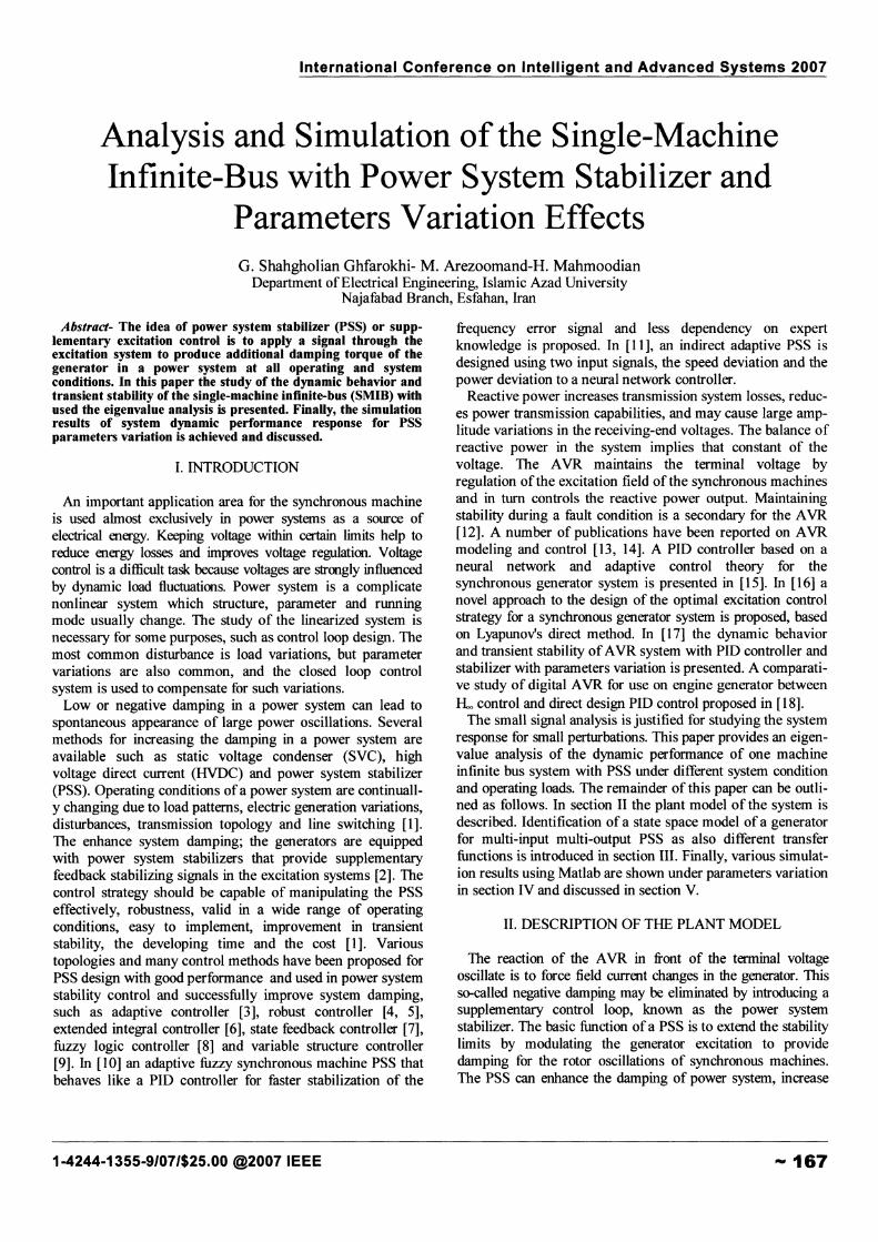
the static stability and improve the transmission capability. ThePSS output is added to the difference between reference andactual value of the terminal voltage. Usual input signal for thePSS are the rotor speed deviations, the accelerating power,active power output or the system frequency. A diagramillustrating the principle mode of operation of a PSS is givenin Fig.1, where the generator speed deviation (L\ror) from thatsynchronous frequency is input signal. The automatic voltageregulator of the generator and the voltage transducer arerepresented by simple first order function GR(s) with the timeconstant TRand the gain K Rand GE( s) with the time constantTE and the gain K E.
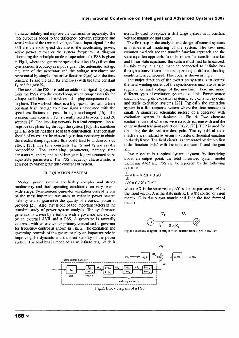
The task ofthe PSS is to add an additional signal Us (outputfrom the PSS) into the control loop, which compensates for thevoltage oscillations and provides a damping component that isin phase. The washout block is a high-pass filter with a timeconstant high enough to allow signals associated with thespeed oscillations to pass through unchanged [16]. Thewashout time constant Tw is usually fixed between 5 and 20seconds [7]. The lead-lag network is a lead compensation toimprove the phase lag through the system [19]. The stabilizergain K p determines the size ofthat contribution. That constantshould of course not be chosen lager than necessary to obtainthe needed damping, since this could lead to undesired sideeffects [20]. The time constants Tw, 't2 and 't4 are usuallyprespecified. The remaining parameters, namely timeconstants 't1 and 't3 and stabilizer gain Kp are assumed to beadjustable parameters. The PSS frequency characteristic isadjusted by varying the time constant of system.
III. EQUATION SYSTEM
Modem power systems are highly complex and strongnonlinearity and their operating conditions can vary over awide range. Synchronous generator excitation control is oneof the most important measures to enhance power systemstability and to guarantee the quality of electrical power itprovides [21]. Also, that is one of the important factors in thetransient study of power system analysis. The synchronousgenerator is driven by a turbine with a governor and excitedby an external AVR and a PSS. A generator is normallyequipped with an exciter for primary control and a governorfor frequency control as shown in Fig. 2. The excitation andgoverning controls of the generator play an important role inimproving the dynamic and transient stability of the powersystem. The load bus is modeled as an infmite bus, which is
normally used to replace a stiff large system with constantvoltage magnitude and angle.
The first step in the analysis and design of control systemsis mathematical modeling of the system. The two mostcommon methods are the transfer function approach and thestate equation approach. In order to use the transfer functionand linear state equations, the system must first be linearized.In this study, a single machine connected to infmite busthrough a transmission line, and operating at different loadingconditions, is considered. The model is shown in Fig.3.
The major function of the excitation systems is to controlthe field winding current of the synchronous machine so as toregulate terminal voltage of the machine. There are manydifferent types of excitation systems available. Power sourceused, including dc excitation systems, ac excitation systemsand static excitation systems [22]. Typically the excitationsystem is a fast response system where the time constant issmall. A simplified schematic picture of a generator withexcitation system is depicted in Fig. 4. Two alternateexcitation control schemes were considered, one with and'theother without transient reduction (TGR) [23]. TGR is used forobtaining the desired transient gain. The cylindrical rotormachine is simulated by seven first order differential equationin the dq frame. The field circuit is represented by simple firstorder function GF(s) with the time constant T3 and the gainK3•
Power system is a typical dynamic system. By linearizingabout an output point, the total linearized system modelincluding AVR and PSS can be represent by the followingequation:d
-LU(=AL\X+BL\UdtL\Y = C~X+D~U
where LU( is the state vector, L\Y is the output vector, ~U isthe input vector, A is the state matrix, B is the control or inputmatrix, C is the output matrix and D is the feed forwardmatrix.
RE+jXEFig.!: Schematic diagram of single machine infinite bus (SMIB) system
power system stabilizer
IIII v,,....------.J: Le~-Lag networks IL J
Fig.2: Block diagram of a PSS
168 ---
International Conference on Intelligent and Advanced Systems 2007
(8)
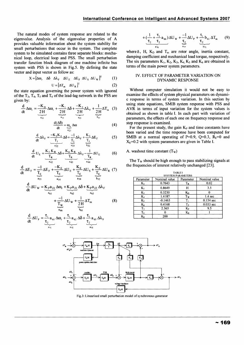
The natural modes of system response are related to theeigenvalue. Analysis of the eigenvalue properties of Aprovides valuable information about the system stability forsmall perturbations that occur in the system. The completesystem to be simulated contains three separate blocks: mechanical loop, electrical loop and PSS. The small perturbationtransfer function block diagram of one machine infmite bussystem with PSS is shown in Fig.5. By defining the statevector and input vector as follow as:
X = [i\oor i\o i\A F i\U E i\E F i\U S i\U W ]T (1)
U=[i\Tm i\UR]T (2)
the state equation governing the power system with ignoredof the T3, T4, Ts and T6 of the lead-lag network in the PSS aregiven by:
~ A r ..... __ -Ko A r ., -K1 s: -K2 ~ 1LlUJI LlUJI + - du + --d""" +-dT (3)
dt r 2H r 2H 2H F 2H m
~ ""'-v--I ~ ~
all al2 an bll
d -1 -K E K E K E-dEF =-dEF +--dU E +-dUs +-dUR (7)dt TE TE TE TE
~ ~ """-v--' """-v--'
ass aS4 aS9 bS2
d-ddUw =K pa 21 dOOr +K pa 21 dO+K p a 23 M F
t '-v---I '-v---I '-v---Ia61 a62 a63
-1 1+-dUW+-dTmTw 2H~ ~
a66 b61
1 't1 -1 'tt+(-+-a 66 )dU w +-dU p +-b 61 dTm (9)
't2 't2 't2 't 2~ ~ '--..r--'
a76 a77 b71
where 0, H, Ko and Tm are rotor angle, inertia constant,damping coefficient and mechanical load torque, respectively.The six parameters K., K 2, K 3, ~, Ks and K 6 are obtained interms of the main power system parameters.
IV. EFFECT OF PARAMETER VARIATION ONDYNAMIC RESPONSE
Without computer simulation it would not be easy toexamine the effects of system physical parameters on dynamic response in terms of system variation. In this section byusing state equations, SMIB system response with PSS andAVR in terms of input variation for the system values isobtained as shown in table I. In each part with variation ofparameters, the effects ofeach one on frequency response andstep response is examined.
For the present study, the gain Kp and time constants havebeen varied and the time response have been computed forSMIB at a normal operating of P=O.9, Q=O.3, ~=O andXE=O.2 with system parameters are given in Table I.
A. washout time constant (Tw)
The Tw should be high enough to pass stabilizing signals atthe frequencies of interest relatively unchanged [23].
TABLE ISYSYTEM PARAMETERS
Parameter Nominal value Parameter Nominal valueK1 0.7643 TR 0.02
K2 0.8649 H 3.5
K3 0.3230 Ko 0Kt 1.4187 Tw 1.4 secKs -0.1463 T1 0.154 sec
~ 0.4168 T2 0.033 secT3 2.365 Kp 9.5TE 0 KR 1KE 200
Fig.3: Linearised small perturbation model of synchronous generator
--- 169
International Conference on Intelligent and Advanced Systems 2007
The roots of characteristic equation for three different valuesof Tware given in table II. Figure 6 shows the step responsefor changing ofTw.
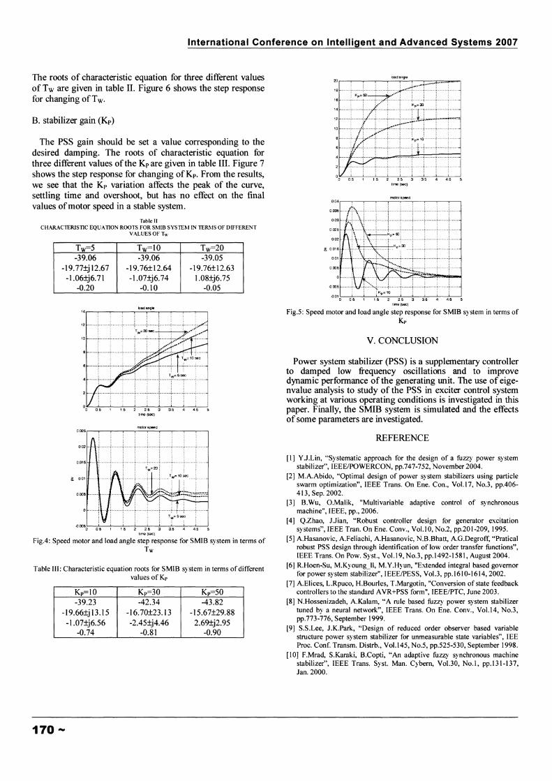
B. stabilizer gain (Kp)
The PSS gain should be set a value corresponding to thedesired damping. The roots of characteristic equation forthree different values of the Kp are given in table III. Figure 7shows the step response for changing ofKp • From the results,we see that the Kp variation affects the peak of the curve,settling time and overshoot, but has no effect on the finalvalues ofmotor speed in a stable system.
Table IICHARACTERISTIC EQUATION ROOTS FOR SMIB SYSTE~f IN TERMS OF DIFFERENT
VALUES OF Tw
Tw=5 Tw=10 Tw=20-39.06 -39.06 -39.05
-19.77±j 12.67 -19.76±12.64 -19.76±12.63-1.06±j6.71 -1.07±j6.74 1.08±j6.75
-0.20 -0.10 -0.05
: :: :::
:: m~~l~~~[~:~r~];t~~i~t!;~~:-": --:--::.-_-_-:::;-T:--I:--J_:::r~I:!o~~---'--__&._..L-____'_______L_ _'_____--L.-----'----'o 0.6 1 1.6 2 2.6 3 3.5 4 45
time (sec)
molorspeed
0.6 1 1.6 2 2.6 3 35 4 4.5 5time (sec)
Fig.4: Speed motor and load angle step response for SMIB system in terms ofTw
Table III: Characteristic equation roots for SMIB system in terms of differentvalues ofKp
Kp=10 Kp=30 Kp=50-39.23 -42.34 -43.82
-19.66±j 13.15 -16.70±23.13 -15.67±29.88-1.07±j6.56 -2.45±j4.46 2.69±j2.95
-0.74 -0.81 -0.90
170 ---
load angle2O,..----.------r----y-,...----r---r-..----r-:-::~~
2 --- -j------1-------l-------j------j------j------i-------t---·--i·----oK..--'----'------<_-'--____'__---'-_.L..--"""O'------l...-----'
o 0.5 1 1 5 2 2.5 3 35 4 4.6 5lime (sec)
motor speed004 ,..-----,-------,------..,.-~--r-____r_-r---,-----,------,
, , , • • I , , •
a 0.015
{lOO6!------ -~--\-I- - ~--- -~ .. - - - - --~ - - - .. --~- -----~- --.- .~-------~--.. -. -~-- - ---i
{l01 L..--~---'--__&.______'______'_L_ _'_____--J........---'------'
o 0.5 1 1.6 2 25 3 36 4 4.6 5time (sec)
Fig.5: Speed motor and load angle step response for SMIB system in terms ofKp
v. CONCLUSION
Power system stabilizer (PSS) is a supplementary controllerto damped low frequency oscillations and to improvedynamic performance of the generating Wlit. The use of eigenvalue analysis to study of the PSS in exciter control systemworking at various operating conditions is investigated in thispaper. Finally, the SMIB system is simulated and the effectsof some parameters are investigated.
REFERENCE
[1] Y.J.Lin, "Systematic approach for the design of a fuzzy power systemstabilizer", IEEE/POWERCON, pp.747-752, November 2004.
[2] M.A.Abido, "Optimal design of power system stabilizers using particleswarm optimization", IEEE Trans. On Ene. Con., VoL17, No.3, pp.406413, Sep. 2002.
[3] B.Wu, O.Malik, "Multivariable adaptive control of synchronousmachine", IEEE, pp., 2006.
[4] Q.Zhao, J.Jian, "Robust controller design for generator excitationsystems", IEEE Tran. On Ene. Conv., VoLI0, No.2, pp.201-209, 1995.
[5] A.Hasanovic, A.Feliachi, A.Hasanovic, N.B.Bhatt, A.a.Degroff, "Praticalrobust PSS design through identification of low order transfer functions",IEEE Trans. On Pow. Syst., Vo1.19, No.3, pp.1492-1581, August 2004.
[6] R.Hoen-Su, M.Kyoung_lI, M.Y.Hyun, "Extended integral based governorfor power system stabilizer", IEEEIPESS, Vo1.3, pp.1610-1614, 2002.
[7] A.Elices, L.Rpuco, H.Bourles, T.Margotin, "Conversion of state feedbackcontrollers to the standard AVR+PSS form", IEEE/PTC, June 2003.
[8] N.Hossenizadeh, A.Kalam, "A rule based fuzzy power system stabilizertuned by a neural network", IEEE Trans. On Ene. Conv., Vo1.14, No.3,pp.773-776, September 1999.
[9] S.S.Lee, J.K.Park, "Design of reduced order observer based variablestructure power system stabilizer for unmeasurable state variables", lEEProc. Conf. Transm. Distrb., VoL145, No.5, pp.525-530, September 1998.
[10] F.Mrad, S.Karaki, B.Copti, "An adaptive fuzzy synchronous machinestabilizer", IEEE Trans. Syst. Man. Cybern, Vo1.30, No.1, pp.131-137,Jan. 2000.
International Conference on Intelligent and Advanced Systems 2007
[II] P.Shamsollahi, O.P.Malik, "Adaptive control applied to synchronousgenerator", IEEE Trans. On Ene. Conv., VoLI4, No.4, pp.l341-1346,1999.
[12] L.Ren, G.W.Irwin, D.Flynn, "Nonlinear identification and control of aturbogenerator - An on-line scheduled multiple model/controllerapproach", IEEE Trans. On Ener. Conv., VoL20, No.1, pp.237-245,March 2005.
[13] D.Flynn, B.W.Hogg, E.Swidenbank, KJ.Zachariah, "A self tuningautomatic voltage regulator designed for an inductrial environment",IEEE Trans. On Ene. Conv., VoLll, No.2, pp.429-434, June 1996.
[14] M.G.M.Ardle, DJ.Morrow, P.A.Calvert, O.Cadel, "A fuzzy tuning PIDautomatic voltage regulator for small salient poles alternative",IEEE/ICPST, VoLI, pp.103-108, December 2000.
[15] WJun, G.Zhang, "The adaptive PID controller based on neural networkfor the synchronous generator excitation system", IEEEIIPEMC, VoL2,pp.681-683, August 2004.
[16] J.Machowski, J.W.Bialek, S.Robak, J.R.Bumby, "Excitation controlsystem for use with synchronous generators", lEE Proc. Tran. Dist.,VoL145, No.5, pp.537-546, September 1998.
[17] J. Faiz, Gh. Shahgholian, M.Arezoomand, "Analysis and simulation ofthe AVR system and parameters variation effects", IEEEIPOWRENG,450-453, April 2007.
[18] M.Asama, H.Ukai, M.Sone, K.Nakamura, "Comparative studies ofdigital AVR for use on engine generator between Hoo control and directdesign PID control", IEEE/PCC, VoLl, pp.211-214, April 2002.
[19] Y.L.Abdel, M.A.Abido, A.H.Mantawy, "Robust tuning of power systemstabilizer in multimachine power systems", IEEE Trans. On Pow. Sys.,VoLI5, No.2, pp.735-740, May 2000.
[20] P.Kundur, "Power system stability and control", McGraw-Hili, 1994.[21] J.Wen, S.Cheng, O.P.Malik, "A synchronous generator fuzzy excitation
controller optimally desined with a genetic algorithm", IEEE, pp.l06-111,1997.
[22] X.C.Zhang, G.H.Cheng, Z.Xu, "User defined excitation system modelsfor power system stability analysis in PSASP", IEEE/PES, pp.I-5, 2005.
[23] K.Bhattacharya, J.Nanda, M.L.Kothari, "Optimization and performanceanalysis of conventional power system stabilizers", Elec. Pow. & Ene.Syst., Vol. 19, No.7, pp.449-458, 1997.
-- 171