analysis objectives - lisafea.com · based on a nominal weight of 150 lbf/ft3, the self-weight of...
TRANSCRIPT

Analysis Objectives The objective of this analysis is to determine whether structural bracing is required to support a concrete parking garage ramp under the weight of a large piece of equipment that must transverse the ramp to reach the installation location. The determining criteria will be the maximum deflection of the slab under the applied loading from the equipment. The maximum permitted deflection shall be the span length
divided by 500 ( ).
The analysis compares the deflections under the equipment load to the deflections under the specified design loads as an additional verification.
Reference Documents Structural Drawing Package, Dated October 29, 2010- including Bulletin 4, Hickok Cole
Architects: NPR 1111 North Capitol Street Washington DC 20002
CenTraVac Isolator Selection WCU-1 worksheet
Centrifugal Water Chiller Equipment Submittal, Dated August 17, 2011
ACI 318- Building Code Requirements for Structural Concrete. American Concrete Institute.
Problem Description JCM Associates is a mechanical contractor installing equipment in a facility for NPR. A centrifugal water chiller will be delivered to Level 01 of the parking garage and then will be transported on rollers across Level 01 and down the ramp to Level P1, where it will be installed.
The ramp is designed as a 9.5” thick doubly reinforced one way slab. The concrete has a specified minimum compressive strength (f’c) of 5,000 psi. Reinforcement consists of #6 top bars at 12” on center and #6 bottom bars at 9” on center. Reinforcing steel is ASTM A615 Grade 60 (Fy 60 ksi). Reinforcing bars (#6) are provided perpendicular to the span at 18” on center. Dimensions of the slab are taken from the project plans as a 24’ span and a 70’ long ramp.
The Centrifugal Water Chiller has a shipping weight of 17,634lb and an operational weight of 19,793lb. For the basis of this analysis, the transportation loads are conservatively assumed to be the operational weight plus 10%, distributed to the nearest transport skate directly.
This report summarizes the results of a Finite Element Analysis (FEA) of the chiller transport loads on the slab. This analysis models the slab as a linear elastic material with a Modulus of Elasticity of 4x10⁶psi, Poisson Ratio of 0.2, and a density of 150lbf/ft3. The edges of the slab are modeled as simply supported. The slope of the ramp is neglected. The FEA model is composed of twenty node hexahedron (hex20) elements (see Figure 1).

Figure 1- Model Development Chiller and Ramp (top), Loads and Dimensions (middle), FEA Model (bottom)
Analysis Procedures and Results
Model Development and Verification An initial model of a beam was developed to comply with the ACI design procedure for a one way slab. The slab is modeled as a beam 1ft wide and 9.5” thick. The ends are simply supported and the beam is considered to be an isotropic linearly elastic material. The Modulus of Elasticity of the slab is taken as
57,000 ′ ~ 4 x 10⁶psi
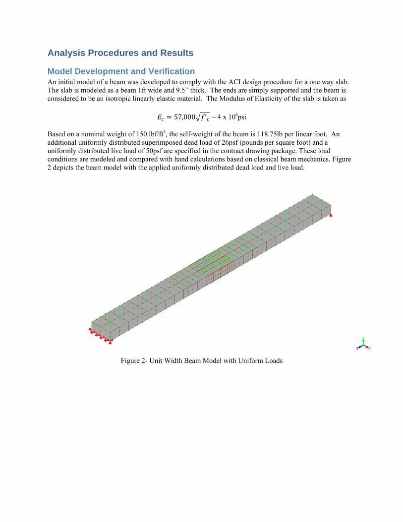
Based on a nominal weight of 150 lbf/ft3, the self-weight of the beam is 118.75lb per linear foot. An additional uniformly distributed superimposed dead load of 26psf (pounds per square foot) and a uniformly distributed live load of 50psf are specified in the contract drawing package. These load conditions are modeled and compared with hand calculations based on classical beam mechanics. Figure 2 depicts the beam model with the applied uniformly distributed dead load and live load.
Figure 2- Unit Width Beam Model with Uniform Loads
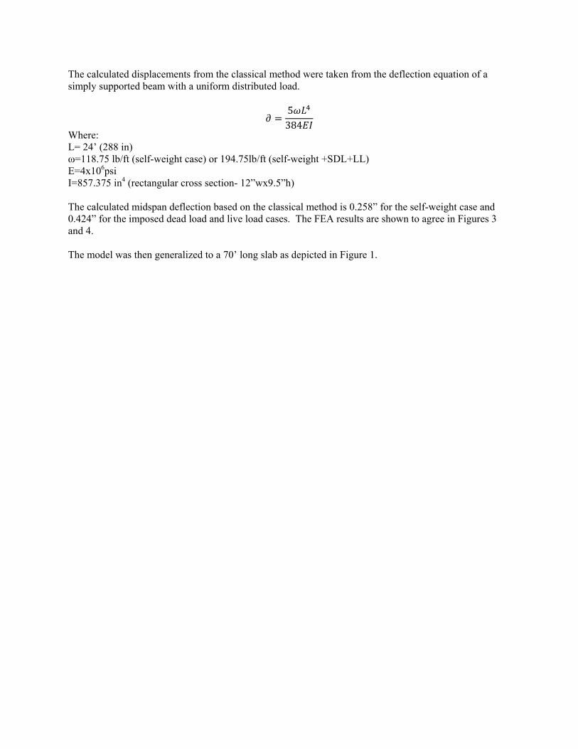
The calculated displacements from the classical method were taken from the deflection equation of a simply supported beam with a uniform distributed load.
5384
Where: L= 24’ (288 in) ω=118.75 lb/ft (self-weight case) or 194.75lb/ft (self-weight +SDL+LL) E=4x10⁶psi I=857.375 in4 (rectangular cross section- 12”wx9.5”h) The calculated midspan deflection based on the classical method is 0.258” for the self-weight case and 0.424” for the imposed dead load and live load cases. The FEA results are shown to agree in Figures 3 and 4. The model was then generalized to a 70’ long slab as depicted in Figure 1.
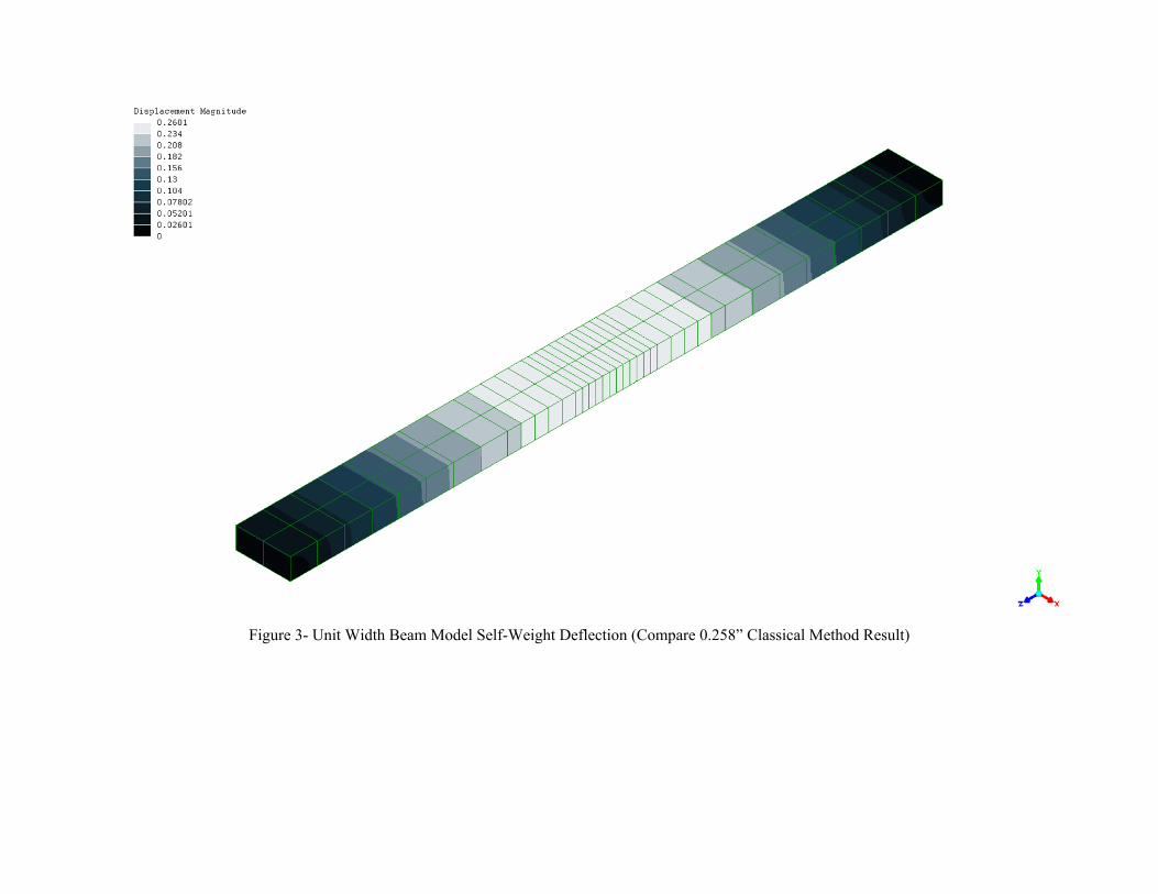
Figure 3- Unit Width Beam Model Self-Weight Deflection (Compare 0.258” Classical Method Result)
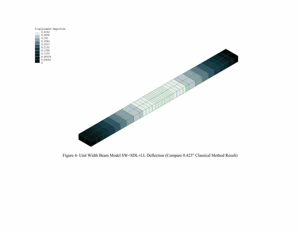
Figure 4- Unit Width Beam Model SW+SDL+LL Deflection (Compare 0.423” Classical Method Result)

One Way Slab Load Case The resultant force of the concentrated loads from the chiller transport rollers is applied at the mid span of the slab. Based on the assumption of a one way slab, the deflection is independent of the placement of the loads along the length of the slab. The maximum deflection under the chiller is seen to be 0.329” in Figure 5. This value falls midway between the model verification deflections calculated and is under the deflection limit criteria of this analysis (L/500 = 0.576”). This indicates that the transport of the chiller across the slab is within the design parameters of the structure and does not require reinforcement of the ramp.
Two Way Slab Case While the parking garage ramp in not specifically designed as a two way slab, the influence of the transitions to and from the ramp lend appreciable stiffness to the edges and limit the applicability of the one way slab model as the chiller enters or exists the ramp. In this case, the boundary conditions of a simply supported beam are modified with the addition of constraints along the entrance and exit edge of the ramp. The net effect of this is to limit the maximum deflection to approximately 0.3” while the chiller is in the middle of the ramp (Figure 6) and indicates that the transition from the parking level to the floor presents no need for reinforcement (Figure 7).
Summary Remarks It should be noted that this analysis is an appreciably simplified approximation of the actual conditions. The calculated deflections should not be taken in absolute terms, but rather used as a relative measure of the load imparted by the equipment transport to that of the load the designers anticipated. The assumptions made in the material properties are conservative and underestimate the true strength and stiffness of the structure. Regardless of the calculations, care and prudence should be exercised in the execution of the equipment transport. Should jacking of the load be required in order to adjust the roller positions on the ramp, I recommend that you use two jacks to distribute the load across the face of the slab to the maximum extent practical. Making an effort to avoid the midspan of the slab will help to reduce the loads the ramp must resist. This analysis assumes that the transport is slow and neglects impact loads and dynamic effects.

Figure 5- One Way Slab Model, Deflection Under Chiller Transport ( limit = 0.576” )

Figure 6- Two Way Slab Model, Deflection Under Chiller Transport- chiller mid span ( limit = 0.576” )
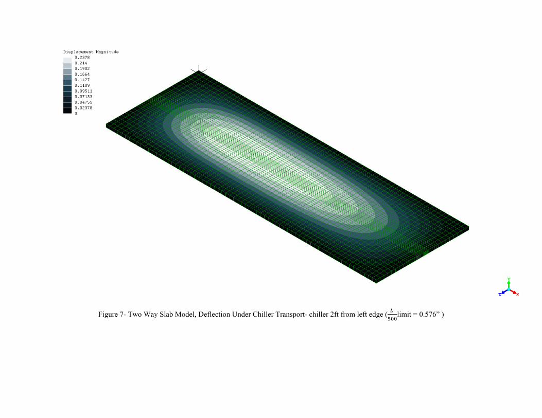
Figure 7- Two Way Slab Model, Deflection Under Chiller Transport- chiller 2ft from left edge (
limit = 0.576” )
Professional Engineering & Technical Services
Zuhowski Engineering, LLC can provide you
with the technical skills and support needed
to succeed in the world of ever increasing
technology and regulation. We understand
the influence of the competing priorities,
resource constraints, and various degrees of
problem definition you face.
Support from beginning to end
Zuhowski Engineering is committed to provid-
ing you the best service, delivered to your
requirements. We would like the opportunity
to serve you and we want to be your pre-
ferred source of engineering and technical
services. Please visit our website at your con-
venience for some additional information
about us, or simply contact me at the tele-
phone number or address below. I look for-
ward to speaking with you.
Michael Zuhowski, PE
President
Safe and Economical Solutions
Zuhowski Engineering, LLC
82 Chautaugua Road
Arnold, MD 21012
Phone: 443- 254- 8661
E-mail: [email protected]
www.zuhowski.com

Industrial Solutions
From initial conception through
fabrication, erection, commissioning and
operation, we provide the expertise
necessary for your fluid handling
challenges .
Process & Piping Services
Conceptual Design, Cost, & Feasibility Studies
Equipment Sizing, Specifications & Layout
Process & Utility Piping Systems
Pipe Stress Analysis
Plumbing
HVAC
Industrial Ventilation
Tank & Pressure Vessel Design
Process Flow Diagrams (PFDs)
Energy & Material Flow Balances
Dust Collection & Fume Removal
Piping & Instrument Diagrams (P&IDs)
Fast Answers to Pressing Problems
Facilities Engineering
Restoration or repairs can be an expensive,
inconvenient and potentially controversial
process for building owners. We can help
you plan, organize, staff, and direct to
produce what is agreed upon, within the
constraints imposed.
Facilities Engineering Services
Site Plans
M/E/P Services
Special Structures
HVAC & Refrigeration
Commercial Kitchens & Laundries
Space Planning & Tenant Fit Outs
Process & Supplier Quality
Zuhowski Engineering represents the customer’s
interests from design through delivery- on time
and on budget-by verifying designs and controlling
fabrication processes & components.
From the initial identification and qualification of
suppliers to the creation and maintenance of
Approved Vendor Lists, Zuhowski Engineering
assures successful hardware design and fabrication.
Knowing that quality cannot be inspected into a
product, we drive each phase of the procurement
and fabrication processes.
At Zuhowski Engineering, Quality means more than
conformance to specification, we are committed to
maintaining your schedule and budget.
Sourcing & Supplier Quality Services
Capture, Containment, & Rescue of Defects
In -Process Verifications
Joint Quality Planning
Process Validations
Pre-Award Surveys
Test Witnessing