analysis of a delta like parallel mechanism with an ... · analysis of a delta like parallel...
TRANSCRIPT

The 14th IFToMM World Congress, Taipei, Taiwan, October 25-30, 2015
DOI Number: 10.6567/IFToMM.14TH.WC.OS2.032
Analysis of a Delta Like Parallel Mechanismwith an Overconstrained Serial Chain as Platform
M. Pfurner∗
University of InnsbruckInnsbruck, Austria
Abstract— This article shows a new type of parallelmechanism with a configurable platform. New in this con-text is that the platform is not a rigid body, it is formed by aclosed overconstrained serial chain. This gives the oppor-tunity to change the geometry of the platform and thereforethe relative position of the anchor points of the legs. In thispaper a special type of these parallel mechanisms is ana-lyzed. It is based on the famous Delta robot, but the rigidplatform is replaced by Bricard’s orthogonal 6R-linkage.Herein the direct kinematics of this special new parallelmechanism with an additional degree of freedom in the plat-form is solved and the impact of the additional freedom onthe motion of the platform is shown.
Keywords: parallel mechanism, configurable platform, overcon-strained mechanism, Delta robot, Bricard orthogonal chain
I. IntroductionEvery year a relatively large amount of articles are pub-
lished on topics related to parallel mechanisms. In principlea parallel mechanism consists of two rigid bodies, a baseand a platform, connected via some legs. In most casesthese legs are serial chains all of the same type. It is notpossible to give a short overview on the developments ofthis field. A very good book with an extensive overviewdedicated solely to parallel robots is [1].
On the other hand there is a very small number of ar-ticles published concerning parallel robots with a config-urable platform. To the best of the authors knowledge onlyin [2] a spatial overconstrained serial chain is used as plat-form. Others [3], [4], [5], [6], [7] use planar serial n-Rchains as configurable platforms, where R stands for revo-lute joints and n = 4 or 8, respectively. All of them usetheir legs to configure the platform geometry.
This article deals with a new type of parallel mechanism.It is based on the Delta robot presented in [8] but the rigidplatform is replaced by an overconstrained Bricard orthog-onal chain [9]. Using this serial closed 6R-chain with anadditional motor one may change the relative position of theanchor points of the legs on the platform. One reason forusing this closed loop is, that the input-output of this chainare relatively easy to handle in computations and thereforemany of the equations can be printed in this publication. Ofcourse in this construction any overconstrained serial closed
∗E-mail: [email protected]
loop chain could be used instead of the one used herein.It is known by the author that a great drawback of this
type of mechanism is that it adds the inertia of an additionalmotor to the end-effector. On the other hand this additionaldegree of freedom can be used to overcome singularities bychanging the platform geometry or as a kind of gripper.
The use of the Delta robot together with Bricard’s orthog-onal closed loop chain is no limitation on the theory but hasthe only reason, that using parts of these mechanisms manyof the equations can be printed in this paper. Otherwise theysoon get very complicated and could only be shown in syn-thetic form, which has to be done at the end of this articleas well.
The article is organized as follows. Section II gives ashort overview on the analysis of mechanisms using kine-matic mapping while Section III concentrates on the serialchains used as legs of the herein described parallel mech-anism. In Section IV the analysis of the overconstrainedmechanism used as a platform is described and Section Vcombines all the former Sections and analyses the parallelmechanism with a configurable platform. The impact of theadditional degree of freedom of the platform on its motionis shown in Section VI. Finally Section VII gives conclu-sions and an outlook to future work.
II. Algebraic Analysis of MechanismsIn this paper mechanisms will be analyzed using kine-
matic mapping, which maps a Euclidean transformationonto a point in the seven dimensional kinematic imagespace P 7. This mapping can be described by using theparameterization of the 4x4 matrix operator of the trans-formation that reads
T =
(1 0t A
)(1)
with the translational part of the transformation is
t =
2x0y1 − 2y0x1 − 2y2x3 + 2y3x2,2x0y2 − 2y0x2 − 2y3x1 + 2y1x3,2x0y3 − 2y0x3 − 2y1x2 + 2y2x1.
(2)
and the rotational part is given by
A =[x20+x2
1−x23−x2
2 −2x0x3 + 2x2x1 2x3x1 + 2x0x2
2x2x1 + 2x0x3 x20+x2
2−x21−x2
3 −2x0x1 + 2x3x2
−2x0x2 + 2x3x1 2x3x2 + 2x0x1 x20+x2
3−x22−x2
1
](3)

The parameters (x0 : x1 : x2 : x3 : y0 : y1 : y2 : y3) canbe seen as coordinates in P 7 and are the so called Study pa-rameters which are very closely related to dual quaternions.Mappings of Euclidean displacements lie on the so calledStudy quadric
x0y0 + x1y1 + x2y2 + x3y3 = 0. (4)
In this article we will use normalized dual quaternions thatadditionally fulfill the condition
x20 + x21 + x22 + x23 − 1 = 0. (5)
Throughout the paper both representations will be used, de-pending on which is more convenient at that time whilecomputations were done in P 7 only.
Kinematic mapping can be used to map the end-effectormotion of a mechanism onto a point, curve or variety in theseven dimensional kinematic image space P 7, dependingon the degrees of freedom of the mechanism.
In case of serial manipulators the forward kinematicsyields a parametric representation r of the motion of theend-effector in this space. To use all the advantages of al-gebraic geometry the aim of this analysis is to find algebraicequations that describe manifolds in P 7 with an intersectionthat is equal to r. Those equations can be used in solvingthe inverse kinematics.
To achieve implicit equations intersecting in the paramet-ric representation the algorithm described in [10] is used.It searches for implicit equations of defined degree in thekinematic image space that have the property, that the r ful-fills this equation.
If it is possible to find such equations in P 7 they describethe so called constraint manifolds of the serial chains. Inother words intersections of these manifolds yield, via theinverse kinematic mapping, all possible poses (position andorientation) the end-effector of the serial chain can reach.For a deeper introduction to algebraic analysis of serial ma-nipulators using kinematic mapping the reader is referredto [11].
In the analysis of parallel manipulators the constraintmanifolds of the legs can be used. Each leg manipulates itsend-effector coordinate frame in the platform with respectto the fixed coordinate frame in the base. If for all legs thebase frames coincide and the end-effector frames can fulfilla common motion, then they can be mounted together andthey can perform a common motion. Therefore the motionof the platform has to lie in the intersection of all constraintmanifolds of the legs.
Throughout the whole paper the design of the mecha-nisms will be given in Denavit-Hartenberg (DH) conven-tions. Because of algebraic computational reasons for allangles the tangent half angle substitution will be used inthe computations. That means that instead of an angle uthe algebraic value v = tan (u/2) is used. Using this re-
parameterization the identities
sin(u) =2v
1 + v2, cos(u) =
1− v2
1 + v2(6)
can be used to transform equations with trigonometric func-tions to algebraic equations. In the paper for better under-standing most of the angles will be given in degrees.
III. Analysis of the LegsFirst of all we will analyze the geometry of the legs of
the parallel mechanism. The author wants to mention thatit would be possible to use different kinds of legs, whichwould result in more complicated equations that could notbe displayed in this paper any more.
Because of the fact, that in this case all legs are equalwe will analyze one in a canonical position to get the con-straint manifolds. In this special position it is possible toderive them in a fully arbitrary way, i.e., without specify-ing the design. After this analysis the leg is mounted to thebase and platform by applying coordinate transformationsin the base and the end-effector frame, respectively. Onebig advantage of kinematic mapping is, that these transfor-mations in Euclidean 3-space can also be applied as lineartransformations to the constraint manifolds in the kinematicimage space. Therefore it is always possible to analyze se-rial chains in a canonical pose and to transform it later onto an arbitrary position in space.
A. Analysis of a Canonical LegA canonical pose of the leg is given when the first axis
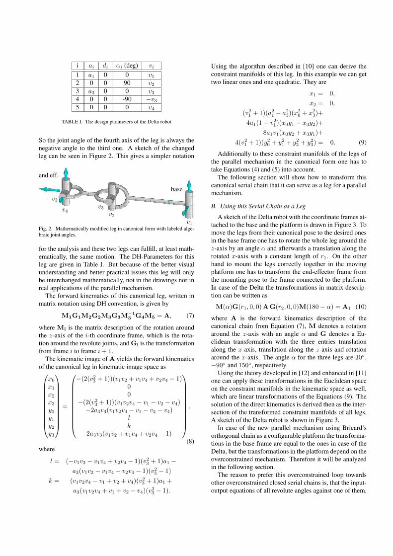
coincides with the z-axis of the base frame and the footpoint of the common normal of first and second joint axesis the origin of the base frame. Furthermore in the home po-sition all axes are parallel to the yz-plane of the base frame.Additionally the z-axis of the end-effector coincides withthe last joint axis and the origin is located at the foot pointof the common normal of the last and last but one revolutejoint. A sketch of the leg for the analyzed parallel mecha-nism is shown in Figure 1.
Fig. 1. Leg of the parallel mechanism in canonical form.
In this article we will model the parallelogram of theleg in a different way. The reason is that we use Denavit-Hartenberg convention and there it is inconvenient to han-dle. The parallelogram is interchanged by a 2R chain,where the second rotation is negative equal to the first one.
i ai di αi (deg) vi
1 a1 0 0 v12 0 0 90 v23 a3 0 0 v34 0 0 -90 −v35 0 0 0 v4
TABLE I. The design parameters of the Delta robot
So the joint angle of the fourth axis of the leg is always thenegative angle to the third one. A sketch of the changedleg can be seen in Figure 2. This gives a simpler notation
v1
v2
v3
−v3v4
base
end eff.
Fig. 2. Mathematically modified leg in canonical form with labeled alge-braic joint angles.
for the analysis and these two legs can fulfill, at least math-ematically, the same motion. The DH-Parameters for thisleg are given in Table I. But because of the better visualunderstanding and better practical issues this leg will onlybe interchanged mathematically, not in the drawings nor inreal applications of the parallel mechanism.
The forward kinematics of this canonical leg, written inmatrix notation using DH convention, is given by
M1G1M2G2M3G3M−13 G4M5 = A, (7)
where Mi is the matrix description of the rotation aroundthe z-axis of the i-th coordinate frame, which is the rota-tion around the revolute joints, and Gi is the transformationfrom frame i to frame i+ 1.
The kinematic image of A yields the forward kinematicsof the canonical leg in kinematic image space as
x0x1x2x3y0y1y2y3
=
−(2(v23 + 1))(v1v2 + v1v4 + v2v4 − 1)00
−(2(v23 + 1))(v1v2v4 − v1 − v2 − v4)−2a3v3(v1v2v4 − v1 − v2 − v4)
lk
2a3v3(v1v2 + v1v4 + v2v4 − 1)
,
(8)where
l = (−v1v2 − v1v4 + v2v4 − 1)(v23 + 1)a1 −a3(v1v2 − v1v4 − v2v4 − 1)(v23 − 1)
k = (v1v2v4 − v1 + v2 + v4)(v23 + 1)a1 +
a3(v1v2v4 + v1 + v2 − v4)(v23 − 1).
Using the algorithm described in [10] one can derive theconstraint manifolds of this leg. In this example we can gettwo linear ones and one quadratic. They are
x1 = 0,
x2 = 0,
(v21 + 1)(a21 − a23)(x20 + x23)+
4a1(1− v21)(x0y1 − x3y2)+8a1v1(x0y2 + x3y1)+
4(v21 + 1)(y20 + y21 + y22 + y23) = 0. (9)
Additionally to these constraint manifolds of the legs ofthe parallel mechanism in the canonical form one has totake Equations (4) and (5) into account.
The following section will show how to transform thiscanonical serial chain that it can serve as a leg for a parallelmechanism.
B. Using this Serial Chain as a Leg
A sketch of the Delta robot with the coordinate frames at-tached to the base and the platform is drawn in Figure 3. Tomove the legs from their canonical pose to the desired onesin the base frame one has to rotate the whole leg around thez-axis by an angle α and afterwards a translation along therotated x-axis with a constant length of r1. On the otherhand to mount the legs correctly together in the movingplatform one has to transform the end-effector frame fromthe mounting pose to the frame connected to the platform.In case of the Delta the transformations in matrix descrip-tion can be written as
M(α)G(r1, 0, 0)AG(r2, 0, 0)M(180− α) = A1 (10)
where A is the forward kinematics description of thecanonical chain from Equation (7), M denotes a rotationaround the z-axis with an angle α and G denotes a Eu-clidean transformation with the three entries translationalong the x-axis, translation along the z-axis and rotationaround the x-axis. The angle α for the three legs are 30◦,−90◦ and 150◦, respectively.
Using the theory developed in [12] and enhanced in [11]one can apply these transformations in the Euclidean spaceon the constraint manifolds in the kinematic space as well,which are linear transformations of the Equations (9). Thesolution of the direct kinematics is derived then as the inter-section of the transformed constraint manifolds of all legs.A sketch of the Delta robot is shown in Figure 3.
In case of the new parallel mechanism using Bricard’sorthogonal chain as a configurable platform the transforma-tions in the base frame are equal to the ones in case of theDelta, but the transformations in the platform depend on theoverconstrained mechanism. Therefore it will be analyzedin the following section.
The reason to prefer this overconstrained loop towardsother overconstrained closed serial chains is, that the input-output equations of all revolute angles against one of them,

Fig. 3. A sketch of the delta robot.
i ai di αi (deg) vi
1 a1 0 90 v12 a2 0 90 v23 a3 0 90 v34 a4 0 90 v45 a5 0 90 v56 a6 0 -90 v6
TABLE II. The design parameters of the Bricard orthogonal chain
the motor, are relatively short. This gives the possibility toshow some of the results in this publication, although it getsquite complicated soon.
It has to be mentioned that any of the known overcon-strained mechanisms could be used as platform.
IV. Analysis of the Overconstrained MechanismBricard orthogonal chain is an overconstrained 6R-chain
described in [9] and extensively studied in [13]. The DH-Parameters of this linkage are given in Table II with theadditional equation
a21 − a22 + a23 − a24 + a25 − a26 = 0 (11)
In this paper we use the simplification that all ai areequal. This is to keep symmetry in the resulting parallelmechanism. Computation of the input-output equations isstraightforward by computing the inverse kinematics of theserial chain using the algorithm described in [12], where theend-effector is restricted to coincide with the base frame. In
the tangent half of the joint angles these equations are
v1 = −v3, v5 = v1
v4 = −v2, v6 = v2 (12)v21v
22 + v21 + v22 − 3 = 0
To keep the symmetry in the analysis while using this mech-anism as a configurable platform we do not analyze the mo-tion of the mechanism with respect to the standard coordi-nate frame Fs (see smaller frame in Fig. 4). This is definedin a way, where the origin lies in on the foot point of thecommon normal of axes one an two on the first axes , thez-axis is aligned with the first revolute axis and the x-axiscoincides with the common normal of first and last axis,as shown in [14]. In this frame the last link is fixed an allthe other move with respect to the input parameter of theoverconstrained linkage. This would give one link a spe-cial importance and gives an asymmetrical configuration.Therefore we want to change this base frame to a symmet-rical one.
The frame F that forms the base in this case is definedas follows: The origin is the barycenter B of the triangleformed by the foot points of the common normals of axes1, 3 and 5, here denoted by P1, P3, and P5, with the adja-cent axes. The z-axis is perpendicular to this plane and thex-axis is parallel to the Vector
−−−→P5P3, as labeled in Fig. 4.
Note that in this frame none of the links of the overcon-strained mechanism is fixed. In Fs the barycenterB has thecoordinates
B =1
3
−v21v1
(v21 + 1)v2
. (13)
The normal vector of the plane of the triangle is
−→n =1
2(v21 + 1)
v1v2v2v1
. (14)
Of course to achieve B and −→n depending on the input pa-rameter of the linkage only, here for example v1, one has tokeep Equations (12) into account. For a shorter descriptionthis is omitted.
The distance from B to Pi is equal to
d =1
3
√3(v21 + 1) (15)
and the tangent half of the angle between ~n and the xy-plane of the base frame is
t =
√−√3v1 − 3√3v1 + 3
. (16)
In both Equations (15) and (16) the last equation in (12)was used for simplification and to achieve these values in

dependence on the input parameter of the overconstrainedmechanism v1, that correspond to the first joint angle. Thevalues d and t are crucial to compute the transformationsneeded in the end-effector frames of the legs in the nextsection.
Some configurations of the Bricard orthogonal frame aredrawn in Figures 4– 7 together with the new base coordi-nate frame F . As one can see this linkage has two planar
FS
F
P1
P3
P5
Fig. 4. Bricard orthogonal chain to an input angle of 0◦
Fig. 5. Bricard orthogonal chain to an input angle of 30◦
configurations to the input parameter v1 corresponding tothe angles 0◦, see Figure 4, and 120◦, see Figure 8. An-other interesting configuration is the one that correspondsto the input of 90◦. It is shown in Figure 7 and here all thecommon normals lie on the edges of a cube.
V. Analysis of the Parallel MechanismNow we will use this analysis for the coordinate transfor-
mation of the end-effector frame of each leg to the commonframe in the configurable platform, which will be the frame
Fig. 6. Bricard orthogonal chain to an input angle of 60◦
Fig. 7. Bricard orthogonal chain to an input angle of 90◦
F . The transformation from the end-effector frame of themounted leg in the base, described in Section III-B to thecommon frame in the platform is given (in DH conventionseen from the coordinate frame attached to the last axis ofthe leg) by a translation in the direction of the x-axis witha length r2, then a rotation around the z-axis with the an-gle corresponding to t, afterwards a translation along thex-axis by d and a rotation of 90◦ around the same axis andat the end a rotation around the z-axis by an angle α. Inmatrix description this transformation in the end-effectorframe reads
G(r2, 0, 0)M(t)G(d, 0, 90◦)M(α) = T, (17)
where α is 150◦, −90◦ and 30◦ for the three legs, respec-tively.
The translation with length r2 is not crucial but it is givesthe opportunity, that the mounting points of the overcon-strained mechanism are not directly on the last axis of thelegs.

Fig. 8. A Delta robot with a Bricard orthogonal chain as platform.
The connection of the legs with the overconstrainedmechanism is done using a revolute joint that coincides withjoints 1, 3 and 5 of the Bricard linkage. In Figure 8 the plat-form is in the second planar configuration (the first one isshown in Figure 4) that occurs to the input angle of 120◦.
The next step is to apply all the transformations in thebase and the end-effector frames on the constraint mani-fold of the canonical legs in kinematic image space, givenby Equations (9). This yields a system of three non-linear equations in the coordinates of the image space(x0, x1, x2, x3, y0, y1, y2, y3) for each leg.
Furthermore these equations depend on the input param-eter of the overconstrained platform and the joint parame-ters of the first axes of the legs, which are used as the param-eters for the motors. This gives in common nine nonlinearequations that have to be fulfilled simultaneously and ad-ditionally Equation (4) and Equation (5) coming from thestructure of the kinematic image space. A Groebner basisof the transformed constraint manifolds of each leg give thethree systems of equations
x3 = 0, x2 = 0, gl1 = 0 (18)x3 = 0, 3x1 +
√3x2 = 0, gl2 = 0 (19)
x3 = 0, 3x1 −√3x2 = 0, gl3 = 0 (20)
where gli, i = 1, . . . , 3, are quadratic equations in the co-ordinates of the image space. By using these equations to-gether with Equation (4) and Equation (5) one can easilysee that a part of the solution is
x0 = 1, x1 = 0, x2 = 0, x3 = 0, y0 = 0. (21)
Therefore this new mechanism is, like the Delta, able to
perform translations of the platform with respect to the basonly.
Substitution of these values into the remaining threeequations gli, i = 1, . . . , 3, yields three quadratic equationsin the remaining unknowns y1, y2 and y3 depending on thethree input parameters of the legs and the input parameterof the overconstrained mechanism. A closer look on theseequations show that the quadratic terms of these equationsare of the type ci(y21 + y22 + y23), i = 1, . . . , 3. Thereforeone can use linear combinations to get rid of the quadraticterms in two of the three equations. Then this system ofequations has the form
g10(y21 + y22 + y23) + g12y2 + g13y3 + g14 = 0
g21y1 + g22y2 + g23y3 + g24 = 0
g31y1 + g32y2 + g33y3 + g34 = 0 (22)
with coefficients gij depending on all the input parameters.This system of equations can be solved for y1, y2 and y3and gives two triples of solutions. These are exactly the so-lutions for the direct kinematics of this new type of parallelmechanism, but they are far too long to be displayed here.Note that no design of the legs is used until this point.
VI. Using the Additional Freedom of the PlatformThis Section deals with the extra degree of freedom of
the platform using an example. Here the length of the linksin the legs (see Table I) are given as
a1 = 3, a3 = 5, r1 = 2, r2 = 0.5 (23)
and the common length of all links of the overconstrainedlinkage are set equal to one.
From the previous Section V we know the solution of thedirect kinematics as
x0 = 1, y0 = 0
xi = 0, yi = fi(m1,m2,m3, v1), i = 1, . . . , 3 (24)
where fi are functions depending on the input parametersof the three legs mi and the one coming from the overcon-strained mechanism v1. In case of a symmetrical configura-tion with all leg parameters equal to 3
5 these equations looklike
y3 = − 1
12
√√3− v1√3 + v1
√3v1 −
1
4
√√3− v1√3 + v1
− 45
34±
1
204√√
3 + v1
√−(−20196
√3(v21 + 1)v1+
1156√3√
3(v21 + 1)v21 − 171024v1 − 7497√3v21
+4335v31 − 23664√3√
3(v21 + 1)− 135528√3)
y2 = y1 = 0. (25)
This configuration means that the impact of the addi-tional degree of freedom only yields a translation of theorigin of the moving frame in the z-direction of the mecha-nism. This is also shown in Figure VI.
On the other hand one can see that for the inverse kine-matics in a general pose there will be a one parameter set ofsolutions instead of a discrete number (in case of the Deltatwo solutions). Therefore even if this pose would lead to asingular configuration of the manipulator with a rigid bodyas platform, in case of the configurable platform one couldfind a non singular configuration using the extra degree offreedom.
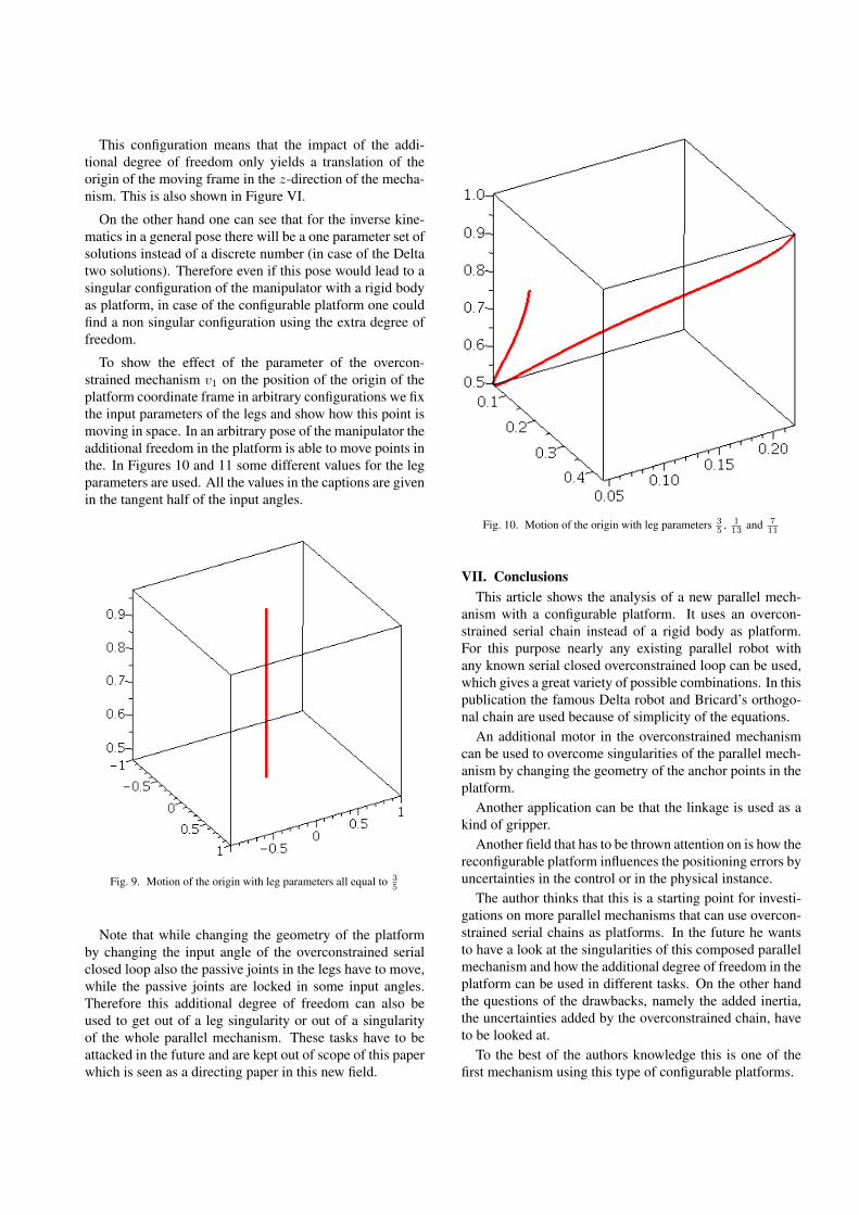
To show the effect of the parameter of the overcon-strained mechanism v1 on the position of the origin of theplatform coordinate frame in arbitrary configurations we fixthe input parameters of the legs and show how this point ismoving in space. In an arbitrary pose of the manipulator theadditional freedom in the platform is able to move points inthe. In Figures 10 and 11 some different values for the legparameters are used. All the values in the captions are givenin the tangent half of the input angles.
Fig. 9. Motion of the origin with leg parameters all equal to 35
Note that while changing the geometry of the platformby changing the input angle of the overconstrained serialclosed loop also the passive joints in the legs have to move,while the passive joints are locked in some input angles.Therefore this additional degree of freedom can also beused to get out of a leg singularity or out of a singularityof the whole parallel mechanism. These tasks have to beattacked in the future and are kept out of scope of this paperwhich is seen as a directing paper in this new field.
Fig. 10. Motion of the origin with leg parameters 35
, 113
and 711
VII. ConclusionsThis article shows the analysis of a new parallel mech-
anism with a configurable platform. It uses an overcon-strained serial chain instead of a rigid body as platform.For this purpose nearly any existing parallel robot withany known serial closed overconstrained loop can be used,which gives a great variety of possible combinations. In thispublication the famous Delta robot and Bricard’s orthogo-nal chain are used because of simplicity of the equations.
An additional motor in the overconstrained mechanismcan be used to overcome singularities of the parallel mech-anism by changing the geometry of the anchor points in theplatform.
Another application can be that the linkage is used as akind of gripper.
Another field that has to be thrown attention on is how thereconfigurable platform influences the positioning errors byuncertainties in the control or in the physical instance.
The author thinks that this is a starting point for investi-gations on more parallel mechanisms that can use overcon-strained serial chains as platforms. In the future he wantsto have a look at the singularities of this composed parallelmechanism and how the additional degree of freedom in theplatform can be used in different tasks. On the other handthe questions of the drawbacks, namely the added inertia,the uncertainties added by the overconstrained chain, haveto be looked at.
To the best of the authors knowledge this is one of thefirst mechanism using this type of configurable platforms.

Fig. 11. Motion of the origin with leg parameters 75
, 613
and 911
References[1] J.-P. Merlet. Parallel Robots. Solid Mechanics and its Applications.
Kluwer, Dordrecht, 2000.[2] M. G. Mohamed and C. M. Gosselin. Design and analysis of kine-
matically redundant parallel manipulators with configurable plat-forms. IEEE Transactions on Robotics, 21(3):277–287, June 2005.
[3] B.-J. Yi, H. Y. Na, J. H. Lee, Y.-S. Hong, S.-R. Oh, I. Hong Suh, andWhee Kuk Kim. Design of a parallel-type gripper mechanism. TheInternational Journal of Robotics Research, 21(7):661–676, July2002.
[4] V. Nabat, M. de la O Rodriguez, O. Company, and S. Krut. Par4:very high speed parallel robot for pick-and-place. In InternationalConference on Intelligent Robots and Systems (IROS2005), pages553–558, August 2005.
[5] P. Lambert and J. L. Herder. Self dual topology of parallel mech-anisms with configurable platforms. In Proceedings of the 6thInternational Workshop on Computational Kinematics (CK2013),volume 15 of Mechanisms and Machine Science, pages 291–298.Springer Netherlands, 2013.
[6] A. G.L. Hoevenaars, P. Lambert, and J. L. Herder. Kinematic designof two elementary 3dof parallel manipulators with configurable plat-forms. In Proceedings of the 6th International Workshop on Compu-tational Kinematics (CK2013), volume 15 of Mechanisms and Ma-chine Science, pages 315–322. Springer Netherlands, 2013.
[7] P. Lambert. Parallel Robots with Configurable Plarforms. PhD the-sis, Technical University Delft, May 2013.
[8] R. Clavel. Delta, a fast robot with parallel geometry. In 18th Int.Symposium on Industrial Robot, pages 91–100, Lausanne, April 26-28 1988.
[9] R. Bricard. Lecon de Cinematique II. Gauthier-Villars, Paris, 1927.[10] D. R. Walter and M. L. Husty. On implicitation of kinematic con-
straint equations. In Machine Designe & Research, volume 26, pages218–226, 2010.
[11] M. L. Husty, M. Pfurner, and H.-P. Schrocker. Algebraic methods inmechanism analysis and synthesis. Robotica, 25(6):661–675, 2007.
[12] M. Pfurner. Analysis of spatial serial manipulators using kinematicmapping. PhD thesis, University of Innsbruck, October 2006.
[13] S. Kunze and H. Stachel. Uber ein sechsgliedriges raumlichesGetriebe. Elemente der Mathematik, 29(2):25–32, Marz 1974.
[14] M. Pfurner and M.L. Husty. A method to determine the motionof overconstrained 6R-mechanisms. In Proceedings of the 12thIFToMM World Congress, Besancon, France, June 2007.