analysis of blast resistant structure (tnt storage case study)
TRANSCRIPT

1
Analysis of Blast Resistant Structure (TNT Storage Case Study)
Majdi EL. Mukhtar 1,* and Abdelmonim A. Haroun2 1 Civil Engineering Department, Al-Zaiem Al-Azhari University, Khartoum, Sudan 2 Civil Engineering Department, University of Karary, Omdurman, Sudan
* Corresponding author: Majdi EL. Mukhtar (e-mail: [email protected]).
Article history: Received 27 February 2020, Received in revised form 4 November 2020, Accepted 11 November 2020
ABSTRACT The explosions produce extreme and unique loading on structures and can cause
widespread damage to the building’s structural elements. Design of blast resistant structures provides
structural integrity and acceptable levels of safety for buildings. The previous studies show that some
structural systems could provide substantial increase in protection against blasts. This paper
discussed the behavior of TNT loaded storage (a framed reinforced concrete .( the results of calculated
pressure. Using Reference (UFC)-3-340-02 [1] Equation and investigated that the average peak
reflected pressure close to 5000 Psi. CSI-ETABS Software 3D model shows that the structural system of
case study unsafe under 0.5 tons of TNT internal weight charge.
Keywords: Blast, TNT Storage, Reflected Pressure and confined
1. INTRODUCTION
This document is a template for Microsoft
Explosion in structural engineering usually used
to describe any situation where enormous energy
is released from a chemical or mechanical nuclear
source. However, from the perspective of the
effects of the blast load on framed concrete
storages that have highly an important factor, it
must be designed to resist blast loads which have
been recently concern of researchers to find out
appropriate structural systems. When explosion
occur inside the building such as propellant
storages called confined blast, on the other hand
the surrounding environment (Human, Buildings
and equipment’s) is the point of protection from
fragments and generated explosion energy.
Research by Hu et al. [7] shown that the pressure
time-history resulting from the vented confined
blast, affected with several factors, including the
size of the explosion charge, shape and location of
it, as well as the direction and the starting point of
detonation in the charge, on the other hand, the
confined explosion contains initial and
subsequent peak pressure resulting from the
shockwave's reflections of the boundary walls of
the interior, it is known as gas pressure or quasi
static pressure that continues to exist inside the
container unless there is an opening to escape.
However Baker et al.[8] the study showed
one-dimensional or two-dimensional charge in
simple form inside a fully closed container that
the subsequent peak pressure usually takes half
of the initial values as shown in Figure(1). This
pressure time-history can be obtained
analytically. According to, F.B.A. Beshara [6] the
evaluation of explosion-induced ground shocks
can be included in a simplified form. An
explosion which occurs within a structure
normally develops a very complex pressure
time-history at any position inside the structure
although the complex loading cannot be
predicted exactly”.
Fig. 1: Simplified confined pressure time-history proposed by
Baker et al. [8].
FJES Majdi Mukhtar and Abdelmonim Adam: Analysis of blast resistant structure (TNT storage case study)
2
2. BLAST PHENOMENON
Explosions are classified based on their nature
as chemical, physical and nuclear blast. The
energy will released as result of the atomic nuclei
formed by rearrangement of the protons and
neutrons in the interacting nuclei. Physical
explosion is the result of mixing highly reactive
liquids setting ablaze of explosive materials,
exploding of gas cylinders etc. however chemical
explosion is a result of quick oxidation of fuels
mainly which consists of carbon and hydrogen.
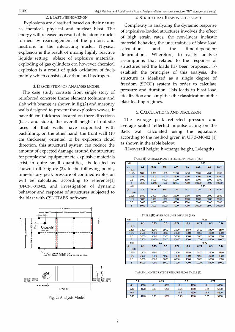
3. DESCRIPTION OF ANALYSIS MODEL
The case study consists from single story of
reinforced concrete frame element (columns and
slab with beams) as shown in fig.(2) and masonry
walls designed to prevent the explosion waves, It
have 40 cm thickness located on three directions
(back and sides), the overall height of out-site
faces of that walls have supported with
backfilling, on the other hand, the front wall (10
cm thickness) oriented to be explosion cloud
direction, this structural system can reduce the
amount of expected damage around the structure
for people and equipment etc. explosive materials
exist in quite small quantities, its located as
shown in the figure (2), In the following points,
time-history peak pressure of confined explosion
will be calculated according to reference[1]
(UFC)-3-340-02, and investigation of dynamic
behavior and response of structures subjected to
the blast with CSI-ETABS software.
Fig. 2: Analysis Model
4. STRUCTURAL RESPONSE TO BLAST
Complexity in analyzing the dynamic response
of explosive-loaded structures involves the effect
of high strain rates, the non-linear inelastic
material behavior, the uncertainties of blast load
calculations and the time-dependent
deformations. Wherefore, to easily analyze
assumptions that related to the response of
structures and the loads has been proposed. To
establish the principles of this analysis, the
structure is idealized as a single degree of
freedom (SDOF) system in order to calculate
pressure and duration. This leads to blast load
idealization and simplifies the classification of the
blast loading regimes.
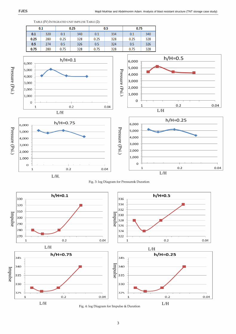
5. CALCULATIONS AND DISCUSSION
The average peak reflected pressure and
average scaled reflected impulse acting on the
Back wall calculated using the equations
according to the method given in UF 3-340-02 [1]
as shown in the table below:
(H=overall height, h =charge height, L=length)
TABLE (I) AVERAGE PEAK REFLECTED PRESSURE (PSI):
TABLE (II) AVERAGE UNIT IMPULSE (PSI):
TABLE (II) INTEGRATED PRESSURE FROM TABLE (I):
FJES Majdi Mukhtar and Abdelmonim Adam: Analysis of blast resistant structure (TNT storage case study)
3
Impulse
Im
pulse
Impulse
Impulse
L/H
L/H
L/H
L/H
L/H
L/H L/H.
L/H
TABLE (IV) INTEGRATED UNIT IMPLUSE TABLE (2):
0
1,000
2,000
3,000
4,000
5,000
6,000
0.040.21
h/H=0.5
0
1,000
2,000
3,000
4,000
5,000
6,000
0.040.21
h/H=0.25
Fig. 3: log Diagram for Pressure& Duration
Fig. 4: log Diagram for Impulse & Duration
Pressu
re (Psi.
(
Pressu
re (Psi.
(
Pressu
re (Psi.
( P
ressure (P
si. (

FJES Majdi Mukhtar and Abdelmonim Adam: Analysis of blast resistant structure (TNT storage case study)
3
L/H
The Peak pressure time-history have been
calculated according to UFC-340-20 Ref. [1]
equations as shown above Tables (I&III), this
values is very large among existed structural
system, it does not need to prove stability of
structure under amount of 0.5 TONS of TNT
internal loading on the part of structure, however
CSI-ETABS model shows that the displacement of
joints on the beam columns connection around 9
meters as shown in table (V) this values does not
applicable in the structural engineering, indeed
whole structures can be fragments which are
cause huge damages around it. Hence the
structural system currently presented did not
approached with amount TNT of inside storage.
Fig. 7: SCI-ETABS 3D Model dynamic analysis
TABLE (V) JOINTS DISPLACEMENT SCI-ETABS:
Fig. 5: YY-axis view over stress columns dynamic analysis and
design (ETABS)
Fig. 6: XX-axis view over stress columns dynamic analysis and
design (ETABS)
A. Conclusion
Analysis of propellants' storages, no matter
how small quantities, it high recommended to
preventing explosions causes. This paper
indicates that the blast resistance systems needs
to experimental studies in term of investigate
exact response of structure. The internal
explosions in storages of propellants are very
complicated hence we recommend that structural
systems must be underground, in order to
achieve design concept, reinforced concrete
elements should be high strength and protected
from temperature of leakage gas Finally, to
develop software model LS-DYANA Program is
more likely.
h/H Average Pressure
0.1 4800
0.167 4980
0.25 5200
0.5 5300
0.75 5300
4,700
4,800
4,900
5,000
5,100
5,200
5,300
5,400
0.040.21
Average peak reflected pressure on Structures
Pressu
re
4

FJES Majdi Mukhtar and Abdelmonim Adam: Analysis of blast resistant structure (TNT storage case study)
3
REFERENCES
[1] Unified Facilities Criteria (UFC)-3-340-02 (2008), Structures
to Resists the Effects of Accidental Explosions, US Army
Corps of Engineers, Naval Facilities Engineering
Command, Air Force Civil Engineer Support Agency.
[2] Qureshi Rizwan, Shivanand Ghule, Amarnath, Structural
Analysis of Blast Resistant Buildings. International
Research Journal of Engineering and Technology (IRJET)
Aug -2017.
[3] C.F. Zhao, J.Y. Chen, Y. Wang, S.J. Lu. Damage mechanism
and response of reinforced concrete containment structure
under internal blast loading, Theoretical and Applied
Fracture Mechanics 61 (2012) 12–20
[4] T. Ngo, P. Mendis, A. Gupta & J. Ramsay, Blast Loading
and Blast Effects on Structures – An Overview EJSE
Special Issue: Loading on Structures (2007).
[5] Zac Liskay, Shane Rugg, Conor Thompson. Blast
Resistant Building Design: Building Behavior and Key
Elements 2014.
[6] F. B. A. BESHARA MODELLING OF BLAST LOADING
ON ABOVEGROUND STRUCTURES-II. INTERNAL
BLAST AND GROUND SHOCK, 30 March 1992).
[7] Hu Y, Wu C, Lukaszewicz M, Dragos J, Ren J, Haskett M.
Characteristics of confined blast loading in unvented
structures. Int J Protect Struct 2011;2(1):21–43
[8] Baker WE, Cox PA, Westine PS, Kulesz JJ, Strehlow RA.
Fundamental studies in engineering. Explosion hazards
and evaluation, vol. 5. Amsterdam, Oxford, New York:
Elsevier; 1983. p. 238–43.
[9] Feldgun VR, Karinski YS, Yankelevsky DZ. Some
characteristics of an interior explosion within a room
without venting. Struct Eng Mech 2011;38(5):633–49.
[10] Gautham T N1, Dr. M N Hegde 2, Blast Resistant Buildings
(2017) International Research Journal of Engineering and
Technology (IRJET).
[11] [11] TM5-1300. Structures to resist the effects of accidental
explosions. United States Departments of the Army, Navy
and Air Force
[12] ] TM5-1300. Structures to resist the effects of accidental
explosions. United States Departments of the Army, Navy
and Air Force.
5