analysis of deep space radiation protection
TRANSCRIPT

2019Team 343
Problem A
Analysis of deep space radiation protection
Abstract
This paper analyzes various options for spacecraft to prevent radiationin deep space (the spacecraft is set to a cylindrical shape with a base radiusof 5.42m, a height of 10.84m, and a volume of approximately 1000m3). Wepropose a solution based on both superconducting magnetic shielding andpassive protection, which has a total weight of 16.53 tons, and the super-conducting material is BSCCO-2212 with a density of 1.8954g/cm3.
It is an attempt to find the relatively feasible configuration for block-ing high energy particles, which can be deflected by electromagnetic field.Computer simulation was used to calculate the efficiency of possible mag-netic field structures in 8 plans, and one of the schemes is considered to besuperior (80% of high-energy particles can be shielded by superconductingmagnetic field with strength B=10T, thickness L=2 m). The blind zone ofthe magnetic field structure is considered, and an aluminum plate with aradius of 2 m and a thickness of 10 mm is mounted on the top of the space-craft. In addition to setting the superconducting magnetic shielding fieldto deflect high-energy particles, we cover the spacecraft with a 3.75 mmaluminum plate to absorb gamma rays.
The findings show that in this scheme can block 94% of high-energyelectrons with energy not exceeding 4Gev/n and 98% of γ-rays with a fre-quency of 1020 Hz. In addition, possible problems such as the damage ofthe strong magnetic field to the human body and the explosion of SCRs arealso considered.
Team # 343 Page 1 of 24
Contents
1 Introduction 2
1.1 Background . . . . . . . . . . . . . . . . . . . . . . . . . . . . . . . . 2
1.2 Cosmic radiation environment . . . . . . . . . . . . . . . . . . . . . 2
1.3 Radiation prevention method . . . . . . . . . . . . . . . . . . . . . . 2
2 Assumptions and Symbols 3
2.1 Assumptions . . . . . . . . . . . . . . . . . . . . . . . . . . . . . . . . 3
2.2 Notations . . . . . . . . . . . . . . . . . . . . . . . . . . . . . . . . . . 4
3 Model 4
3.1 magnetic active protection . . . . . . . . . . . . . . . . . . . . . . . . 5
3.1.1 Principle of deflection . . . . . . . . . . . . . . . . . . . . . . 5
3.1.2 Basic structure of shielding magnetic field . . . . . . . . . . 7
3.2 Design and analysis of shielded magnetic field structure . . . . . . 10
3.2.1 Eight combined shielding magnetic field structures . . . . . 10
3.2.2 Investigate shielding effectiveness of eight different mag-netic field structures . . . . . . . . . . . . . . . . . . . . . . . 11
3.2.3 Select the best structure . . . . . . . . . . . . . . . . . . . . . 12
3.3 Passive protection of materials . . . . . . . . . . . . . . . . . . . . . 13
3.3.1 Magnetic shielding blind zone protection . . . . . . . . . . . 13
3.3.2 Cosmic gamma ray protection . . . . . . . . . . . . . . . . . 14
4 Model solving and analysis 15
4.1 Model solving . . . . . . . . . . . . . . . . . . . . . . . . . . . . . . . 15
4.1.1 Active protection structure . . . . . . . . . . . . . . . . . . . 15
4.1.2 Passive protection structure . . . . . . . . . . . . . . . . . . . 18
4.2 Quality Analysis . . . . . . . . . . . . . . . . . . . . . . . . . . . . . . 18
4.3 Analysis of protection effect . . . . . . . . . . . . . . . . . . . . . . . 21
4.4 Feasibility analysis . . . . . . . . . . . . . . . . . . . . . . . . . . . . 21
5 Model advantages and disadvantages 22
Team # 343 Page 2 of 24
5.1 Advantages . . . . . . . . . . . . . . . . . . . . . . . . . . . . . . . . 22
5.2 Disadvantages . . . . . . . . . . . . . . . . . . . . . . . . . . . . . . . 22
6 Conclusions 23
References 23
1 Introduction
1.1 Background
Cosmic radiation has negative effect on peoples health. It may lead to thedamage of astronauts’ genetic material and destroy the normal physiologicalfunction of human body. In some cases, the cosmic radiation can cause fataldiseases (leukemia, cancer). Therefore, cosmic radiation is supposed to be anessential issue in manned space flight.[1]
1.2 Cosmic radiation environment
Cosmic radiation consists of two parts: high-energy particle and high-frequencyelectromagnetic radiation(γ-ray).
High-energy particle is the main components, accounting for approximately98%. It comes mainly from Earth’s Radiation Belts (ERBs), Solar Cosmic Radi-ation (SCRs), and Galaxy Cosmic Rays (GCRs) [2]. SPEs and GCRs are majorthreats to astronaut safety in deep space exploration of manned spaceflight.
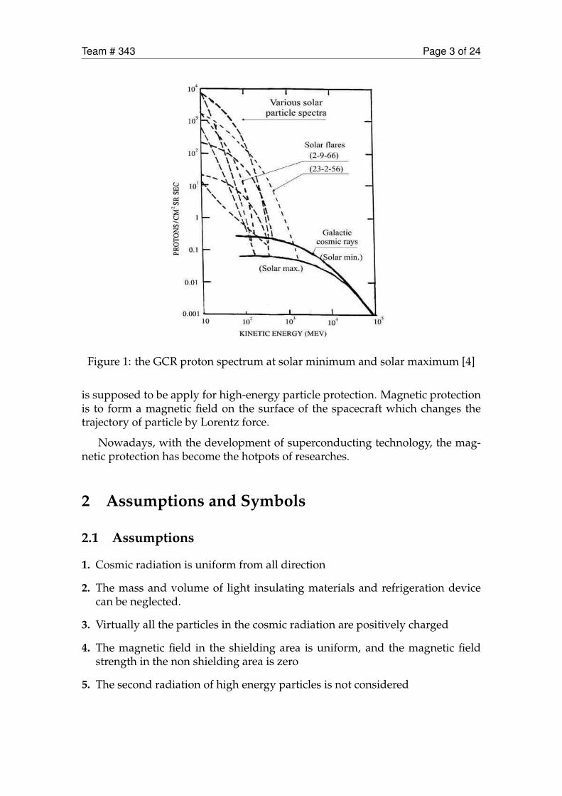
According to NASA reports [3]. GCRs are stable high-energy particle back-ground sources with a radiation dose of 0.6 Sv/a and particle energy of about 1GeV/n. SPEs are powerful source of particle transients, and the intensity and en-ergy spectrum of each SPE is different. Picture 1 shows the GCR proton spectrumat solar minimum and solar maximum [4].
1.3 Radiation prevention method
Nowadays, the main approaches in cosmic radiation protection are the pas-sive protection (the surface is thickened with radiation resistant materials) andmagnetic active protection.
The traditional passive protection methods can effectively reduce the influ-ence of high frequency electromagnetic radiation. However, this method ap-pears to have little effect in high-energy particle. Therefore, the active protection
Team # 343 Page 3 of 24
Figure 1: the GCR proton spectrum at solar minimum and solar maximum [4]
is supposed to be apply for high-energy particle protection. Magnetic protectionis to form a magnetic field on the surface of the spacecraft which changes thetrajectory of particle by Lorentz force.
Nowadays, with the development of superconducting technology, the mag-netic protection has become the hotpots of researches.
2 Assumptions and Symbols
2.1 Assumptions
1. Cosmic radiation is uniform from all direction
2. The mass and volume of light insulating materials and refrigeration devicecan be neglected.
3. Virtually all the particles in the cosmic radiation are positively charged
4. The magnetic field in the shielding area is uniform, and the magnetic fieldstrength in the non shielding area is zero
5. The second radiation of high energy particles is not considered
Team # 343 Page 4 of 24
2.2 Notations
The primary notations used in this paper are listed in Table 3.3.2. There canbe some other notations to be described in other parts of the paper.
Symbol Definition
B magnetic field intensityL Magnetic field thicknessH the height of the protection areaq Electric quantity of charged particlesγ Lorentz Factor
θAngle (throwing angle) between incident direction ofcharged particles and shielding magnetic field
m0 Static mass of charged particlesT Kinetic energy of charged particles
TC/O
The minimum kinetic energy (up to kinetic energy)required to designate point p through the protectionzone.
r0 the outer diameter of the shielding area
rpthe radius of the thicken area in the top end of protec-tion area
ri the radius of the protection area
3 Model
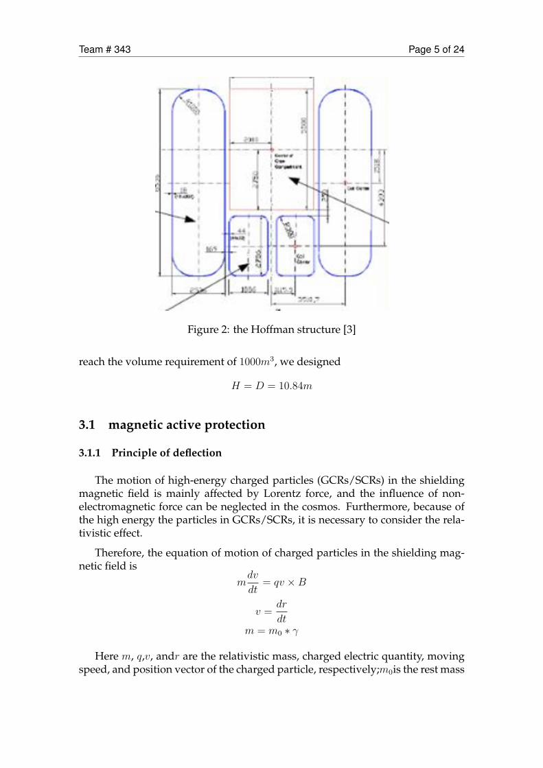
In previously research [4], Hoffman had already studied this problem. Heproposed a ring magnetic field configuration.
It is composed of two nested concentric cylinders. The small cylinder is theprotection area (protected area). The area between the large and small cylindersis full of magnetic field. The two ends of the whole structure are called the endcover area and the middle is called the barrel area.
However, passive protection was not considered in this structure. Besides,some part of the magnetic field configuration cannot block the cosmic radia-tion effectively. In this paper, we decided to build the model combined boththe passive protection and active protection based on the Hoffmans structure,which was proved to have better results in cosmic radiation protection underfinite mass and volume.
We designed the protection area which is similar to the Huffuman. The heightH of the protection area is equal to the bottom diameterD. Therefore, in order to
Team # 343 Page 5 of 24
Figure 2: the Hoffman structure [3]
reach the volume requirement of 1000m3, we designed
H = D = 10.84m
3.1 magnetic active protection
3.1.1 Principle of deflection
The motion of high-energy charged particles (GCRs/SCRs) in the shieldingmagnetic field is mainly affected by Lorentz force, and the influence of non-electromagnetic force can be neglected in the cosmos. Furthermore, because ofthe high energy the particles in GCRs/SCRs, it is necessary to consider the rela-tivistic effect.
Therefore, the equation of motion of charged particles in the shielding mag-netic field is
mdv
dt= qv ×B
v =dr
dtm = m0 ∗ γ
Here m, q,v, andr are the relativistic mass, charged electric quantity, movingspeed, and position vector of the charged particle, respectively;m0is the rest mass
Team # 343 Page 6 of 24
of the particle; γ is the Lorentz factor; B is the shielding magnetic field strengthat r.
Under the effect of Lorentz force, the charged particles appear to do approx-imately circle motion on the plane of the vertical shielding magnetic field. Theradius of gyration is also called the Larmor radius. The expression is [5]
rL =γm0v⊥qB
v⊥ = vsinθ
θ is the angle between the charged particle entering direction of v and theshielding magnetic fieldB.
Assuming that the shielding magnetic field thickness is L, when L >= 2rL,the charged particles will be almost completely shielded. When L < 2rL, part ofthe charged particles are shielded by the magnetic field.
It can be seen from the above formula() that when the kinetic energy of theshielding magnetic field B and the kinetic energy of GCRs/SCRs are constant,the deflection effect of shielding magnetic field is similar for elements with atom-ic number Z ≥ 2 which have the approximately equal ratio m0/q. Therefore, inthis paper, H and He elements are selected as typical GCRs/SCRs particles.
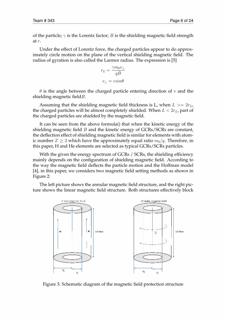
With the given the energy spectrum of GCRs / SCRs, the shielding efficiencymainly depends on the configuration of shielding magnetic field. According tothe way the magnetic field deflects the particle motion and the Hoffman model[4], in this paper, we considers two magnetic field setting methods as shown inFigure 2:
The left picture shows the annular magnetic field structure, and the right pic-ture shows the linear magnetic field structure. Both structures effectively block
Figure 3: Schematic diagram of the magnetic field protection structure
Team # 343 Page 7 of 24
the side GCRs/SCRs particles, but have virtually no protective effect in the di-rection of the top cover. We discussed the two basic structures below and thencombine the two structure (with some protection in the direction of the top cov-er).
3.1.2 Basic structure of shielding magnetic field
1. Linear magnetic field structure
In linear magnetic field structure, the magnetic field between the large andsmall cylinders is linear type.
Figure 4: Linear shielded magnetic field structure [6]
For the particles incident on the side of barrel, figure 4 shows the motion orbitof charged particles in the shielding area and the protection area. The velocity ofparticles perpendicular to magnetic field. The azimuth angle between the veloc-ity of charged particles and the magnetic field is defined as α.
In the shielded area, the electrons make a curve motion because of the Lorentzforce, and the charged particles in the protection zone make a linear motion.
Here, we define the cut-off kinetic energy TC/O as the minimum kinetic ener-gy required for incident particles to pass through the shielded magnetic field toenter the protection area,
The deflection of charged particles on the way is divided into two categories:
In the first type, particles with kinetic energy T ≤ TC/O cannot pass throughthe shielded magnetic field from all azimuth angle (0 ≤ ≤ 180) .
In the second category, particles with kinetic energy T > TC/O can pass throughthe shielded magnetic field from some azimuth angle.
In conclusion, TC/O is the minimum kinetic energy required to pass the mag-netic field. The moving orbit cut-off kinetic energy TC/O is called the limit orbit,and the radius of the orbit corresponding to the shielding zone is called the crit-ical Larmor radius rL,0. [7]
Assume that the magnetic field thickness is L and the magnetic inductionintensity is B. The velocity of the incident particle is V , the amount of charge is

Team # 343 Page 8 of 24
ǡݎ ݎ
ݎ
B
ݒ
Figure 5: Motion track of charged particles in the shielded areas
q, and the static mass is m0. In order to prevent the particle from entering theprotection zone
r ≤ rL,0
2 ∗ rL,0 = L
γ =√
1− v2/c2
T = m0c2(γ − 1)
Therefore:
B ≥ 2× T/C2 +m0
ql
If we obtain the particle type, energy, the magnetic field thickness and theminimum magnetic field strength, the minimum B can be calculated as:
B = 2× T/C2 +m0
ql
However, the flux of magnetic field in the two end cover area is reduced tozero. Therefore, the high-energy charged particles incident from the two ends ofthe cover area can enter the protection area without limitation.
2. annular shielded magnetic field structure and cut-off kinetic energy
Team # 343 Page 9 of 24
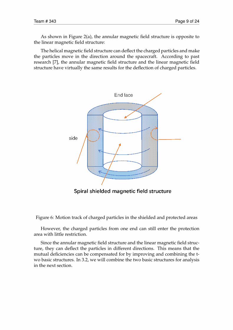
As shown in Figure 2(a), the annular magnetic field structure is opposite tothe linear magnetic field structure:
The helical magnetic field structure can deflect the charged particles and makethe particles move in the direction around the spacecraft. According to pastresearch [7], the annular magnetic field structure and the linear magnetic fieldstructure have virtually the same results for the deflection of charged particles.
Figure 6: Motion track of charged particles in the shielded and protected areas
However, the charged particles from one end can still enter the protectionarea with little restriction.
Since the annular magnetic field structure and the linear magnetic field struc-ture, they can deflect the particles in different directions. This means that themutual deficiencies can be compensated for by improving and combining the t-wo basic structures. In 3.2, we will combine the two basic structures for analysisin the next section.
Team # 343 Page 10 of 24
3.2 Design and analysis of shielded magnetic field structure
When the magnetic field strength B is large enough B ≥ 2 ×TC2+m0
qlthe ra-
diation particles of the entering the protection zone mainly come from the endcover area. In this chapter, eight combined magnetic field structures are designedto reduce the radiation from the end cover area. In addition, we investigate theoverall shielding efficiency of the combination of different basic magnetic fieldstructures.
The shielding effect of shielding magnetic field structure, strength B andthickness L on typical GCRs H and He (2GeV-4GeV) particles was comparedand the protective effects of H and He spectra in typical GCR events were fur-ther investigated.
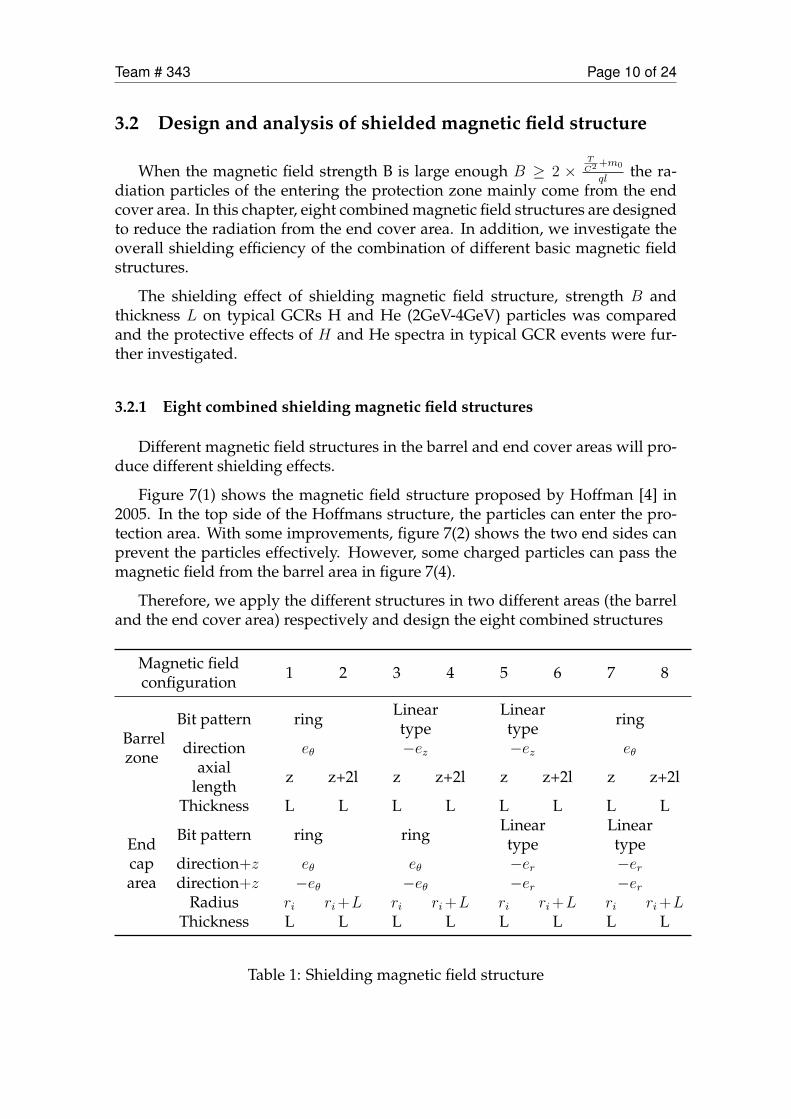
3.2.1 Eight combined shielding magnetic field structures
Different magnetic field structures in the barrel and end cover areas will pro-duce different shielding effects.
Figure 7(1) shows the magnetic field structure proposed by Hoffman [4] in2005. In the top side of the Hoffmans structure, the particles can enter the pro-tection area. With some improvements, figure 7(2) shows the two end sides canprevent the particles effectively. However, some charged particles can pass themagnetic field from the barrel area in figure 7(4).
Therefore, we apply the different structures in two different areas (the barreland the end cover area) respectively and design the eight combined structures
Magnetic fieldconfiguration 1 2 3 4 5 6 7 8
Barrelzone
Bit pattern ring Lineartype
Lineartype ring
direction eθ −ez −ez eθaxial
length z z+2l z z+2l z z+2l z z+2l
Thickness L L L L L L L L
Endcaparea
Bit pattern ring ring Lineartype
Lineartype
direction+z eθ eθ −er −erdirection+z −eθ −eθ −er −er
Radius ri ri+L ri ri+L ri ri+L ri ri+LThickness L L L L L L L L
Table 1: Shielding magnetic field structure

Team # 343 Page 11 of 24
Figure 7: Weak area of different structures
Where ri represents the radius of the protection zone, Z represents the lengthof the protection zone, L is the thickness of the shielding magnetic field, ez is theaxial direction of the barrel zone, er is the radial direction of the barrel zone, andeθ satisfies the right hand annular relationship.
3.2.2 Investigate shielding effectiveness of eight different magnetic field struc-tures
In this part, we use the computer to stimulate the movement of the particle indifferent magnetic field structure.
In order to evaluate the shielding effect of the magnetic field, we adopt themethod used by Hoffman [4] to investigate the shielding efficiency of the mag-netic field by calculating the reduction rate η. The calculation formula is:
η = 1− nin2/nin1
Here, nin1 and nin2 represent the number of particles entering the protectionzone without and with a magnetic field respectively.
Since the initial particles (GCRs) are Isotropy outside the shielded magneticfield, we assume that the particles are incident at a spherical source. The paper
Team # 343 Page 12 of 24
Figure 8: Eight different structrues of magnetic field
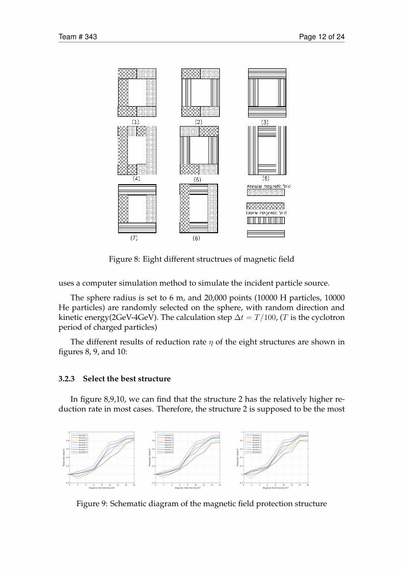
uses a computer simulation method to simulate the incident particle source.
The sphere radius is set to 6 m, and 20,000 points (10000 H particles, 10000He particles) are randomly selected on the sphere, with random direction andkinetic energy(2GeV-4GeV). The calculation step ∆t = T/100, (T is the cyclotronperiod of charged particles)
The different results of reduction rate η of the eight structures are shown infigures 8, 9, and 10:
3.2.3 Select the best structure
In figure 8,9,10, we can find that the structure 2 has the relatively higher re-duction rate in most cases. Therefore, the structure 2 is supposed to be the most
0 2 4 6 8 10 12 14 16
Magnetic field intensity B/T
-0.2
0
0.2
0.4
0.6
0.8
1
structure 1structure 2structure 3structure 4structure 5structure 6structure 7structure 8
0 2 4 6 8 10 12 14 16
Magnetic field intensity B/T
-0.2
0
0.2
0.4
0.6
0.8
1
structure 1structure 2structure 3structure 4structure 5structure 6structure 7structure 8
0 2 4 6 8 10 12 14 16
Magnetic field intensity B/T
-0.2
0
0.2
0.4
0.6
0.8
1
structure 1structure 2structure 3structure 4structure 5structure 6structure 7structure 8
Figure 9: Schematic diagram of the magnetic field protection structure
Team # 343 Page 13 of 24
effective structure.
When B is relatively low (B = 2T ), the reduction rate η can be negative insome structures, which proves that the magnetic field may have negative effecton the radiation protection.
Besides, the reduction effect η increases together with B. it rises rapidly afterB = 4T , until B = 10T . Then the shielding effect remains almost unchanged.
The shielding effect increases quite slowly with the increase of L, when con-sider the size of the structure, we can choose L = 2m Therefore, we will select themagnetic field thickness L = 2m and the magnetic field strength B = 10T as thestandard in the design of structure. In this condition(B=10T,L=2m),the structure2 can prevent about 81% of the radiation.
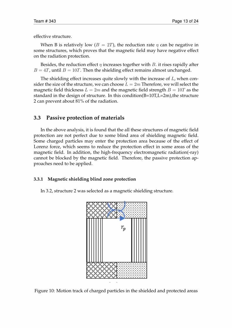
3.3 Passive protection of materials
In the above analysis, it is found that the all these structures of magnetic fieldprotection are not perfect due to some blind area of shielding magnetic field.Some charged particles may enter the protection area because of the effect ofLorenz force, which seems to reduce the protection effect in some areas of themagnetic field. In addition, the high-frequency electromagnetic radiation(-ray)cannot be blocked by the magnetic field. Therefore, the passive protection ap-proaches need to be applied.
3.3.1 Magnetic shielding blind zone protection
In 3.2, structure 2 was selected as a magnetic shielding structure.
Figure 10: Motion track of charged particles in the shielded and protected areas
Team # 343 Page 14 of 24
As shown, the solution has a blind spot on one side of the end cap region.Here the shielding efficiency is close to zero. According to document [11], Theabsorption of high-energy charged particles by metals can be expressed by equa-tions:
ϕ(E) = ϕ′(e)S(E ′)
S(E)exp(σAd)
Where d is the thickness of the shielding material, is the macroscopic absorp-tion cross section of the particle,ϕ(E), ϕ′(e)respectively represent the particle fluxof the extra-chamber energy and the energy entering the cabin reduced to E,S(E), S(E ′) represent the barrier power of the shielding material (here is alu-minum) for the two energy particles.
The energy before and after the particles penetrate the shielding material hasthe following relationship:
E = R−1[R(E) + d]
Where R(E) is the range of the particle with energy E, represents a negationfunction. If the particle range is less than d, it is blocked in the shielding material.We hope that the aluminum layer can shield 90%S(E′)
S(E)= 0.1energy particles in
the end cap area. Calculated:d10mm
This means that the end cap area needs to be mounted with a 10 mm thick alu-minum plate to shield 90% of the high energy particles on the area of L2.
3.3.2 Cosmic gamma ray protection
High-frequency electromagnetic radiation can be absorbed by metals, accord-ing to the attenuation equation of γ rays in metals [9]:
I = I0exp(−µx)
Here I0 represents the initial intensity of the ray, I represents the residualstrength after passing through a section of the metal with a thickness x, and µ isthe attenuation coefficient. Generally, µ is a function of the atomic coefficient ofthe substance and the frequency of the rays. According to [8], the frequency ofthe γ ray in the cosmic radiation is about 1020Hz. Table 2 shows the attenuationcoefficient µ. of γ ray in some common metals [10]
By comparing the attenuation coefficient and density of different metals, it issupposed that aluminum is the most suitable as a passive protective layer mate-rial. (Aluminum is competent attenuation coefficient for ray absorption and hasrelatively lighter density)
In order to protect the safety of astronauts, at least 95% of γ rays are supposedto be absorbed:
I
I0= exp−µx ≤ 0.05

Team # 343 Page 15 of 24
material thicknessδ/mm
Attenuationcoefficient µ
Linear absorption coeffi-cient κ
aluminum 0.2 0.8 1aluminum 0.5 0.8 1.04aluminum 1 0.8 1.08iron 0.2 1.2 1.27iron 0.5 1.2 1.82iron 1 1.2 3.32copper 0.2 1.8 1.43copper 0.5 1.8 2.46copper 1 1.8 6.05Tantalum 0.2 7.5 4.48Tantalum 0.5 7.5 42.5Tantalum 1 7.5 1808
Table 2: Comparison of attenuation coefficients of four materials with differentthicknesses
Therefore, the material thickness x:
x ≥ −ln(0.05)/mu
The attenuation coefficient of the aluminum material is = 0.8, and x >= 3.75mm is obtained. Therefore, if 95% of gamma rays are to be absorbed, the surfaceof the spacecraft must cover at least 3.75 mm of aluminum.
4 Model solving and analysis
4.1 Model solving
In general, the protective layer of the spacecraft consists of an active protec-tive structure and a passive protective structure. The protection zone is a cylinderwith a radius of 5.42 m and a height of 10.84m.
4.1.1 Active protection structure
The active protection structure consists of two main parts: the end cover areaand the barrel area,
1. The end cover area In order to form the Annular magnetic field in the endcover area, we design this coil structure:
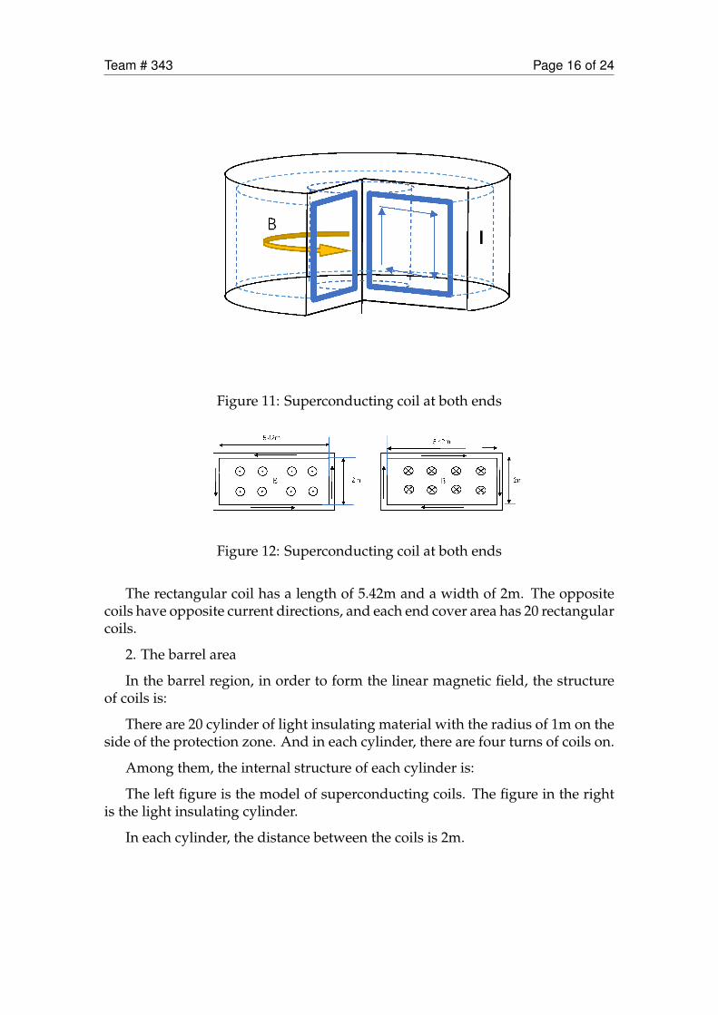
Team # 343 Page 16 of 24
Figure 11: Superconducting coil at both ends
Figure 12: Superconducting coil at both ends
The rectangular coil has a length of 5.42m and a width of 2m. The oppositecoils have opposite current directions, and each end cover area has 20 rectangularcoils.
2. The barrel area
In the barrel region, in order to form the linear magnetic field, the structureof coils is:
There are 20 cylinder of light insulating material with the radius of 1m on theside of the protection zone. And in each cylinder, there are four turns of coils on.
Among them, the internal structure of each cylinder is:
The left figure is the model of superconducting coils. The figure in the rightis the light insulating cylinder.
In each cylinder, the distance between the coils is 2m.

Team # 343 Page 17 of 24
Figure 13: Single side coil and Light insulating cylinder
Figure 14: Top view of side coil

Team # 343 Page 18 of 24
4.1.2 Passive protection structure
The passive protective structure consists of two main parts: the thickeningarea in the top and the bulkhead of spacecraft. 1. The bulkhead of spacecraft
The surface of the spacecraft is covered with 3.75 mm of aluminum. 2. thethickening area in the top:
10mm
Figure 15: thickened area in the top end
the aluminum plate on one side of the cover was thicker. The aluminum plateat top is set to 10 mm and a circular area having a radius of 2 m at the center ofthe end cap.
In addition, in order to fix the superconducting coil, light foam is used to fillbetween the superconducting coils.
In conclusion, the structure diagram of the spacecraft protective layer is:
4.2 Quality Analysis
The mass of the spacecraft’s protective layer includes the mass of the excita-tion coil in the end cap area, the mass of the excitation coil in the barrel, the massof the anti-gamma ray aluminum layer in the flight cabin and the mass of thethickened aluminum layer.
For a superconducting coil, the spatial magnetic field it excites can be calcu-lated by Biot-Savart Law:
B⃗ =
∫L
µ0I
4π
dl× e⃗rr2
Where µ0 is the permeability in vacuum, I is the current in the supercon-ducting coil, and r is the distance from a point in the space to the coil. dl is themicro-element of the superconducting coil segment.
We select the Superconducting material BSCCO-2212 to make the coil. Ac-cording to document [8], the density of BSCCO-2212 ρBSCCO−2212 = 1.8954g/cm3.Under the condition of 77K , the superconducting critical current density J =7100A/mm2.

Team # 343 Page 19 of 24
thicken area
in the top
Superconducting
coils at the side
Bulkhead
aluminum
瀁澔濠濕濭濙濦
Superconducting
coil at both ends
(20 turns)
Figure 16: Overall structure of the spacecraft

Team # 343 Page 20 of 24
1. Mass of end cap area excitation coil
The magnetic field strength at both ends of the protection zone is B = 10T ,and the magnetic permeability in vacuum is µ0 = 4π× 10−7T ∗m/A. The currentintensity I1 can be calculated according to Biot-Savart Law.
Therefore, the critical surface area of a superconducting wire is:
S1 = I1/J
Therefore, the mass of a single-turn superconducting coil is:
m1 = S1 ∗ 2 ∗ π ∗ r0 ∗ ρBSCCO−2212
Where r0 is the outer diameter of the shielding area Calculated that m1 =99.041kg There are 20 coil columns on the side of the protection zone, and eachcoil column has 4 turns of coils. The end cap area excitation coil total mass:
M1 = 20 ∗ 4 ∗m1 = 3.961 ∗ 103kg
2. Mass of barrel area excitation coil
The magnetic field strength on the side of the protection zone is B = 10T . Ac-cording to Biot-Savart Law, The current intensity I2 can be calculated. Therefore,the critical surface area of a superconducting wire is:
S2 = I2/J
The mass of a single-turn superconducting coil is:
m1 = S1 ∗ 2 ∗ ∗ r0 ∗ ρBSCCO−2212 = 83.8672kg
There are 20 coil columns at each end of the protection zone, and each coilcolumn has 1 coil. The end cap area excitation coil total mass:
M2 = 20 ∗m2 = 20 ∗ 2 ∗ π ∗ S2 ∗ r0 ∗ ρBSCCO−2212 = 6.709 ∗ 103kg
3. Mass of flight cabin anti-gamma ray aluminum layer
A layer of 3.75mm aluminum layer is evenly mounted on the surface of theprotection zone to prevent gamma rays. The quality of the aluminum layer is:
M3 = 2 ∗ π ∗ ri ∗ Ly + 2 ∗ π ∗ ri2 ∗ v ∗∆h
Where ri is the radius of the protection area, Ly is the length of the guard zone,v is the density of aluminum, and ∆h is the thickness of the aluminum layer.Brought into the calculation:
M3 = 5.5065 ∗ 103kg
4. Mass of Aluminum layer thickened part
Team # 343 Page 21 of 24
The thickened part of the aluminum layer is a circular area with a radius ofr = 2m, and the thickness is ∆L = 10mm, so the added mass is:
M4 = π ∗ r2 ∗ v ∗ (L−∆h)
Obtained M4 = 339.29kg Therefore, the total mass of the guard is
M = M1 +M2 +M3 +M4 = 16.53 ∗ 103kg = 16.53t
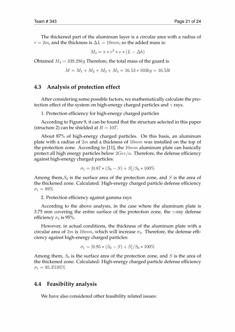
4.3 Analysis of protection effect
After considering some possible factors, we mathematically calculate the pro-tection effect of the system on high-energy charged particles and γ rays.
1. Protection efficiency for high-energy charged particles
According to Figure 9, it can be found that the structure selected in this paper(structure 2) can be shielded at B = 10T .
About 87% of high-energy charged particles. On this basis, an aluminumplate with a radius of 2m and a thickness of 10mm was installed on the top ofthe protection zone. According to [11], the 10mm aluminum plate can basicallyprotect all high energy particles below 2Gev/n. Therefore, the defense efficiencyagainst high-energy charged particles:
σ1 = [0.87 ∗ (S0 − S) + S]/S0 ∗ 100%
Among them,S0 is the surface area of the protection zone, and S is the area ofthe thickened zone. Calculated: High-energy charged particle defense efficiencyσ1 = 89%
2. Protection efficiency against gamma rays
According to the above analysis, in the case where the aluminum plate is3.75 mm covering the entire surface of the protection zone, the γ-ray defenseefficiency σ2 is 95%.
However, in actual conditions, the thickness of the aluminum plate with acircular area of 2m is 10mm, which will increase σ2. Therefore, the defense effi-ciency against high-energy charged particles:
σ1 = [0.95 ∗ (S0 − S) + S]/S0 ∗ 100%
Among them, S0 is the surface area of the protection zone, and S is the area ofthe thickened zone. Calculated: High-energy charged particle defense efficiencyσ1 = 95.3%95%
4.4 Feasibility analysis
We have also considered other feasibility related issues:
Team # 343 Page 22 of 24
1. The average ambient temperature of the Earth to Mars is 153K, which canreach 77K under the action of refrigerant. Meet the operating temperature ofthe BSCCO superconducting coil.
2. The magnetic field generated by the superconducting coil B=10T is harmfulto the human body. However, the structure of the coil is analyzed, and themagnetic fields generated by the superconducting coils symmetric about thecentral axis of the protection zone in the protection zone cancel each other out.In addition, a small anti-magnetic coil can be added to the spacecraft to ensuresafety. (The magnetic field does not harm the astronauts)
3. The lightweight insulating plastic is filled between the superconducting coilsto enhance the flight stability of the spacecraft.
4. If the spacecraft encounters an SCR outbreak during flight, it can enhance theshielding capability by temporarily increasing the current.
5 Model advantages and disadvantages
5.1 Advantages
1. The active protection scheme is set to reduce the weight of the spacecraft’souter casing.
2. Consider the blind zone of active protection and make up for it by means oflocal passive protection.
3. Compare 8 different magnetic field configuration schemes, choose a better so-lution, and enhance the shielding ability of radiation.
4. The computer simulation method was used to analyze the influence of mag-netic field strength B and magnetic field thickness L on the shielding effect,and the better B and T were selected.
5.2 Disadvantages
1. Protection against high energy uncharged particles is not considered.
2. The critical current density of BSCCO is not large enough and the operatingtemperature is low. Therefore, the magnetic field B generated by the magneticshield may not reach 10T.
Team # 343 Page 23 of 24
6 Conclusions
In this paper, various options for spacecraft to prevent deep space radiationare analyzed (the spacecraft is set to be cylindrical with a base radius of 5.42 me-ters, a height of 10.84 meters and a volume of about 1000m3). For the relativelyfeasible structures for blocking high-energy particles, the efficiency of possiblemagnetic field structures in the eight schemes are calculated by computer sim-ulation, of which scheme 2 is considered superior (87% of high-energy particlescan be shielded by superconducting magnetic fields with a strength of B = 10Tand a thickness of L = 2m). Considering the blind area of the magnetic fieldstructure, an aluminum plate with a radius of 2 m and a thickness of 10 mmis installed on the top of the spacecraft. In addition to setting superconductingmagnetic shielding fields to deflect high-energy particles, we also covered thespacecraft with a 3.75mm aluminum plate to absorb gamma rays. The resultsshow that the scheme can block 89% of high energy electrons with energy lessthan 2Gev/n and 95% of gamma rays with frequency of 1020 Hz.
References
[1] Xu Zhenhua. Radiation environment and radiation protection in mannedspace [C] / / abstracts of the 16th Symposium on space life of the ChineseAcademy of space sciences. 2005
[2] Townsend L W, Wilson J W, Shinn J L, et al. Human exposure to large solarparticle events in space[J]. Advances in Space Research, 1992, 12(2-3): 339-348.
[3] Hoffman J, Fisher P, Batishchev O. Use of superconducting magnet tech-nology for astronaut radiation protection[J]. Final Report for NIAC Phase IContract CP, 2005: 04-01.
[4] Hoffman J, Fisher P, Batishchev O. Use of superconducting magnet tech-nology for astronaut radiation protection[J]. Final Report for NIAC Phase IContract CP, 2005: 04-01.
[5] Griffith D J , Ruppeiner G . Introduction to Electrodynamics[J]. AmericanJournal of Physics, 1981, 49(12):1188-1189.
[6] http://www.chinatex.org/
[7] Zheng Hongxia. Study on the Mechanism of Magnetic Shielding Protectionagainst Space Radiation [D]. Nanjing University of Aeronautics and Astro-nautics, 2018.
[8] Tajmar M, Hense K, Marhold K, et al. Weight Measurements of HighTem-perature Superconductors during Phase Transition in Stationary, NonSta-
Team # 343 Page 24 of 24
tionary Condition and under ELF Radiation[C]//AIP Conference Proceed-ings. AIP, 2005, 746(1): 1290-1297.
[9] Zhang Lei, Jia Mingchun, Gong Junjun, Xia Wenming. Study on a fastmethod for calculating -ray mass attenuation coefficient based on MCNP[J]. journal of naval university of engineering, 2018,30(05):106-112.
[10] Chen Panxun. Experimental Measurement of X-ray Attenuation Coeffi-cients of Different Metal Materials for Different Energies [A] ... Annual Sci-entific Report of China Institute of Engineering Physics (2002)[C]: EditorialDepartment of Annual Scientific Report of China Institute of EngineeringPhysics, 2002:2.
[11] Ye Zonghai. On the shielding and protection of high-energy charged parti-cles [A]. Space Exploration Committee of the Chinese Society of Space Sci-ence. Proceedings of the 16th Academic Conference of the Space ExplorationCommittee of the Chinese Society of Space Science (II) [C]. Space Explo-ration Committee of the Chinese Society of Space Science: China Society ofSpace Science, 2003:14.