analysis of digital images using morphlogical …airccse.org/journal/jcsit/5113ijcsit12.pdf ·...
TRANSCRIPT
International Journal of Computer Science & Information Technology (IJCSIT) Vol 5, No 1, February 2013
DOI : 10.5121/ijcsit.2013.5112 145
ANALYSIS OF DIGITAL IMAGES USINGMORPHLOGICAL OPERATIONS
1.Amalorpavam.G
Dept Of Computer Applications, Sambhram Academy of Mgmt. StudiesBangalore, India,
[email protected]/[email protected]
2. Harish Naik T
Dept Of Computer Applications, Presidency CollegeBangalore, India,
3. Jyoti Kumari
Dept Of Computer Applications, ACHARYA INSTITUTES (AIGS)Bangalore, India,
4. Suresha M
Assistant Professor, Dept of computer ScienceJnana sahyadri,Kuvempu University, Karnataka,India
ABSTRACT
The main aim of this study is to transform the digital images into different forms. Image processingtechniques are used with wide varieties of applications. The requirement is different for differentapplications. This study is mainly focused on how to transform the image using mathematical morphologyso that it can be suitable for the respective applications.
Mathematical morphology has been chosen to explain how images are used to illustrate mathematical settheoretic operations, such as union, intersection by means of morphological operations like dilation anderosion.
These techniques are implemented in MATLAB using image processing algorithms. MATLAB is anexcellent tool to accomplish these tasks.
KEYWORDS
Image Analysis, Morphological Morphology, Dilation, Erosion, Opening and Closing Operation, hit-or-miss operation, thinning, thickens and gray-scale.
International Journal of Computer Science & Information Technology (IJCSIT) Vol 5, No 1, February 2013
146
1. INTRODUCTION
The field of digital image processing refers to processing digital images by means of a digitalcomputer. In image processing operations both the input and the output are images.
2. MATHEMATICAL MORPHOLOGY
2.1Basic morphological concepts
Mathematical morphology, which started to develop in the late 1960s, stands as a relativelyseparate part of image analysis. Mathematical morphology uses the concept of mathematical settheory for extracting meaning from the image.
A morphological transformation ψ is given by the relation of the image (point set X) with anothersmall point set B called a Structuring element. B is expressed with respect to a local origin O(called the representative point).
Morphological technique is a powerful tool for extracting features from an image.
2.1 Binary dilation and erosion
The set of black and white pixels constitute a description of a binary image. Assume that onlyblack pixels are considered, and the others are treated as a background. The primarymorphological operations are dilation and erosion, and from these two, more complexmorphological operations such as opening, closing, and shape decomposition can be constituted.
2.2 Dilation
The dilation operation thickens the image. The extent of how much it should be thicken is basedon the structuring element. The structuring element is a part of the image.
The morphological transformation dilation (+) combines two sets using vector addition. Thedilation operation can be done by performing vector addition of the pair of elements for both thesets X and B.
Example:
X={(1,0),(1,2),(1,2),(2,2),(0,3),(0,4)}B={(0,0),(1,0)}X(+)B = {(1,0),(1,2),(1,2),(2,2),(0,3),(0,4),
(2,0),(2,2),(2,2),(3,2),(1,3),(1,4)}
The input image as shown below in Fig. (1)

International Journal of Computer Science & Information Technology (IJCSIT) Vol 5, No 1, February 2013
147
Fig(1): Input Image
The dilated image is as shown in Fig(2)
Fig(2):Dilated Image
2.3 Erosion
The erosion operation performs either shrinking or thinning of the object. The extent of thisoperation is decided by the structuring element.
Erosion (-) combines two sets using vector subtraction of set elements is the dual operator ofdilation. Neither erosion nor dilation is an invertible transformation.
Example:
X={(1,0),(1,2),(1,2),(2,2),(0,3),(0,4)}B={(0,0),(1,0)}X(-)B = {(0,3),(1,3),(2,3)}
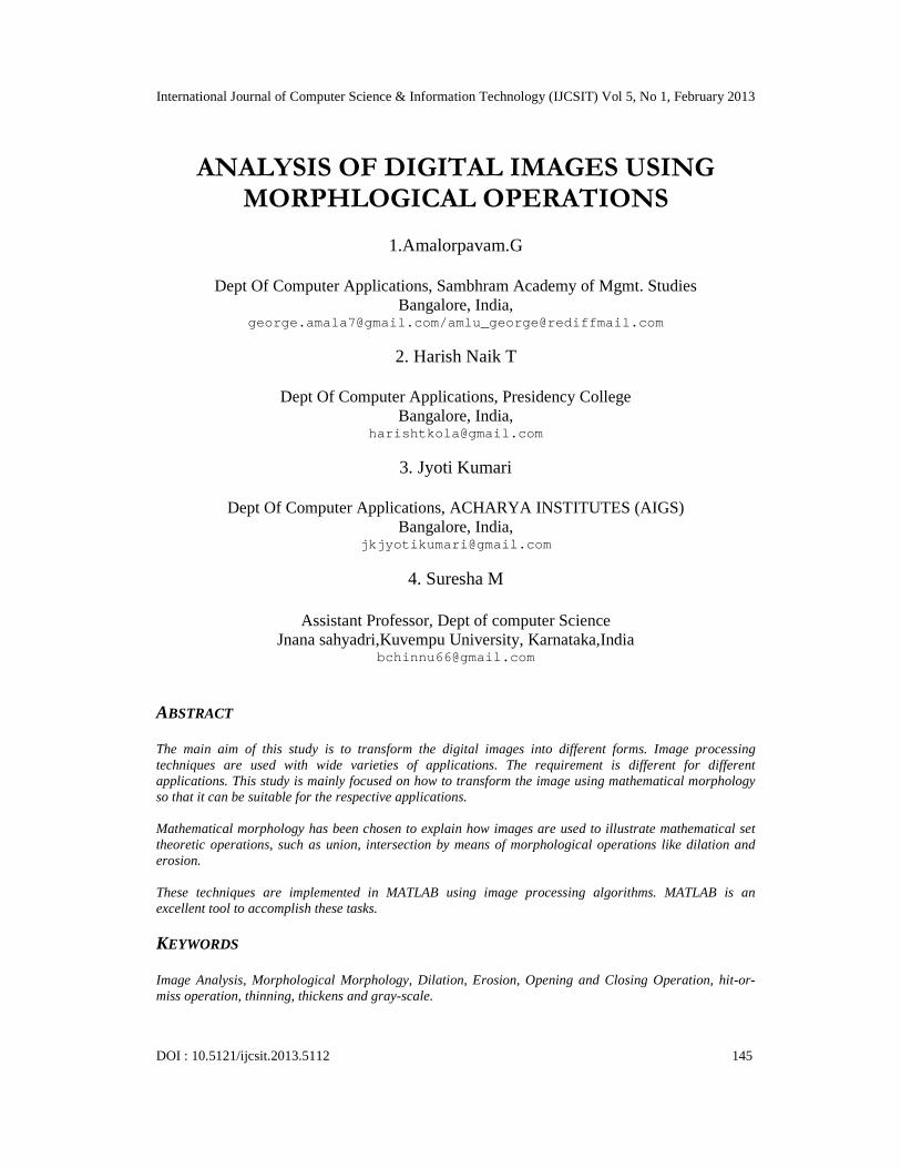
The result of Erosion operation with a disk of radius 2 is shown in Fig(3).The result of Erosion with a disk of radius 8 is shown in Fig (4).
Fig(3):Erosion with a disk of radius 2
International Journal of Computer Science & Information Technology (IJCSIT) Vol 5, No 1, February 2013
148
Fig(4):Erosion with a disk of radius 2
MATLAB Implementation
% Morphlogical operations dilation, erosionI=imread('d:\matlab704\work\leter1.bmp');figure,imshow(I);title('input image 1');B=[0 1 0; 1 1 1; 0 1 0];A2=imdilate(I,B);figure,imshow(A2),title('Dilated image');A=imread('d:\matlab704\work\leter1.bmp');figure,imshow(A);title('input image');se=strel('disk',8);A2=imerode(A,se);figure,imshow(A2);title('erosion with a disk of radius 8');se=strel('disk',5);A3=imerode(A,se);figure,imshow(A3);title('erosion with a disk of radius 5');se=strel('disk',2);A4=imerode(A,se);figure,imshow(A4),title('erosion with d disk of radius 2');
2.4 Opening and closing
We can’t get back the original image by performing erosion followed by dilation and vise versa.Instead, the result is a simplified and less detailed version of the original image.
Erosion followed by dilation creates an important morphological transformation called opening.The opening of an image X by the structuring element B is denoted by X ◦ B and is defined as
X ◦ B = ( X (-) B) (+) B
Dilation followed by erosion is called closing. The closing of an image X by the structuringelement B is denoted by X ● B and is defined as
X ● B =(X(+)B)(-)B
International Journal of Computer Science & Information Technology (IJCSIT) Vol 5, No 1, February 2013
149
If an image X is unchanged by opening with the structuring element B, is called open with respectto B. Similarly, if an image X is unchanged by closing with B, it is called closed with respect toB.
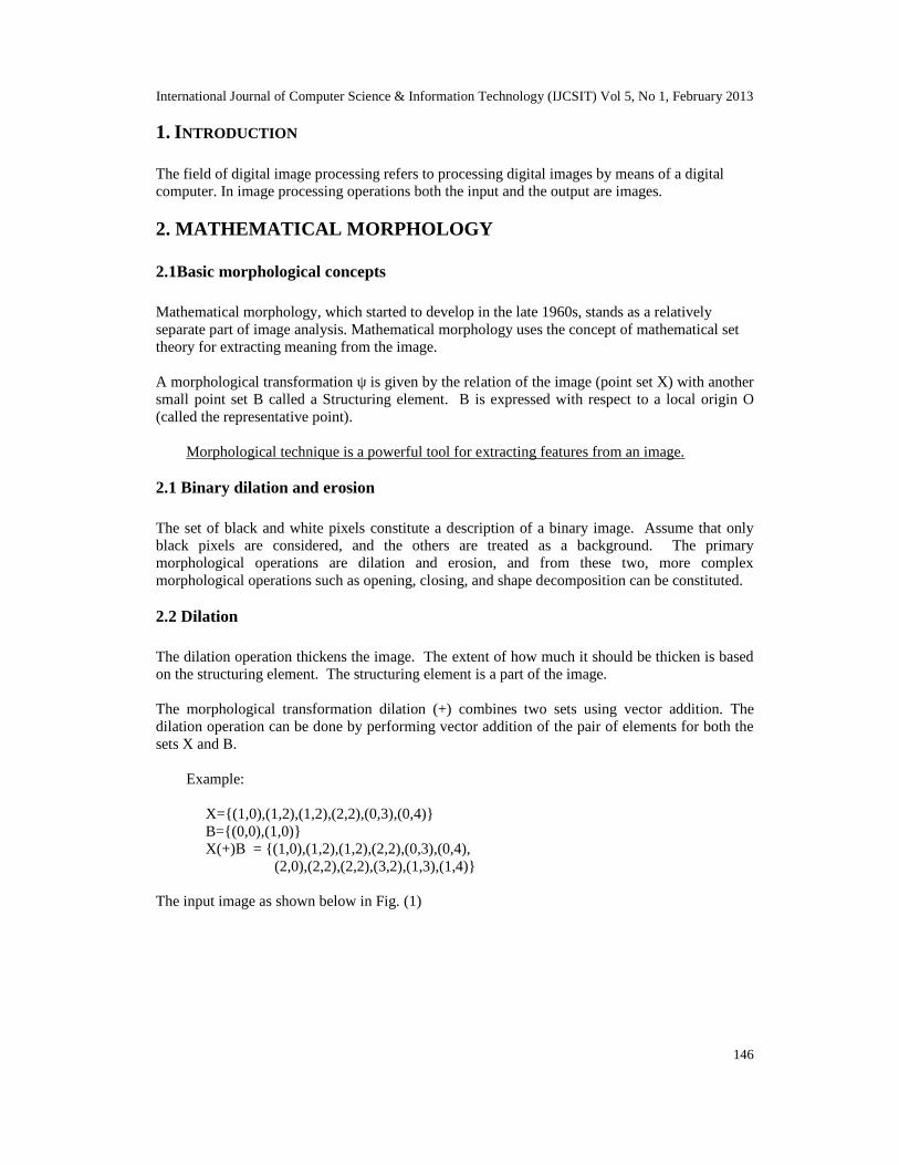
The original image selected for opening as in Fig(5).
Fig(5): Input Image
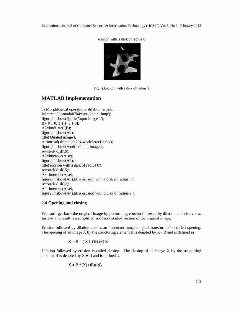
The result of opening as shown in Fig(6).
Fig(6): The resultant of opening
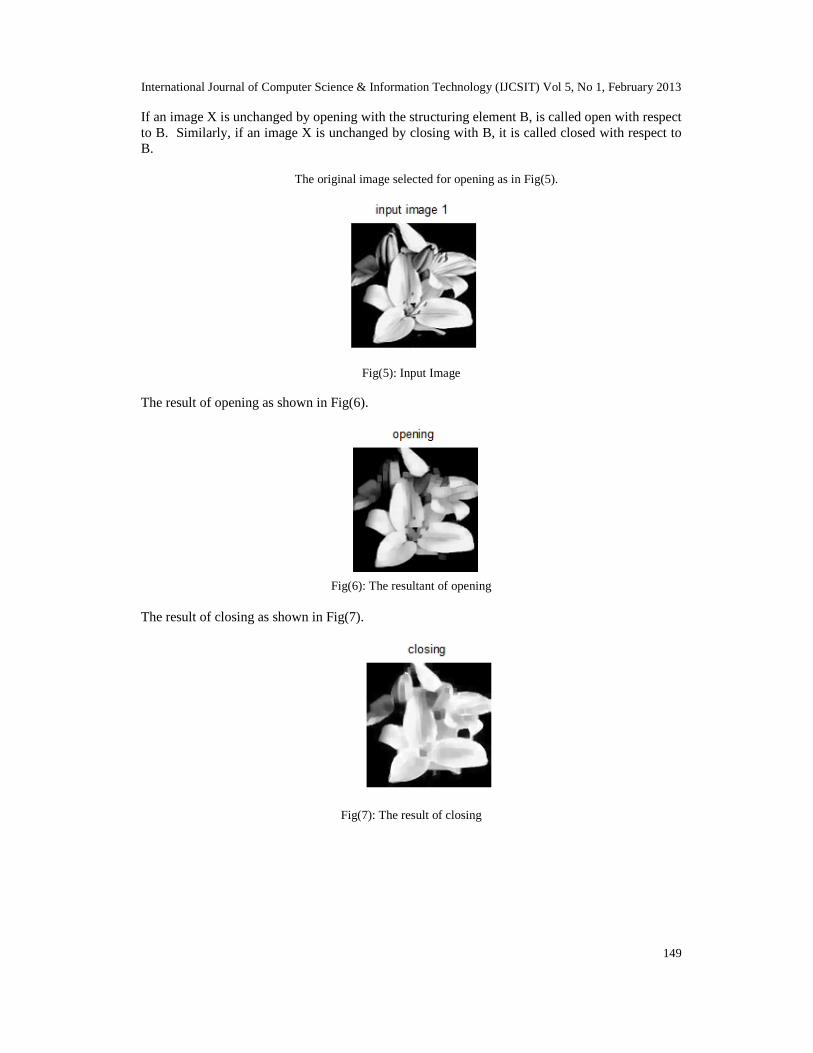
The result of closing as shown in Fig(7).
Fig(7): The result of closing
International Journal of Computer Science & Information Technology (IJCSIT) Vol 5, No 1, February 2013
150
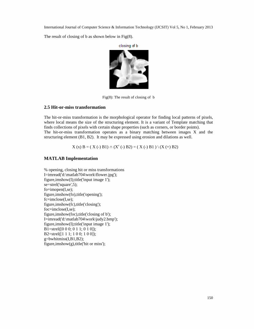
The result of closing of b as shown below in Fig(8).
Fig(8): The result of closing of b
2.5 Hit-or-miss transformation
The hit-or-miss transformation is the morphological operator for finding local patterns of pixels,where local means the size of the structuring element. It is a variant of Template matching thatfinds collections of pixels with certain shape properties (such as corners, or border points).The hit-or-miss transformation operates as a binary matching between images X and thestructuring element (B1, B2). It may be expressed using erosion and dilations as well.
X (x) B = ( X (-) B1) ∩ (Xc (-) B2) = ( X (-) B1 ) \ (X (+) B2)
MATLAB Implementation
% opening, closing hit or miss transformationsI=imread('d:\matlab704\work\flower.jpg');figure,imshow(I);title('input image 1');se=strel('square',5);fo=imopen(I,se);figure,imshow(fo),title('opening');fc=imclose(I,se);figure,imshow(fc),title('closing');foc=imclose(I,se);figure,imshow(foc),title('closing of b');I=imread('d:\matlab704\work\judy2.bmp');figure,imshow(I);title('input image 1');B1=strel([0 0 0; 0 1 1; 0 1 0]);B2=strel([1 1 1; 1 0 0; 1 0 0]);g=bwhitmiss(I,B1,B2);figure,imshow(g),title('hit or miss');
International Journal of Computer Science & Information Technology (IJCSIT) Vol 5, No 1, February 2013
151
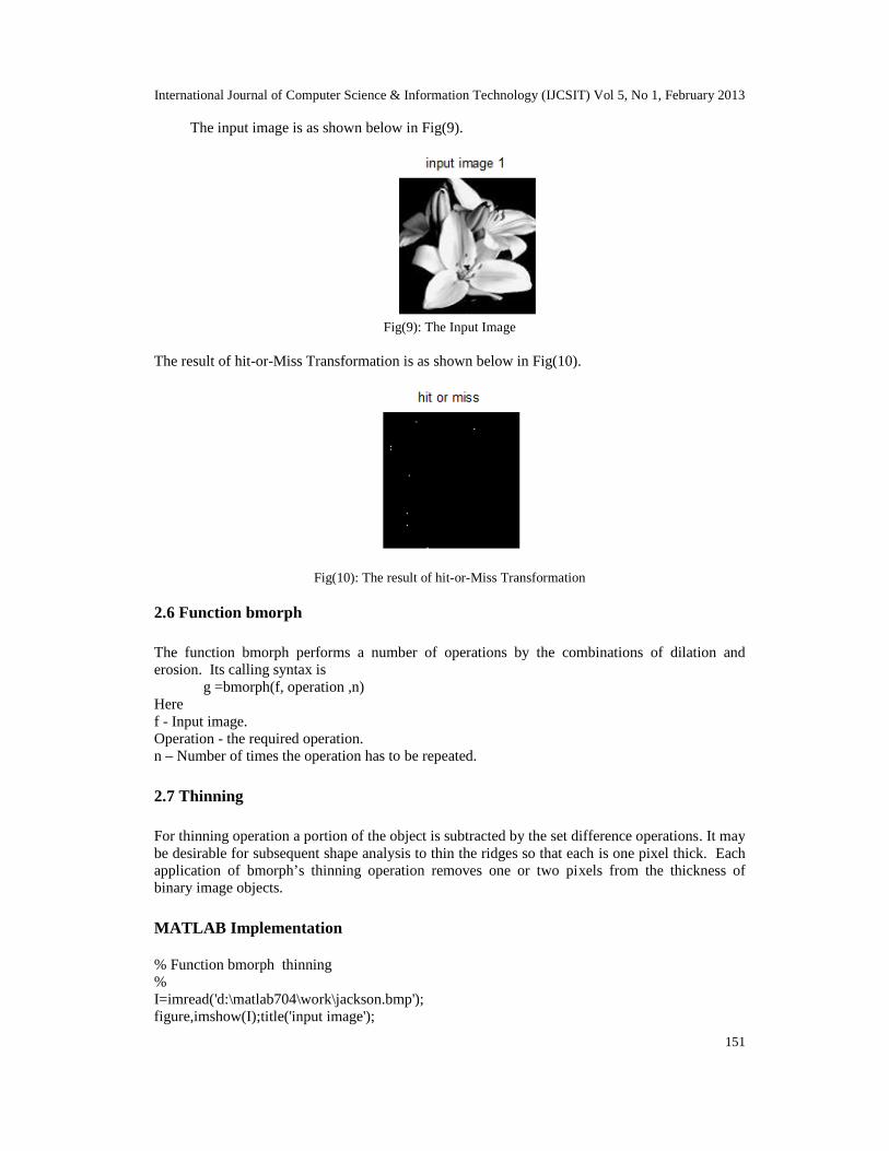
The input image is as shown below in Fig(9).
Fig(9): The Input Image
The result of hit-or-Miss Transformation is as shown below in Fig(10).
Fig(10): The result of hit-or-Miss Transformation
2.6 Function bmorph
The function bmorph performs a number of operations by the combinations of dilation anderosion. Its calling syntax is
g =bmorph(f, operation ,n)Heref - Input image.Operation - the required operation.n – Number of times the operation has to be repeated.
2.7 Thinning
For thinning operation a portion of the object is subtracted by the set difference operations. It maybe desirable for subsequent shape analysis to thin the ridges so that each is one pixel thick. Eachapplication of bmorph’s thinning operation removes one or two pixels from the thickness ofbinary image objects.
MATLAB Implementation
% Function bmorph thinning%I=imread('d:\matlab704\work\jackson.bmp');figure,imshow(I);title('input image');
International Journal of Computer Science & Information Technology (IJCSIT) Vol 5, No 1, February 2013
152
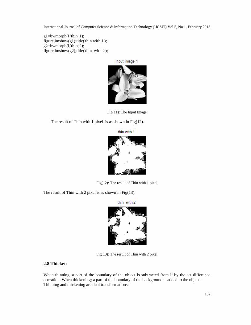
g1=bwmorph(I,'thin',1);figure,imshow(g1);title('thin with 1');g2=bwmorph(I,'thin',2);figure,imshow(g2);title('thin with 2');
Fig(11): The Input Image
The result of Thin with 1 pixel is as shown in Fig(12).
Fig(12): The result of Thin with 1 pixel
The result of Thin with 2 pixel is as shown in Fig(13).
Fig(13): The result of Thin with 2 pixel
2.8 Thicken
When thinning, a part of the boundary of the object is subtracted from it by the set differenceoperation. When thickening; a part of the boundary of the background is added to the object.Thinning and thickening are dual transformations:

International Journal of Computer Science & Information Technology (IJCSIT) Vol 5, No 1, February 2013
153
MATLAB Implementation
% Function bmorph thicken%I=imread('d:\matlab704\work\jackson.bmp');figure,imshow(I);title('input image 1');g1=bwmorph(I,'thicken',1);figure,imshow(g1);title('thicken with 1');g2=bwmorph(I,'thicken',2);figure,imshow(g2);title('thicken with 2');The result of Thicken of Fig(11) with1pixel is as shown in Fig(14) and the result of Thicken withpixel 2 is as shown in Fig(15).
Fig(14): The result of Thicken with 1 pixel
Fig(15): The result of Thicken with 2 pixel
3. GRAY-SCALE MORPHOLOGY
Binary morphological operations acting on binary images are easily extendible to gray-scaleimages using the ‘min’ and ‘max’ operations. Erosion(respectively, dilation) of an image is theoperation of assigning to each pixel the minimum(maximum) value found over a neighborhood ofthe corresponding pixel in the input image. The structuring element is richer than in the binarycase, where it gave only the neighborhood. In the gray scale case, the structuring element is afunction of two variables that specifies the desired local gray-level property. The value of thestructuring element is added (subtracted) when the maximum (or minimum) is calculated in theneighborhood.
The gray-scale dilation of f by structuring element b, denoted f(+)b, is defined as
(f(+)b)(x,y) = max{f(x-x’,y-y’)+b(x’,y’) Db}
Where Db is the domain of b.

International Journal of Computer Science & Information Technology (IJCSIT) Vol 5, No 1, February 2013
154
The gray-scale erosion of f by structuring element b, denoted f(-)b is defined as
(f(-)b)(x,y) = min{f(x+x’,y+y’)-b(x’,y’) Db}
Opening and closing
The opening of image f by structuring element b, denoted f ◦b is defined as
f ◦b = (f(-)b)(+)b
The closing of f by b, denoted f ● b is dilated followed by erosion:
f ● b =(f(+)b)(-)b
MATLAB Implementation
% Gray - scale morphologyI=imread('d:\matlab704\work\butterfly.bmp');figure,imshow(I);title('input image 1');se=strel('square',3);gd=imdilate(I,se);figure,imshow(gd),title('dialted image');ge=imerode(I,se);figure,imshow(ge),title('eroded image');morph_grad=imsubtract(gd,ge);I=imread('d:\matlab704\work\bubbles.jpg');figure,imshow(I);title('input image 2');se=strel('disk',5);fo=imopen(I,se);figure,imshow(fo),title('image opened')foc=imclose(fo,se);figure,imshow(foc),title('closing of opening')
The result of dilation of input image (16) as shown in Fig (17) and the result of erosion is shownin Fig (18).
Fig(16): The input image

International Journal of Computer Science & Information Technology (IJCSIT) Vol 5, No 1, February 2013
155
Fig(17): The result of gray scale dilation
Fig(18): The result of gray scale erosion
The result of opening of input image (19) as shown in Fig (20) and the result of closing is shownin Fig (21).
Fig(19): The input image
Fig(20): The result gray scale opening
International Journal of Computer Science & Information Technology (IJCSIT) Vol 5, No 1, February 2013
156
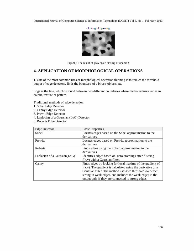
Fig(21): The result of gray scale closing of opening
4. APPLICATION OF MORPHOLOGICAL OPERATIONS
1. One of the most common uses of morphological operation thinning is to reduce the thresholdoutput of edge detectors, finds the boundary of a binary objects etc.
Edge is the line, which is found between two different boundaries where the boundaries varies incolour, texture or pattern.
Traditional methods of edge detection1. Sobel Edge Detector2. Canny Edge Detector3. Prewit Edge Detector4. Laplacian of a Gaussian (LoG) Detector5. Roberts Edge Detector
Edge Detector Basic PropertiesSobel Locates edges based on the Sobel approximation to the
derivatives.Prewitt Locates edges based on Prewitt approximation to the
derivatives.Roberts Finds edges using the Robert approximation to the
derivatives.Laplacian of a Gaussian(LoG) Identifies edges based on zero crossings after filtering
f(x,y) with a Gaussian filter.Canny Finds edges by looking for local maxima of the gradient of
f(x,y). The gradient is calculated using the derivative of aGaussian filter. The method uses two thresholds to detectstrong in weak edges, and includes the weak edges in theoutput only if they are connected to strong edges.
International Journal of Computer Science & Information Technology (IJCSIT) Vol 5, No 1, February 2013
157
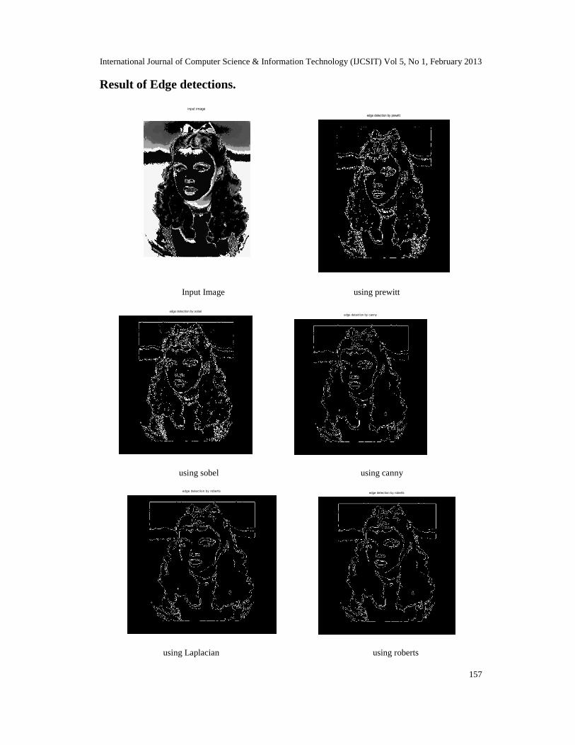
Result of Edge detections.
input image
edge detection by prewitt
Input Image using prewitt
edge detection by sobeledge detection by canny
using sobel using canny
edge detection by roberts edge detection by roberts
using Laplacian using roberts

International Journal of Computer Science & Information Technology (IJCSIT) Vol 5, No 1, February 2013
158
Result of Morphological Operations:Dilated image
erosion with d disk of radius 2
Dilated Image Eroted Image
thicken with 1thin with 1
Thin with one Thin with two
From this experiment we can say that mathematical morphology is the best method for edgedetection.
5. CONCLUSION
Mathematical Morphology is a powerful tool for examining shapes in pictures. It is powerful toolbecause of its ability to transform the structure of object with simple forms that enhances theirinterpretations. It is also very useful tool for extracting features from the images.
Some of the areas in which the morphologically extracted image features can be used are analysisof components of the images in the field of medical imaging, satellite images (Remote SensingImages), chemicals synthesis, industrial manufacturing of components, agriculture, artificialintelligence, neural networks etc.

International Journal of Computer Science & Information Technology (IJCSIT) Vol 5, No 1, February 2013
159
REFERENCES
[1] Digital Image Processing by Gonzalez and Woods, Pearson Education Asia.[2] Digital Image Processing Using MATLAP[2008] by Rafael C. Gonzalez, Richard E. Woods, Steven
L. Eddins, Pearson Education.[4] Fundamentals of Digital Image Processing, Anil K.Jain, Prentice-Hall of India Private Limited[2004].[5] Fundamentals of Image Processing by I.T. Young J.J. Gerbrands L.J. Van Vliet.[6] Digital Image Processing: Concepts, Algorithms, and Scientific Applications by[7] International Journal of information & knowledge management, July-2011, Volume 4.[8] CSI Communications Knowledge Digest for IT Community, July-2012, Volume 36.
AUTHOR BIOGRAPHY
Amalorpavam.G received MCA degree from Bharathidasan University, Tamil Nadu,India and M.Phil degree from Alagappa University, Tamil Nadu, India. Presented fourpapers in National level conference. Published a paper in National level Journal.Attended a workshop sponsored by AICTE. Attended a Seminar sponsored by NACCand attended five seminars. Presently working as an Assistant Professor at SambhramCollege, Bangalore, India.
Harish Naik T received MCA degree from Kuvempu University, Karnataka, India andM.Phil degree from Periyar University, Tamil Nadu, India. He has attended oneInternational Conference on Information Processing conducted at Bangalore. Presentedfour papers in National Conference .Attended two workshops sponsored by AICTE andattended 10 seminars. Presently he is working as an Assistant Professor at PresidencyCollege, Bangalore, India.
Jyoti Kumari received MCA degree from Bangalore University, Karnataka, India. Shehas attended a workshop sponsored by AICTE and attended four seminars. Alsopresented four papers in National level Conferences. Presently She is working as anAssistant Professor at Acharya Institution, Bangalore, India.
SURESHA M, received MCA degree from Kuvempu University, Karnataka, India,working as an Assistant Professor, Dept of computer Science, Jnana sahyadri,Kuvempu University, Karnataka, India.