analysis of flexible ehhhemhohhoie b2 eomhhhhohhhhhhenastran as his master'. thesis at afit....
TRANSCRIPT

'RD-R124 662 STATIC AEROELASTIC ANALYSIS OF FLEXIBLE MINOS VIANASTRRN PART IM)~ AIR FORCE INST OF TECHHRIGHT-PATTERSON AFB OH SCHOOL OF ENGINEERING K JONES
UNCLASSIFIED DEC B2 AFIT/GAE/AR/82D-ig-PT-i F/G 1/3 N
EhhhEmhohhoiEEomhhhhohhhhhhE

-I.
Iw
'ill 1j.2
* 11111125 LA11 1. I1.6ill1111 III - ln
MICROCOPY RESOLUTION TEST CHART- NATIONAL BUREAU OF STANDARDS-1963-A
• .,,, ~... -.-. .-.......... ,' -- -", .', -. - . " ". ..".-. • . .- .. . " '.- Z 'S 4 7 j -- - . ... .. .- . .. ".-,-

OF
U'; "ti!/ STATIC AEROELASTIC A NC -.SOF
FLEXIBLE WINGSVIA NASTRAN
hESIS
AFIT/GAE/AA/82D-16 Kim Jones1Lt USAk'" DTIC .
.;E
LE: -,,. FE S2 2 98
DEPARTMENT OF THE AIR FORCE-.- AIR UNIVERSITY (ATC)c5 AIR FORCE INSTITUTE OF TECHNOLOGY
-M-Wright-Patterson Air Force Bose, Ohio
IT h &, ::- . ,t has - . . c- r
k r

.-* . _ _ s' . ...- .- -,." . . ; <: -; .: -( ;: . '/ . L , - - - ' : . C ; : : : " ' '
AFIT/GAE/AA/82D-16
STATIC AEROELASTIC AN,%LY--;SOF
FLEXIBLE WINGSVIA NASTRALN
THESIS
AFIT/GAE/AA/82D-16 Kim JonesiLt USAF
?.
Approved for public release; distribution unlimitedl~ iOFT.
":,: FEXIBL WING
,6;!, VI 1AST3A

-. ~ ........ z..~sL~s*...- -7. .:,., ,,..,;..,.. ~~~.... _.. ........ ,........, .. ...... ...L.,, _ . ,. . ,. . . . . . . . . . .
AFIT/GAR/AA/8 2 D-16
STATIC AEROELASTIC ANALYSIS
OF
FLEXIBLE WINGS
VIA NASTRAN
PART I
THESIS
Presented to the Faculty of the School of Engineering
of the Air Force Institute of Technology
Air University
in Partial Fulfillment of the
Requirements for the Degree of
Master of ScienceAccession por,NTIS GRA&I
DTIC TAB
By Dtstr.b ,tiol
Kim Jones, B.S.A.E. Avajlrbi14 t Codes
lLt USAF Dist A mjo
Graduate Aerospace Engineering
December 1982
*l Approved for Public Release; Distribution Unlimited
o ° -,. -~ - .-, ., .* o-... -

Preface
This thesis is a continuation of the research done by
Captain Lance P. Chrisinger in his M.S. Thesis at AFIT in
1980. The first part contains the theoretical development
of the sequence along with the results of a survey of wing
models. The survey determined the characteristics of
average wing models that the procedure must be able to
tolerate. The second part develops a procedure for
designing and testing a NASTRAN module. Then the module
used for the aeroelastic sequence, GIAS, is used as an
example. The logical procedures in GIAS are then
explained. Finally, a detailed description of the
aeroelastic sequence is given along with a description of
how to implement it.
I would like to extend my gratitude to
Captain Hugh C. Briggs, who has understood and put up with
me while guiding me through this thesis.
I would also like to thank Michael Bernier and
Jim Trace for their help with the cor., u-L.r.
A very special thanks goes to my wife, Valerie, whose
patience and understanding has helped greatly with my stay
at AFIT.
ii:
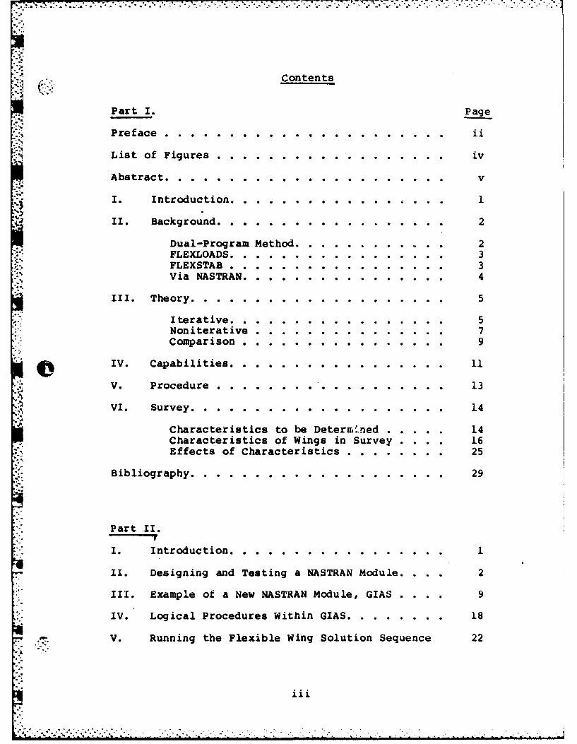
a Contents
Part I. Page
Preface . . . . . . . . . . . . . . . . . . . .
List of Figures . . . . . . . . . . . . . . . . . . iv
Abstract . . . . . . . . . . . . . . . . . . . . . . v
I. Introduction .................... 1
.. II. Background. . . . . .................. 2
Dual-Program Method .................. 2FLEXLOADS. . . . ................ 3FLEXSTAB . . ....... ........... 3Via NASTRAN. . . 4. ............ 4
III. Theory. . . . . .................... 5
Iterative. ............ . . 5Noniterative .. .............. 7Comparison . . . . . . . . 9
IV. Capabilities ................... 11
V. Procedure . ................. . 13
VI. Survey. . . . . . . . ........... 14
Characteristics to be Determ' ned ..... .. 14Characteristics of Wings in Survey . . .. 16Effects of Characteristics ......... 25
Bibliography. . . . . . . . . . . . ....... 29
Part II.
I. Introduction .... . . .......... 1
II. Designing and Testing a NASTRAN Module . ... 2
III. Example of a New NASTRAN Module, GIAS .... 9
IV. Logical Procedures Within GIAS .......... ... 18
V. Running the Flexible Wing Solution Sequence 22
iii
" - " . ... .. . . . . ' . .. . ' . - m . -- -- . "- ., , w a . -- ' - -
- - . , ]
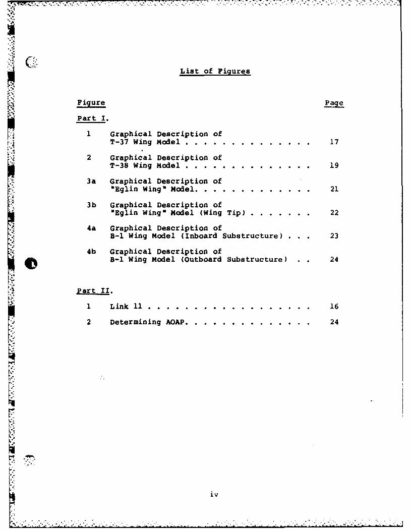
List of Figures
Figure Page
Part I.
1 Graphical Description ofT-37 Wing Model. .. .. ............ 17
2 Graphical Description ofT-Wig Woel. n g... .. d el.. 19
3a Graphical Description of*Egi ig e . . .U ..... 2
3b Graphical Description of"ElnWing" Model (Wing Tip) .. ........ 22
4a Graphical Description ofB-1 Wing Model (Inboard Substructure) . . . 23
4b Graphical Description ofB-i Wing Model (Outboard Substructure) .. 24
Part II.
2 Determining AQAP . . . . . . . . . . . . . . 24
iv

AFIT/GAE/AA/82D-16
Abstract
+3/
The purpose of this study was to expand theK capabilities of the Static Flexible Wing Aeroelastic
Sequence that-~Captain Lance P. Chrisinger developed for
NASTRAN as his Master'. Thesis at AFIT. Captain Chrisinger
developed a basic procedure to enable NASTRAN to analyze
flexible wing airloads and stresses. That capability is
expanded to enable analysis of standard wing models.
A subroutine was incorporated into NASTRAN to
eliminate extensive band-calculation of transformation
matrices.
IV
The capability to tolerate control surfaces was
discovered. Also, a survey of wing models in the Air Force
inventory was taken to determine the cuaacacteristics of the
average wing model. This was used to determine where the
aeroelastic procedure was lacking in its ability to analyze
wing models.
V
STATICAEROELASTIC ANALYSIS
OFFLEXIBLE WINGSVIA NASTRAN
PART I
I. Introduction
An improved aeroelastic package has been developed to
calculate stresses, displacements, and aerodynamic
coefficients for flexible wings undere-oing computer-
generated airloads. The package is based on the readily
available NASTRAN computer program and can tolerate
moderately complex wing models with secondary structure.
The need for such a package became evident as aircraft
wings were designed with more structural flexibility. The
changes in displacements caused by the airloads, and the
changes in airloads caused by the displacements became
significant enough to warrant attention. As a result,
several aeroelastic analysis packages have been designed,
such as FLEXLOADS and FLEXSTAB. However, all of the
packages designed so far contain deficiencies that prevent
them from efficiently solving complex wing structures.
This package is an attempt to design an aeroelastic
analysis program that does not have any serious drawbacks.
-4
....................... . ...

II. Background
The aeroelastic flexible wing problem is a study in
fluid-structure interaction because the airloads on the
structure are dependent on the displacements of the
structure. Several packages have been designed to solve
this interaction problem for aircraft wings.
Dual-Program Method
One type of solution technique uses an airloads
generator computer program and a structural analysis
package. The advantage of this method is that its parts
are already in existence. However, there are some serious
drawbacks to this solution technique. Much time is
consumed in transforming the generated airloads into forces
for the structural analysis package. Also, the
displacements from the structural analysis package must be
transformed into displacements for the airload generator.
An additional problem with this method is the duplicate
computer work required. As iterative passes are made
through the airloads generator and structural analysis
package the same equations are assembled and decomposed.
This results in the same work being done with each pass
through the system.
2 .. ..!. .

FLEXLOADS
Another solution technique aimed at solving the
. flexible wing problem involves a single program using an
iterative solution. The program, FLEXLOADS, was developed
by General Dynamics where it is currently being used to
analyze several bombers and transports. They are also
modifying FLEXLOADS to use with nonlinear aero theory in
order to investigate the separation and stall flight
I.I regimes. Northrup is using FLEXLOADS in their analysis of
L. several fighters. The advantages of FLEXLOADS are that it
is a relatively small, easily manageaLile program and that
it contains several different aero theories to choose from.
A disadvantage is its size restriction of 165 degrees-of-
freedom (DOF), which will limit the complexity of the
models that can be analyzed. An attempt is being made at
San Antonio Air Logistics Center (SAALC) to use Guyan
Reduction to reduce the number of DOF of a T-37 wing model
from 850 to 165 DOF and still keep its accuracy. They are
currently having difficulty finding a representative set of
nodes that leaves the natural frequencies and static
displacements unaltered.
FLEXSTAB
Still another way to solve the flexible wing problem
is to use FLEXSTAB, a computer program developed by Boeing.
FLEXSTAB was originally designed as a stability analysis
package but can also analyze structures. It is currently
being used at Nasa-Dryden an Nasa-v igley. The primary
3. --. . . . . .
disadvantage of FLEXSTAB is that it gives only
approximations of the stresses and displacements because it
uses equivalent beam elements rather than the detailed
model.
Via NASTRAN
Captain Lance Chrisinger, in his Master's Thesis at
AFIT, had previously done all the preliminary work of
comparing these various solution techniques (Ref 3). The
problems a solution technique must be able to tolerate in
order to effectively solve a flexible wing are: a wide
variety of element types, any odd characteristics of
typical wing models such as node number resequencing
(SEQGP) cards, and large numbers of elements. After
looking at these requirements and the characteristics of
all the available solution techniques it became apparent
that there is a need for yet another solution technique.
The s-'ution technique must involve a complete, self-
contained computer program. All of these qualities were
-found in the NASTRAN computer program. The one
disadvantage that this program does have is that it is
rather large and unwieldy. However, with the recent
inclusion of an airload generator, NASTRAN has all the
requirements to effectively solve a flexible wing. In
addition, Captain Chrisinger built an instruction sequence
for solving the flexible wing problem for a simple generic
wing box (Ref 3).
4
b-7-
III. Theory
There are two approaches to solving flexible wings.
Both are based on the same assumptions but differ in
methodology. In one scheme iterative passes are made
through a sequence of steps while in the other the process
is assembled into a single equation to be solved (Ref 2).
Iterative
The iterative solution consists of three parts: a
pre-processor to set up the operations, an iterative loop
that terminates when a specified tolerance is reached, and
a post-processor to recover the output.
Definitions
* -* general matrix multiplier
Us the change in structural deformation
(the first value is the initial structural
displacements representing the initial
angle-of-attack)
IUw, - The cumulative structural deformation
Q - The change in forces on the structural
grid
- The cumulative forces on the structuralI:'2rgrid
- The changes in airloaWd on the aero grid
Q - The cumulative airloads on the aero grid
5

Procedure
set U. = Angle of Attack ini. angle of
set Ur = - Angle of Attack attack so the
initial angle of
attack will not be
included in summing
the deformations
set Q = 0
set QT = 0
top of loop
UA = G * Us G - transformation
matrix from struc-
tural displacements
to aero displace-
ments
Q, = A * UA A - matrix of aero
coefficients
"" G G* - transformation
matrix from airloads
on aero grid to
forces on structural
grid
U - * Q K - stiffness matrix
U, L. + U6 cumulating structur-
al deformation
changes
6",o -- - -. . -

S Q + Q cumulating changes
in forces on struc-
tural grid
QA= OAT +Q1 cumulating changes
in airloads on aero
grid
go to top of loop unless the norm of the change
" - in structural displacements is less than
the tolerance
output
Usr
Qs-
aerodynamic coefficients
Noniterative
The noniterative scheme uses the same assumptions
but it is ordered differently (Ref 2):
Definitions
* - general matrix multiplier
K - the stiffness matrix
Us - structural deformations
O'- structural forces
G - the transformation from aero forces to
structural forces and also from structural
deformations to aero deformations
AOA - initial angle of attack
U4 - aero deformations
4 7
-aero forces()A -cofiinsoaeofrs
CPA - coefficients of aero presue
DlJK - matrix of aero coefficients, real
part of complex aero wash
D2JK -matrix of aero coefficients, imtaginary
part of complex aero wash
A=. matrix of aero influence coefficients
SKJ -matrix of areas of the wing
Q -dynamic pressure
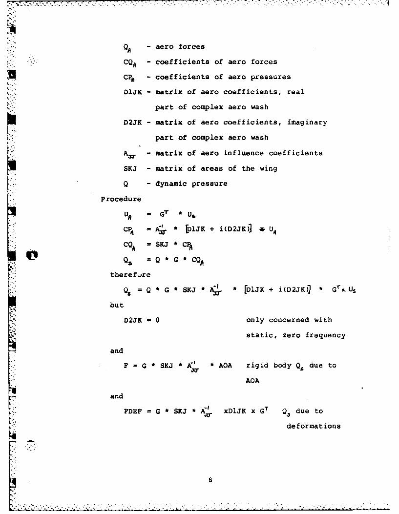
Procedure
CP A j.* lJK + i(D2JK)) U4
CQ4 =SKJ CPA
therefore
Q5 Q G SKJ A k [DJK +i (D2JK)j* Gr% U.,
but
D2JK -0 only concerned with
static, zero frequency
and
F -G *SKJ * AOA rigid bodyQ., due to
AQA
- and
FDEF G*SKJ*A' xD1JK xG T Q due to
deformations
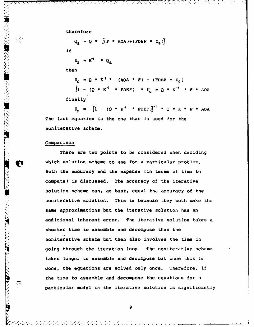
there fore
'Q - Q * [(F * AOA)+(FDEF * US)]
*if.:.:"'-'U 5 -KIC * Q.
then
U, - Q * K 1 * (AOA * F) + (FDSF * US)
'1- (Q * K' * FDEF) * U --Q * K" * F * AOA
finally
U. K l(Q,-I' FDEF)' *Q*K *F *AOA
The last equation is the one that is used for the
noniterative scheme.
- Comparison
There are two points to be considered when deciding
which solution scheme to use for a particular problem.
Both the accuracy and the expense (in terms of time to
compute) is discussed. The accuracy of the iterative
solution scheme can, at best, equal the accuracy of the
noniterative solution. This is because they both make the
same approximations but the iterative solution has an
additional inherent error. The iterative solution takes a
shorter time to assemble and decompose than the
noniterative scheme but then also involves the time in
going through the iteration loop. The noniterative scheme
takes longer to assemble and decompose but once this is
done, the equations are solved only once. Therefore, it
the time to assemble and decompose the equations for a
* particular model in the iterative solution is significantly
9-o . .. . . . . b . . .

shorter than that for the noniterative solution, then the
iterative solution will take less time. In order for this
Ali to work, the assembly and decomposition time for the
iterative solution has to be shorter than the noniterative
solution by the amount of time it takes for the iterative
solution to complete all the iterative passes. Recent
experience indicates typically 3-6 passes are required for
simple models. For the present work, the iterative scheme
'A has been employed.
10
I .'. .

F--.
IV. Capabilities
The discussion of the capabilities of the current
solution technique is broken into two parts. The first
gives an outline of the applicable characteristics of
NASTRAN. The second describes the capabilities of the
instruction sequence.
As outlined in the background section, the primary
disadvantage in using a program such as NASTRAN is its
large size. Because of this the instruction sequence is
more difficult to manipulate. Another disadvantage is that
NASTRAN uses only one aero theory, a Doublet-Lattice
Method. This theory does not generate any rotational
forces; therefore, any bending elements in the model will
not have forces along their rotational DOF due to the
airloads. Despite these disadvantages, NASTRAN was chosen
as a host program because of its several advantages. The
most important of these is NASTRAN's ability to tolerate
very large problems efficiently. Anot.ner major advantage
is the wide variety of element types already available in
NASTRAN. In addition, many options to the instruction
sequence are easily implemented. These three advantages
lend a great deal of flexibility to any instruction
. .

sequence implemented with NASTRAN. This is essential when
S"'dealing with the wide range and variety of wing
characteristics encountered.
This second section outlines the capabilities of the
instruction sequence. The ultimate goal for the sequence
is to be able to solve for the stres -tt, displacements, and
aerodynamic coefficients of an entire flexible aircraft.
Currently, a restricted type of flexible wing can beN solved. Provisions have been made to calculate internally
all of the transformation matrices and other derived input
data. This enables the user to analyze a wing using an
existing model with minimum additional input data. The
instruction sequence is capable of solving deflected
control surfaces as long as the deflections are small
enough to stay within linear aero theory. Substructuring
has not been attempted while using the instruction
sequence. The only wing surface element type that can be
used by the instruction sequence is the CQDMEM2 element.
Provisions have yet to be made to tolerate grid point
number resequencing (SEQGP) cards. Wing-fuselage
aerodynamic interaction can be modeled by constructing an
aero model of the fuselage near the wing root.
12
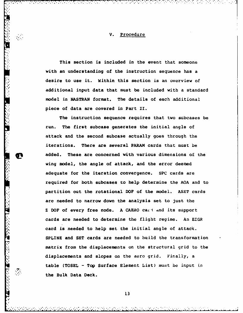
V. Procedure
This section is included in the event that someone
with an understanding of the instruction sequence has a
desire to use it. Within this section is an overview of
additional input data that must be included with a standard
model in NASTRAN format. The details of each additional
piece of data are covered in Part II.
The instruction sequence requires that two subcases be
run. The first subcase generates the initial angle of
attack and the second subcase actually goes through the
iterations. There are several PARAM cards that must be
added. These are concerned with various dimensions of the
wing model, the angle of attack, and the error deemed
adequate for the iteration convergence. SPC cards are
required for both subcases to help determine the AOA and to
partition out the rotational DOF of the model. ASET cards
are needed to narrow down the analysis set to just the
Z DOF of every free node. A CAERO ca± i and its support
cards are needed to determine the flight regime. An EIGR
card is needed to help set the initial angle of attack.
SPLINE and SET cards are needed to build the transformation
matrix from the displacements on the structural grid to the
displacements and slopes on the aero grid. Finally, a
table (TOSEL - Top Surface Element List) must be input in
the Bulk Data Deck.
13. . . . . . . . . . . .

VI. Survey
In order for the instruction sequence to run
efficiently with standard wing models their characteristics
must be known. To this effect a survey of several wing
models in the Air Force inventory was taken. The answers
to a list of questions were compiled to determine the
characteristics of the average wing model. Though several
wings were surveyed, only four will be presented here.
These depict typical wing models. The rest are not
presented because of repetition.
(Characteristics to be Determined
The characteristics investigated were:
1. The number of grid points and DOF. This is an
estimate of the size of a typical wing model.
2. Whether the model has leading and/or trailing edge
secondary structure. Since the aero and
structural models should both have the same
planforms structural models without the secondary
structure will require modification.
3. If the model has been validated with only the
Z-DOF in the analysis set. The inodel1 can be
S.. validated either by known static deformations or
by known natural frequencies. This should have
14

been done because the current NASTRAN aero
theories allow only the Z-Do-' in the analysis
.. set (Ref 1).
4. The existence of any stresses, displacements,
basic aerodynamic coefficients, and distri-
butions for flight test data and standard
computer analysis. This provides a measurement
standard for judging the accuracy of results.
Computed versions of these items can be generated
by the solution sequence to provide accuracy
checks at various points in ':he sequence. The
data from a standard computer analysis could be
used to check the sequence before it enters the
iterative loop. The flight test data provides a
check for the final results from the solution
sequence.
5. Types of area elements on the wing surface.
Currently, only certain element types on the wing
surface can be analyzed by the solution sequence.
6. If there are any bending elements in the model.
This will affect the validation described in
question 3 since the analysis set for the solution
sequence is condensed to only translational DOF
by Guyan reduction.
7. If there are any SEQGP cards. This would affect
the internal equation numbering which in turn
affects the calculation of some of the transforma-
tion matrices (Ref 1).
15

8. If the wing model includes wheel wells or other
cutouts. This will become significant when aero
theories are implemented that panel 3-D
structures. The current theory uses 2-D lifting
" surfaces and is only affected by the curvature of
mean camber surface (Ref 1).
9. Is it in NASTRAN format. Considerable time and
money can be spent in reformatting data to NASTRAN
format.
Characteristics of Wings in Survey
Several wing models were evaluated with respect to the
criteria. These models are T-37, T-38, B-l, C-5, and
KC-135. Also, a wing model termed the "Eglin Wing" was
C included in the survey. The four win,7s presented in detail
are the T-37 wing, the T-38 wing, the uglin Wing," and the
B-i wing.
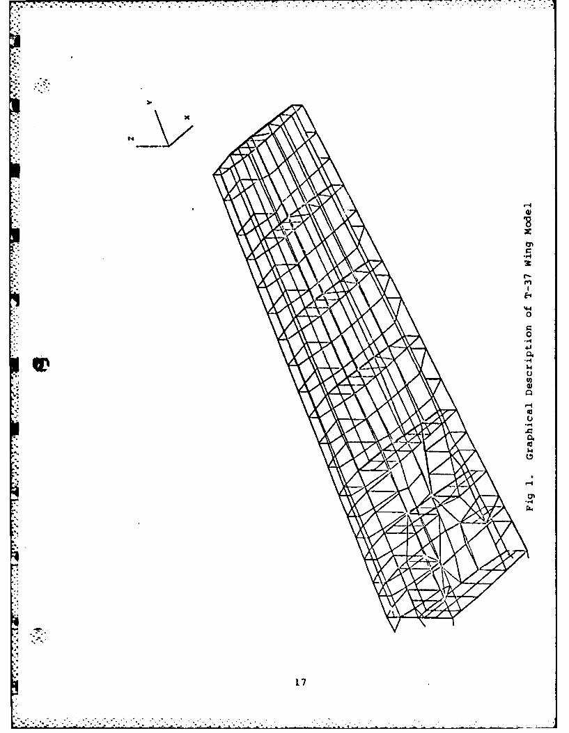
The T-37 is illustrated here because it is a typical
early subsonic wing type (Fig 1). It only has two spars
and a thin skin. Unlike modern fighters, the T-37 wing has
a high aspect ratio and a complex wing carry-through
connected to the fuselage. This carry-through will present
some problems in determining the wing root boundary
conditions for this type of wing. The T-37 wing model has
319 grid points with 850 DOF. The model has no leading or
trailing edges and, therefore, no control surfaces. This
particular wing model has been validated in the Z-DOF only.
' "This is unusual, typically wing models contain rotational
16
117
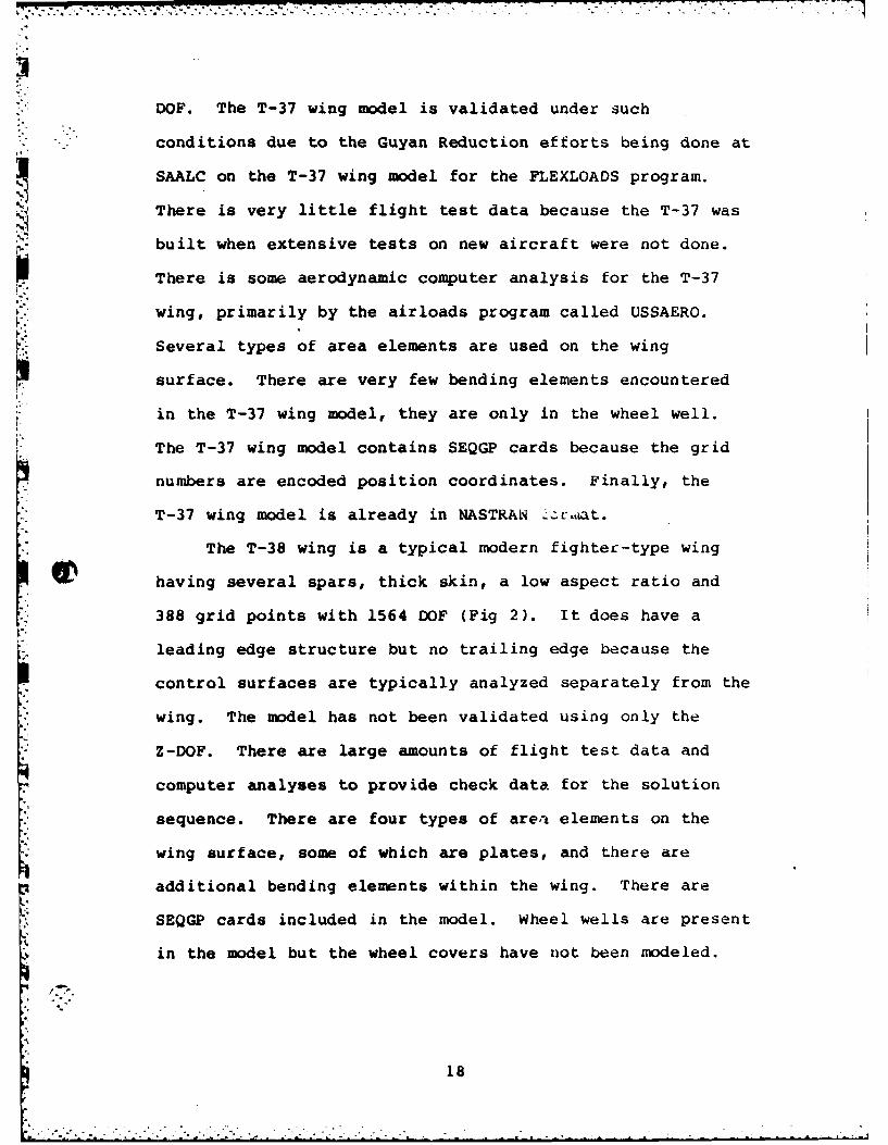
DOF. The T-37 wing model is validated under such
S"-. conditions due to the Guyan Reduction efforts being done at
SAALC on the T-37 wing model for the FLEXLOADS program.
There is very little flight test data because the T-37 was
built when extensive tests on new aircraft were not done.
[I There is some aerodynamic computer analysis for the T-37
wing, primarily by the airloads program called USSAERO.
Several types of area elements are used on the wing
surface. There are very few bending elements encountered
in the T-37 wing model, they are only in the wheel well.
The T-37 wing model contains SEQGP cards because the grid
numbers are encoded position coordinates. Finally, the
T-37 wing model is already in NASTRAN - r,,at.
The T-38 wing is a typical modern fighter-type wing
having several spars, thick skin, a low aspect ratio and
388 grid points with 1564 DOF (Fig 2). It does have a
leading edge structure but no trailing edge because the
control surfaces are typically analyzed separately from the
wing. The model has not been validated using only the
Z-DOF. There are large amounts of flight test data and
computer analyses to provide check data for the solution
sequence. There are four types of area elements on the
wing surface, some of which are plates, and there are
additional bending elements within the wing. There are
SEQGP cards included in the model. Wheel wells are present
in the model but the wheel covers have not been modeled.
18

-40
-4
04
C
190

Analyzing the wing is simplified by the fact that it is in
NASTRAN format and has been analyzed in several static load
conditions.
The Eglin Wing is presented because it is a typical
damage tolerance wing model (Fig 3). These tend to be more
complex because they have to closely trace the stresses
throughout the wing. As a result, the Eglin Wing has 542
grid points with 2710 DOF. The model has both leading and
trailing edges, the trailing edge consists partly of the
control surfaces. It has not been validated with only the
Z-DOF. The check data available is a minimum with only a
small amount of computer analysis pro.'ided. There are
several types of area elements on the wing surface in both
triangular and quadrilateral shapes. The Eglin Wing does
have bending elements. A large number of SEQGP cards are
present which will affect the transformation matrices. The
model also contains wheel well cutouts whose covers will
have to be modeled if a 3-D aero theory is implemented. As
with the T-38 wing model, the Eglin Wing is also in NASTRAN
format and has been run in several static load cases.
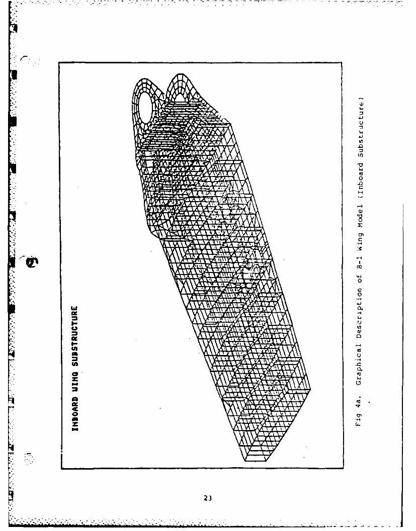
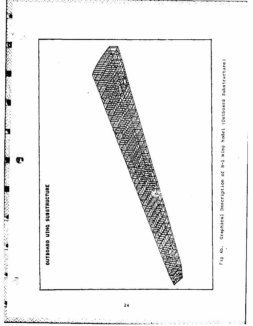
Despite the effects of the wing pivot area, the B-1
wing model is taken as a typical "heavy-aircraft" type
wing. These effects do not interfere with the present
analysis so swing wing aircraft can also be analyzed. The
outboard sections of the wing are fairly typical to other
"heavy-aircraft" wings. Because the wing is large and
complex, there are a great number of grid points and DOF,
5116 grid points with 24,361 DOF (Fig 4). Fortunately,
20

-4A
IINI 0
04
'-40
QM
21"

r-4
0'
0'4-
p-4
4
U)
22)
k4-
.0
Ub)
C9C
230
w 'I
4'0zL
c'a
240

wings of this size can be analyzed using substructuring.
S -. The largest substructure in the B-i wing model has 1605
grid points and 5479 DOF. This is sti.l large but it is
much more manageable than the entire wing. All parts of
the wing are represented by the substructuring, including
the leading and trailing edges, with the control surfaces.
The B-I wing model has not been validated using only the
Z-DOF. There has been a lot of flight test data and
computer analysis done on the B-1 wing. There are four
types of area elements on the wing surface. The model
includes bending elements, but no wheel wells or other
cutouts. Since the B-i model is not in NASTRAN format,
SEQGP cards are not applicable.
Effects of Characteristics
Considering the wide range of characteristics of the
wings in the survey, it is evident that compromises must be
made. While the overriding concern in designing the
solution sequence is to make it user-oriented, it is not
possible to design the sequence for every characteristic.
At times certain models will have to be altered to fit the
sequence. The average size of wing models is fairly large
and requires the sequence to use computer space
efficiently. However, after the usage has been trimmed
down as far as possible, there will still be some wing
models that will be too large for the computer used. In
these cases, either substructuring should be used or the
complexity of the model lessened by Guyan Reduction
25*.. . . . . . . . .".%.

techniques.
If the structural wing model does not have leading
and/or trailing edges, then two courses of action can be
taken. One method is to alter the solution sequence to
artificially transfer the loads from the leading and
trailing edges to the structural wing box. However, this
requires large amounts of the user's time. The second
course of action would be to put leading edges on the wing
model. This is the easier of the two in that, once done,
--it automates the load transfer from the edges to the wing
.box.
Since most wing models are not validated in the Z-DOF,
there will be some error in using these models. The error
can be measured by restricting the model to the Z-DOF,
performing the validation procedures, and calculating how
far off the model with only Z-DOF is from the actual
structure. If the error determined is unacceptable, the
model should be adjusted to give accurate values in the
Z-DOF. Another course of action can be taken to reduce the
error but it requires extensive rebuilding of the solution
sequence. The only reason the models put through the
solution sequence are reduced to Z-DOF is the aero analysis
within the sequence cannot tolerate any displacements
except out-of-plane translations. If desired, a different
aero theory can be implemented into the solution sequence
but it would require many months of effort to rebuild and
4debug the altered solution sequence.
Most wing models only use three or four area element
26
r. types on the wing surface. Given these element types, no
problem is encountered with the solution sequence.
However, if an element type different from those normally
L. used is put on the wing surface then problems can arise.
It is a simple matter to add that element type to the
capabilities of the solution sequence, if sufficient
knowledge of how the solution sequence works is available.
LacKing that, it is advisable not to include the new
element type in the wing surface.
* •Virtually every wing model contains bending elements.
As with the validation of the models in the Z-DOF, the
restriction of using bending elements in the solution
sequence lies within the aero model. The bending elements
will not be loaded by the aero forces in the rotational
DOF. If the error incurred is unacceptable the recommended
solutions are the same, either replace the bending elements
or implement a different aero theory.
Most of the large wing models contain SEQGP cards in
an effort to improve the bandwidth of the matrices
involved. Currently there is no capability to tolerate
SEQGP cards in the solution sequence so care should be
taken in choosing the form of the input data for the wing
model.
Most wing models contain wheel wells or other cutouts.
This is not a problem with the present aero theory but it
will need to be considered if a different aero theory is
implemented. The most obvious solution is to include the
wheel covers in the model. This will ailow the wheel well
27
.. .. ... .

.', --
doors to be included as part of the lower wing surface.
A problem not previously mentioned is the aerodynamic
interaction between the wing and other aircraft structures.
If the wing is modeled alone then these effects are not
taken into account. The aircraft structure that most
Icommonly interacts with the wing is the fuselage. If the
F fuselage tends to be flat and vertical at the wing root,
then the centerline symmetry condition of the wing alone
will be a reasonable approximation. However, if the
'fuselage-wing root structure is rounded and smooth then
there can be a great deal of crossflow. Other structures,
such as engine inlets, engine exhaust, and winq mounted
stores, can also affect the airflow across the wing.
Wing-fuselage aerodynamic interaction can be modelled by
constructing an aero model of the fuselage near the wing
root.
The solution sequence can tolerate most of the
characteristics of the average wing model. However,
further revisions to the sequence would broaden its
capabilities and applicability.
28
* Bibliography
*1. NASA SP-222(04). The NASTRAN User's Manual (Level17.0). National Aeronautics a-nd Space Administraion,December 1979.
2. Ford, Douglas A., Advanced Development Projects,Lockheed Aircraft Corporation (Personal Interview).Lockheed, California, October 21, 1982.
3. Chrisinger, Lance E. Calculation of Airloads for a* Flexible Wing via NASTRAN. M.S. Thesis.
DTIC AD A094770, Wright-Patterson AFB, Ohio:Air Force Institute of Technology, December 1980.
29

AFIT/GAE/AA/82D-16
STATIC AEROELASTIC ANALYSIS
OF
FLEXIBLE WINGS
VIA HASTRAN
PART II
'-ESIS
Presented to the Faculty of the School of Engineering
of the Air Force Institute of Technology
Air University
in Partial Fulfillment of the
Requirements for the Degree of
Master of Science
By
Kim Jones, B.S.A.E.
lLt USAF
Graduate Aerospace Engineering
December 1982
Approved for Public Release; Distribution Unlimited
* . -,

S.-Contents
Part I. Page
I. Introduction ... . ........ . 1
Ii. Background. . . . . . . ............. 2
III. Theory. . . . . . . . . . .................... 5
IV. Capabilities. . . . . . . ........ . 11
V. Procedure . . . . . . ........... . 13
VI. Survey. . . . . . . . . ............ 14
Part II.
Abstract. . . . . . . . . . ............ iiI. Introduction. . . . . ................
II. Designing and Testing a NASTRAN module . 2
III. Example of a New NASTRAN Module, GIAS . . .. 9
IV. Logical Procedures Within GIAS .......... ... 18
Output Datablocks. . . . . ......... 18Logical Procedures . . . . ........... 19
V. Running the Flexible Wing Solution Sequence 22
Logical Procedures . . ............ 22Implementation . ................ .... 26
SBibliography . .. .. .. .. .. .. .. .. . .. 31iVita . . . . . . . . . . . . . . . . . . . . . . . 32•
Appendix A: GIAS and Environment ............ 33
Appendix B: Sample Input Data and Illustration . . 79
I.
|--i

AFIT/GAE/AA/82D-16
Abstract
This thesis is a continuation of the research done by
Captain Lance P. Chrisinger in his M.S. Thesis at AFIT in
1980. Captain Chrisinger developed a basic procedure to
enable NASTRAN to analyze flexible wing airloads and
stresses. That capability is expanded in this report to
enable analysis of standard wing modeis.
A subroutine was incorporated into NASTRAN to
eliminate extensive hand-calculation of transformation
matrices.
The capability to tolerate control surfaces was
discovered. Also, a survey of wing models in the Air Force
inventory was taken to determine the characteristics of the
average wing model. This was used to determine where the
aeroelastic procedure was lacking in its ability to analyze
wing models.
~iii
m" ' m "I m' u --":,, . , # --- . ..h.-,.. . .. .

i -STATICAEROELASTIC ANALYSIS
OFFLEXIBLE WINGSVIA NASTRAN
PART II
I. Introduction
This part presents a detailed account of the
procedures associated with the NASTRAN instruction sequence
for flexible wings. However, the presentation presumes a
level of knowledge about NASTRAN and its organization. In
order to fully understand the majority of this part, the
reader must understand the organization of NASTRAN, to
include datablocks, modules, links, and overlays. The
reader should have taken, or have notes of, a course
dealing with NASTRAN System Programming (Refs 3,4).
This part is organized into three sections. The first
two describe a recommended procedure for designing and
testing a module to be put inside NASTRAN. This will also
include, as an example, the module designed to work within
the NASTRAN instruction sequence to solve flexible wing
problems. These two sections were included to illustrate a
set of steps not given elsewhere on designing and testing a
NASTRAN module. The third section in this part is a
detailed account of how to run this instruction sequence,
with an explanation of additions to tiU. liulk Data Deck.° 9.°

II. Designing and Testing a NASTRAN Module
The following is a recommended procedure for designing
and testing new NASTRAN modules. The procedure carries
through from the initial conception of the need for a new
module to the final testing of the module once it is inside
NASTRAN. The procedure pulls together information from
various NASTRAN publications to preseiL complete, logical
sequence of steps to design and implement a module. These
steps are designed to insure the most error free module in
the least amount of time. These will minimize the
debugging required while manipulating the entire NASTRAN
0? package. To do this the module must be tested in an
environment as close to NASTRAN as possible before the
module is entered into NASTRAN. The recommended steps in
designing and testing a NASTRAN module are:
1. Recognition of the Need. In designing a new
DMAP sequence or running an extensive DMAP
alter the user might recognize that none of the
DMAP statements, nor any combination of them,
provide him with a procedure he needs.
The first thing he must do before considering
adding a module is be sure that there is no other
way to accomplish the procedure, even by a round-
S..about method. The time and effort required to
2

design, test, and implement a new NASTRAN module
is enough to make it a last resort. If it is at
. all reasonable to operate without the module then
that course of action is recommended. In con-
sidering a DMAP to solve his problem the user
might compare MSC NASTRAN to COSMIC NASTRAN.
The MSC version contains many more modules
and might have the proper DMAP modules where
the COSMIC version did not.
2. Development of the logic process and recognition
of required inputs. These two steps are lumped
together because the logic processes inside the
module must operate within the NASTRAN
environment. Some of the inputs that would be
ideal for the procedure might just not be
there, or might exist but in a format that
will increase the complexity of the
module's logic. To determine exactly what
is needed by the sequence from the module,
and also to check the sequence, run the sequence
with the module and its outputs replaced by hand-
generated data.
3. Determine where to get the inputs.
There are several ways that inputs are available
to a module. They can either be: an existing
datablock, a datablock that can be built in the
3

DMAP before the module is executed using DMAP al-
ters or the data that can be user supplied through
PARAM, DTI, or DMI cards. Datablocks can be
either matrices or tables. The way the data
reaches the module will have an effect on its
logic processes and on the amount of user input
needed. It is desirable to require as little as
possible from the user. This will reduce input
errors.
4. Write the module with all of its NASTRAN-
necessary parts. NASTRAN uses the Fortran IV
computer language. Any limitations with this
language must be taken into account when writing
the module. The module will be operating in an
tP environment with common staLCi,. nts, open core
arrangements, and various other subroutines
to which it has access. Depending on. the
design of the module, the use of these will
have to be carefully planned out so as to
minimize the module's use of computer time and
. space. This must be considered because the large
variation of problem types encountered will cause
the solution sequence to tax the capabilities of
most any computer.
5. Build a file of the data the module will receive.
*" This will be the input to a simulated environment
built to debug the module as thoroughly as
4

I 1Apossible before it is put inside NASTRAN. The
content of the data should be from several sample
cases to which the correct (or at least expected)
answers are known. The form of the data can be
up to the user but it should contain all the
information that will reach the module, not just
what the module will use. The procedures to
develop this file are determined by how the
module will get the data when it is incorporated
into NASTRAN. To get the data that the user will
supply to the module when it is incorporated into
NASTRAN is relatively simple. Just put the data
on the input file as it would appear in the Bulk
Data Deck. The other data, those that are gener-
ated inside NASTRAN before the module, will
require a different approach. A solution
sequence nearly identical to the one that will
use the module should be run. This solution
sequence should not have the call to the module
being developed. It is not necessary for the
sequence to run until completion. All that is
required is to derive the data that the module
will use. This data should be punched out of a
NASTRAN run onto a file. It is advisable to do
this right after the last DMAP statement before
the new module is called. It is easier to do
this with a DMAP alter. The specific cards that
5.= .- . . .

- --. .. . . .. .. .- .. -. -i " : - -'' .. . /'i : ' - " - * 1
need to be inserted in the DMAP depends on the
form of the data. If the data is in table
format use the TABPCH module. If it is in
matrix format use MATPUN.
6. Build environment around the module to simulate
the NASTRAN environment. Ideally, this
should be done with as few changes to
the module as possible. The form of the
module should be as close as possible to the form
it will have when inside NASTRAN. The environ-
ment should consist of several subroutines,
including the module, with a master sequence of
commands whose job it will be to call an ini-
tialization subroutine and ttei, the module.
The module, in turn, will call utility sub-
routines. The environment should simulate all
the common statements, open core, functions, and
subroutines that the module will see while
inside NASTRAN. The environment subroutines
need not do exactly what the equivalent NASTRAN
subroutines do, but they must return the same
response to the module. Some of the subroutines
the module calls may hare to be copied from
NASTRAN source code and put into the environment
rather than just building similar ones. How-
ever, caution should be used in doing this
because the subroutines pulled from NASTRAN will
6

have to have their NASTRAN environments simu-
lated also. Their environments can be as simple
as another utility subroutine or they can require
an assortment of common statements, open core,
functions, and subroutines of their own.
7. Run several test cases to debug the module in the
environment. The test cases should use the input
data described in Step 5. It is helpful here to
put internal check statements within the environ-
ment. Perhaps printing out a simple statement
telling which subroutine the program is in. The
module must be debugged until the environment's
output data is exactly what the user wants NASTRAN
to see once it finishes executing the module.
8. Put the module inside NASTRAN.
The procedure to do this can be found in the
NASTRAN Programmer's Manual, in most any other
NASTRAN system programming text or from someone
who has done it before and i; knowledgeable
about the NASTRAN system. The module must be
put in a link that will allow it access to the
subroutines and common areas the module needs.
9. Run additional tests on installed module until
satisfied. These should begin with the same test
cases run before, in Step 7. However, it might be
a good idea to run additional cases. It could be
helpful to have various matrices and tables
7
. . . . .. . . .. . . . . . . . . . .

printed out at key locations within the DMA.P. Of
* - course, to run these cases, the trial DMAP should
have been altered to include the call for the
module.
ia
'.. .....

III. Example of a New NASTRAN Module, GIAS
This section uses the NASTRAN module GIAS as an
example of the procedure to design a module.
GIAS was designed to build various matrices used to
solve the flexible wing problem. Beforehand, the matrices
were manually calculated and entered into the program via
DMI cards. The overriding concept in GIAS is to minimize
the. work the user must do. As many matrices as possible
are built within GIAS. This leaves only one matrix, other
than the normal model data, to be built by hand. As
development on GIAS continues, this matrix will also be
g built inside NASTRAN.
The following is a reiteration of the steps necessary
to design a module for NASTRAN, with specific application
to GIAS.
1. Recognition of need. The solution sequence for
solving flexible wings requires several transfor-
mation matrices and moment arm vectors. The
procedure used to generate these matrices is much
too detailed and complex for NASTRAN to accomplish
it with DMAP. Therefore, in order to signifi-
cantly reduce the amount of udLa to be entered by
the user a new module is needed to calculate the
extra data.
.... .....

2&3. Development of logic process, recognition of
required inputs and where to get them. Since the
object of the module is to reduce the user's work
most of the input data to the module already
exists in NASTRAN while it is running. At this
time there is only one additional table that
needs to be input by hand. Those that already
exist in NASTRAN are:
SIL - Scalar Index List
BGPA - Basic Grid Point definition table,
Aerodynamics
GPLA - Grid Point List, Aerodynamics
ACPT - Aerodynamic Connection and Property
Table
6' ECTA - Element Connection Table, Aerodynamics
Descriptions of the existing datablocks can be
found in the NASTRAN programmer's manual.
The user-supplied table is:
TOSEL - Top Surface Element List
TOSEL contains a list of area element numbers on
the top surface of the wing. The datablock is
needed because the loads generated by the aero-
dynamic model in the solutivri 6equence are only
applied to the nodes of the elements listed in
TOSEL. TOSEL contains one record for each
type of area element on the upper surface.
The records are arranged so that the element type
10
- I' - ; ? - , - : - ' i . - . i i : i i : . i -i . . . . . . .
code numbers are in increasing order. The first
entry in each record is the BCD name of that
element type. The entries following that, within
each record, are the element numbers of that
element type on the upper surface in increasing
order. TOSEL cannot be derived inside NASTRAN;
currently there is no method available to
isolate the upper wing surface elements in a
general wing model.
4. Write the module with all of its NASTRAN-
necessary parts. The entire module is listed
in the back of this volume (Appendix A). There
are various items that need to be included in the
module to allow it to operate within NASTRAN. For
GIAS the NASTRAN-necessary -rlrt are:
COMMON statements
COMMON//A - Obtains the variable "A" out of
the blank common. "A" is the
bottom of blank common.
COMMON/SYSTEM/IBUF - IBUF is the required
length of GINO buffers
COMMON/PACKX/TYP IN, TYPOUT, IROW, NROW, INCR -
Various parameters for the PACK
subroutine
COMMON/ZOPEN/Z(l) - Designates a common area
for working
,q11

DATA statements
DATA NAME/4HGIAS,4HREAD/ - Assigns a BCD
value for NAME, a parameter for
the MESAGE subroutine, an error
utility
DATA statements are also used to assign
inputs the consecutive numbers 101-106. In
addition, data statements are used to assign
outputs the consecutive numbers 201-209.
Functions
CORSZ(Z,A) - Determines amount of open core
available from the field length
specified for the program run"Subroutines
GOPEN - Opens a d~cablock in order to
read from it or write into it
CLOSE - Closes a datablock
READ - Reads from a datablock
PACK - Writes to a datablock
RDTRL - Reads the trailer of a datablock
WRTRL - Writes the trailer of a
datablock
t4ESAGE -Prints selected fatal
errors as they occur
12

SSPLIN - Produces dn interpolation matrix
A more detailed descrip-ion of the
subroutines can be found in the NASTRAN
Programmer's Manual (Ref 2).
5. Build a computer file of the input data the module
will receive. A listing of the input data to the
simulated environment for a test case is included
in this volume. TABPCH cards were inserted in the
solution sequence near line 104; this is where
GIAS was later put. Datablocks ACPT, TOSEL, ECTA,
GPLA, BGPA, and SIL were output to logical
file PUNCH. This file was then manipulated,
along with the initialization subroutine
(see subroutine INIT, Appendix A), to put these
datablocks in a form where the rest of the simu-
lated environment can use them.
6. Simulate the NASTRAN environment. All of the
items discussed in Step 4 must be duplicated
within the simulated environment. In the simu-
lated environment they do not have to do exactly
what the subroutines in NASTRAN do, but they must
return the same response to the module being
tested. The following are the simulated items in
the environment for GIAS; they have the same names
as the items in Step 4.
"3
.,.

-,- . ---. ;-'
Function CORSZ(Z,A) - Returns a predetermined
number to be the size of the
Z array.
COMON/SYSTEM/IBUF - Returns a predetermined
arbitrary number to be the
size of the buffers, the
buffers used in the simula-
tion.
Subroutines
INIT -The initialization subroutine, reads
the input file into internal arrays
for use by the subroutines READ and
RDTRL.
GOPEN -Prints out the statement "Datablock
### openedN to announce the position
of the program, but it really does
nothing to the datablock.
CLOSE -Prints out the statement "Datablock
### closedN to announce the position
" of the program, but it really does
nothing to the datablock.
READ - Fetches all or part of the datablock
contained within a set of arrays
prepared by subroutine INIT. It is
more complex than an average read
statement so it can handle any
14
-...- .. .. , . ... ._ . % . . . . . , , /
errors it encounters, such as being
asked to read past an End-of-File or
an End-of-Record.
PACK -Prints out the narm of the specified
datablock along with its values, for
inspection but does not create any
files.
RDTRL -Reads the trailer of the datablock
specified from the set of arrays
prepared by INIT.
WRTRL - Prints out the trailer of the data-
block specified.
MESAGE - Prints out the specified error
message.
SSPLIN -Produces an interpolation matrix.
SSPLIN calls two other utility sub-
routines, INVERS and GMMATS. These
must also be included in the
environment. All three of these
subroutines had to be copied
directly from NASTRAN source code.
7. Run several test cases to debug the module. A
simplified wing box was designed and run in
NASTRAN using input entered by hand to replace
15
tv X (a u
Ac IS >
0 0
00 U)z 04d
16

GIAS. Running several variations of this produced
" ;- the required check data for the environment.
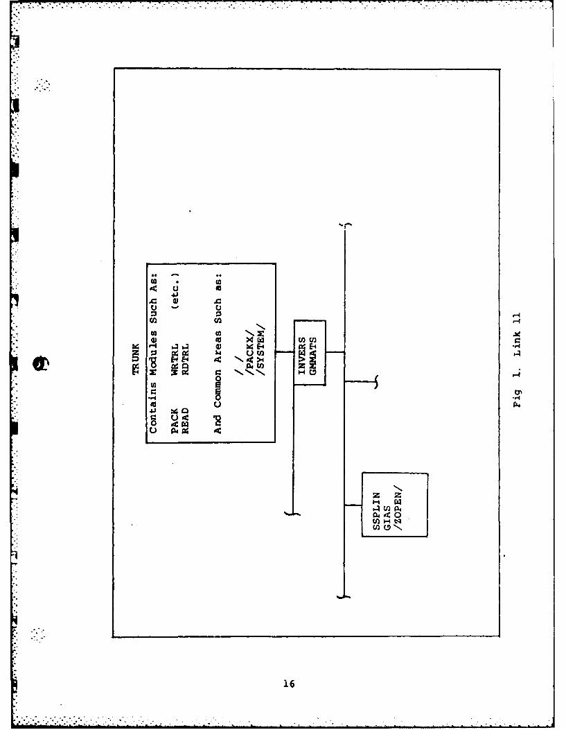
8. Put the module inside NASTRAN. Because SSPLIN is
one of the utility subroutines used, GIAS was put
into Link 11 of NASTRAN (Fig 2). The other sub-
routines needed are also available from this
position.
9. Run additional test cases until satisfied. Both
the simplified wing box mentioned in Step 7 and an
intermediate complexity wing were run as final
test cases.
.1
g 4
!1
. --

IV. Loqical Procedures Within GIAS
It was previously mentioned that GIAS created various
transformation matrices and moment arms. This section will
look at each of these datablocks and outline the logical
procedures used to make them. Several of the procedures
overlap within GIAS because several of the output
datablocks use the same input.
Output Datablocks
The output datablocks are:
SAS - A matrix containing ones where areas are
0in the SKJ matrix
GTAK - Surface spline interpolation matrix for
transformation of 4P's at the aero
points to 6P's at the structural nodes
TTTTT - Transformation matrix from AP's at the
structural points to loads at the
structural nodes
VGLS - A vector with ones in the proper positions
so that when multiplied by the structural
loads it sums them. VGLS also condenses
PG down to nonzero terms.
VTMA - Contains the moment arms for the aero-
dynamic pitching moment about the Y-axis.
18
--- --------

VTRA - Contains the moment arms for the aero-
dynamic rolling moment about the X-axis
VTM - Contains the moment arms for the pitching
moment about the Y-axis due to the trans-
formed structural loads.
VTR - Contains the moment arms for the rolling
moment about the X-axis due to the trans-
formed structural loads.
AIDMT - Unit vector of lengtn equal to the number
of aerodynamic boxes.
Logical Procedures
The first datablocks built in GIAS are TTTTT and VGLS.
Even though they are built at the same time the logic to
build each of them wil be considered separately. TTTTT
transforms the 6,P applied to the centroid of each area
element on the upper surface of the wing model to loads on
the upper surface structural nodes. The first step to do
this is to multiply the 6p applied to the element by the
area of the element. Using the geometry of the element the
load over the element is then correctly partitioned out to
each node of the element. The only information needed to
calculate TTTTT is the coordinates of the structural nodes
on the upper surface and which elements they are associated
with. Since VGLS is a list of ones in the Z DOF position
for each node on the upper surface the only information
needed is the upper surface node numbers.
19
The next datablocks built are VTM and VTR. The moment
arms for the structural rolling and pitching moments are
simply the coordinates of each upper surface node. This
information was obtained when TTTTT and VGLS were built.
VTMA and VTRA are built next. The only information
needed for these two is the coordinates of the corners of
the aero boxes. From these the coordinates of the 1/2-span
S. 1/4-chord point of each aero box is found. This is the
point of each box where the lift is assumed to act. The X
and Y values of each of these are the entries in VTMA and
VTRA, respectively.
All the information needed to calculate GTAK is now
available. In order to calculate GTAK the subroutine
SSPLIN needs to know the coordinates of the input and
output points and how many of each there are. The input
points are the points on the aero boxes where the pressure
is assumed to act. The output points are the upper surface
structural nodes. Because GTAK has to be built all at
once, rather than a column at a time like other matrices,
this is the procedure in GIAS that takes up the most
computer memory. In fact, depending on the problem, this
procedure could be the one that governs the amount of
computer memory required for the entire analysis.
The last two datablocks built by GIAS are AIDMT and
SAS. To build AIDMT only the number of aero boxes is
20,--..,.

needed. SAS has ones down two of its diagonals and zeroes
elsewhere. It has as many rows as two times the number of
aero boxes and as many columns as the number of aero boxes.
21

.V. Running the Flexible Wing Solution Sequence
In order to best use a solution sequence it is
advisable to first understand how it works. Therefore,
this section first presents a detailed outline of how the
solution sequence for flexible wings operates. Afterward,
an explanation of the Bulk Data Deck is presented. An
example of the input deck is given in Appendix B.
Logical Procedures
The first part of the solution sequence (from now on,
called DMAP) sets up the tables that de.scribe the
0. structural model. These include ECT (Element Connection
Table) and GPL (Grid Point List). This set of matrices
describes the unconstrained structural model. The
constraints of the first subcase allow only rigid body
pitch about the wing root trailing edge. This will be
found in the eigenvalue analysis and used to set the
initial angle of attack. The frequency limits of 0.0 to
1.0 on the EIGR card ensure that this is the only
eigenvector used. The DOF are then further partitioned
down by Guyan Reduction to only the remaining Z DOF since
the aero model can only tolerate displacements in the
Z-direction. A real eigenvalue analysis is then performed
within a small frequency range around zero. The purpose of
" "the analysis is to obtain the mode shape of the rigid body
22

pitch mode. The Z-displacement of the most in-board
leading edge node, not including the wing root, is then
normalized to one by selection of "point" on the EIGR card.
All displacements are multiplied by a user calculated
parameter, AOAP, in order to set the initial angle of
attack (Fig 1). This procedure determines the zero-camber
initial displacements of all the nodes. The indirect
method of determining this is unavoidable because COSMIC
A STRAN has no module, or simple sequence of modules, that
will do this. Camber is added to the wing, if desired, by
using a parameter ICAMB and a matrix CAMBER. After this,
various transformation matrices are built. The first one
created is GTKA, which is built using the Bulk Data SPLINE
cards. This will be used to transform the displacements of
the structural model to values of slope on the aero model.
These values will then be used by the aero analysis portion
to specify the strengths of the downwash vector, DIJK or
D2JK. This vector is then multiplied by the aero influence
matrix for the Doublet-Lattice aero method, AJJL'e to
determine the rC distribution on the aero model.
Following the calculation of GTKA the module GIAS is called
to determine other transformation matrices and moment arms.
This ends the first subcase of the DMAP.
The second subcase is distinguished from the first by
a change of SPC cards. The structura' ,r.Ael is
reconstrained to allow no rigid body motion. None of the
nodes on the wing root have any active DOF; all the other
23
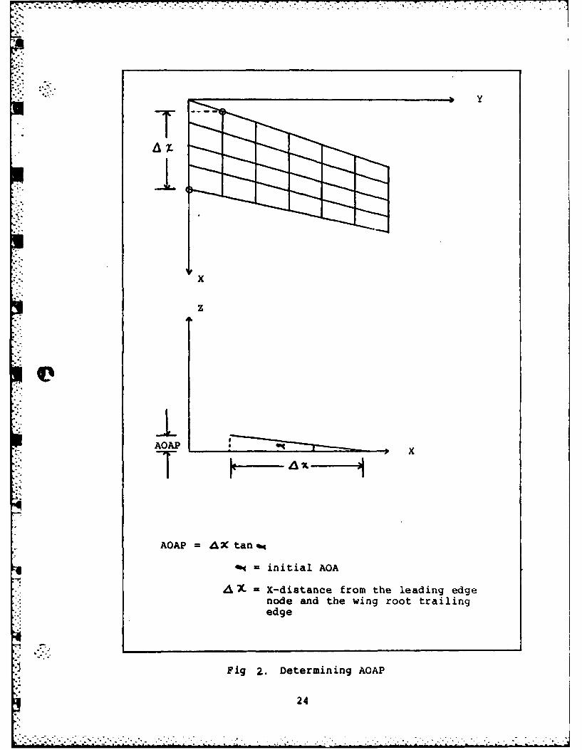
x
z
AO"P e
AQAP A 2C tan
ft initial AGA
-X-distance from the leading edgenode and the wing root trailingedge
Fig 2.. Determining AOAP
24

7z7-
nodes are limited o only translational DO?. These nodes
are then further reduced to only the Z DOF by ASET cards.
This procedure locks the wing root at the initial AOA as
determined by the eigenvalue analysis and AOAP. Then the
matrices necessary for static deflection analysis are
determined for this configuration. This analysis is then
performed to determine the structural loads due to the
initial AOA.
The next section is the most significant one of the
'DMAP. The iterative loop calculates the displacements,
structural loads, and aero forces due to the structural
deformations. Then the structural deformation due to the
new airloads are calculated. The loop begins by finding
the change in structural deformations due to the airload
vector. On the first iteration the load vector is due to
the initial AOA. On subsequent iterations it is due to the
change in structural deformations. Then the incremental
deformations are transformed to slopes on the aero model
using the GTAK generated from the Bulk Data SPLINE cards.
These slopes are used to determine incrementall(s.. The
incremental 6e, are transformed to an incremental load
vector which is used in the next iterative pass through the
loop. This is accomplished by premultiplying the aCe
vector by GTAK and then by TTTTT. At the end of each
increment the changes in deformations, structural loads,
and aero forces are accumulated. The loop is finally left
when the norm of incremental displacements (VNSR) is less
25

than the user supplied parameter ELOO,?, or a total of ten
incremental passes have been made. The loop gives the
final values for the structural deformations, structural
forces, and 40, vector.
The DMAP then recovers the complete solution for both
the analysis set and the omitted DOF. A complete stress
.- recovery for all the structural elements can be done if
requested by the user. The final section of the DMAP
determines C., CP, C,, due to both the final aero forces
and the final structural loads. Both sets are calculated
to provide a means of checking the accuracy of the force
transformations between the aero and structural models.
Implementation
0In addition to the usual model used in structural
analysis there are a few more cards, and one additional
datablock, needed to run the DMAP. The extra datablock is
TOSEL and is entered via DTI cards. TOSEL is the table of
area element numbers on the upper wing surface. The
records in TOSEL are organized according to element BCD
names. A more detailed explanation of TOSEL is presented
in Section III of this volume. The additional cards needed
are (Ref 1):
ASETI - Defines the DOF in the analysis set. For
the DMAP the analysis set should consist of
only the Z-DOF for every non-wing-root node.
CAERO1 - Divides the aero panels into equal boxes for
the Doublet-Lattice aero theory. The param-
26

eters on this card are determined by the
wing planform and the user's needs.
AEFACT - Divides the aero panels into unequal boxes,
used in conjunction with the CAERO1 card.
PAER01 - Defines associated bodies for the CAER01
card.
EIGR - Lists parameters for the real eigenvalue
analysis. The frequency range of interest
should be from 0.0 to . in order to
include only the rigid body pitch mode.
There is only one estimated and desired
root in the frequency range. The eigen-
vector should be point normalized on the
Z-displacement of the most in-board leading
edge node, not including the wing root.
AERO - Defines the basic aero parameters. The DMAP
uses the parameter Q, the dynamic pressure,
and the mach number frr, m the MKAERO card
instead of the parameters on the AERO card.
Therefore the values on the aero card do not
matter, but they have to be positive to
allow the DMAP to complete the processing of
the AERO card.
MKAERO - Defines the mach number and reduced
frequency for the desired flight condition.
In the DMAP only one mach number and
- reduced frequency are allowed. The mach
27
. . . . . . . . . . . . . . .

number should be subsonic and representative
S-of the desired flight condition. The
reduced frequency should be a positive
number very close to zero.
SPLINEl - Defines the parameters for generation of a
surface spline to interpolate the out-of-
plane displacements on the structural model
to out-of-plane displacements and slopes on
the aero model. The SPLINEI card is used in
exactly the same way as it is in the flutter
analysis rigid format.
SET1 - List of structural grid points to be used
with the SPLINEl card. Normally the list is
only the nodes on the upper surface.
PARAM cards
AOAP - Used to set initial AOA. Real
number. It multiplies the rigid
body pitch mode eigenvector after
the point normalization is done as
specified on the EIGR card.
ELOOP - Tolerance of convergence for the
iterative loop. It is compared to
the norm of the change of deforma-
tions for each iteration. Real
number.
LMODES - Number of modes to be used in the
modal flutter formulation. Since
28

the only desired mode is the rigid
body pitch mode LMODES is one.
LMODES is normally used when
several eigenvectors are consid-
ered in a flutter analysis. In
these cases the different eigen-
vectors are arranged as columns in
a forcing vector for determina-
tion of modal pressures.
LMODES would then be the number
of columns. 'MOVE is a real
number.
Q - Dynamic pressure. Must correspond
to the desired flight condition.
VReal number.
RC -Root chord length. Used in formu-
lating aerodynamic coefficients.
Real number.
WAREA -Planform area of the model. Used
in calculating aerodynamic coeffi-
cients. Real number.
As an .option, camber can be added to the wing. If camber
is required then an additional PARAM card should set
ICAMB = 1. Also, the CAMBER vector must be input via DMI
cards. CAMBER is as long as the number of corners on the
aero boxes. If two or more aero panels are used then the
- common nodes on both panels are counted twice. The values
29.-.

that are in CAMBER are the Z displacement of each aero box
corner due to the camber of the airfoil. In addition, any
control surface deflection can be treated as if it were a
change in camber.
Finally, in order to run this DMAP for aeroelastic
analysis of flexible wings, the case control and executive
card decks must be formulated. The executive card deck
must reflect the fact that a DMAP is being run rather than
a rigid format. The case control deck notes the set
identification number of the EIGR card in the Bulk Data
Deck. The case control lists the two subcases and the SPC
identification numbers for each. In addition, output
requests as needed are specified in the case control. The
values of the first subcase correspond to the initial pitch
configuration; those of the second subcase are a final
result of the iteration loop. All the available output
requests for the static loads analysis rigid format art:
also available for the DMAP.
30
-..

Bibliography
1. NASA SP-222(04). The NASTRAN User's Manual (Level17.0. National Aeronautics and Space Administration,December 1979.
2. NASA SP-223(04). The NASTRAN Procrammer's Manual(Level 17.-O). National Aeronautics and SpaceAdministration, December 1979.
3. Hurwitz, M~yles H. Course Notes of NASTRAN SystemPrograming. MSN Software Services, 1978.
4. Schaeffer, Harry G. Course Notes of Direct MatrixAbstraction Programming (DMAP) in MSC/NASTRAN.Schaeffer Analysis, Inc., 1981.
Lw
31

Vita- --
Kim Jones was born on 28 February 1958 in Weisbaden,
Germany. He graduated from high school in Clearwater,
Florida in 1976 and was subsequently accepted into the Air
Force Academy. A year after receiving a Bachelor of
Science Degree in Aeronautical Engineering, he entered the
'School of Engineering, Air Force Institute of Technology,
in June 1981.
Permanent Address: 837 Island Way
Clearwater, Florida 33515
32
..... ..-

Appendix A
33

v N
o oC' Oee o o eo'a
P. 6n- A.- 6 . h
- a- I- C-I-i--,-.4... K in
all
.6 x
I.-
A bg m6 o% 44 mozc 64 Iolacc,
14hw c0
6. a
K ac& Noa WbU6 . ) .I
7- 7. 71 - ..
C aC4c
14bi 1
c C#4:
7'
4c c
ir 1.-
19 4 i
4c
4c6
1-4 4m-
z a- 35

-- 9
UU
anC
.4 Z .4
W, IC-.
u S. z - -- I..3 I - .4 46 soa j a t t a 0 1-U x1.- ZA 03 P. I Iti zC. a uc '
-C 49 a to 016 - w 6 = S'IU A 16 1 Z. 406 .1 CJ 't06
1..~~I hi "I ..'hi CLU h .C *9h 0 - C a2 It . 1 ..
al- w - 04 In 43 A I- 'C 6. o 1 UC - I c=lit w I.- w -him C IIIUanxV K v
j N. u 0 t; r- c UC 0on Z 44 w 0P- -? . 4 C, h.2 wo 21 w K
Q Km... hi I i h .:
a.S .42 0. w a. 6. a w v - 'AK* M4G & =* 06:44. Cz~ ; 1 N- U sc V
IL C- Q Q M 86i K K
.J*.4L . c- 0- 1 . M C I. + S Kc K*2 R:C co I" 2 . : . U
ww....2LI.. 4 43.0 't. Oi r -1 4- z~ .2O I.
*2UU. .. 32 IN 2 40 .23 1.. S.CIL
Usa-wIW U U 1. u24 *U2 w ui. vk w 3U0 u 40 K U L 9)vU LL; -I-UK K- w .. U C -N v vu -Cv w.. *LKIUUv.U U
*2Su uu w w .1. .3 S.CS.2- ui C vi L UJ UK IIVLUL wUv L
- .2.. 4 h h 0 2 .h IM K . s. IS...UC0
S i~-.m .h K . hI~-C 0 C -C I- - .. O~. OO 36~P

w
1iU'
0i 0
0. 6.k LrK~ w.
.3 Ai 'Ax
hi l 99 W 0 7-
3 ~ ~ ~ ~ I N a 3 CW- 14 80. OR IC I. z .4 i
16 4c .3 wh 1. 10 ol I- w. 14~G c A. 02 4-1 N4 0
C 0 3 1 Qb 04 hi IL 4ow g- hi M. 69 IL0 .
* ~ ' 1& 0- M 4 M.. jhiU .e a4 -C 3 00 - 5 $--1
-. 1. hi ha hi . I.. ,rC .- CC 6+ .Q1U0 + M 60 a34 0- i Z
hihiC West 0-1 3 ots 0 a - .4 1
NC bA z 1-4 .1 .4 0 0 hCc . 4 3 1*4 VI Wh 10hi 0 0 4 hi:.aZ 1 . 14 C" .u
S .4 1. 04 4 mg cam 4w P. vii h 3 4 4 4 ~W w - 1.O 1.1.i 1. -4 a.h I. 3- a. a- a. a,
44 U hi U1.OhUiW VW hih WU .4 01 1 W USI L V u.5 .4u4..0 1. h 3 h.OWw CW hi 43 hi 41 h v 4.4 c1 -
- 4. 1 0 ~ h03 W - 3 4 44 4 3?3

C;
C -
C Z)
U0 u u iC~.a i h hi to 'A -CW t , -CO -2: t. I- a
£ ~ 1 hi hi 0 U ha 14.1 i .= 3 1
99 1.4 .h6 w w4 -P. C, 0 hi 0 i hi0 'A WWU;i-A
a M a 1 0 m 1- 1.1 - 4 a69d 4j 41. WS S-iKC ngo 61 .3 . =a 1. 1. 0 C A534-
I. In 5431 1.. m h. tU I.. "P4 W % a 00. la h w va (44 -C2W.
C1 K i4 - a a, Cc 3. "ft tz 9 wI aa .
I.- A w fC Ow a 0 0. ainUU~ h
- 0 l 40 3CC hi a" 3.1 W S 0. 30 i-h NK V-- X W
6- UK -so 0% 1 14 i-h A MJ-*0 C~i 0 0 4 0- 013 a4 CC U6 C 41 4
hiN .9 -C 1-30 9bc a m 05 u -hi Ni o. . 1"o.1424 t5-r hi . C 3U 144U .3 - 14114
hi 00 1 0 Ma0wh
ML hi ,a a :40-00 lo.4 1401 P3h.
&hh~hhh 4*@ 1. CM au w0b NaM &IC 6
ui-~u- h .u-~iwI-44iM EU a4S Cmei 1"S O1 hi IC IU *-5 L I3 2
hiC0K U-i..IhC*i* UD W 164- f I-- L? Z I~ -W u.i I.-v I
33 4 0 Kz MO-.. 43.24K--- - -i~a~- : 4 1 i-uK 4
- biI-t4I
uuuu u w;Juw u uw u uu w uu w UU vw uUt u Wwuuu U~u0 uvu uu us, uu u u u u) uU W U u u~ v u 1 UUL)UuU
wuu wuu uu uu w, Uu u uu uu u uuuuu vutiUu..:
2.2.
- V1
4 c I& .
.9 IC w ita b a k*
c U i 0 i U0 " - 1- u3 96K
.Ln z b. .3 c
i, a . 3) -C r - W.
.4 r. -C a C4I' K 4- x3 Q U
a 0w- . - W " 2 c z!N U-r.. I- w .4 0 0 T.- a- it
w is 'i . . u -
le 1-A 11 'A C1 2l 0- 3 -.- @-- A- w- I.. !C a S.W
at = " < I I . me h ws -C -C K KaeIi C c- 'AC U. La P.a s r . c I-- a w I g a
s o + C -0 fl4 u 1. 211 '1 I *6 t
mc~~ 1 0 : CX .4 S L W .3 AI-m -C 8- a. EZ 3- Co Cw i c
0. .4 4 w- 2 hi .5 M .3 ILi-0u C are w i CZ S IU I mC U 0-V. c. , 0', diW. W4,4 .4 .4 .4 .3 + W. 16W.- - T . C K wu C'I- ZS 13.- la I Gn CuD C - I
4-. Se C-IaIZ _I=W - V. C - in =1 PC w .CU I-c uC C &i- a
C -C z 0 Lw 2K .4 W- It8. j. 69 -CCC C IL 4n wih U
Ut h inhiL0 0 0.- 9 C- aC.
U3 UU -l-UU U3 I-U w Ui wU w .:~ t, w t- - C L
in-mCPdUH4 stmN.... CC C~ZC839.

---- --- -- - -.. r. -- - -
C-C.a
u . 6. I
5. SC 0 !!hT
IL2 a- -4 :rh Z 1:c .- 161 1 A- 161 0.
lu .J a- w U
c~~~ -e.ua-
1- i a- w o. .0 a- 40 - r
6 * 3 1 2 1 . 0c cSiI 3h
4I-C I0.ZM 2
.. a- ua ba W . u L C, - 0 a.hi a h1 a-i hi Ihi*U k i-4 +4+4 a.+
Chi~~I 014 Si 9-I..i V.s > > i m a C C a
IA Nu S ~i Ks44 hiU C5.. -, - aU.c
uu a- a-IAUU UU v... - W2h LP Li2 vIhi vi wi41 L Qii~ WW .525.-a- U .0 vp5 412~ CLi C*41
o~~ ~ ~ ~~~~L +-S + +13 i44 ~ MaS~~4UU.4
-c 4 S il *~ C425 * S. 3. h~hhi a-0I

. . . .' . ::~
a.. I'-.,* * w .t . . h*. .4 o. c
4 z .00
- cm
Po )* C a m w 4 6w
I" I .. C1.443 c ~ uL
Oc in oo al UU 46 -3
C = C I-c Z9 C C 5a
wzz w u wl mm z acK =-E4t: n
14 * C h SC i* -uu Wa Uu u VL
o- wr"'
41tai

-3 C
o~ r,
C.
0 c 03-1 3c6 CI ,I: w W C I... u . w c
a. w~I in n @a
t Ca u '1 I- CEW19 .
P- U O - -C W
1-l -9 0. Li
c- a. h .cLzM V. 1-- U j
I- ~ ~ ~ ~ -W.T w . i
a. W-C U. U E C C,hi 4a .I. b-tt.g...at:. ,:
cIbQIN-W xx4CU. z
L; bu 1-.i-a. U w Ld Q - C
Cv. u C3WV Ui 44u w.J 4U v L*. wC v
'C 4 Ua-4U I U42
ii
%','4
CPCc
6- " if.
+ +
.4 3 w Iw~ 96 1C K c6.-
v 16 IL 161 A ,.mmm
+ +h
- *p~ ",, C>
-0- .- 1
,- 16 9- + +-
-, - - <x It ..- I. . .- I c r_
W 4 - -P w
hi1 06- -*
'44. a a u.
%,,
C. w.--. u. vi u .L V hi)V
V 6111 00
43=15.2
C-a
C4
hi bg K
A &. bd bc I iS.1Cb
* -C a hi +.I
61 a In H. U0~~ ~ CiA n h
4I Z hJ C 5S U K S - a
'16 60 bt + 0 w ze C w uK~b ai w 3 *
V. 16 4 jin iniz C K I
H I Uoa K z Si 'C- aC -C6560H0 C K 61 mi c o- w I a z.
UNS CU2 1 I 1a I I I C 1 1O * Z I o* C, auC K K; A -. b-. .4L A- r M a in L 4 5 <ci.-.I
*g 5i 0 W I Z C L, hi -'L a9 W CIAC C H4
C K v u a a a u u in
£0 0 K U K 4P
CH - hi hi i~hU 44C

• ..' ."'..-..- .. '.-.-.-.-,-...-. .- -. . . ..... . "- -- -. . .I _ ..... . . -..- . .- k .. . . .i
.
.
c
C
UQ4c
p.0
CC
CC
0.. ...4 1-
oo
IC L -, zr r
I- Ce aM4n Q
iz --C
, ,C I-Z I,
z. w W-. 0
., ... C z W N3 -
a- c le 0. 0Z-D .0 w o.Zf
as - - -C0
33. PC Ce M
OZ.. C "1 1. "t 1.. It I, 1., 0. g ... 1. 1 c "1-,- N UK3 I-I~ X M rMrI 6Z U Q Z0K <M X2 - 0. U
Lo. U v 0. C
L.' U U U U U L
0 c h
V-. N .4 4 ~ C *4.1- 2 0.4

w
10 -C
-°C.
OL hi
0 z
:: .. 4....
A. --
'C.a
cc c
I. C... .414hi14.14. h .
a. . C . 14... -4-l---
C + ........ - ,, .. ... :..
- -C
"-o,
w--
I..z
£ 46

- • ... . .
1
z KU. 163 6o 1K6a w K1
,r. -6 :
0- :I& W 41
- 4 "
I- Z, Z. P 1
"1 K K
46... t 1
&g I4 j 4 Z X4 CI.N j r
--€
0 0. I.D 0 Z l -
K44-..4-...,- ,.4N.49qe e-
0c 'a c & w 0 U
-47
[ ,,
4K

-c 0
c~b eQbcc4
633
'A ina ia c x a
C. inin h
4' 4
fn 4' .6 's #
10 of ,cC: 3a
4's-1~~~u T5rn 05i -5I
tIto co S.) -- -
- ~ I Km-mmU a w :-~f~ I-.n .4~ 44.4qp..E u.
ff.tV P0P
S... a ~48
5. AM

4.s
.00
CC
C-
.3 -CI I. #. - ' cC
00 46 0-
4.~ at.
0, - In.3 A I.- u
X9 r. -. r .3 -n4 a4 a4 x ac
m- .3 w r . & zp .9 WI- -4 ; cIa. w w 4_ 0 1.wt wA.w
u w L U L: w L;o Nl o
4- a- .3Q
.4 .4 * 49

* .r ~ -.-.
. . . . . . . . . . . .. . . . . . . . . . . . .
WI
ICI
w a
- v 4, a UU u
CZ lpI 0 a, a
a50

-.-.- I* . - C.. -a-~ -
4c4o
bi4
.3 4 2
Q - -C-
00 .. .
-0 ~ ~ ~ b b4 .0b .c xI -ClI -1 O3 16 '1 a C W* 0* K
C 10 lo- W4 4, K
u u 4.* 40444 4 -
V%* -I- dp u u t- a,
*Q 4. - .* *4Kc
-% .4 - . 3 *El -4 - N K51-
-- . a -i w. C -C -CG-
PI-
C~I hi .. C4 4
- - 4 j C.I
at C C. V\ a '0 A4N
90 NN4NZCI
£4 44 -, -CC . .
C 44 44
1- KK KK Z .- C4 - 9-K- C lIPew 0 cwwht wwwwwohih
r- C,
4. h.40L4
I -C -ID C C. 4C i
-. C C.-
CA
4 r S - tN N.KC52
0
ar Z a a Ezxt
- * C hih~i hac0 nI 1 n0 n0i nI
06k C1 .1 b . Zt 1 b!.6 t iI
tC:l kI ,nga. n 14
- -Cpienrc. 'A
eta~ cat
I0tW ' eSltc--C0rCFlNvSW
t~t *CN
4~~ 4 a: a t a a
e4. .0 a Z-ft4 04 0 ~ tf C.w wC I 0c 0C 0
-~FaInn ifu~ iii hn fhi4~U E. ni
h~h~~hb bababhhbhh~h-ah~53.hh

i in
w. L
.
,
6.1 1. j
C.4
x w : al v c-
II
C I. - I . 4
C+ r u tt 4 c I w -c w
..
. - .
.z S1 . l- I
-C
rr tr
-C
4. '
9,c
4,.CCAI.4.2j. L 0 4
6,'cI I
Cz
U+S+
S+ W
* C-
ISS
j a.W e 9hi. C" 0. t 4 r
t I- o : - 0 a
C C A
*~j Tw u S L; 5. L; W v4 .Q
K I.i 4 rhi Z 44 hS.~ -f4

r u b z r . . .... - ... . . . . - * *** ..w
*~ ~~ ~ ~ ~~~ + , - - - - r r - w r . * ~ l r f
C C
Cor
a 3-
c +'
r a-
4 456

CC
- I .:
" C; -
00 C *L
4 z
Q5 4
5:
t- ...
[,' -. , . , ' ' , . ° ." H ,, ,".,

D-R124 6 NSTAN PEAT I OC N S OF ECHL WNSVI/~D-A14 62 STA ARTEL A IOC E NAL S OF TECLEHNGVI22
I NRIGHT-PATTERSON AFB OH SCHOOL OF ENGINEERING K JONESUNCRSIFEDDEC 82 AFIT/GAE/AA/82D-ig-PT-i F/G 1/3 N
I flfflfllofl.....I EhhFENl

*~ .. ' ,
i l . 0 MCOOYRSLUTON M2.5CAR
*A w
2 - . I ".3M"
1.5 L
MICROCOPY RESOLUTION TEST CHART
. '-_ NA TIONAL BUREAU OF STANDARDS -1963A
- . ... : p.

* ~ ~~ ~ . ..--T.~-- . ~ . . % . .. . . . .
c C4
w .a 9C
4 2
og o
C U!
I-
Ck 3
4-- I-w .c
t73 3 3. 3 ~ :4 ~ 4 4C : a.
. 4 4 4 ~ 4 ~ 4 4 ~ . .
IL a3c N C
4 -58
96
44
a.t
4.4
-~ 0 0-mr low 6",-4.
IL -Cn 0. w
4 -
Uw46 W N 1j ..
- z 44 10-- a~~h a ga t a 9
u 1w w -C -
U0bahihl0ihi - CC4
Ic -U
4459
I, * ~ *~ .. * *** I M - I. ..)
w4 21 '
I.6
IS OC 0 C-
89Gf I
10 #A 0hC C
-C =5 4V f 0w ;
11~~I -. ICC
. I- - C
at 3 IC -C w
*6- t7 1f
a~~- a- aV-3 1 .
1--
*~~~U u w L;SUU C31
S S h SS60
u tw090w -
+ +z16U0
ws.W
- w U4b"
Ci
p. -.
Cj
OD , f
A6

h6
44
C
I- S. z. S i
*I00
* rla
IM I
£z 4
4 ~ ~ ~ ~ .Uhhhhhiiinihhhh4:~~~~ ~ ~ hi hi bi vih ih ihih ih i
N re" c 1 161- ~ ~ ~ P a iihhhiiihhhiiihh
IQ 33 333 in3 3 3
- hih62
-'a6
Kd
24
0W
00
0ft6
40 19
49
W . 14 a a A
1 4 4) 0 , .Cn'a log ha 3 0
0. Sao lh 4 me 2 02* 44 a. - - ao C
a ad 3 4 4, C;m
W 4 0 b3 14 U o 4 .201
a towI.AI .~ . . I 3
0 age 30 ua a~ -
004 1. .4 4U 4". 06. -K I.
U- -C Mo. log W. a 0 2
0~~~C 34 @3 0~i t
ad Igo 0 i -- x -. :. 0 . a 222 C* 3-4 3-6-4033 U 4g0 . 62
UMO S4 n 3-34. 0-U U C2on fA 3. I.4 40 g 0 Qa 6
*~1 04 Aa.0- 0 3* 3.. -4 -c. 361 o bi 0 C2 3G 0 0
OR -cmaa -...3. - 0 o DM a C a4
- -. - a V.@34 *0 i4 44 2 4. - Ch 0
34 M 26- ilU -3E4 -04 - 4.3 3 .m-. -~ 66h 6 4 i 2 C .
u -u w 3 3 M E h hb U 4 ...- - - .6- uw U 4 43hi@0U wu uw U L 43 u u wa 623
a. U 2.Ub I M340 I h * CC 6 ~63'

.. . . . . . . .
4
'0a
02
j A
.. ;
V- - -
c 0 0 0 -. U aiA o 0 '1 @a .41b C w oa
X's & B. a a
ow 0 u 0 m R 0 .0V
B. cc cc0 0
0u 20h 0 qu - u hwa
LIS - r0-0K.aC * B. .J&. 00 0 Wi 0 ' -3 0-
'* K ~ .-. . ~ ~ 0 - .64

-c. 1-1-1- .I." P
'4&
a a
-. 1'0 i u
Coco
0,:
16
-~~~ W. &I0 00 0,,
10,0
hihhhaahw haa-. w.a
I g 6. 1. t.. 0.P,4 - -a all* 1N11 Q
a h
PC 0, - -
ag.8 n OW. : A'4 -0 0,l .4 Ii 8- 8- 18
X 1A saw M Is I.Cc o^0 c0 Cccc cc CQ
0,~~~ 0,,,,,
0
0000000
0 33D 33 3 33
* m v0 0 a -4 @
8- 8-. *. 35

opi
IN
P.
a
LA 3w w
b4c'a .
w c
* U1
h66

hig
la 7
.6 .4 ;
.4 c
m 6 'AD-o4 c v
2' 1 3C
164Xi
hi 66 t
a6

-IN
.. 1*0V.1
44
.0
aa
-9 W.0 ona a -
86 UbI
A. vi w b 1 m % 1 43
C-
-C c
49 0- P.
kia a-i 6. b -
U ~U h68

LC . aa
A~C4 .9 a.*. ig ac z.. . a a
w a 5 I
haj
CC
C1
-. K
U :a C
z 0 +
96 9
4C t4
C0 0
a r I
u u u u u-C 4 C46rw 2 www
i(0 (0c5.3Z.6
5.~~ it .6 6
UQ -0= Q.5.Q
2 3 60

.4 bJ
i '°

FcII
C-
444.
C- I-.- V .CCC
04 0 c c c
-C '
r. 4c 0.a41 4 -C #- wa
at -C4-C -
-C -
f. .L WU Col co C&- U 63 a. .99
13 xI- I'c
0 -o C
- '71

-22L
4n
. i
z
I-
&C .
f.
$- I-soj
41 6
.- 172

636
9L.
I-C C
06V
4 6
ig -M w t
I-- no
73

6P
aI-
.1i
4 81
• -P...Jp
U xSN ,4 mU* C N
.. .3 u 0 0 -
C. 2 t I-
IQ a. 4 9AI 0
' ." ."
. .li P )wue 0
ft
.'. -. , • .- 8..•._ 7 4
- ' -.' . - -. ,/ : ', .i . ~ ~ , ', ..,. -,• .- i •N: 7 N...., .* 0 C " . 38 i . •2 , ..•:..

ft
hiU4a.
.4
.4
C
Cft
4
C
.4
.4
44
aI-
0C
0 4.4 C
o *~3I-
I-- C CCI U I--..U- -~ 0--, .4~ Ut
2 4.3 1 4+- .4 2 * 2 ~3 ~* ~ U 4 4I- I.' U- ~ 14 D4 hi 1. .4. I- U... 6o m -4 I~ -U hi hi
-. 4 3.3 2 U 4 42 m4 .3 2...&. U _ 4. 2.-...Z . .1 21 _
- U 2*'..+ - - 2...4~2 -4 hi U *44..4 * U .444 * hi~ .3 .... 36.J hi .~b4a. hi .... Ju~* hi
* *L44. 2 U 01.1 34t 4% ~ *~4.3 Z 4.4 4 4 .. 02U *ft 444 .4 .4 0 ... hi..Z..~ 44 U ~N 04 .4 U N.~ 0... - U ~'NI4 Ua. a.
USIE 4 C~*U 432 34 4 C~II 432 32 4 CS'1 4...4 .341444 442~4 .J4444 4%44 .344.~44 4420 ~ .4
C ftM..324.J~ I .1~ C ft4244..3 S 4.~ C .N.....324-J~ I *J~.... U03- 4 ~1.2-4 4.3.. 4 '-U2~Ui.....Ui 44.414143 4* 0 UUI4.UhiUUhi 4 0 24u~w~mwui 41 0 hiI4enhigsnhiZ 3..~i4 U C #.jU~ 4 C ~J..3... U C NZ.~4ZU4
C4'.3 UuU 0 0 UUU C C UUU 0 CU UUUC 4 '4 4JUUC 4% 4 UUUC '4 a.
UUU4 ft 4% UUU4% ft 4% UUU'.4 - -43 42
I-
C* 4a r
ene C 4% C C 4' C.4 .4 ft ft 4 4 a. C C
75
S. . .

-... ,
4e
S.m
•4
-9-
- ~ f S. bOO 0 0 4 4
6w id w w MaO,* I " i.
k;' m b-3 E
.... e-t .o0 86 16- & I.t.I .
.',a at 0 0 0 9,
0'9 89 09I
-... -- e
4CC4w
,,, ibi 4bIm iihhi bi hat at at g u
•9 s - l " a.1 .
=. I t 0 ac,. a ~ A Ir
AP .4 M ,
la Wa"ou.
'1 .6 -L; u-. c e C C 'A
W W Is a $-~~.00404P.& : a. 4-1 _
IAcKa-wf tm41 - - N N
U- ft 04f 44 r I-wo U V45. ftNf 0 4 %
hi in
4 3 -76

coo4 4 4 4 ~ 4 ~ h 0U cc .
coo c -- -00~~~ a 2CC!a 0 - a.: co M
C)ih a i C, ih - .
0000 am,~ i.
a .c 0 C4c
'm 000 000 C c IN4 C* 44 44 4 4 0
0 *0 0, CC V~hC call 0 00
O COW. OO.Wc
c 0 0 COi.5 V. - 4 - 4 - -
O .E44 0 flhc 4V. c c
ai I. Ii "f::4 - C~'h
..hh 1-iih h -,1." - -
--- -- - C-- - -
COOz CC O 0 0 ++ + . + +. . . .
COO Cv.9CI-= 3 -

++ . . .. .. . . .. ... ...
cc nflflflflflnnna., ar ccrap,.. *
oCoocooogooceo cc Coco cceeocoaoeooooac0cccc0o C ococc co CrfO0ON 0 COc co000 000000 Coc co oaocsAOcoOCOCCOCCOOCOcoccC
o eoeoooceoeoe 004 oC C-d0en.-ee.Co ocz~ecoooo o coe0C 0cco-ee -0O n 0-oe0 b~ ec
cc cc e 0 ~ n -- c- a v .
e oooeoooeeooooo --- - -- - -
cco C 0 C CO
o C ,D 0 C^ f
0 oNc o o OO C O e O C e O O ecoocecc c oc e 0C cc
cecc0eco Ceoooo I ocCcoeococ !ceococa0 .~4e0e eeeo cn eoceCo-oICCo~c c S ,c C
C S00 0f 00000 *~ 00 00CC CC CCCQ 0 C 0c c CO c-
eeoeeceCeco ccoccccccc c occ
so osocecocce C~vC c c~cC~c~~ oc
bae 00 oeeoeo cco o o cco o o o c
4OO 000000 WOAN man~v c N~cf
454VN~~N CCC C N N 44N N44 C~C447

Appendix B
79

* -i W -C
b) 3.1 0.U2
go P . 22
ad M M m -C w
hi~~i ht in3 c*33
r 40 tt w1 4C0 u.. Ic 6.3
.2 U,6t w 0 hi2
gm e.. hi- U33 a* I6 0. .3. ..Mot
0 ;; 0 * I;_ Z ac 4 -uw. .16 **.6 U 04 a -- U . 41
0e .2 3_ kt - 1- La I-'V.hi ~ f MW 3.3. . s"mU * 3.- C. * h * .
-~~I 1 Zii 2 6 3L W .6 .2 U - * V.i ..16 .. hiU. -- 0- .3. 2 . 4 0.6.3
3.- 32 & U06 U Z0 -d z t0.hi C -. 2 ~ 6* U -L) 0 .
a a. ~ ~ ~ 1 03 3 ; h3..a ;. 'p 10 ad I.- Ui
- w wIL U a-*3 -2.0 L. 2; W a. ST 0. P. b..U * * .U. 2 . 0 . a IL " 6 0 a2 * 3
hI- r.. u~i. . ~ 0 :10-U h S 20 in a .5.0 u a 0.. .Ox a 00 r3. :-
o' .UC :~ ir3 U && rt U 22 I- u .. ~ o. O
36 . hi Z*P4 *- Z XU .. 0 0 a .4 hi .-* 1 1 .4 3.0. 0 0 . 2 IC C Z .c - X04 ' 0 -C i. 4 hihi3.-a. ~ ~ ~ ~ ~ ~ ~ ~ ~ u *U.hi*U*2.3 Lj . E . J Z h2 . 0
1* 6* 16* 3. **O &S6Hh *I6hi* 6 * *.soi 2

Zi 3 j
6 0C 0 0 c .-
$- 0 W -z =0 ~ ~~~ C ~~I iLd4a 2-U 03 rn -B.-
-hi 86 - N 0 h3- M h~.3hi hi OC*. 01hi. L
.3 0 W. 6 aE 4L a a F.Z Cj h 03IQat 16 hi 03 0b. c . *.B hi a ~ 9:1 00
*~~~ 3 2t 13 0.. ai . . 0 0 .- ~ $- -3 U.20 iL -- CC
*~ ~~~ ~~~~~~ hi *3z ... h - .032 0 - , -3I'* -C~. 03 .L -N - ~ N*3-
*~~a - 0,4 0 16 u 3 0 1 i 4 3 ir B.
*~~1 @. hi 3.. 3W- U WC3 :6i3. 4 Zi- .
0 X - low .3 63 0m .---.. Z,.90 1U D 3 3~. BZ.3 ~ ~ ~ C "D. MO 04 4.03 aU; M0. W Z .ibi .0..
U ~ ~ ~ X .4 .3 .- t. .00B3 W4 -b4 hi W TN3 4B
K .3 0 O hU.Ui 01 1M bog. 2t. Ehi : c ,C- .- .z aO C'A. M 30 3. %B. hi.. 0 i C 0 40 ft0 j . ! ' ft a2 .W0~ *C 3l.C W
U Iti -- * . 0 0 U B 44 WM. B.3 1-i ih 30 0 .U B 0i Z .. . .KU .. 33 3 3003 4B. 3Ehihhi U ~ 0Bi w I- 'Z.U l 3 .0 - hi ...IOU ~ ~ ~ ~ ~ ~ ~ ~ ~ .hiU 0* -i00h4 U. .- Wo-O -3 1, Z.4 0 .-.
-3 3 .. adU U - 1 b3 -a 4 4 a3 h i . .. 3 t-. . Z 2 3 3 U .UK ... Z 4 -KB~.. 0 0 W3 .3 P-i C . 616 W99. W - iN . . 3 0 V.2
hi * .U 0 .~. 0 C hii .3..3 ihi3..0 3.i .U -C *-iN r- ~C. 4 ~M hinz ~w Mg QZ a a01 o W .. U. z3334 z0 L..hh~hB x -C W.3-r z Z00.-*0 **-0I. * 4 0 i ~- .U .Ci~N~'.j . ~ , 2 4..
W3 hi .2 lz0.. c . r
413
a aa'
a 9 Ua - I44 c A Z = I. -- Wz MC21- 0 . -C o , ...0 M, PzZJ0u1
to 3; ua z a a
hi~3 Z i . C. L)h I-
lie 00 4' %. W U~hh 9Lh 1-L01 IL. 'A c 4 RC -
i46 3 u a. 4 .ii Z ... IL- .~- .-
hi Ea p. z 1- 1. -. . * U 0zP=i o. - 4 9 r *..-'0 0 h4 *4 *C 1
U. W SA I..' .*. 3 Z =i 00 1.4 ha t1. Z in. haW -C - hU U -U 'K *- -
-9I 1-i 04 Uh 6 -4 .. -- d. zCi * .4 w<
- ~ Oh 33. WK w -U- -12 -- . * .U u du-aP .. , 3 pU ~ ~ 1 66 4 i - ~u - C 1. 04 C'.-. z z x i .
A Uh 6 hi I LU) Z30 IC -1 Q-- C *i * ~ *0 CU~ ~~ ~ ~~~~~ I- 1.- .9 U-' . . U 0. .UA ... 4 i U
D U. ham 4. 'A - U41 11 0. 10 1 pa za.. *eIg C. C-..
-~~~~~~ -0 -- 0h i . h - a -41 P. - U' A. hi t z hi . i -* h i
'.~L Z . ha 0! ha.. -. a6--:p-h-0a1"4 -.';C *- - - - - -a-Z
Z XP SO 6, 1 6-- . 14-6 "0 ha 0 b V)-U h A u.V 0 i' t -C P.b "Ci C= ' - - -O 0 Z
2.5. -a b hi L .a a - .g - -C -c -- A-A . 66 -C -r - a r< - C ~ . .
-tn1 w0 6 0t* 6 1 ha i6 u a i . .u LO i ft. U 6406 64 6-
08
It 0
C70
-. 4/
U. a e du Qa 1 0 -
n. z 0C0 :ft_ @ -: 0
't 5.0 0 ;..0
16 C~U 0 4 .'
0) Z: e.0 bu 0 O ziw-4- j 9.M
IL . N , w, .0 w
, U 0 C-.. CC7C8 7UL cB. * bWW0 U - V.
WE x , j &. .3 W, j 6a W3 t. V.
U, ~ 5. , UU,0 U ~ :4~ -83
.7Z_. , C * 3, ,i S

u 16
od U 0W
"O -3 0 u4 V,< --m v. - zi K " - uu
w in -C -C d. - 0.
3 r -. 3 U 14 * U 33.. -- 4
0 0 ft xi a. Q . UOC U.
.S. ;,. .4 t * --' . -so31 U 62 w . 5 . 3 Z 3-. ... 0 ~ .S. *3@ a2 a - *a C.'.. bg oz la biaW.... 1
35s a w 3. -3 vi 0 0 h: a b r- - c
'Z'3 90 00 '.0 v- A 0- Uo 4c . .4
**3 39 -C " Q. 14 3 . 3 0.!-a0 L) 3 a 0 z . 1 0 . Z0 50 *.-
a'% X -1 0 16 C &-4 ILS IL 1661 1* CS . . . 14 o ob A4 .3 Uw I0-. A0 .. 5.
-%~~~~ 16 V 16 .~ U5 & j-... v u. .u4 v.. w 0 .. .4 4'. 0 *
33410 3 -1 3 i .. 4 *- 53444.'.4. *~840 4

f. K.
46UU
K 1- 0
o *~, Z co bh
' c. D- I. A. uw 0 U . - -U . 3L " K
Q, 3.. -
us0 . 0 WI
16 Lb aU3. U I-U
K .0 .4. *. C . - I
hi ~ ~ jo x JON '..* c a m
I.. -- 4 Z -4f MI.(u ov Uh 6362 K& "Q- &2 "ih hiWA Z 3-Wi MU MM6 A C. 46
U~~- -a -C -C*K h
4n In0 w C a C 4n x- o . C-Dw
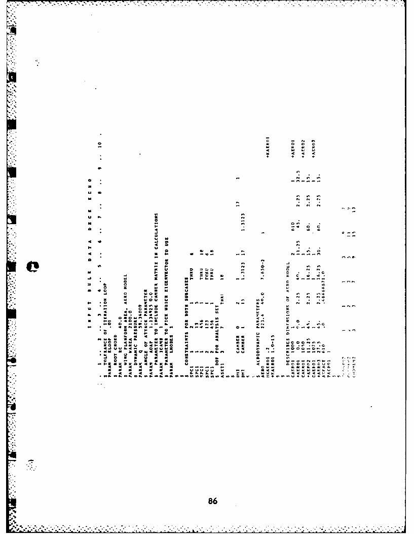
ow w
id 0 CIn 4 4
ba U
U0 o
we P. w 6. wTl ,0 I
so. .4 : !409
s 0 9 49 C, . 4
0c A2 -C -C I
.4 4c - C I . .2
4C U 6 & 46 & & N 0 cw C<<A -4496 ~ I9 "-6 46 1 0649 t f .i ) C.Q -+ +c-
7.1 -
.4. U* I.. N N8N

Oa 44 - 0ft@0a % M
-- M
16 -- 0--0-0 -.b.
MDOao * U-
P~m~.V~,U~~ 4 . z-- -- c0C0~.~00."'cz,0
r r. Nf0pp.., c--------
ol~h C, 0a CI 0000 M O00C 0 am mha ww u .. ..
-870000000~

+. 4.
IL~ -c
1-0LU~~ w w ~ -
hi 0
C,~~~ ~ ~ ~ -.C , ,VC c
0 6 . 6 46 1 IL1 6 A
88

- I--.-- -
e/
4N
89
. . . . . .. .~ .

~Or THIS PAGE (When Dat. EFntered)
REPORT DOCUMENTATION PAGE REA~DISTUCIONS
1REPORT NUMAIER 2. GOVT ACCESSION NO. S. RECIPIENTIS CATA1,OG NUM1BER1
AFIT/GAE/AA/82D-164. TITLE (and Subtitle) S. TYPE OF REPORT & PERIOD COVERED
STATIC AERIOELASTIC ANALYSIS OF US ThesisFEXIBLE WINGS VIA NASI'RAN S. PERFORMING ORG. REPORT MUNGER
7. AuTNOR(e) I. CONTRACT OR GRANT MU1111190e)
Kim JonesiLt.
9. PERFORMING ORGANIZATION NAME AND ADDRESS Ia. PROGRAM ELEMENT., PRJECT. TASK-AREA t& ORK UNIT V%1ER
Air Force Institute of Technology (AFIT-EN)* Wright-Patterson AMB, Ctaio 45433
It. CONTROLLING OFFICE NAME AND ADDRESS I*. REPORT DATE
Decaiiber 198218. MUNGER OF PAGES
13014. MONITORING AGENCY NAME SADOR9SS(Jf differenulf'e. Coelifte OffIo) It. SE9CURITY CLASS. (41 Od e.
Unclassifiedlad. OECDASIFICATION/DOWNGRADIMG
ISI. OISTRIISUTION STATEMENT (of tis Report)
Approved for public release; distribution unlimited
'7. DISTRIDUTION STATEMENT (.1 th* abstraot euatemd I Stck". N, at at. *m Roert)
IS. SUPPLEMENTARY NOTE11
fVrWOLA.. rar 1AW JPU 190.17.
AUr Force Iflswt. t Ioc ivL.. 1 , i
Is. KEY WORDS (Canthnue on reverse aide Iee MaassrOidedntify by Wleek nuiaber)
NASI'RAFlexible-wingsAeroelasticFluid-Structure Interfacing
20. ASISTRACT (CON1111 n fu ewere@ side it neoeavy and Ideadit, by bleak mmWbw)
The purpose of this study was to expand the capabilities of theStatic Flexible Wing Aeroelastic Sequence that Captain Lance P. Qirisingerdeveloped for NASIEAN as his Master's Thesis at AFIT. Captain Chrisingerdeveloped a basic procedure to enable NASIRAN to analyze flexible wingairloads and stresses. That capability is expanded to enable analysisof standard wing models.
D I AM 1473 EDITION OF I NOV so is 0SOLETE UNCU.SSIFIEDSECURITY CLASSIFICATION OF t1"16 PAGE (ohmUsa

FILM7D
3=8